

Thermal Energy Storage Using a Hybrid Composite Based on Technical-Grade Paraffin-AP25 Wax as a Phase Change Material


Abstract
:1. Introduction
2. Materials and Methods
2.1. Materials
2.2. Paraffin-AP25/Composite PCM Preparation
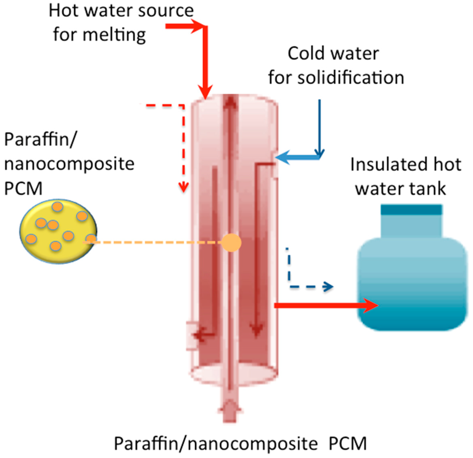
2.3. Experimental Methodology
2.4. Experimental Measurements and Characterization
3. Results and Discussion
3.1. Characterization of the Composite
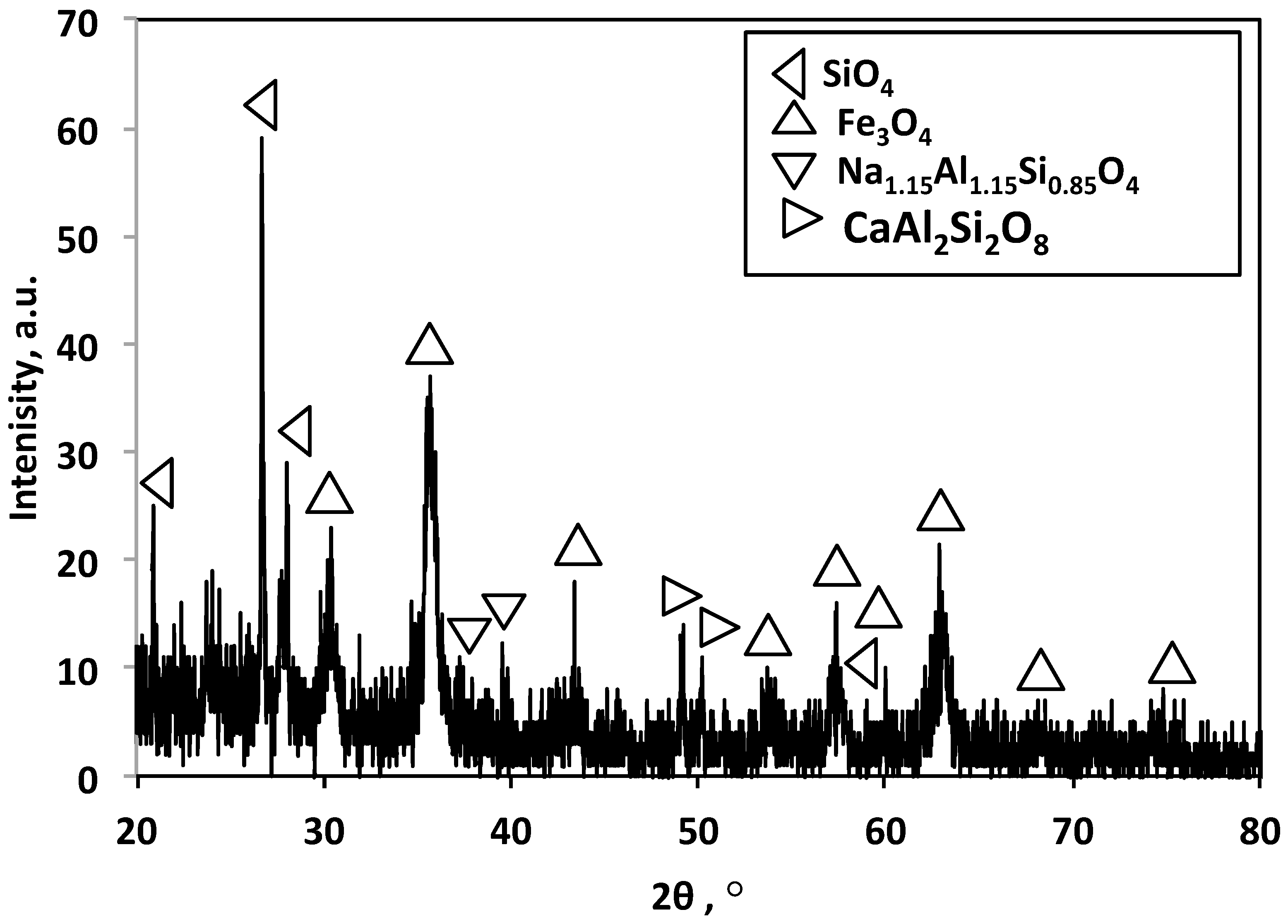
3.1.1. XRD
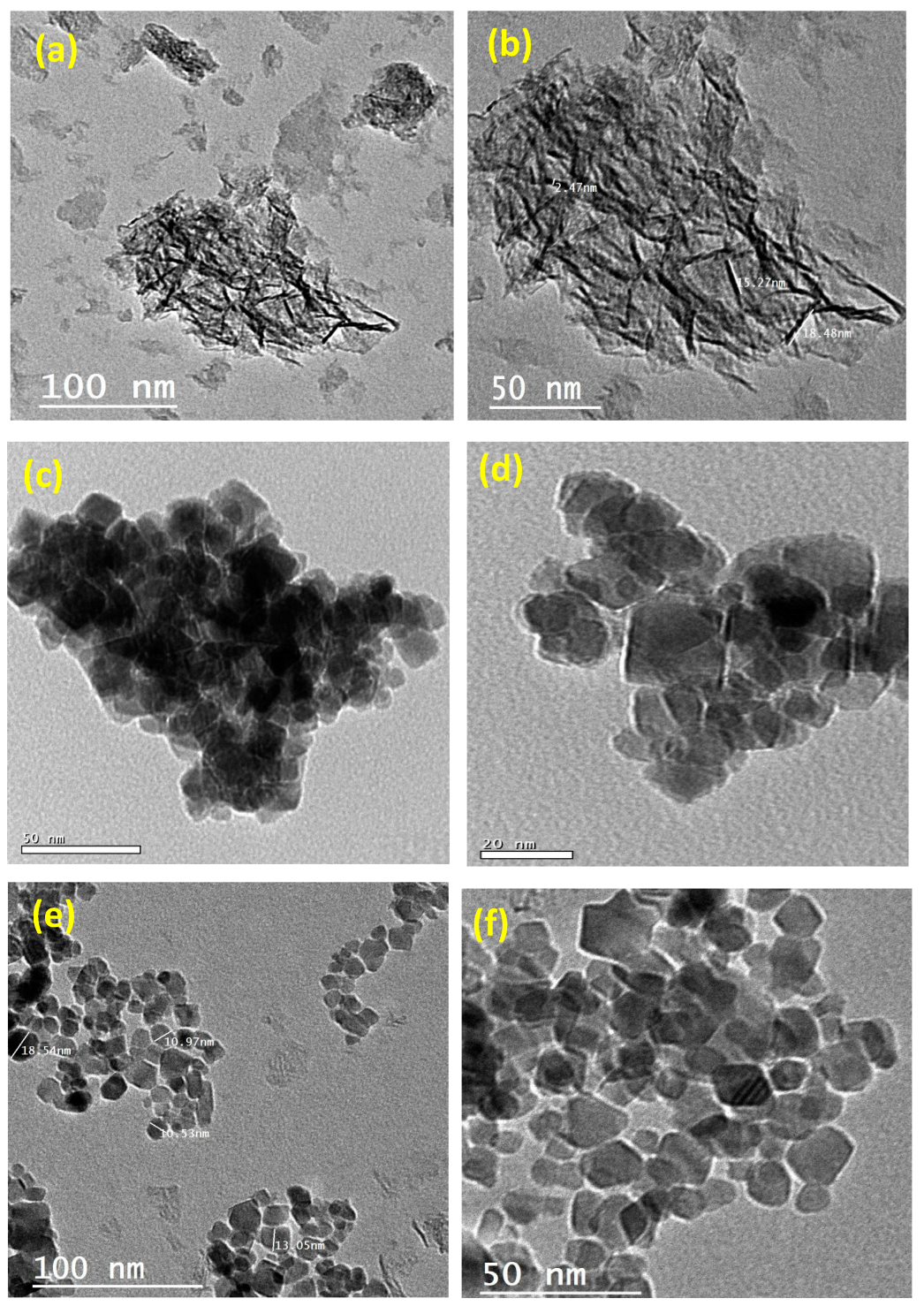
3.1.2. TEM Images
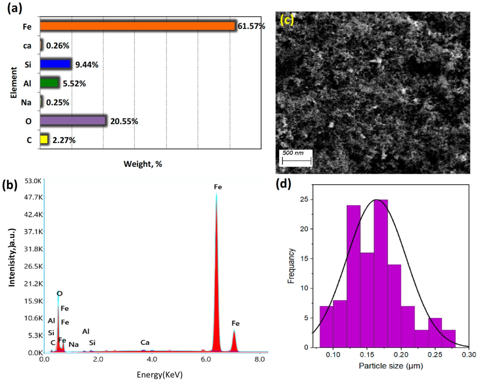
3.1.3. SEM Micrographs and EDX
3.2. Thermal Energy Storage Performance
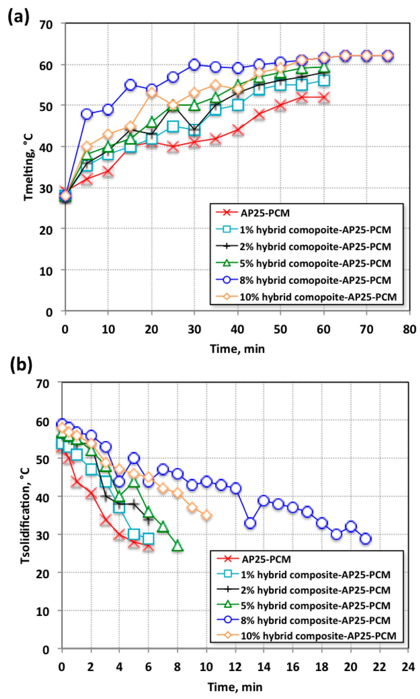
3.2.1. Studies on the PCM Charging/Discharging System
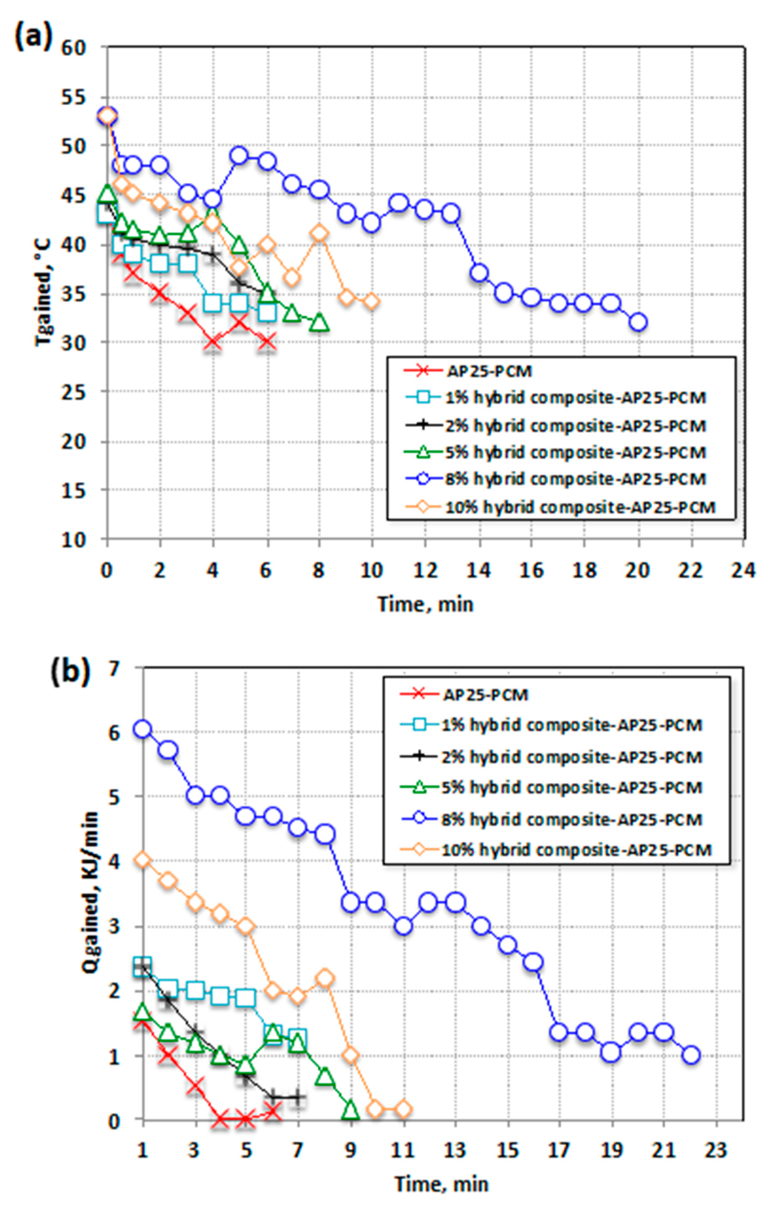
3.2.2. Heat Storage Density of Hybrid Composite–AP25 PCM
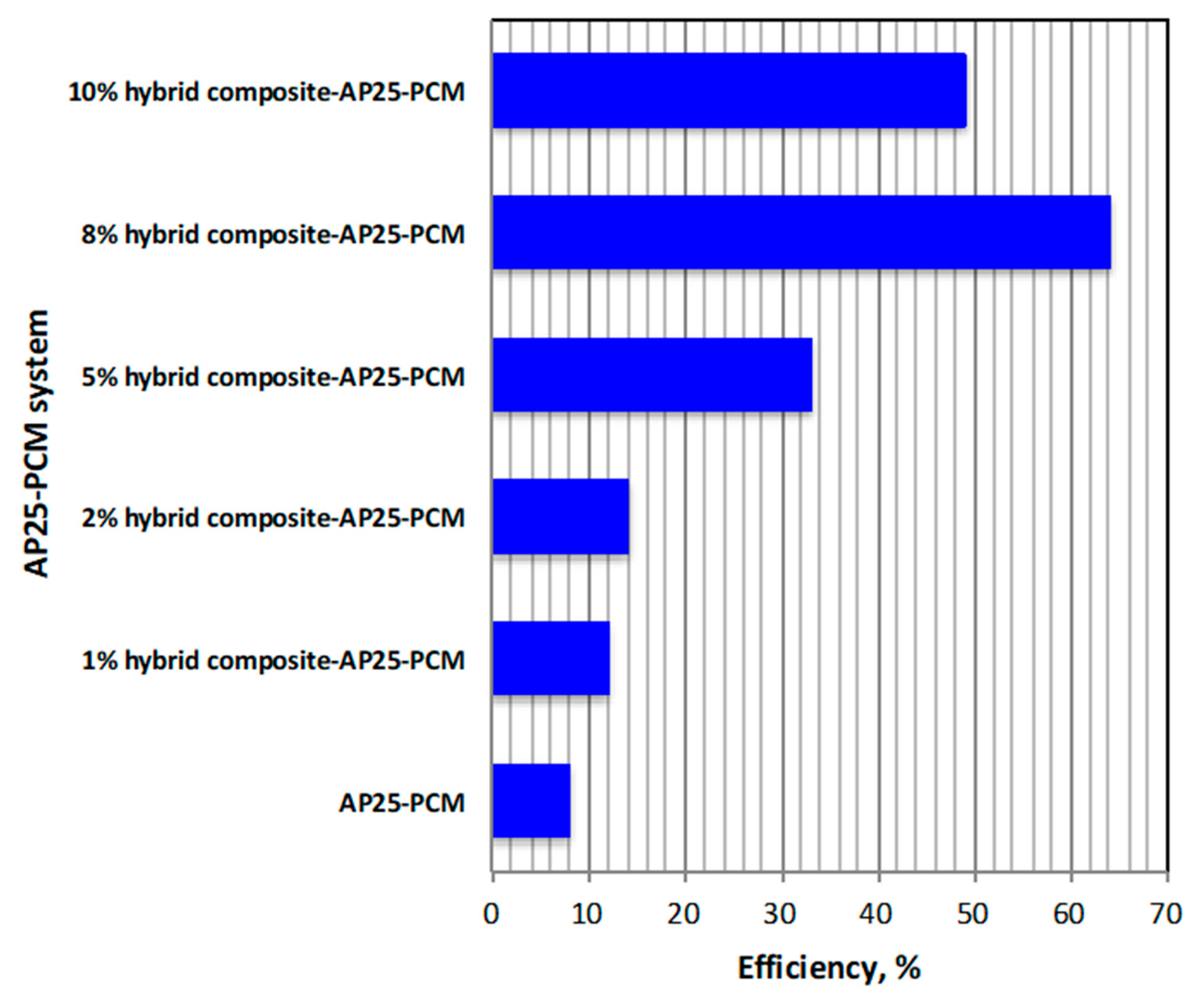
3.2.3. Overall System Performance Efficiency
3.2.4. Comparison of Various PCM Systems
4. Conclusions
Author Contributions
Funding
Data Availability Statement
Acknowledgments
Conflicts of Interest
References
- Du, K.; Calautit, J.; Wang, Z.; Wu, Y.; Liu, H. A review of the applications of phase change materials in cooling, heating and power generation in different temperature ranges. Appl. Energy 2018, 220, 242–273. [Google Scholar] [CrossRef]
- Raoux, S.; Wełnic, W.; Ielmini, D. Phase Change Materials and Their application to Nonvolatile Memories. Chem. Rev. 2010, 110, 240–267. [Google Scholar] [CrossRef] [PubMed]
- Singh, S.; Gaikwad, K.K.; Lee, Y.S. Phase change materials for advanced cooling packaging. Environ. Chem. Lett. 2018, 16, 845–859. [Google Scholar] [CrossRef]
- Li, X.; Zhou, Y.; Nian, H.; Zhang, X.; Dong, O.; Ren, X.; Zeng, J.; Hai, C.; Shen, Y. Advanced composite phase change material based on calcium chloride hexahydrate with aluminum oxide nanoparticles for thermal energy storage. Energy Fuels 2017, 31, 6560–6567. [Google Scholar] [CrossRef]
- Mustafa, B.; Al-Hadithi, M.B.; Alazawi, S.M. The effect of phase change material on thermal energy storage in cement layers. Int. J. Nanoelectron. Mater. 2016, 9, 133–142. [Google Scholar]
- Hassan, N.; Minakshi, M.; Liew, W.Y.H.; Amri, A.; Jiang, Z.-T. Thermal Characterization of Binary Calcium-Lithium Chloride Salts for Thermal Energy Storage at High Temperature. Energies 2023, 16, 4715. [Google Scholar] [CrossRef]
- Pawar, S.P.; Ghuge, N.C. Experimental Analysis of Phase Change Material during Charging Process. Int. Eng. Res. J. 2016, 530–536. [Google Scholar]
- Ali, H.; Abedin, M.; Rosen, A. A critical review of thermochemical energy storage systems. Open Renew. Energy J. 2011, 4, 42–46. [Google Scholar]
- Zondag, A.H. Chapter 6—Sorption Heat Storage. In Solar Energy Storage; Elsevier: Amsterdam, The Netherlands, 2015; pp. 135–154. [Google Scholar]
- Luo, L.; Le Pierres, N. Chapter 3—Innovative Systems for Storage of Thermal Solar Energy in Building. In Solar Energy Storage; Elsevier: Amsterdam, The Netherlands, 2015; pp. 27–62. [Google Scholar]
- Wong-Pinto, L.; Milian, Y.; Ushak, S. Progress on use of nanoparticles in salt hydrates as phase change materials. Renew. Sustain. Energy Rev. 2020, 122, 109727. [Google Scholar] [CrossRef]
- Blanco, M.J.; Santigosa, L.R. Advances in Concentrating Solar Thermal Research and Technology; Woodhead Publishing Series in Energy: Cambridge, UK, 2017; pp. 213–246. [Google Scholar] [CrossRef]
- Teng, T.-P.; Yu, C. Characteristics of phase-change materials containing oxide nano-additives for thermal storage. Nanoscale Res. Lett. 2012, 7, 611. [Google Scholar] [CrossRef]
- Sarbu, I.; Dorc, A. A review of modelling and optimisation techniques for district heating systems. Int. J. Energy Res. 2019, 43, 29. [Google Scholar] [CrossRef]
- Sharma, A.; Tyagi, V.; Chen, C.; Buddhi, D. Review on thermal energy storage with phase change materials and applications. Renew. Sustain. Energy Rev. 2009, 13, 318–345. [Google Scholar] [CrossRef]
- Kant, K.; Shukla, A.; Sharma, A.; Biwole, P. Heat transfer study of phase change materials with graphene nano particle for thermal energy storage. Sol. Energy 2017, 146, 453–463. [Google Scholar] [CrossRef]
- Bianco, N.; Caliano, M.; Fragnito, A.; Iasiello, M.; Mauro, G.M.; Mongibello, L. Thermal analysis of micro-encapsulated phase change material (MEPCM)-based units integrated into a commercial water tank for cold thermal energy storage. Energy 2023, 266, 126479. [Google Scholar] [CrossRef]
- NematpourKeshteli, A.; Iasiello, M.; Langella, G.; Bianco, N. Increasing melting and solidification performances of a phase change material-based flat plate solar collector equipped with metal foams, nanoparticles, and wavy wall-Y-shaped surface. Energy Convers. Manag. 2023, 291, 117268. [Google Scholar] [CrossRef]
- Sharma, H.K.; Kumar, S.; Kumar, S.; Verma, S.K. Performance investigation of flat plate solar collector with nanoparticle enhanced integrated thermal energy storage system. J. Energy Storage 2022, 55, 105681. [Google Scholar] [CrossRef]
- Shchukina, E.M.; Graham, M.; Zheng, Z.; Shchukin, D.G. Nanoencapsulation of phase change materials for advanced thermal energy storage systems. Chem. Soc. Rev. 2018, 47, 4156. [Google Scholar] [CrossRef]
- Yang, G.; Yim, Y.-J.; Lee, J.W.; Heo, Y.-J.; Park, S.-J. Carbon-Filled Organic Phase-Change Materials for Thermal Energy Storage: A Review. Molecules 2019, 24, 2055. [Google Scholar] [CrossRef]
- Thabet, R.H.; Fouad, M.K.; Sherbiny SA, E.; Tony, M.A. Zero-Waste Approach: Assessment of Aluminum-Based Waste as a Photocatalyst for Industrial Wastewater Treatment Ecology. Int. J. Environ. Res. 2022, 16, 36. [Google Scholar] [CrossRef]
- Muthukannan, V.; Praveen, K.; Natesan, B. Fabrication and characterization of magnetite/reduced graphene oxide composite incurred from iron ore tailings for high performance application. Mater. Chem. Phys. 2015, 162, 400–407. [Google Scholar] [CrossRef]
- Hilder, M.; Winther-Jensen, O.; Winther-Jensen, B.; MacFarlane, D.R. Graphene/zinc nano-composites by electrochemical co-deposition. Phys. Chem. Chem. Phys. 2012, 14, 14034–14040. [Google Scholar] [CrossRef]
- Kurtbas, I.; Durmuş, A. Efficiency and exergy analysis of a new solar air heater. Renew. Energy 2004, 29, 1489–1501. [Google Scholar] [CrossRef]
- Ramasamy, M.; Das, M.; An, S.S.A.; Yi, D.K. Role of surface modification in zinc oxide nanoparticles and its toxicity assessment toward human dermal fibroblast cells. Int. J. Nanomed. 2014, 9, 3707. [Google Scholar]
- Lv, Q.; Li, G.; Lu, H.; Cai, W.; Huang, H.; Cheng, C. Preparation of magnetic zeolite γ-Fe2O3/TS-1 with core/shell structure and application in photocatalytic degradation. Microporous Mesoporous Mater. 2015, 203, 202–207. [Google Scholar] [CrossRef]
- Pise, A.T.; Waghmare, A.V.; Talandage, V.G. Heat transfer enhancement by using nanomaterial in phase change material for latent heat thermal energy storage system. Asian J. Eng. Appl. Technol. 2013, 2, 52–57. [Google Scholar] [CrossRef]
- Khan, Z.; Khan, Z.A. Experimental and numerical investigations of nano-additives enhanced paraffin in a shell-and-tube heat exchanger: A comparative study. Appl. Therm. Eng. 2018, 143, 777–790. [Google Scholar] [CrossRef]
- Chieruzzi, M.; Miliozzi, A.; Crescenzi, T.; Torre, L.; Kenny, J.M. A new phase change material based on potassium nitrate with silica and alumina nanoparticles for thermal energy storage. Nanoscale Res. Lett. 2015, 10, 273. [Google Scholar] [CrossRef] [PubMed]
- Kaygusuz, K.; Sari, A. Thermal energy storage system using a technical grade paraffin wax as latent heat energy storage material. Energy Sources 2005, 27, 1535–1546. [Google Scholar] [CrossRef]
- Tony, M.A. Nexus approach: ZSM12 derived from industrial waste and organic wax pair for microencapsulated solar energy storage system. Energy Sources Part A Recovery Util. Environ. Eff. 2021. [Google Scholar] [CrossRef]
- Sun, N.; Xiao, Z. Synthesis and performances of phase change materials microcapsules with a polymer/BN/TiO2 hybrid shell for thermal energy storage. Energy Fuels 2017, 31, 10186–10195. [Google Scholar] [CrossRef]
- Tony, M.A. From biomass residue to solar thermal energy: The potential of bagasse as a heat storage material. Euro-Mediterr. J. Environ. Integr. 2020, 5, 1–9. [Google Scholar] [CrossRef]
- Ramakrishnan, S.; Wang, X.; Sanjayan, J.; Wilson, J. Heat transfer performance enhancement of paraffin/expanded perlite phase change composites with graphene nano-platelets. Energy Procedia 2017, 105, 4866–4871. [Google Scholar] [CrossRef]
- Tony, M.A. Recent frontiers in solar energy storage via nanoparticles enhanced phase change materials: Succinct review on basics, applications and their environmental aspects. Energy Storage 2021, 3, e238. [Google Scholar] [CrossRef]
- Al-Kayiem, H.H.; Lin, S.C. Performance evaluation of a solar water heater integrated with a PCM nanocomposite TES at various inclinations. Solar Energy 2014, 109, 82–92. [Google Scholar] [CrossRef]
- Valentini, F.; Dorigato, A.; Pegoretti, A.; Tomasi, M.; Sorarù, G.D.; Biesuz, M. Si3N4 nanofelts/paraffin composites as novel thermal energy storage architecture. J. Mater. Sci. 2021, 56, 1537–1550. [Google Scholar] [CrossRef]
- Tony, M.A.; Mansour, S.A. Mansour, Sunlight-driven organic phase change material-embedded nanofiller for latent heat solar energy storage. Int. J. Environ. Sci. Technol. 2019, 17, 709–720. [Google Scholar] [CrossRef]
- Bahiraei, F.; Fartaj, A.; Nazri, G.-A. Experimental and numerical investigation on the performance of carbon-based nanoenhanced phase change materials for thermal management applications. Energy Convers. Manag. 2017, 153, 115–128. [Google Scholar] [CrossRef]
- Zabalegui, A.; Lokapur, D.; Lee, H. Nanofluid PCMs for thermal energy storage: Latent heat reduction mechanisms and a numerical study of effective thermal storage performance. Int. J. Heat Mass Transf. 2014, 78, 1145–1154. [Google Scholar] [CrossRef]
- Qureshi, Z.A.; Ali, H.M.; Khushnood, S. Recent advances on thermal conductivity enhancement of phase change materials for energy storage system: A review. Int. J. Heat Mass Transf. 2018, 127, 838–856. [Google Scholar] [CrossRef]


| Property | Value | Unit |
|---|---|---|
| Melting temperature | 48–53 | °C |
| Latent heat of fusion | 190 | kJ/kg |
| Solid density | 930 | kg/m3 |
| Liquid density | 830 | kg/m3 |
| Thermal conductivity | 0.21 | kJ/kg°C |
| Solid specific | 2.1 | kJ/kg°C |
| Density (solid/liquid) | 833/775 | kg/m3 |
| Kinematic viscosity | 8.3 × 10⁻⁵ | m2/s |
| Composite PCM Type | Efficiency Enhancement | Ref. |
|---|---|---|
| Hybrid Fe/Al/Si | 64% | Current study |
| Zeolite | 85% | [34] |
| Graphene nanoplates | 49% | [35] |
| SiO2 | 6% | [36] |
| Cu | 52% | [37] |
| Si3N4 | 77.4% | [38] |
| ZnO/SiO2 | 19% | [39] |
| Graphene nanoplatelets | 100% | [40] |
| Carbon nanotubes | 86% | [41] |
| Aluminum nitride | 36.47% | [28] |
| TiO2 | 0.46% | [13] |
Disclaimer/Publisher’s Note: The statements, opinions and data contained in all publications are solely those of the individual author(s) and contributor(s) and not of MDPI and/or the editor(s). MDPI and/or the editor(s) disclaim responsibility for any injury to people or property resulting from any ideas, methods, instructions or products referred to in the content. |
© 2023 by the authors. Licensee MDPI, Basel, Switzerland. This article is an open access article distributed under the terms and conditions of the Creative Commons Attribution (CC BY) license (https://creativecommons.org/licenses/by/4.0/).
Share and Cite
Nabwey, H.A.; Tony, M.A. Thermal Energy Storage Using a Hybrid Composite Based on Technical-Grade Paraffin-AP25 Wax as a Phase Change Material. Nanomaterials 2023, 13, 2635. https://doi.org/10.3390/nano13192635
Nabwey HA, Tony MA. Thermal Energy Storage Using a Hybrid Composite Based on Technical-Grade Paraffin-AP25 Wax as a Phase Change Material. Nanomaterials. 2023; 13(19):2635. https://doi.org/10.3390/nano13192635
Chicago/Turabian StyleNabwey, Hossam A., and Maha A. Tony. 2023. "Thermal Energy Storage Using a Hybrid Composite Based on Technical-Grade Paraffin-AP25 Wax as a Phase Change Material" Nanomaterials 13, no. 19: 2635. https://doi.org/10.3390/nano13192635
APA StyleNabwey, H. A., & Tony, M. A. (2023). Thermal Energy Storage Using a Hybrid Composite Based on Technical-Grade Paraffin-AP25 Wax as a Phase Change Material. Nanomaterials, 13(19), 2635. https://doi.org/10.3390/nano13192635