
Polyethylene Oxide Assisted Fish Collagen-Poly-ε-Caprolactone Nanofiber Membranes by Electrospinning


Abstract
:1. Introduction
2. Materials and Methods
2.1. Materials and Equipment
2.2. Preparation of FC-PCL Nanofiber Membranes
2.2.1. PEO Spinning
2.2.2. FC/PCL Ratio
2.2.3. Removal of Sacrificial Fibers of PEO
2.3. Physical and Chemical Properties Testing
2.3.1. SEM
2.3.2. Swelling Rate
2.3.3. Hydrolysis Stability
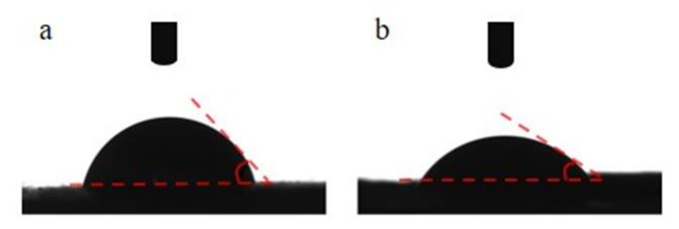
2.3.4. Contact Angle
2.3.5. FTIR
2.3.6. Tensile Breaking Strength Test
2.3.7. Porosity
2.4. Cell Culture
2.4.1. Cell Adhesion
2.4.2. Dead/Live Cell Text
2.5. Safety and Degradation Tests In Vivo
2.6. Statistical Analysis
3. Results and Discussion
3.1. Preparation of FC-PCL Nanofiber Membrane
3.1.1. PEO Spinning
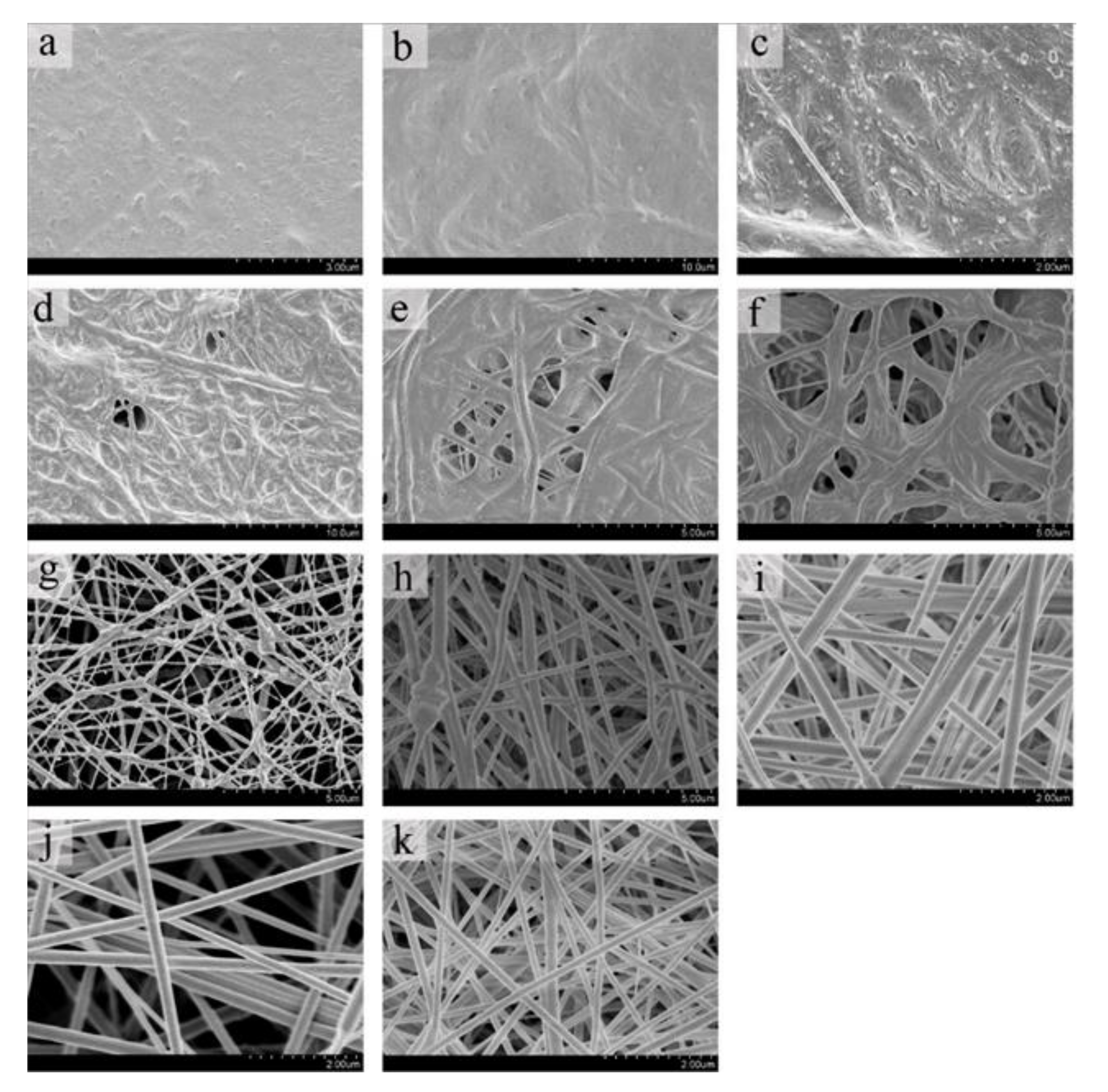
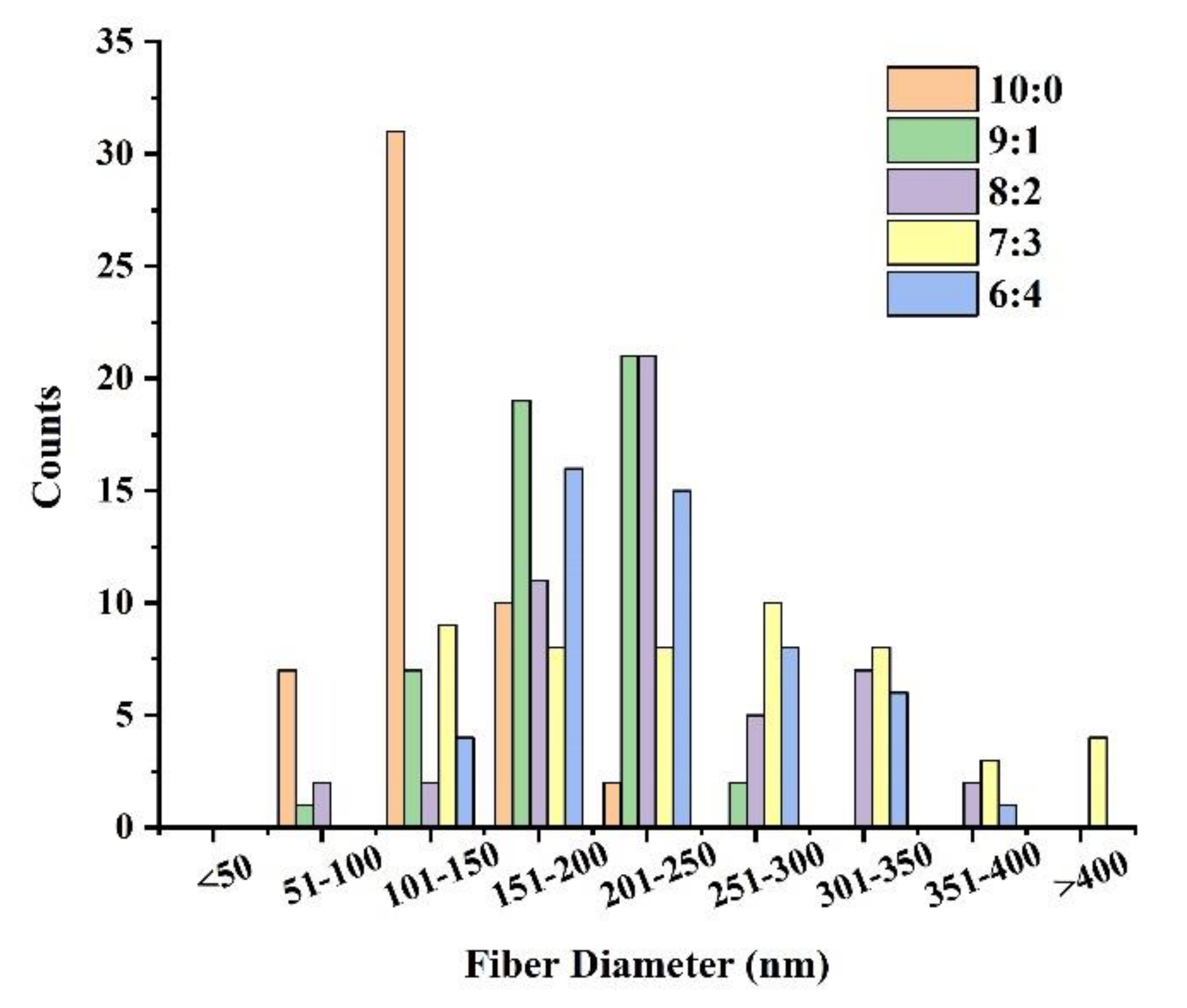
3.1.2. FC/PCL Ratio
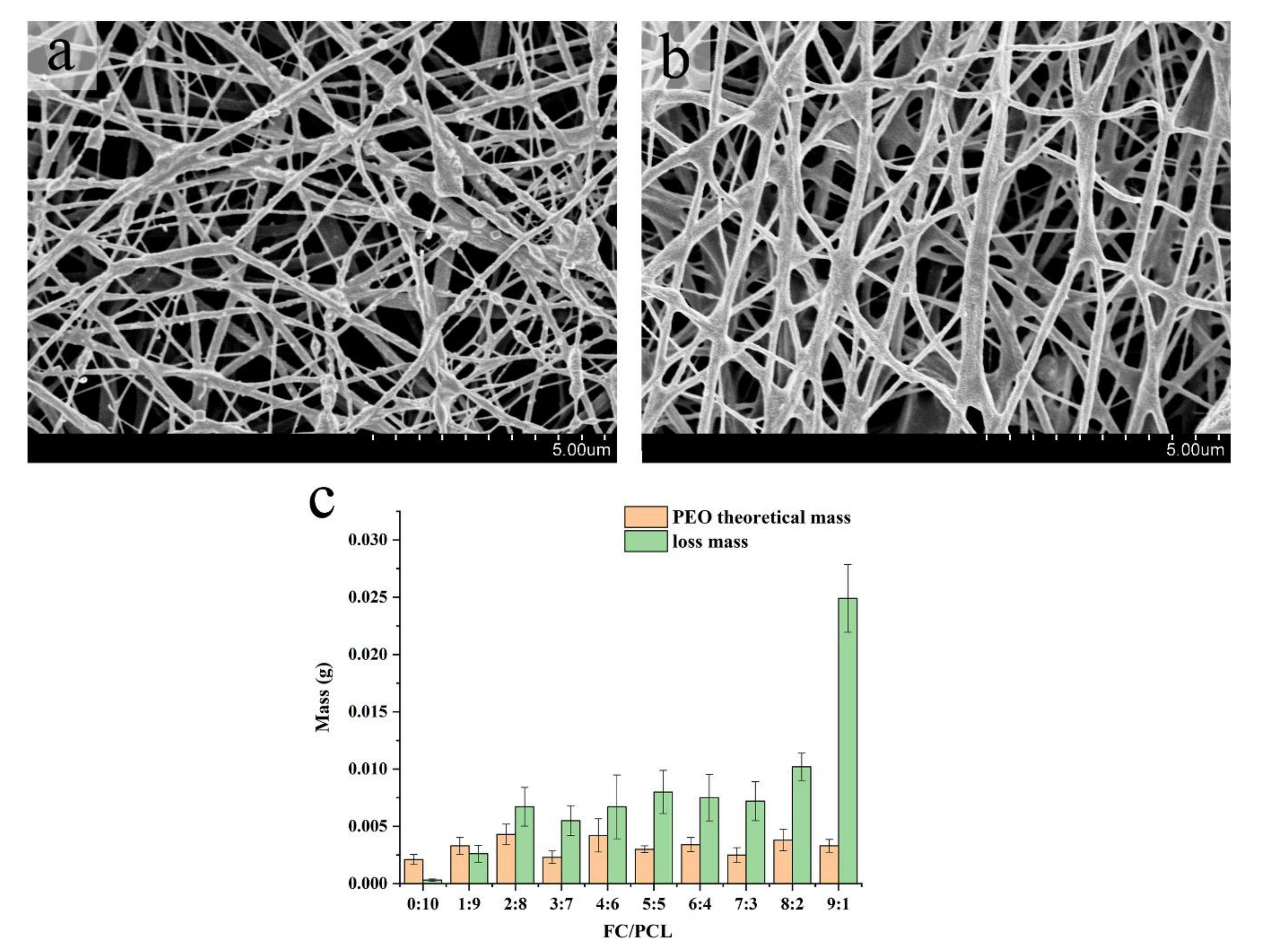
3.1.3. Removal of Sacrificial Fibers of PEO
3.2. Physical and Chemical Properties Testing
3.2.1. FTIR
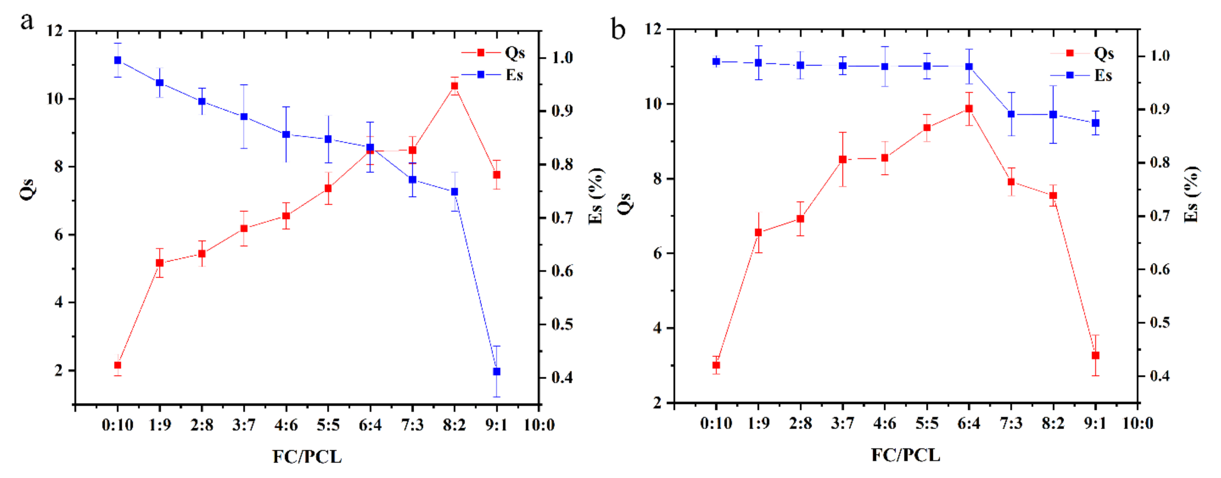
3.2.2. Swelling Rate and Hydrolysis Stability
3.3. Cell Culture
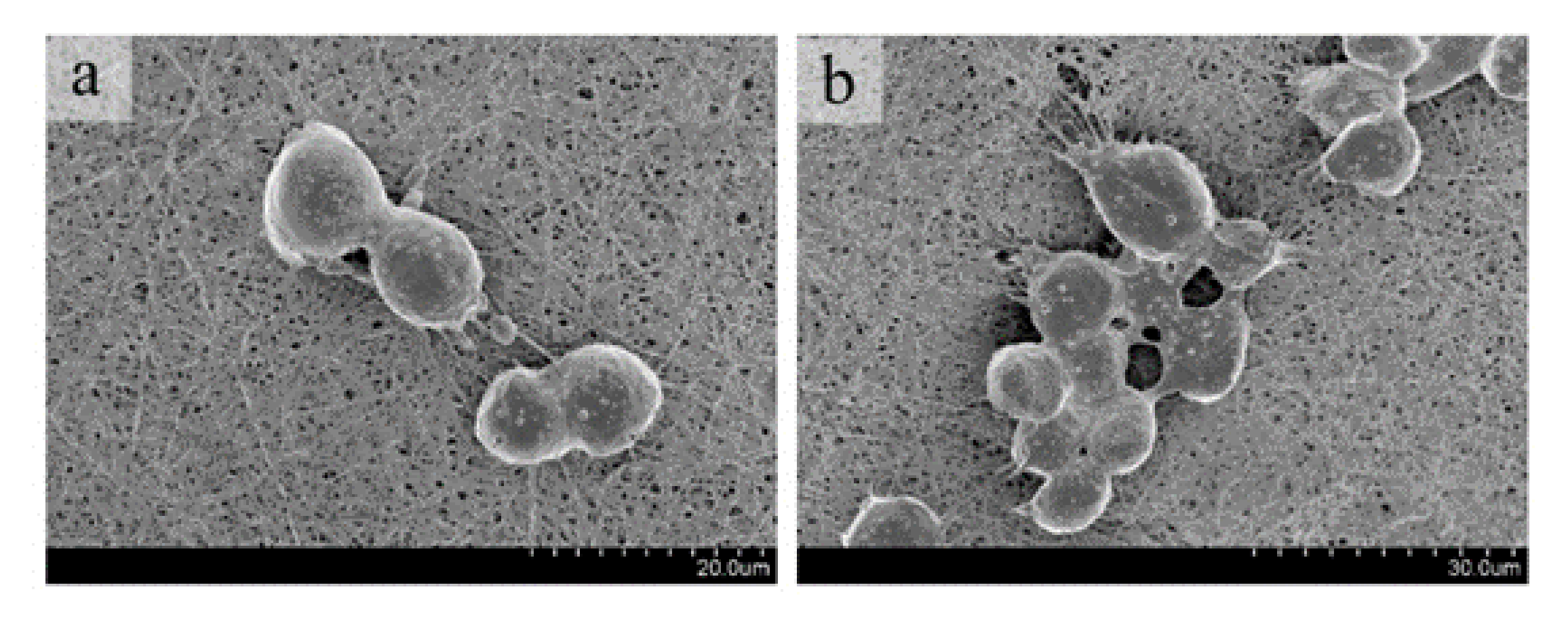
3.3.1. Cell Adhesion
3.3.2. Dead/Live Cell Text
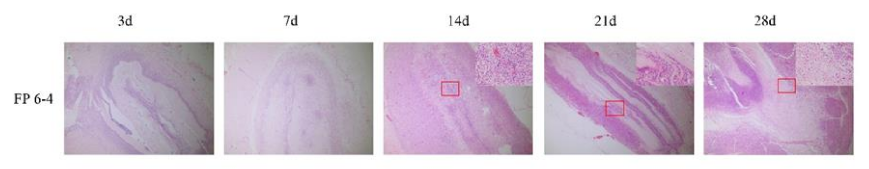
3.4. Safety and Degradation Tests In Vivo
4. Conclusions
Author Contributions
Funding
Institutional Review Board Statement
Informed Consent Statement
Data Availability Statement
Acknowledgments
Conflicts of Interest
References
- Dippold, D.; Cai, A.; Hardt, M.; Boccaccini, A.R.; Horch, R.E.; Beier, J.P.; Schubert, D.W. Investigation of the batch-to-batch inconsistencies of Collagen in PCL-Collagen nanofibers. Mater. Sci. Eng. C 2019, 95, 217–225. [Google Scholar] [CrossRef] [PubMed]
- Bi, C.; Li, X.; Xin, Q.; Han, W.; Shi, C.; Guo, R.; Shi, W.; Qiao, R.; Wang, X.; Zhong, J. Effect of extraction methods on the preparation of electrospun/electrosprayed microstructures of tilapia skin collagen. J. Biosci. Bioeng. 2019, 128, 234–240. [Google Scholar] [CrossRef] [PubMed]
- Ibrahim, A.; Hassan, D.; Kelany, N.; Kotb, S.; Soliman, M. Validation of Three Different Sterilization Methods of Tilapia Skin Dressing: Impact on Microbiological Enumeration and Collagen Content. Front. Veter. Sci. 2020, 7, 9. [Google Scholar] [CrossRef] [PubMed]
- Tang, L.; Chen, S.; Su, W.; Weng, W.; Osako, K.; Tanaka, M. Physicochemical properties and film-forming ability of fish skin collagen extracted from different freshwater species. Process Biochem. 2015, 50, 148–155. [Google Scholar] [CrossRef]
- Le Corre-Bordes, D.; Hofman, K.; Hall, B. Guide to electrospinning denatured whole chain collagen from hoki fish using benign solvents. Int. J. Biol. Macromol. 2018, 112, 1289–1299. [Google Scholar] [CrossRef]
- Subhan, F.; Hussain, Z.; Tauseef, I.; Shehzad, A.; Wahid, F. A review on recent advances and applications of fish collagen. Crit. Rev. Food Sci. Nutr. 2020, 61, 1027–1037. [Google Scholar] [CrossRef]
- García-Hernández, A.B.; Morales-Sánchez, E.; Calderón-Domínguez, G.; Salgado-Cruz, M.D.L.P.; Farrera-Rebollo, R.R.; Vega-Cuellar, M.Á.; García-Bórquez, A. Hydrolyzed collagen on PVA-based electrospun membranes: Synthesis and characterization. J. Appl. Polym. Sci. 2021, 138, 51197. [Google Scholar] [CrossRef]
- Hernández-Rangel, A.; Martin-Martinez, E.S. Collagen based electrospun materials for skin wounds treatment. J. Biomed. Mater. Res. Part A 2021, 14, 1751–1764. [Google Scholar] [CrossRef]
- Aghmiuni, A.I.; Keshel, S.H.; Sefat, F.; AkbarzadehKhiyavi, A. Fabrication of 3D hybrid scaffold by combination technique of electrospinning-like and freeze-drying to create mechanotransduction signals and mimic extracellular matrix function of skin. Mater. Sci. Eng. C 2020, 120, 111752. [Google Scholar] [CrossRef]
- Bokova, E.S.; Kovalenko, G.M.; Filatov, I.Y.; Pawlowa, M.; Stezhka, K.S. Obtaining New Biopolymer Materials by Electrospinning. Fibres Text. East. Eur. 2017, 25, 31–33. [Google Scholar] [CrossRef]
- Chakrapani, V.Y.; Gnanamani, A.; Giridev, V.; Madhusoothanan, M.; Sekaran, G. Electrospinning of type I collagen and PCL nanofibers using acetic acid. J. Appl. Polym. Sci. 2012, 125, 3221–3227. [Google Scholar] [CrossRef]
- Chen, Z.; Mo, X.; He, C.; Wang, H. Intermolecular interactions in electrospun collagen–chitosan complex nanofibers. Carbohydr. Polym. 2008, 72, 410–418. [Google Scholar] [CrossRef]
- Liu, X.; Zheng, S.; Dan, W.; Dan, N. Ultrasound-mediated preparation and evaluation of a collagen/PVP-PCL micro- and nanofiber scaffold electrospun from chloroform/ethanol mixture. Fibers Polym. 2016, 17, 1186–1197. [Google Scholar] [CrossRef]
- Selvaraj, S.; Ramalingam, S.; Parida, S.; Rao, J.R.; Nishter, N.F. Chromium containing leather trimmings valorization: Sustainable sound absorber from collagen hydrolysate intercalated electrospun nanofibers. J. Hazard. Mater. 2021, 405, 124231. [Google Scholar] [CrossRef]
- Szentivanyi, A.; Assmann, U.; Schuster, R.; Glasmacher, B. Production of biohybrid protein/PEO scaffolds by electrospinning. Mater. Werkst. 2009, 40, 65–72. [Google Scholar] [CrossRef]
- Tu, H.; Bao, M.; Li, Q.; Li, B.; Yuan, H.; Zhang, Y. Aligned core–shell structured ultrafine composite fibers of PLLA–collagen for tendon scaffolding. J. Control. Release 2013, 172, e128. [Google Scholar] [CrossRef]
- Zhou, J.; Cao, C.; Ma, X.; Lin, J. Electrospinning of silk fibroin and collagen for vascular tissue engineering. Int. J. Biol. Macromol. 2010, 47, 514–519. [Google Scholar] [CrossRef]
- Afewerki, S.; Bassous, N.; Harb, S.V.; Corat, M.A.F.; Maharjan, S.; Ruiz-Esparza, G.U.; de Paula, M.M.M.; Webster, T.J.; Tim, C.R.; Viana, B.C.; et al. Engineering multifunctional bactericidal nanofibers for abdominal hernia repair. Commun. Biol. 2021, 4, 1–14. [Google Scholar] [CrossRef] [PubMed]
- Park, S.; Kim, J.; Lee, M.-K.; Park, C.; Jung, H.-D.; Kim, H.-E.; Jang, T.-S. Fabrication of strong, bioactive vascular grafts with PCL/collagen and PCL/silica bilayers for small-diameter vascular applications. Mater. Des. 2019, 181, 10. [Google Scholar] [CrossRef]
- Metwally, S.; Ferraris, S.; Spriano, S.; Krysiak, Z.J.; Kaniuk, Ł.; Marzec, M.M.; Kim, S.K.; Szewczyk, P.K.; Gruszczyński, A.; Wytrwal-Sarna, M.; et al. Surface potential and roughness controlled cell adhesion and collagen formation in electrospun PCL fibers for bone regeneration. Mater. Des. 2020, 194, 108915. [Google Scholar] [CrossRef]
- Ching, K.Y.; Andriotis, O.; Sengers, B.; Stolz, M. Genipin crosslinked chitosan/PEO nanofibrous scaffolds exhibiting an improved microenvironment for the regeneration of articular cartilage. J. Biomater. Appl. 2021, 36, 503–516. [Google Scholar] [CrossRef] [PubMed]
- Tenchurin, T.K.; Belousov, S.I.; Kiryukhin, Y.I.; Istranov, L.P.; Istranova, E.V.; Shepelev, A.D.; Mamagulashvili, V.G.; Kamyshinsky, R.; Chvalun, S.N. Control on rheological behavior of collagen 1 dispersions for efficient electrospinning. J. Biomed. Mater. Res. Part A 2019, 107, 312–318. [Google Scholar] [CrossRef] [PubMed]
- Gao, J.; Guo, H.; Zhao, L.; Zhao, X.; Wang, L. Water-stability and biological behavior of electrospun collagen/PEO fibers by environmental friendly crosslinking. Fibers Polym. 2017, 18, 1496–1503. [Google Scholar] [CrossRef]
- Shin, J.W.; Lee, Y.J.; Heo, S.J.; Park, S.A.; Kim, S.-H.; Kim, Y.J.; Kim, D.-H.; Shin, J.-W. Manufacturing of Multi-Layered Nanofibrous Structures Composed of Polyurethane and Poly(ethylene oxide) as Potential Blood Vessel Scaffolds. J. Biomater. Sci. Polym. Ed. 2009, 20, 757–771. [Google Scholar] [CrossRef]
- Hodge, J.; Quint, C. The improvement of cell infiltration in an electrospun scaffold with multiple synthetic biodegradable polymers using sacrificial PEO microparticles. J. Biomed. Mater. Res. Part A 2019, 107, 1954–1964. [Google Scholar] [CrossRef]


| PEO Content (%) | Spinning Result |
|---|---|
| 0.2 | Unstable |
| 0.4 | Unstable |
| 0.6 | Film |
| 0.8 | Film |
| 1.0 | Unstable |
| 1.2 | Unstable, the needle was easy to block |
| Polymer | Wavenumber (cm−1) | Assignment |
|---|---|---|
| FC | 3398 | amide A band, N-H stretching vibration |
| 1662 | amide I band, C=O tensile vibration | |
| 1550 | amide II band, N-H and C-H bending | |
| 1238 | amide III band, C-O stretching vibration | |
| PCL | 2962 and 2859 | CH2 stretching (asymmetric and symmetric) |
| 1728 | C=O stretching | |
| 1290 | C-C stretching | |
| 1241 | C-O-C asymmetric stretching | |
| PEO | 2887 | CH2 stretching |
| 1454 | C-H bending | |
| 1352, 1280 and 820 | C-H deformation of the methyl group | |
| 1174, 1053 and 957 | C-O-C stretching vibration |
| Before PEO Removal | After PEO Removal | |
|---|---|---|
| Contact angle (°) | 74.39 ± 2.84 | 24.48 ± 7.94 |
| Elongation (%) | 10.67 ± 3.51 | 13.67 ± 1.15 |
| Tensile strength (MPa) | 145.57 ± 44.08 | 112.45 ± 22.34 |
| Elastic Modulus (MPa) | 4635.33 ± 579.50 | 2751.00 ± 426.18 |
| Porosity (%) | 61.56 ± 3.916 | 87.6 ± 9.273 |
Publisher’s Note: MDPI stays neutral with regard to jurisdictional claims in published maps and institutional affiliations. |
© 2022 by the authors. Licensee MDPI, Basel, Switzerland. This article is an open access article distributed under the terms and conditions of the Creative Commons Attribution (CC BY) license (https://creativecommons.org/licenses/by/4.0/).
Share and Cite
He, X.; Wang, L.; Lv, K.; Li, W.; Qin, S.; Tang, Z. Polyethylene Oxide Assisted Fish Collagen-Poly-ε-Caprolactone Nanofiber Membranes by Electrospinning. Nanomaterials 2022, 12, 900. https://doi.org/10.3390/nano12060900
He X, Wang L, Lv K, Li W, Qin S, Tang Z. Polyethylene Oxide Assisted Fish Collagen-Poly-ε-Caprolactone Nanofiber Membranes by Electrospinning. Nanomaterials. 2022; 12(6):900. https://doi.org/10.3390/nano12060900
Chicago/Turabian StyleHe, Xiaoli, Lei Wang, Kangning Lv, Wenjun Li, Song Qin, and Zhihong Tang. 2022. "Polyethylene Oxide Assisted Fish Collagen-Poly-ε-Caprolactone Nanofiber Membranes by Electrospinning" Nanomaterials 12, no. 6: 900. https://doi.org/10.3390/nano12060900
APA StyleHe, X., Wang, L., Lv, K., Li, W., Qin, S., & Tang, Z. (2022). Polyethylene Oxide Assisted Fish Collagen-Poly-ε-Caprolactone Nanofiber Membranes by Electrospinning. Nanomaterials, 12(6), 900. https://doi.org/10.3390/nano12060900