2. Materials and Methods
Ferrocene (FeCp
2, Fe(C
5H
5)
2, 98%, Sigma-Aldrich, St. Louis, MO, USA), acetylferrocene (C
12H
12FeO, 95%, Sigma-Aldrich, St. Louis, MO, USA), ferrocenemethanol (C
11H
12FeO, 97%, Sigma-Aldrich, St. Louis, MO, USA), and 1,1′-diacetylferrocene (C
14H
14FeO
2, 97%, Sigma-Aldrich, St. Louis, MO, USA) were used without purification as catalysts, just as they were received. Aerogel-like carbon nanotubes were synthesized via the floating catalyst chemical vapor deposition (FC-CVD) method (
Figure S1). The stock solution comprised acetone, organometallic compounds, and thiophene (C
4H
4S, ≥99%, Sigma-Aldrich, St. Louis, MO, USA); this solution was injected into a reactor at a rate of 12 mL/h and a heating zone temperature of 1200 °C. The ferrocene derived organometallic compound-to-thiophene molar ratio was set to 1 (mol/mol). Hydrogen was used as the carrier gas. The aerogel-like carbon nanotubes were synthesized in the outstream area and collected in the final chamber.
The synthesized CNTs were characterized through Raman spectroscopy (Renishaw, in a via excited by a 514-nm laser), transmission electron microscopy (TEM, Technai G2 F20, FEI, Hillsboro, OR, USA), field-emission scanning electron microscopy (FE-SEM, Verios 460, FEI, Hillsboro, OR, USA), X-ray photoelectron spectroscopy (XPS, K-Alpa, Thermo Fisher Scientific, Walthan, MA, USA), and X-ray diffraction (XRD, by Cu Kα radiation, 45 kV, 200 mA, Smartlab, Rigaku, Tokyo, Japan). The thermodynamic reaction of catalyst precursors was analyzed through thermogravimetric-differential scanning calorimetry (TG-DSC, Labsys Evo, Setaram, Caluire, France). The heating rate was 10 °C/min with a low of Ar. The decomposed gas analyzed by process gas monitor with mass spectroscopy (BGM202, Ulvac, Chigasaki, Japan)
Density functional theory (DFT) simulation were carried out using the plain-wave QUANTUM ESPRESSO package [
18]. Generalized gradient approximation (GGA) was used with the Perdew–Burke–Ernzerhof (PBE) functional of ultra-soft pseudopotentials. The kinetic energy cutoff was set as 80 Ry with convergence criteria of 10
−2 eVÅ
−1. Total energy of isolated molecule was calculated at the gamma point in a cubic cell with a 30 Å edge length. All molecules of ferrocene and ferrocene derivatives were fully relaxed before self-consistent field (SCF) calculation. The bond dissociation energy was obtained by comparing the difference in energy before and after removing atoms/fragments from the molecule.
3. Results
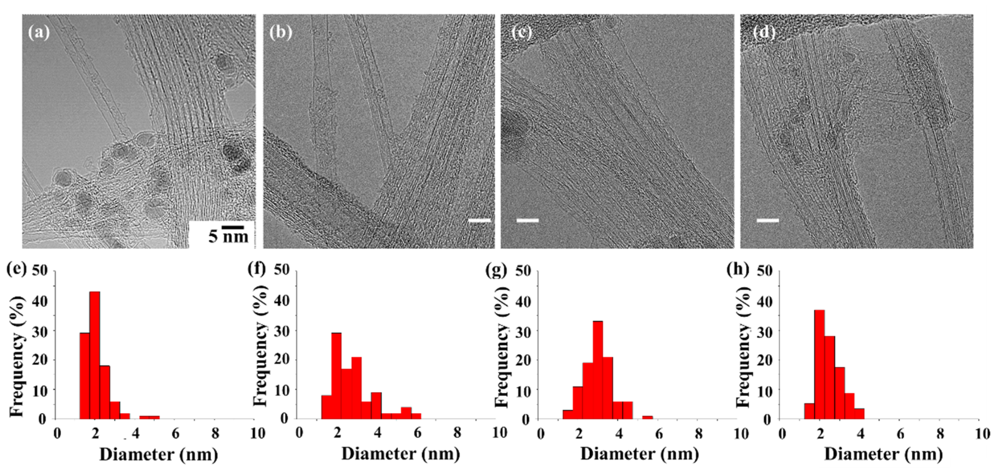
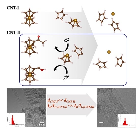
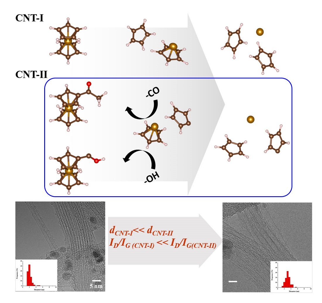
In this study, large-scale, high-quality single-walled CNT (SWCNT) and a few-walled CNT (FWCNT) with a narrow-diameter distribution were synthesized by FC-CVD. All synthesis conditions were the same except for types of catalyst precursors. The synthesized CNTs almost showed SWCNTs, but the acetylferrocene-based product shows SWCNTs and a few FWCNTs (
Figure 1). The CNT diameters exhibited their narrowest distribution with ferrocene. After sufficient dispersion by sonication, 100 CNTs were selected for each sample and the diameter distribution was analyzed. When the CNT was synthesized with ferrocene, the tube diameter (d) ranged from 1.1 to 4.8 nm; however, most of the d existed at 1~2.5 nm. When the CNT was synthesized with acetylferrocene, the distribution range of d was increased and measured between 1.5 and 6 nm, with most falling in the range of 1.5~3 nm. The synthesized CNT shows a mixed structure with SWCNT and FWCNTs. Meanwhile, when CNT was synthesized with ferrocenemethanol, the size distribution narrowed and d decreased to between 1.5 and 5.1 nm, with a large portion being in the range of 2.5~3.5 nm. The average diameter was larger than that using ferrocene. When the CNT was synthesized with 1,1′-diacetylferrocene, the diameter was found to be between 1.5 and 3.6 nm, and a substantial portion fell in the range of 2~3 nm. The tube diameter decreased less than for other ferrocene-derived catalysts.
As a result of classifying the types of synthesized CNTs by precursor, the synthesized CNTs are mostly SWCNTs, but other types of CNTs such as FWCNTs and MWCNTs also exist (
Figure S2). For acetylferrocene, the proportion of FWCNTs is increased compared to other precursors. This confirms the possibility of synthesizing other types of CNTs such as DWCNTs. In addition, in the case of ferrocenemethanol, many structures were found in which the double wall of the intermediate formation process was piled up on the outer wall of the SWCNT. Therefore, it was included as SWCNT, but there is ambiguity in the classification process. In the case of 1,1′-diacetylferrocene, the yield of the tube itself was significantly lower than that of other precursors. In the case of 1,1′-diacetylferrocene, the yield of the tube itself was significantly lower than that of other precursors, but the synthesized CNTs were mostly SWCNTs. In addition, there were many tube-shaped carbon laminates, but they were excluded from the number of tubes.
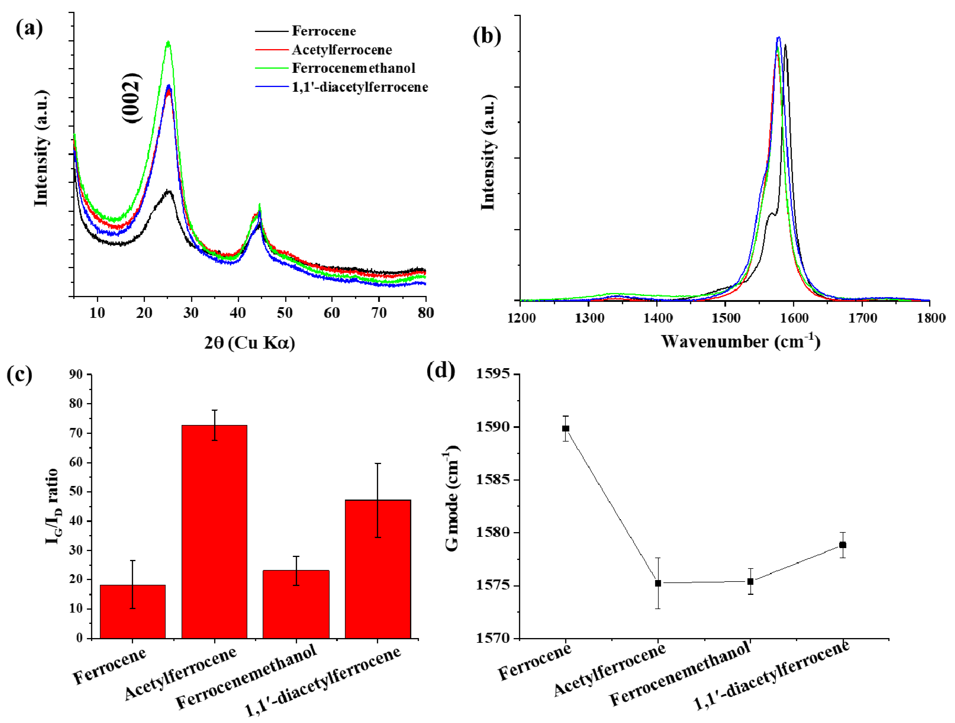
The as-synthesized CNTs showed high crystallinity and all samples showed two main peaks between 1000 cm
−1 and 2000 cm
−1, which corresponded to the D-band and the G-band (sp
2) [
19,
20,
21]. The high I
G/I
D ratio was observed in acetylferrocene (I
G/I
D = 74.43) (
Figure 2). The I
G/I
D ratios for ferrocenemethanol and 1,1′-diacetylferrocene were 23.06 and 47.12, respectively, each of which was larger than the value when ferrocene was used (I
G/I
D = 18.31). The different pyrolytic reactions caused by using different catalyst precursors are thought to have produced catalysts more suitable for CNT growth. The best CNT synthesis was observed for acetylferrocene. The G-mode caused by the bond stretching of all pairs of sp
2 atoms in both rings and chains. The peak shift of the G-mode can be associated with axial elongation/shortening of the C–C bonds in a nanotube shell. In case of SWCNT, the G band shift also related with diameter. The G-mode peaks down shifted by approximately 16 cm
−1 with catalyst precursors. In addition, C (002) peak on XRD patterns from ferrocene derived samples increased compared to using ferrocene, which means increasing crystallinity.
The radial breathing mode (RBM) of Raman spectra correspond to the atomic vibration of the C atoms in the radial direction. It is used to define the diameter of SWCNTs. The bundle of SWCNT diameters according to the expression [
22]:
where
is the RBM Raman shift, and
dt is diameter. The RBM spectra of all samples shows in
Figure S3. RBM peaks were measured at 20 positions for each sample, and were fitted with Lorentzian. The bundled nanotube fibers have broad RBMs, and it is difficult to trace all the peaks corresponding to each individual CNT that will be present [
23]. The broad RBMs have emerged due to the microstructure of heavily bundled nanotubes with varying diameters. In the case of acetylferrocene, the entire peak position shifts to a lower band compared to ferrocene, which means that the diameter of CNTs is larger than that of ferrocene. The diameter was calculated in the range of 1.0–2.25 nm by Equation (1). For ferrocene, the calculated diameter ranged from 0.9–1.6 nm, and for ferrocenemethanol it was in the range from 1.0–2.3 nm. In the case of 1,1′-diacetylferrocene, the diameter was in the range of 1.0–1.7 nm. The difference between the CNT diameter measured using the measurement software (image J) in the TEM image and the value measured using the Raman RBM is thought to be due to the inability to fit the peaks for all individual CNTs in the broad RBM peak as described above [
23]. In addition, in the case of carbon nanotubes measured by a TEM image, the average value calculated by being measured in a range of all sizes may increase. However, in the case of RBM, the peaks less than 100 cm
−1 are not measured, which may cause errors. However, as can be seen from the TEM image, it was confirmed that the diameter of CNTs using the ferrocene-derived precursor was larger than that of ferrocene.
A thermo-gravimetric (TG) analysis is used to indicate the purity and degree of graphitization of CNT structures. The results show that the amounts of residual mass decreased from 21 to 10% depending on the catalyst precursors (
Figure S4). Moreover, the thermal-decomposition temperature increased with ferrocene-derived catalysts except for 1,1′-diacetylferrocene. The high-purity CNTs that appear in the cases of acetylferrocene and ferrocenemethanol have the lowest amount of residual mass (10%). The pyrolysis of ferrocenemethanol was higher than that of acetylferrocene because of CNT structures. Liew et al. [
24] reported the thermal stability of SWCNT and MWCNTs; they found that SWCNTs are thermally more stable than MWCNTs. Because atoms from different layers start to vibrate at high temperature and atoms from one layer collide with those from the neighboring layers, it is easier for the MWCNTs to be destroyed. In their study, simulations also indicate that the CNTs with larger diameter are also more resistant to thermal loads. Therefore, CNTs synthesized using ferrocene-derived catalyst precursors are more thermally stable than the ferrocene used. Meanwhile, when we used 1,1′-diacetylferrocene, the CNTs showed faster pyrolysis than in other cases because there exist both SWCNTs and tube-like carbon-stacking agglomerate (
Figure S5).
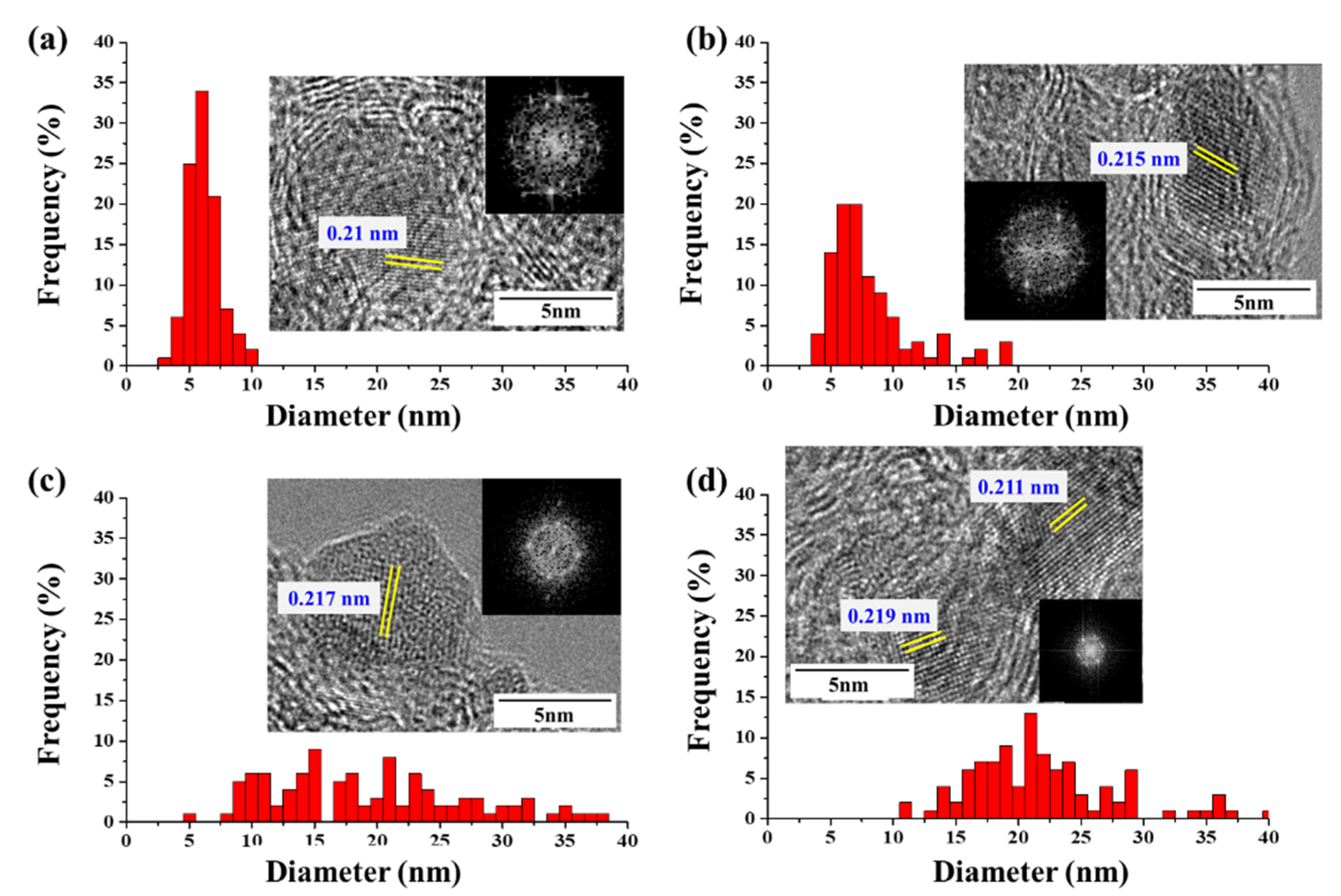
The diameters and lengths of CNTs are known to be related to the size and structure of the catalyst particles. We measured the catalyst-particle-size distributions in the CNT bundle (
Figure 3); when CNTs were synthesized using ferrocene, the catalyst particles had a size distribution between 2 and 10 nm, but most were under 7 nm. When the CNT was synthesized using acetylferrocene, the catalyst particles measured between 3.59 and 19.04 nm and the distribution range was broadened compared to that obtained with ferrocene. However, most particles had diameters between 4 nm and 8 nm with an average size of approximately 7.72 nm similar to that of ferrocene. Meanwhile, when CNTs were synthesized using ferrocenemethanol, the particle size was between 5 and 38 nm with a wide distribution range. The average size increased significantly to 18.97 nm. By contrast, at 1,1′-diacetylferrocene, the particle sizes also increased, and the distribution was broad, falling in the range of 11~40 nm. However, most particle sizes were between 17 nm and 24 nm. If the size of the catalyst particles was too large, they were not expected to grow high-quality SWCNTs. This result explains why FWCNT productivity was increased using acetylferrocene. On the other hand, particles produced with ferrocenemethanol are strongly faceted, with sharp corners, while the particles produced with ferrocene, acetylferrocene, and 1,1′-diacetylferrocene were rounded. Yamada et al. [
25] observed the alteration of carbon-coated Fe catalysts into flatter particles upon the removal of the carbon coating by water treatment. The –OH group on ferrocenmethanol reacts like water molecules in water-assisted CVD to aid in the growth of nanotubes and control particle shape. On the other hand, acetylferrocene produced C=O during decompositions. Dee et al. reported the benefits of using controlled exposure to carbon for catalyst reduction by carbothermal reduction. Preloading carbon accelerates catalyst-nanoparticle formation via film dewetting and inhibits Ostwald ripening, thereby increasing the probability of CNT nucleation and the resultant density of the CNT population [
26]. Thus, preloaded carbon might extend the lifetime of the catalyst nanoparticles by reduction of iron oxide (Fe
xO
y), which does not allow for this pathway to catalyst deactivation. Additionally, the lattice spacing of the catalyst with acetylferrocene showed 0.215 nm, which correspond to γ-Fe. Wirth et al. reported that the additional preloading carbon can be diffused into Fe and formed meta-stable γ-Fe phase [
27,
28]. However, over preload carbon species enhanced particle formation and graphitic encapsulation. As a result of that 1,1′-diacetylferrocene showed many of graphitic layer capped catalyst particles because of their double function groups. Additionally, the molecular oxygen generation will preferentially react with smaller diameters with larger curvature due to the weakened C-C bonding induced by bond bending [
26]. Thus, the SWCNTs with small diameters were removed and the CNT showed a large diameter when we used acetylferrocene and ferrocenemethanol.
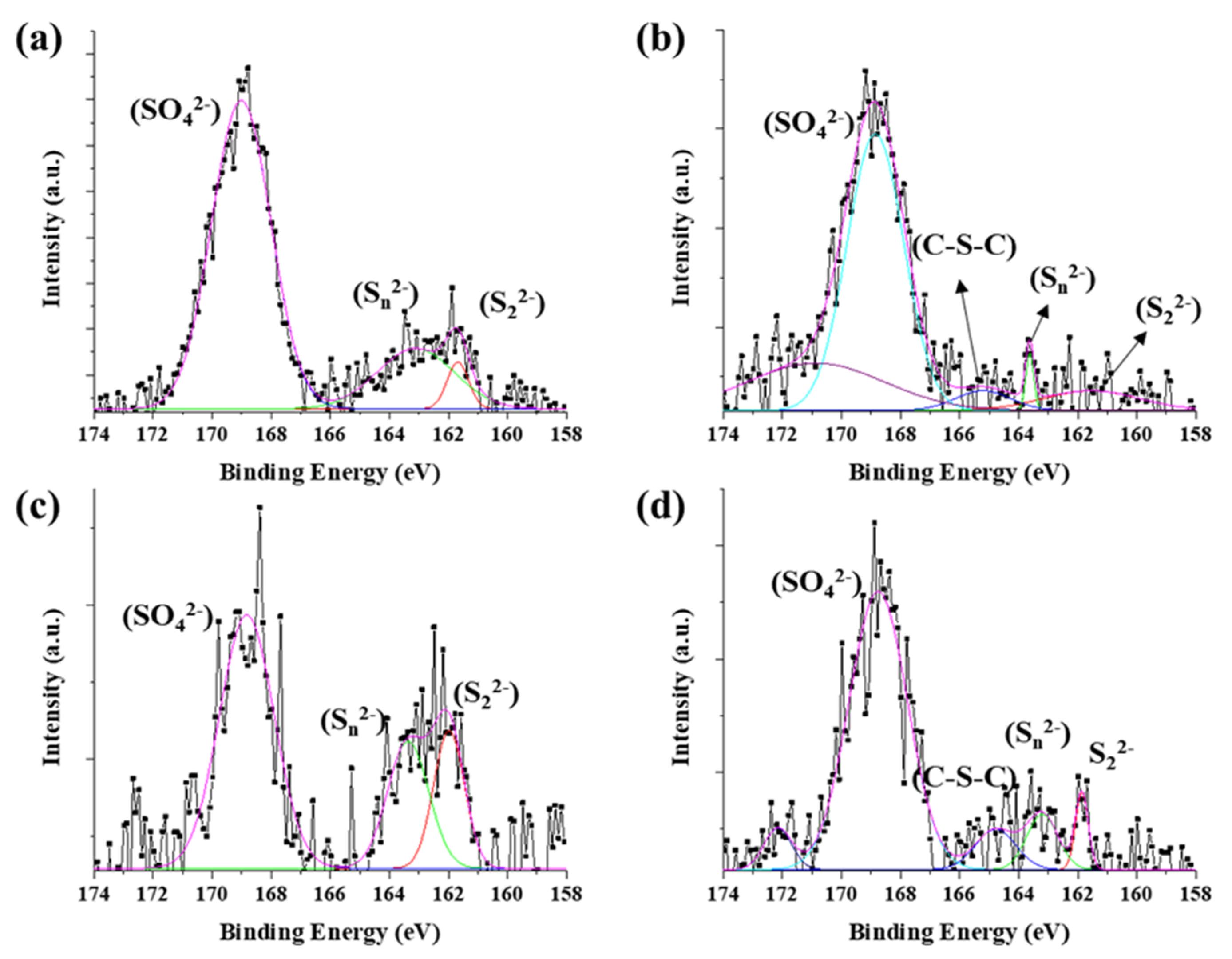
The chemical state of synthesized byproduct is also related to catalytic activity. The surface chemical states of the catalyst particles in CNT bundle were identified by X-ray photoelectron spectroscopy (XPS) (
Figure 4). The peaks were analyzed by Gaussian peak fitting. The Fe 2p 3/2 and Fe 2p 1/2 orbitals were identified as corresponding to the peaks at 710 eV and 724 eV, respectively (
Figure S6). The Fe 2p 3/2 could be divide into three peaks at biding energies of 707.7 eV, 709.8 eV, and 711.1 eV. The peaks assigned to Fe(II)-S (707.1 eV), and Fe(III)-S (709.8 eV, and 711.1 eV). The S 2p shows more complex state with acetylferrocene and 1,1′-diacetylferrocene compared with ferrocene and ferrocenemethanol, which assigned to 161.5 eV (S
2−), 163.48 eV (
), 165.2 eV (C-S-C), and 168.8 eV (
) (
Figure 4b). The sulfate highly appeared in surface than ferrocene. Only these two precursors have a C-S-C (165.2 eV) bond unlike other precursors. It can be considered that the acetyl group (CH
3CO) possessed by the precursor had an effect on the formation of the catalyst particles.
However, ferrocenemethanol mainly formed metal-sulfur bonds (such as S
2− and
) than others. It means the –OH groups react the same as water molecules which prohibit oxidation. Therefore, ferrocenemethanol shows a lower oxidation state than the other catalysts. However, the formation of the predominant metal-sulfur bond reduced the activity of the catalyst for synthesizing CNTs and reduced the diffusion rate of carbon. In a previous study [
29], it was confirmed that the oxidized state of iron sulfide helps CNT growth, but the fully crystallized to FeS
2 could not role of catalyst for CNT growth. The sulfur-metal peaks increase in the following order: ferrocenemethanol > ferrocene > 1,1′- diacetylferrocene > aetylferrocene. On the other hand, in the case of 1,1′-diacetylferrocene, the catalytic activity was reduced compared to acetylferrocene during catalyst nucleation due to initial carbon contamination under the influence of the acetyl group, which was confirmed by the appearance of many C-S-C bonds.
The catalyst particles were formed by two steps in our experiment; decomposition of the catalyst precursor (Fe) and promoter (S), followed by recrystallization of Fe-S compounds. To understand why the ferrocene-derived catalyst precursor enhanced the properties, nucleation, and growth of CNTs, the catalyst-decomposition process was investigated herein through TG-DSC. However, thiophene is not suitable for TG-DSC experiments because of its high volatility; therefore, sulfur was used as the source of S, rather than thiophene.
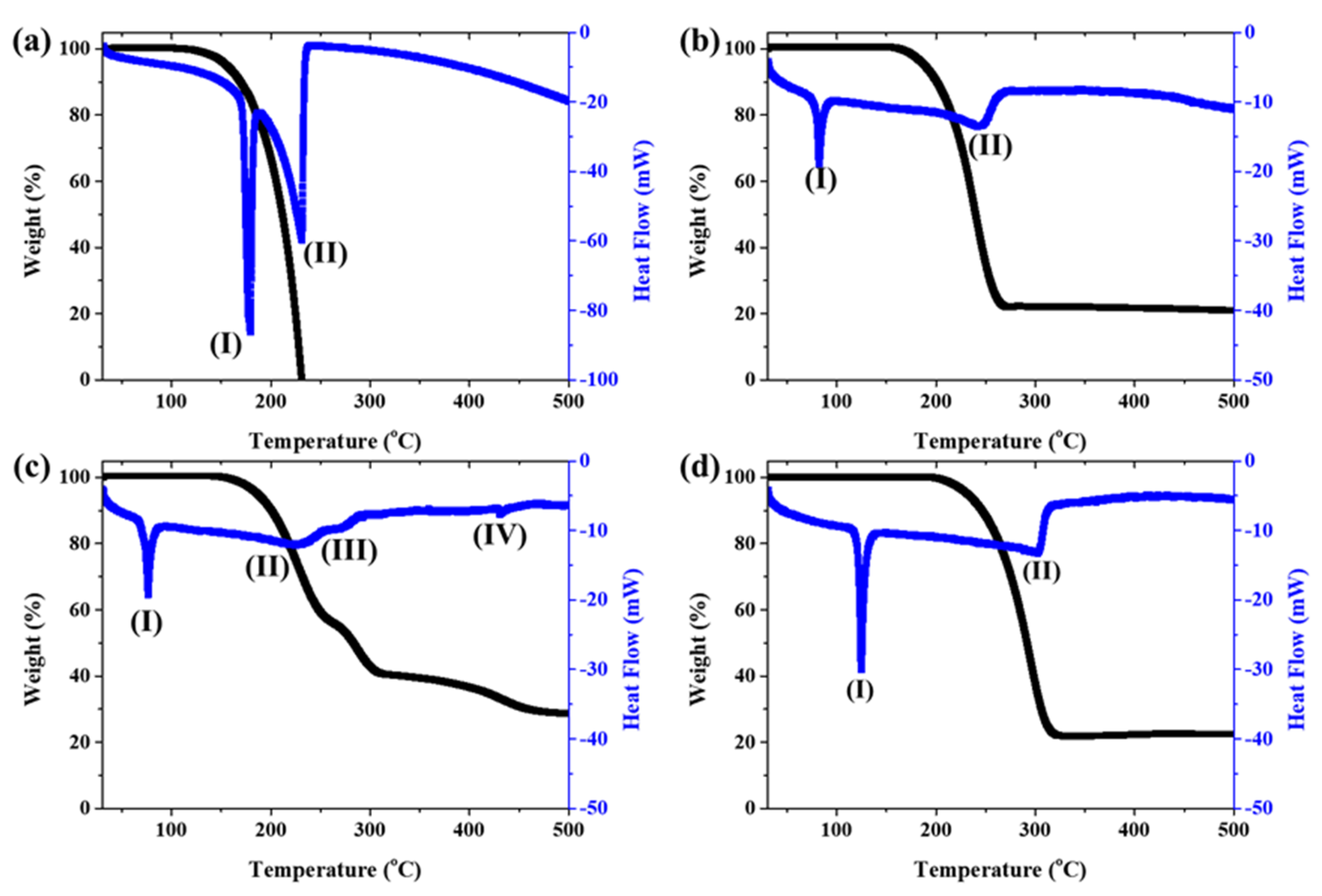
At first, only ferrocene and ferrocene-derived precursors without sulfur were analyzed for TG-DSC up to 600 °C (
Figure 5). Additionally, bond dissociation energy was calculated by DFT simulations to track the catalyst’s decomposition mechanism (
Figure 6). The endothermic reaction appears at 178 °C (
Figure 5a(I)) and 231 °C (
Figure 5a(II)) in ferrocene. This temperature range is due to the sublimation reaction. Ferrocene decomposes above 497 °C to form a metallic ion, indicating that solid or liquid-like Fe particles and different kinds of species exist in the pyrolysis. However, the amount of sample remaining after sublimation is too small to confirm the next step of pyrolysis, so it cannot be confirmed with TG.
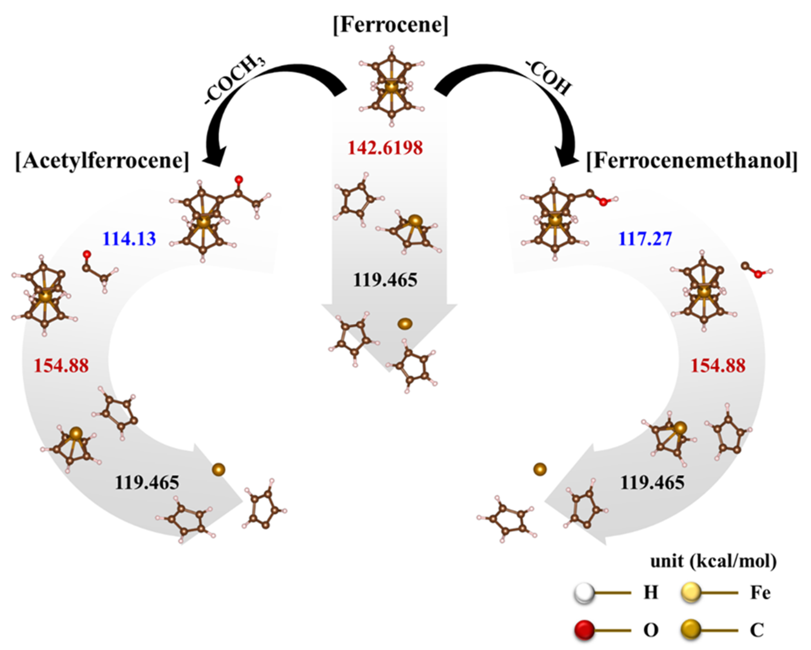
However, the calculated bond-dissociation energies are 142.62 kcal/mol and 119.5 kcal/mol, which correspond to the dissociation of C
p ligands in the first and second layers, respectively [
30,
31]. The first dissociating C
p ligand needs to have a higher energy than the second layer. Thus, the ferrocene-dissociation mechanism involves the heterolytic dissociation according to the following steps:
On the other hand, ferrocene derived catalysts show more complex pyrolysis reactions. The first endothermic reactions in acetylferrocene and ferrocenemethanol occurred at 83 °C (
Figure 5b(I)) and 77 °C (
Figure 5c(I)), and the second endothermic reactions appeared at 246 °C (
Figure 5b(II) and 226 °C (
Figure 5c(II)), respectively. Unlike the first endothermic reaction, the second reaction of acetylferrocene occurred later than that of ferrocenemethanol. In addition, ferrocenemethanol undergoes another endothermic reaction at 270 °C (
Figure 5c(III)). The ferrocene-derived catalyst precursor firstly dissociated the functional groups such as CH
3CO and COH from the ferrocene structure. The dissociation-binding energies of acetylferrocene and ferrocenemethanol were 114.14 kcal/mol and 117.27 kcal/mol, and the first-layer dissociation energy after detachment of the functional groups was 154.88 kcal/mol. This suggests that more energy is needed to decompose than ferrocene (142.62 kcal/mol). Thus, the ferrocene-derived precursors decomposed at a higher temperature than did ferrocene. The decomposition process of each precursor with bond dissociation shows
Figure 6. We assumed that, if the thermal-decomposition temperature of the catalyst precursor was high, the decomposition time would be delayed, affecting the formation of catalyst particles and thus making smaller catalyst particles. Indeed, the pyrolysis and release of Fe ions were delayed by the functional groups of ferrocene-derived precursors, which were related to the bond-dissociation energy. However, the catalyst-size distribution and average diameter of the ferrocene-derived precursors were broader and larger than those of ferrocene itself. In general, the reactivity of a catalyst decreases as its size increases, resulting in low nucleation and growth. However, in our case, it was possible to synthesize a highly crystalline CNT despite the large catalyst particles. Therefore, we believe that the chemical state and crystalline structure of the catalyst particles plays a more important role in the formation of CNTs because of the addition of sulfur.
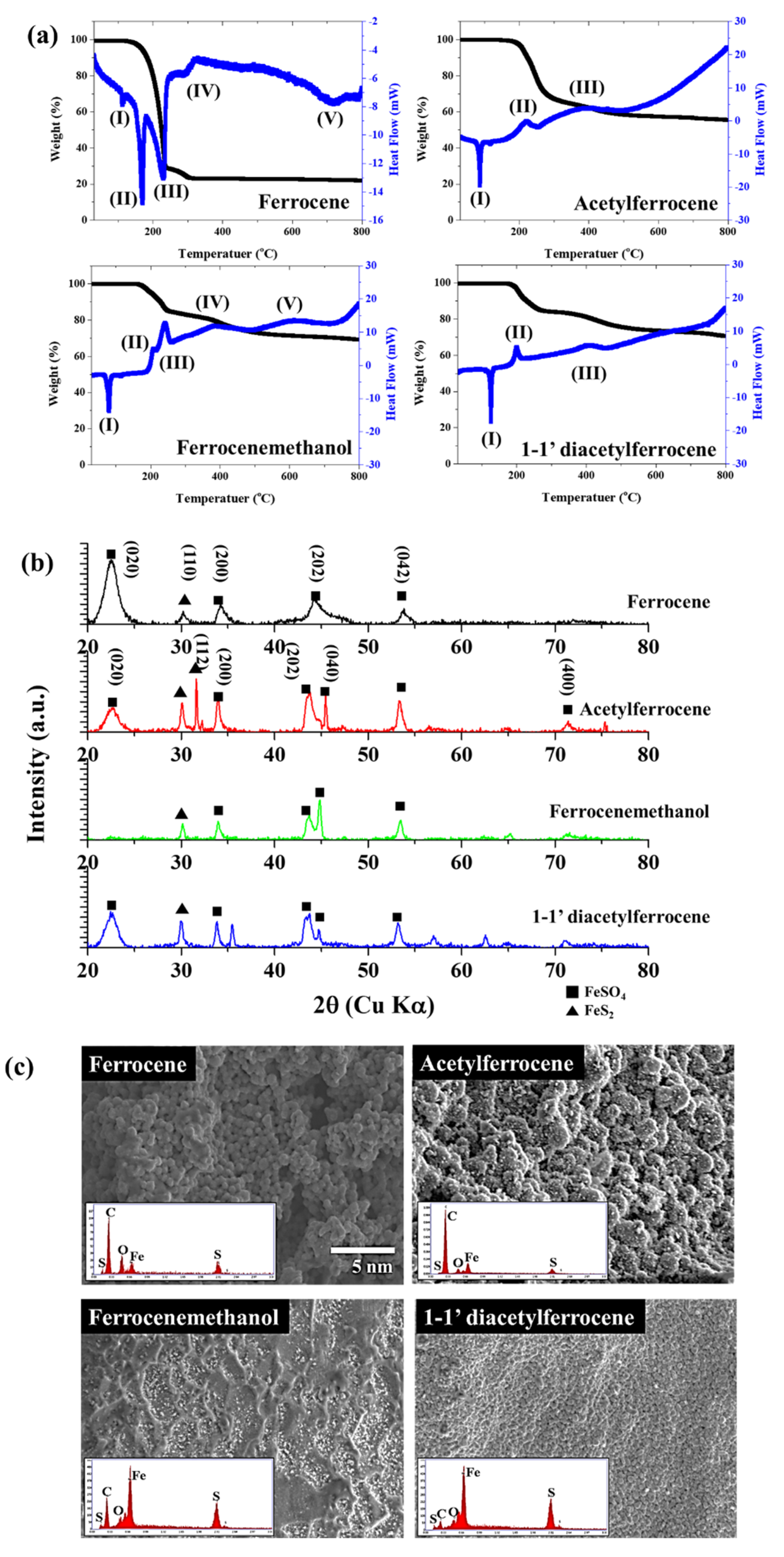
To confirm the reactivity with sulfur during pyrolysis, all catalyst precursors were pyrolyzed with sulfur (Fe:S = 1:1 (at %)) up to 800 °C. The states of the formed particles between ferrocene-thiophene and ferrocene-sulfur are different, but the reactivity with sulfur atoms can be estimated. The generation of secondary species differed according to the oxygen containing functional group on the precursors. The crystalline structures were examined by X-ray diffraction (XRD) (
Figure 7b), and the catalyst particles in ferrocene-sulfur system were well-assigned to FeSO
4 (JCPDS No. 12-0068). However, other ferrocene-derived catalysts show mixed structures, which indexed FeSO
4 (JCPDS No. 12-0068) and FeS
2 (JCPDS No. 2-0908). The newly formed FeS
2 nuclei further grow into nanoparticles, and the ferrocene-derived precursors react rapidly with sulfur to form sulfur compounds unlike ferrocene. Thus, the concentration of residual compounds increased compared with ferrocene. Exothermic peaks appear at 222 °C (
Figure 7a(II)), 240 °C (
Figure 7a(II,III), and 200 °C (
Figure 7a(II)), corresponding to acetylferrocene, ferrocenemethanol, and 1,1′-diacetylferrocene, respectively. This exothermic peak means that crystallization and oxidation of the mixed compounds occurs faster than the reaction of ferrocene at 320 °C. Fe
2+ ions are generated, and sulfur ions and un-reacted sulfur will immediately combine with them to form FeS
2 [
29]. The DSC of elemental sulfur mainly comprises three endothermic signals: the α→β transition of sulfur at around 100 °C, the melting at ~120 °C, and the λ-transition, which starts at ~160 °C. The sulfur was completely sublimated at ~330 °C [
32]. The reaction of ferrocene-derived precursors with sulfur occurs as follows: first, the functional group detaches from the precursors; then, melted sulfur reacts with unsaturated ferrocene-derived molecules; finally, sublimation and recrystallization occur. The synthesized catalyst particles aggregate and form a non- spherical morphology in contrast to what happens for ferrocene, because it is driven by the minimization of interfacial energy. Thus, the average diameters of the ferrocene-derived precursors are broader and larger than those formed from ferrocene.
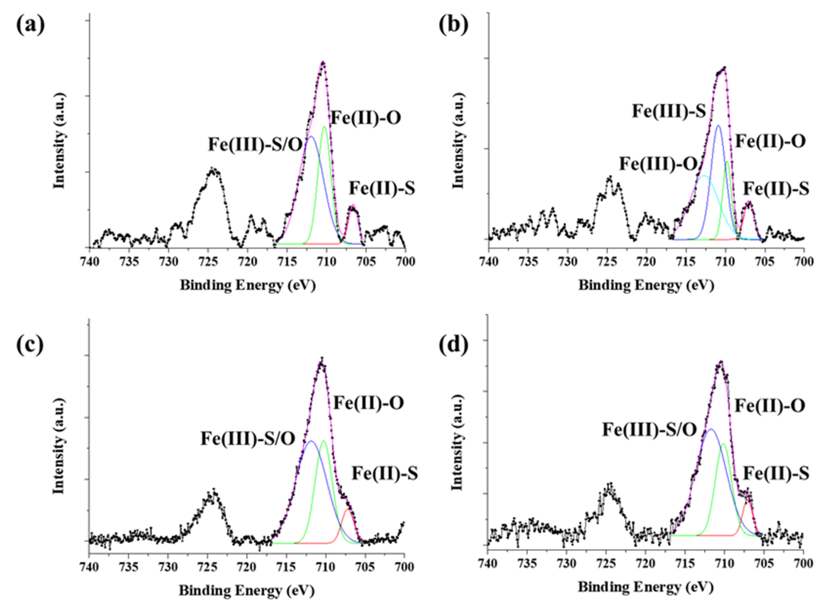
The chemical state of synthesized byproduct is also related to catalytic activity. The surface chemical states of the catalyst particles were identified by X-ray photoelectron spectroscopy (XPS) (
Figure 8). The Fe 2p 3/2 and Fe 2p ½ orbitals were identified as corresponding to the peaks at 710 eV and 724 eV, respectively. The peaks were analyzed by Gaussian peak fitting and assigned to Fe
2+ and Fe
3+. For ferrocene, three peaks at 706.6 eV (Fe(II)-S), 710.3 eV (Fe(II)-O), and 711.9 eV (Fe(III)-S/O) were observed; these were assigned to Fe
2+. For acetylferrocene, four peaks were observed at 707 eV (Fe(II)-S), 709.8 eV (Fe(II)-O), 710.9 eV (Fe(III)-S), and 712.7 eV (Fe(III)-O), which were assigned to mixtures Fe
2+ and Fe
3+. The generation of Fe
3+ requires an unspecified oxidative process, leaving some ambiguity as to the oxidation state of the iron formed directly from ferrocene-derived precursor dissociation [
27]. On the other hand, for ferrocenemethanol, three peaks were observed at 707.2 eV (Fe(II)-S), 710.2 eV (Fe(II)-O), and 711.8 eV (Fe(III)-S/O), for which the chemical state was similar to that of ferrocene. 1,1′-diacetylferrocene also shows results similar to those of ferrocene and ferrocenemethanol, which assigned as 707.11 eV (Fe(II)-S), 710.2 eV (Fe(II)-O), 711.7 eV (Fe(III)-S/O). The S 2p shows more complex state with acetylferrocene and 1,1′-diacetylferrocene compared with ferrocene and ferrocenemethanol, which assigned to 160.92 eV (S
2−), 162.11 eV (
), 163.48 eV (
), 164.58 eV (S
0), and 167.90 eV (
) (
Figure S7). The oxidation form highly appeared in the surface than ferrocene. However, ferrocenemethanol mainly formed metal–sulfur bonds (such as S
2− and
) than others. It means the –OH groups react as water molecules which prohibit oxidation. Therefore, ferrocenemethanol shows a lower oxidation state than the other catalysts. As we mentioned previously, ferrocene and ferrocene derived precursors produce various substances upon pyrolysis. These substances affect when it combines with the decomposed sulfur to form catalyst particles. In the process of synthesizing CNTs in which a carbon source is actually supplied, functional groups derived from ferrocene help to activate the catalyst, but when only pyrolysis of the catalyst was observed in an inert atmosphere, these functional groups acted as sources to form compounds. However, it was confirmed that the functional groups of the initial catalyst precursor control the reactivity of iron ions and the structure of the catalyst.


