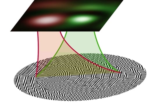
Ultra-Thin, Short-Focus, and High-Aperture Metalens for Generating and Detecting Laser Optical Vortices
Abstract
:1. Introduction
2. Theoretical Background
3. Simulation of TC Detection
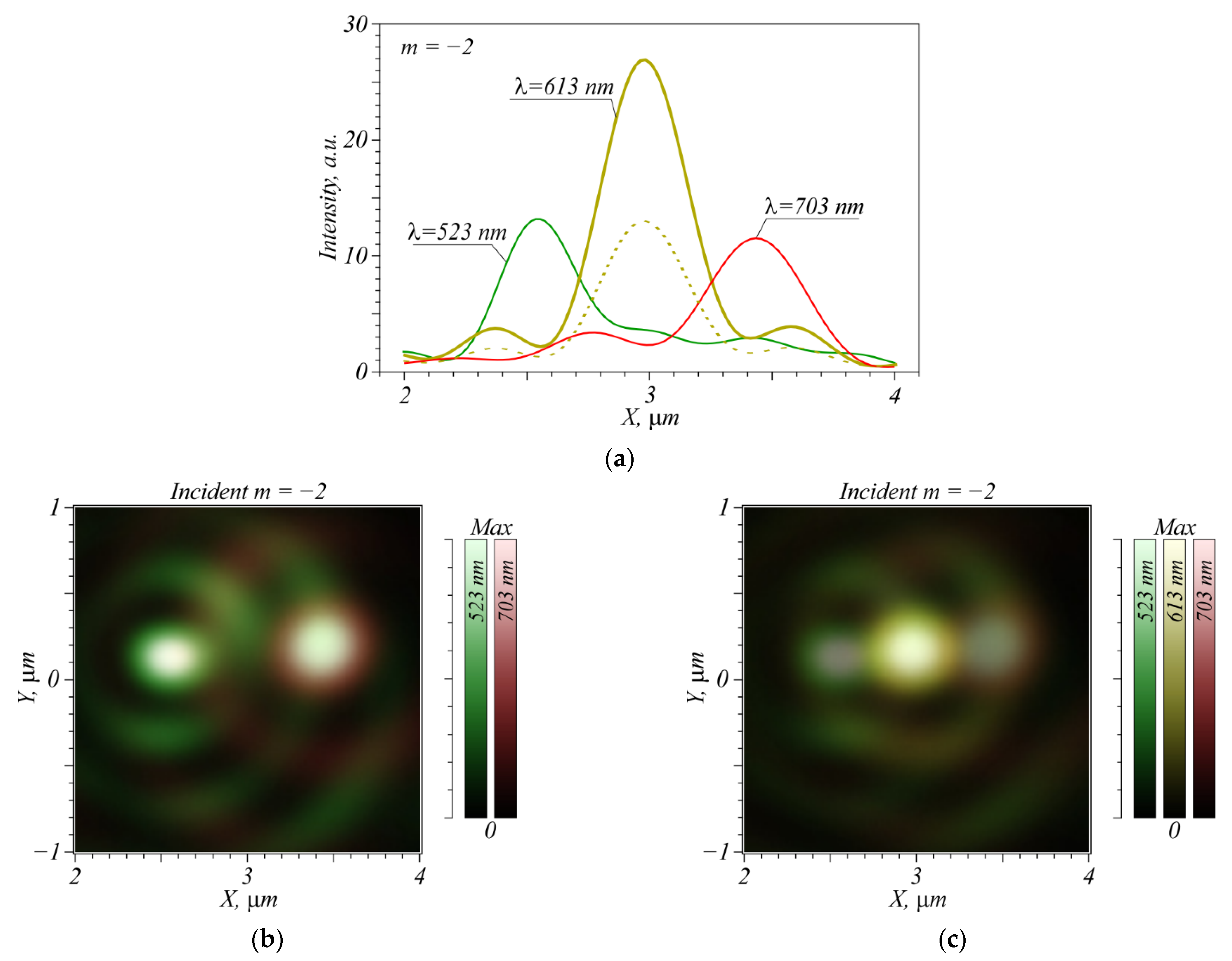
4. Numerical Simulation of Metalens-Aided Focusing of Different Incident Wavelengths
5. Conclusions
Author Contributions
Funding
Data Availability Statement
Acknowledgments
Conflicts of Interest
References
- Wang, W.; Guo, Z.; Zhou, K.; Sun, Y.; Shen, F.; Li, Y.; Qu, S.; Liu, S. Polarization-independent longitudinal multi-focusing metalens. Opt. Express 2015, 23, 29855–29866. [Google Scholar] [CrossRef] [PubMed]
- Tian, S.; Guo, H.; Hu, J.; Zhuang, S. Dielectric longitudinal bifocal metalens with adjustable intensity and high focusing efficiency. Opt. Express 2019, 27, 680–688. [Google Scholar] [CrossRef] [PubMed]
- Kim, C.; Kim, S.; Lee, B. Doublet metalens design for high numerical aperture and simultaneous correction of chromatic and monochromatic aberrations. Opt. Express 2020, 28, 18059–18076. [Google Scholar] [CrossRef] [PubMed]
- Li, M.; Li, S.; Chin, L.; Yu, Y.; Tsai, D.; Chen, R. Dual-layer achromatic metalens design with an effective Abbe number. Opt. Express 2020, 28, 26041–26055. [Google Scholar] [CrossRef]
- Hsiao, H.-H.; Chu, C.H.; Tsai, D.P. Fundamentals and applications of metasurfaces. Small Methods 2017, 1, 1600064. [Google Scholar] [CrossRef] [Green Version]
- Shan, D.; Xu, N.; Gao, J.; Song, N.; Liu, H.; Tang, Y.; Feng, X.; Wang, Y.; Zhao, Y.; Chen, X.; et al. Design of the all-silicon long-wavelength infrared achromatic metalens based on deep silicon etching. Opt. Express 2022, 30, 13616–13629. [Google Scholar] [CrossRef] [PubMed]
- Chantakit, T.; Schlickriede, C.; Sain, B.; Meyer, F.; Weiss, T.; Chattham, N.; Zentgraf, T. All-dielectric silicon metalens for two-dimensional particle manipulation in optical tweezers. Photon. Res. 2020, 8, 1435–1440. [Google Scholar] [CrossRef]
- Fan, C.; Chuang, T.; Wu, K.; Su, G. Electrically modulated varifocal metalens combined with twisted nematic liquid crystals. Opt. Express 2020, 28, 10609–10617. [Google Scholar] [CrossRef] [PubMed]
- Ma, X.; He, W.; Xin, L.; Yang, Z.; Liu, Z. Imaging performance of a mid-infrared metalens with a machining error. Appl. Opt. 2022, 61, 60–68. [Google Scholar] [CrossRef]
- Qian, Z.; Tian, S.; Zhou, W.; Wang, J.; Guo, H. Broadband achromatic longitudinal bifocal metalens in the visible range based on a single nanofin unit cell. Opt. Express 2022, 30, 11203–11216. [Google Scholar] [CrossRef]
- Xie, Y.; Zhang, J.; Wang, S.; Liu, D.; Wu, X. Broadband polarization-insensitive metalens integrated with a charge-coupled device in the short-wave near-infrared range. Opt. Express 2022, 30, 11372–11383. [Google Scholar] [CrossRef]
- Hsiao, H.-H.; Chen, Y.H.; Lin, R.J.; Wu, P.C.; Wang, S.; Chen, B.H.; Tsai, D.P. Integrated resonant unit of metasurfaces for broadband efficiency and phase manipulation. Adv. Opt. Mater. 2018, 6, 1800031. [Google Scholar] [CrossRef]
- Liu, M.; Cao, J.; Xu, N.; Wang, B. Broadband achromatic metalens for linearly polarized light from 450 to 800 nm. Appl. Opt. 2021, 60, 9525–9529. [Google Scholar] [CrossRef]
- Wang, W.; Guo, Z.; Li, R.; Zhang, J.; Liu, Y.; Wang, X.; Qu, S. Ultra-thin, planar, broadband, dual-polarity plasmonic metalens. Photon. Res. 2015, 3, 68–71. [Google Scholar] [CrossRef] [Green Version]
- Ye, H.; Sun, Q.; Guo, Z.; Hou, Y.; Wen, F.; Yuan, D.; Qin, F.; Zhou, G. Theoretical realization of single-mode fiber integrated metalens for beam collimating. Opt. Express 2021, 29, 27521–27529. [Google Scholar] [CrossRef] [PubMed]
- Wang, G.; Habib, U.; Yan, Z.; Gomes, N.; Sui, Q.; Wang, J.; Zhang, L.; Wang, C. Highly efficient optical beam steering using an in-fiber diffraction grating for full duplex indoor optical wireless communication. J. Lightwave Technol. 2018, 36, 4618–4625. [Google Scholar] [CrossRef] [Green Version]
- Shen, Z.; Xiang, Z.; Wang, Z.; Shen, Y.; Zhang, B. Optical spanner for nanoparticle rotation with focused optical vortex generated through a Pancharatnam–Berry phase metalens. Appl. Opt. 2021, 60, 4820–4826. [Google Scholar] [CrossRef]
- Guo, Y.; Zhang, S.; Luo, X. Spin-decoupled metasurface for simultaneous detection of spin and orbital angular momenta via momentum transformation. Light Sci. Appl. 2021, 10, 63. [Google Scholar] [CrossRef] [PubMed]
- Jin, Z.; Janoschka, D.; Deng, J.; Ge, L.; Dreher, P.; Frank, B.; Hu, G.; Ni, J.; Yang, Y.; Li, J.; et al. Phyllotaxis-inspired nanosieves with multiplexed orbital angular momentum. eLight 2021, 1, 5. [Google Scholar] [CrossRef]
- Kotlyar, V.V.; Stafeev, S.S.; Nalimov, A.G.; O’Faolain, L.; Kotlyar, M.V. A dual-functionality metalens to shape a circularly polarized optical vortex or a second-order cylindrical vector beam. Phot. Nanostr. Fund. Appl. 2021, 43, 100898. [Google Scholar] [CrossRef]
- Zeng, J.; Li, L.; Yang, X.; Gao, J. Generating and separating twisted light by gradient–rotation split-ring antenna metasurfaces. Nano Lett. 2016, 16, 3101–3108. [Google Scholar] [CrossRef] [PubMed]
- Mehmood, M.Q.; Mei, S.; Hussain, S.; Huang, K.; Siew, S.Y.; Zhang, L.; Zhang, T.; Ling, X.; Liu, H.; Teng, J.; et al. Visible-frequency metasurface for structuring and spatially multiplexing optical vortices. Adv. Mater. 2016, 28, 2533–2539. [Google Scholar] [CrossRef] [PubMed]
- Kotlyar, V.V.; Nalimov, A.G.; Stafeev, S.S.; Hu, C.; O’Faolain, L.; Kotlyar, M.V.; Gibson, D.; Song, S. Thin high numerical aperture metalens. Opt. Express 2017, 25, 8158–8167. [Google Scholar] [CrossRef] [Green Version]
- Heckenberg, N.R.; McDuff, R.; Smith, C.P.; White, A.G. Generation of optical singularities by computer-generated holograms. Opt. Lett. 1992, 17, 221–223. [Google Scholar] [CrossRef] [PubMed]
- Lalanne, P.; Lemercier-Lalanne, D. On the effective medium theory of subwavelength periodic structures. J. Mod. Opt. 1996, 43, 2063–2085. [Google Scholar] [CrossRef]
- Kotlyar, V.V.; Nalimov, A.G. A vector optical vortex generated and focused using a metalens. Comput. Opt. 2017, 41, 645–654. [Google Scholar] [CrossRef]
- Stafeev, S.S.; O’Faolain, L.; Kotlyar, V.V.; Nalimov, A.G. Tight focus of light using micropolarizer and microlens. Appl. Opt. 2015, 54, 4388–4394. [Google Scholar] [CrossRef] [PubMed] [Green Version]



Publisher’s Note: MDPI stays neutral with regard to jurisdictional claims in published maps and institutional affiliations. |
© 2022 by the authors. Licensee MDPI, Basel, Switzerland. This article is an open access article distributed under the terms and conditions of the Creative Commons Attribution (CC BY) license (https://creativecommons.org/licenses/by/4.0/).
Share and Cite
Nalimov, A.; Kotlyar, V. Ultra-Thin, Short-Focus, and High-Aperture Metalens for Generating and Detecting Laser Optical Vortices. Nanomaterials 2022, 12, 2602. https://doi.org/10.3390/nano12152602
Nalimov A, Kotlyar V. Ultra-Thin, Short-Focus, and High-Aperture Metalens for Generating and Detecting Laser Optical Vortices. Nanomaterials. 2022; 12(15):2602. https://doi.org/10.3390/nano12152602
Chicago/Turabian StyleNalimov, Anton, and Victor Kotlyar. 2022. "Ultra-Thin, Short-Focus, and High-Aperture Metalens for Generating and Detecting Laser Optical Vortices" Nanomaterials 12, no. 15: 2602. https://doi.org/10.3390/nano12152602
APA StyleNalimov, A., & Kotlyar, V. (2022). Ultra-Thin, Short-Focus, and High-Aperture Metalens for Generating and Detecting Laser Optical Vortices. Nanomaterials, 12(15), 2602. https://doi.org/10.3390/nano12152602


