1. Introduction
There is no doubt that optical wireless communication (OWC) systems have some remarkable benefits compared to radio frequency (RF) solutions [
1,
2,
3,
4]: no regulatory and license problems, rapid deployment and inexpensive operation, as well as data security and throughput, just to cite briefly the most important aspects. However, even for OWC links, the available bandwidth is not infinite, but subject to limitations because of different reasons, e.g., physical restrictions of electrical and optical elements in transmitters and receivers, dispersion effects introduced by the channel, or impairments due to multipath propagation in indoor applications. For an optical intensity link [
5], this means that the baseband pulse has to be shaped appropriately in the transmitter unit to avoid negative signal components. On the other hand, it is still appreciated that the waveform satisfies the Nyquist criterion in order to keep the detection process in the receiver module as simple as possible.
For a bandlimited OWC link, characterized by intensity modulation and direct detection (IM/DD), it was shown in [
6] that both the non-negativity and Nyquist requirements are satisfied for a squared sinc pulse; for practical reasons admitting some amount of excess bandwidth, this results in a squared raised cosine (SRC) function. It was proved in [
6] as well that a suitable root-Nyquist solution does not exist in the context of limited bandwidth, although this would be necessary to implement a matched filter (MF) in the receiver station to maximize the signal-to-noise ratio (SNR) at the detector output. As an alternative, the authors in [
7,
8] suggested that the non-negativity constraint is achieved by an offset component, although this is less efficient in terms of power, but it needs only half of the bandwidth compared to an SRC approach. Finally, a two-dimensional signal space was studied in [
9,
10] to increase the spectral efficiency of optical links.
Powerful estimation of the most important transmission parameters is key for any receiver terminal [
11,
12], which does not only hold true for radio, but also for optical scenarios. Regarding the latter, knowledge of both symbol timing and signal amplitude is of paramount importance; otherwise, subsequent stages, like detector units or error correction schemes, cannot be operated reliably. Scanning the open literature in this context, numerous contributions about channel estimation and/or symbol timing recovery are available, but they are not or only marginally related to bandwidth constraints and pulse shaping. From the author’s point of view, it is the first time that this specific problem is analyzed and discussed in a structured and non-heuristic manner for the current contribution.
The remainder of the paper is organized as follows: The signal and channel model used for analytical and simulation work is introduced in
Section 2. In
Section 3, we derive the Cramer–Rao lower bound as the theoretical limit of the error performance. Next, a maximum likelihood estimator is developed in
Section 4; since this requires a receiver MF violating the Nyquist property, a modified solution is investigated based on the implementation of a flat receiver filter. Numerical results are presented in
Section 5, and
Section 6 concludes the paper.
2. Signal and Channel Model
In the sequel, we assume that the real-valued data symbols
ak,
, are independent and identically distributed (i.i.d.) elements of an
M-ary pulse amplitude modulation (PAM) alphabet
. For convenience reasons, the alphabet is organized such that the symbols are normalized to unit energy, i.e.,
ak ∈
=
, where
. This means that the average value is given by
Furthermore, it is assumed that the pulses in the transmitter station are either shaped by a squared raised cosine (SRC) or a squared double jump (SDJ) function [
6] specified as
where sinc(
x) = sin(
πx)/(
πx), 0 ≤
α ≤ 1 is the excess bandwidth (roll-off factor), and
T stands for the symbol period the OWC link is operated with.
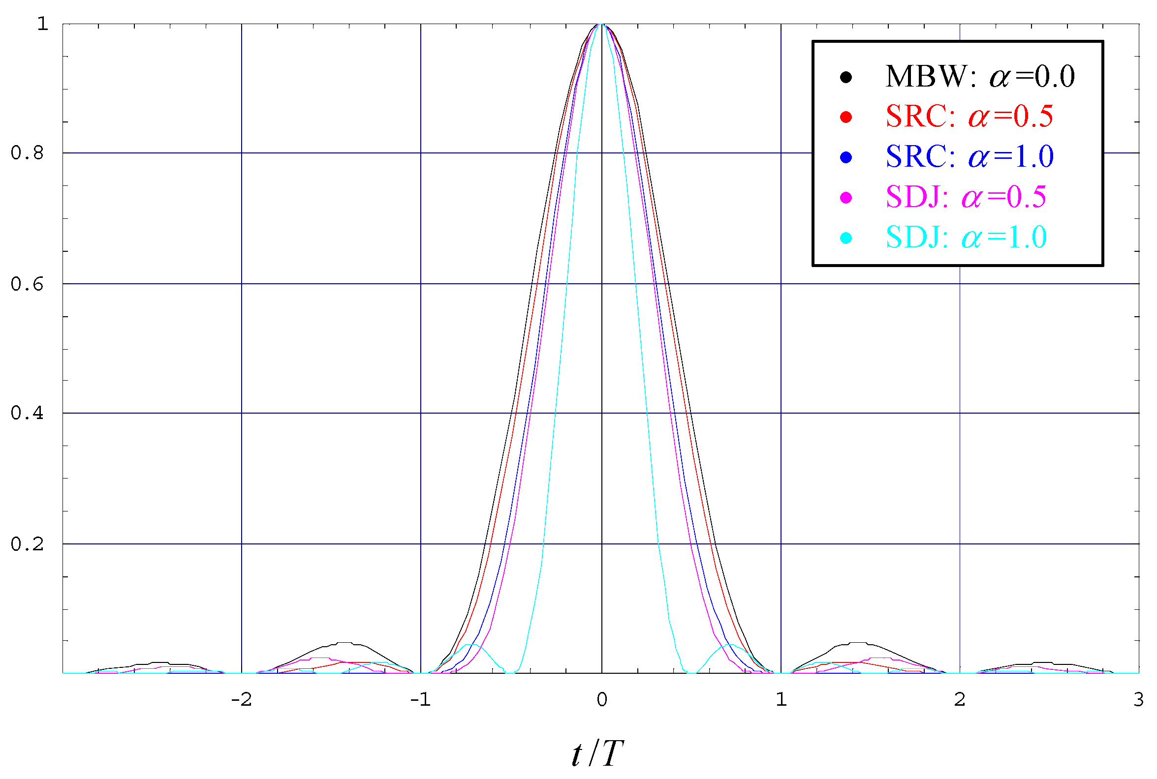
Note that SRC and SDJ shapes satisfy both the non-negativity and the Nyquist criteria, exemplified in
Figure 1 for
α ∈ {0.0, 0.5, 1.0}. Note also that SRC and SDJ are equivalent for
α = 0, which represents the minimum bandwidth (MBW) case. By detailed inspection of the plot, we observe that the width of the main lobe decreases when
α is increased and that this effect is more pronounced for SDJ scenarios.
No matter which sort of pulse shape is finally implemented, the generated transmitter signal can be written as
By introduction of the electro–optical conversion factor
K0, the irradiated signal at the output of the intensity modulator is given as
I0(
t) =
K0 s(
t). If we adopt an observation window for the estimation procedure, which is small enough so that the channel state does not change significantly over this period of time, then fading effects need not be taken into account. This means that the optical signal of interest at the receiver is only affected by some propagation loss and a delay in time, henceforth denoted by
Kl and
τ, respectively; as a result, the transfer function of the channel is obtained as
λ(
t) =
Kl δ(
t –
τ), where
δ(⋅) symbolizes Dirac’s delta function. Therefore, the optical signal intensity at the input of the receiver terminal is simply described as
I1(
t) =
λ(
t) ⊗
I0(
t) =
Kl K0 s(
t –
τ), where ⊗ denotes the convolutional operator. Specifying in the sequel the detector responsivity as
Rd, the electrical signal at the detector output is determined by
x(
t) =
Rd I1(
t) =
A⋅
s(
t –
τ), where
A =
Rd Kl K0 is the gain factor characterizing the OWC link. Finally, we have to consider that
x(
t) is distorted by additive white Gaussian noise (AWGN), in the following denoted as
w(
t), with zero mean and variance
. Putting these pieces together, the receiver signal can be expressed as
However, before being treated in further stages of operation, the signal in (4) has to pass the receiver filter
q(
t), whose output
z(
t) =
q(
t) ⊗
r(
t) is appropriately sampled to avoid alias effects. For convenience reasons, the signal and channel model used for analytical and simulation work is summarized in
Figure 2.
Before we proceed to the computation of the Cramer–Rao lower bound in the next section, it makes sense to introduce the average optical power as
, where
In addition, the average electrical SNR at the receiver is defined as
It has been proved in [
6] that the SDJ pulse is optimal insofar as
achieves a minimum for a given value of
α, which is a major motivation to compare the performance of this kind of pulse to SRC shapes.
5. Numerical Results
In the sequel, the mean estimator value (MEV) and the jitter (error) variance are discussed as the main figures of merit, when it comes to the estimation of a transmission parameter um. The former is defined as the average value of the estimates generated by the algorithm selected for this purpose. From a practical point of view, it is most helpful if this is achieved without bias, i.e., . On the other hand, for an efficient recovery algorithm, the related jitter variance should be as close to the MCRLB as possible.
For reasons of clarity and readability, analytical and simulation results will be indicated by lines and markers in different styles. Moreover, if not stated otherwise, the following parameterization is employed:
The observation window consists of L = 100 symbol periods.
We focus on the investigation of 4-PAM constellations, but the basic findings apply to M-ary PAM signals in general.
The excess bandwidth of SRC or SDJ shapes is given by α ∈ {0.0, 0.5, 1.0}.
An oversampling factor
Ns = 4 is selected; this avoids alias effects and keeps the computational load as small as possible. However, it turned out that this might be problematic for larger values of the excess bandwidth, because in this case the main lobe of the pulse shape becomes smaller (see
Figure 1) so that it is not resolved fine enough; this results in a bias effect for timing estimates, as could be verified by simulation results. Hence, for values of
α ≥ 0.5, it is suggested to apply
Ns = 8 for SRC as well as SDJ shapes.
For convenience reasons, the timing offsets τ and amplitude gains A are normalized to the nominal values of symbol period and signal amplitude, T0 and A0, respectively, as such they will be denoted by ε = τ/T0 and ρ = A/A0.
Results achieved by a matched filter or a flat filter receiver are indicated by MF and FF, respectively.
Assuming a reference index
μ = 0 for symbol timing recovery in the range of the normalized symbol period, i.e., |
ε | ≤ 1/2,
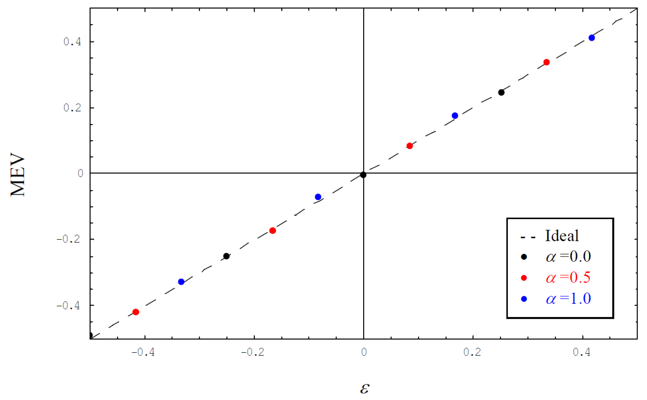
Figure 3 shows the MEV for different values of the roll-off factor applied to SRC shapes using an MF receiver. We can see that the estimator exhibits no bias, indicated by the ideal curve in dashed style. Although not shown in
Figure 3 to avoid an overload of the diagram, it could be verified that this also holds true for an FF receiver or if pulses are shaped by an SDJ function.
Of course, the algorithm for estimating the signal amplitude has been tested as well.
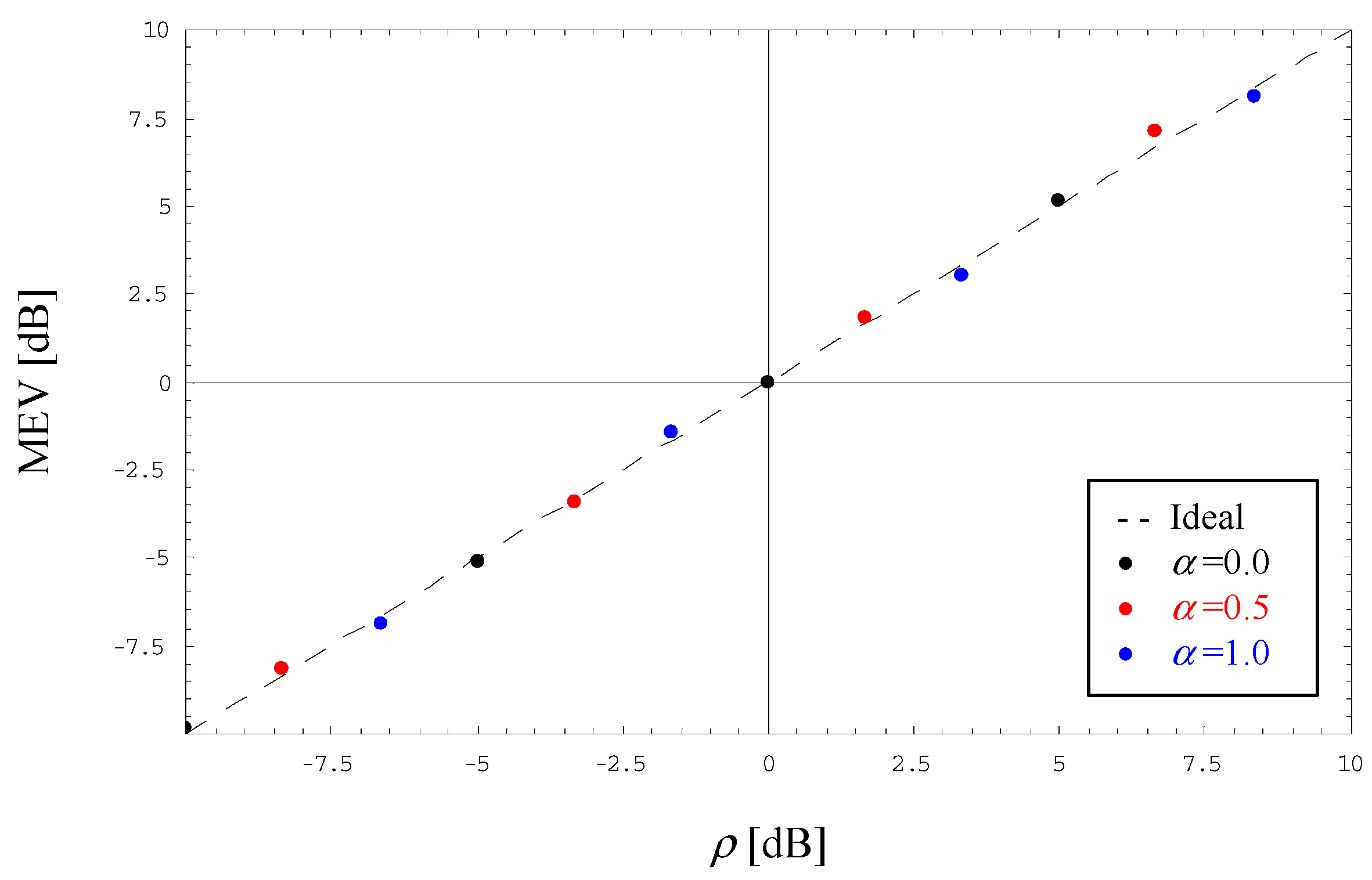
Figure 4 illustrates the MEV of the normalized amplitude estimate delivered by (27) in the range of ±10 dB for an FF scenario applied to SDJ shapes and different values of
α. Again, we observe that the estimation procedure is bias-free, which has also been tested for an MF scenario and SRC shapes.
As a function of the electrical SNR value defined in (6),
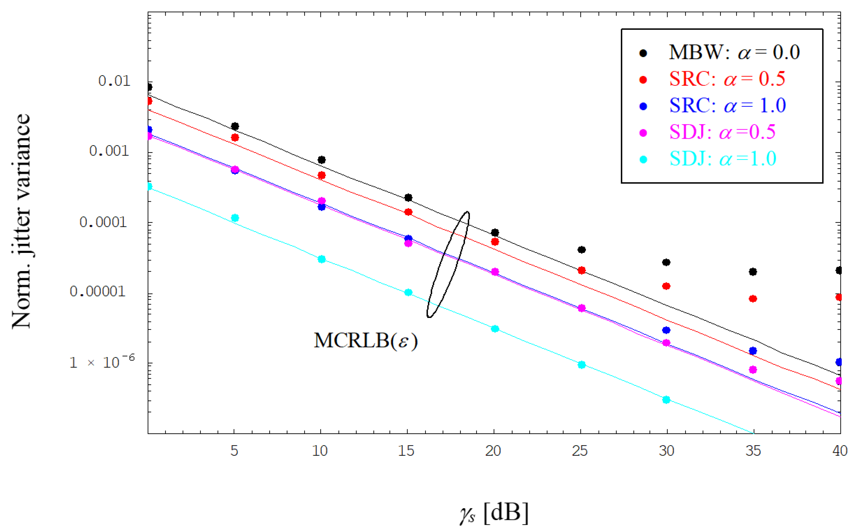
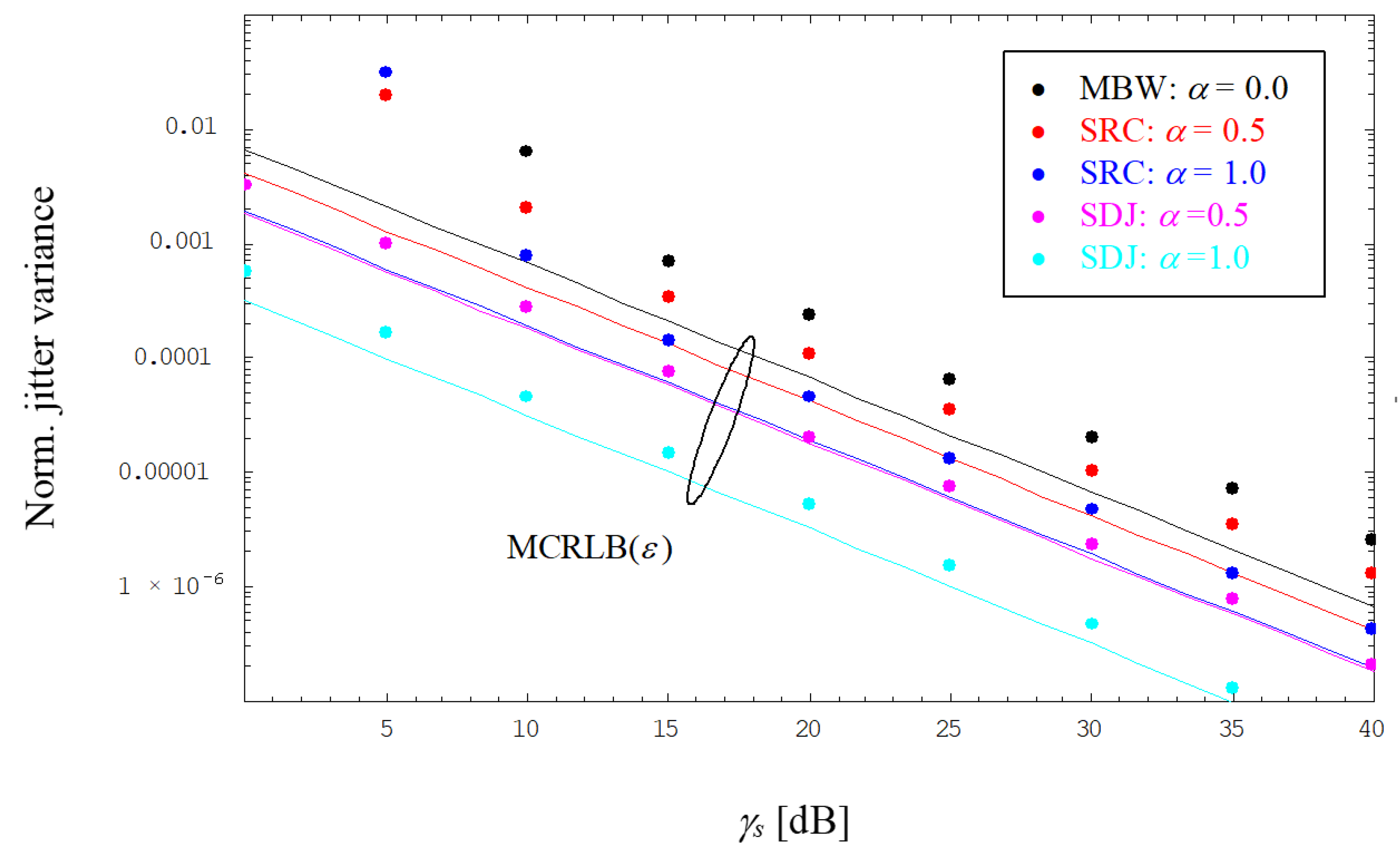
Figure 5 and
Figure 6 depict the evolution of the normalized jitter variance for timing estimates using an MF or FF receiver, respectively, and operating the link with SRC or SDJ shapes. By detailed inspection of
Figure 5, we observe that the MF solution is close to the MCRLB in the medium-to-low SNR range, whereas for larger SNRs, the jitter performance ends up in an error floor, which is obviously less severe for higher values of
α. This phenomenon is explained by the fact that the receiver MF violates the Nyquist property of the SRC/SDJ shape, producing this way an ISI effect that does not disappear, even if the AWGN component vanishes when
γs → ∞. In addition, it is to be noticed that SDJ pulses exhibit a better jitter performance than do SRC shapes; note that for
α = 0, both scenarios converge to the MBW case.
For comparison purposes, the FF results are shown in
Figure 6. We can see immediately that the FF variant exhibits no floor effect, simply because the receiver filter does not distort the orthogonality of the SRC/SDJ function. On the other hand, it is to be noticed that the jitter performance is only close to the MCRLB for higher values of
α and
γs > 10 dB; otherwise, the performance degrades compared to MF, mainly because significantly more noise passes the flat filter.
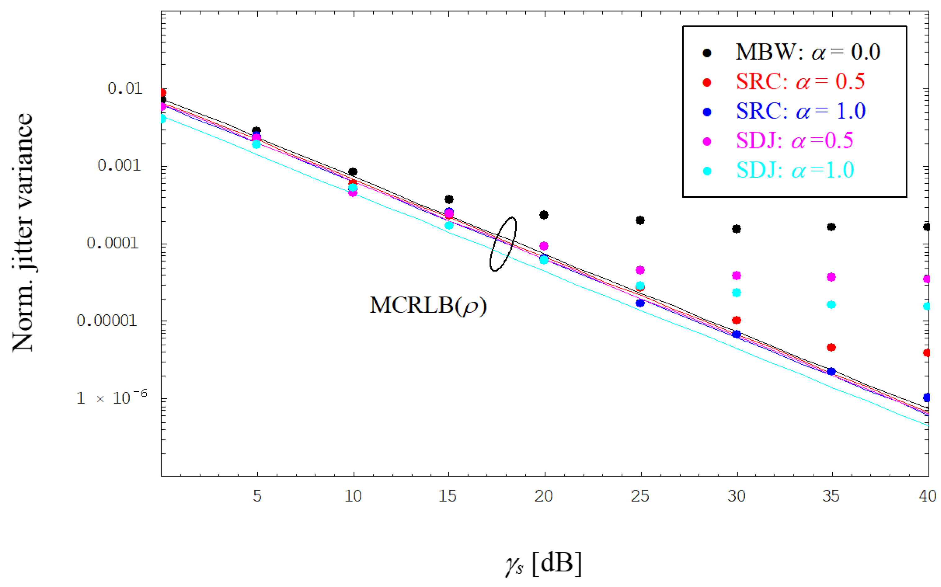
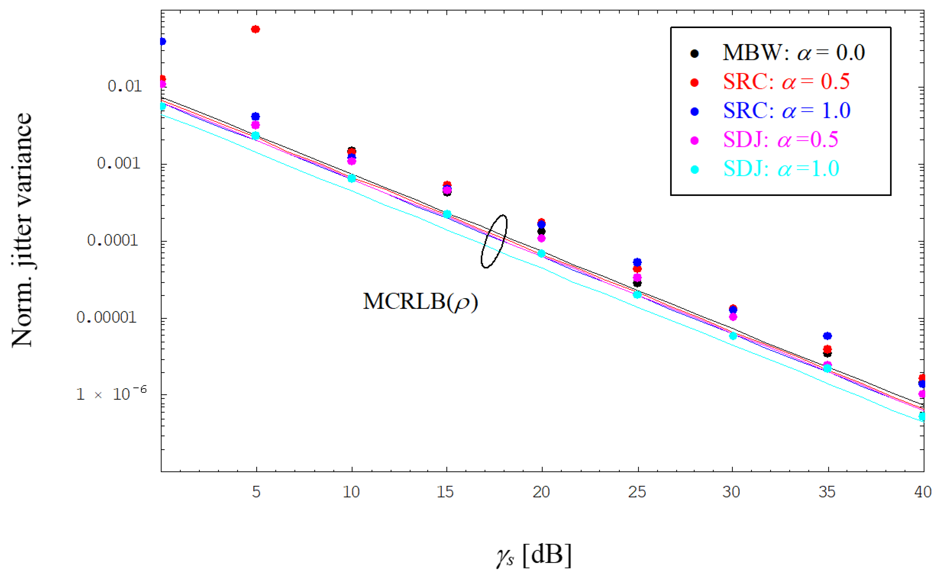
Additionally, as a function of the average electrical SNR,
Figure 7 and
Figure 8 show the evolution of the normalized jitter variance of amplitude estimates using MF and FF scenarios, respectively, again operating the link with SRC or SDJ shapes. In contrast to the recovery of the symbol timing, the MCRLB is more or less the same, irrespective of the chosen excess bandwidth. This is also confirmed in
Figure 7 by numerical results achieved in the lower SNR range, where they are close to the MCRLB. For larger SNRs, we observe an error floor caused by the violation of the Nyquist condition; again, this sort of degradation is less severe for increasing values of
α. Interestingly, given the same roll-off factor, the floor effect is more pronounced for SDJ than for SRC.
Not surprisingly, the jitter floor vanishes by application of the FF method, whose jitter performance is visualized in
Figure 8. Due to the larger amount of noise at the FF output, we face a higher jitter variance compared to results in
Figure 7 by taking the MCRLB as a benchmark; solely for smaller values of SNR and
α, the error performance worsens somewhat due to an increasing number of outliers caused by a failure of the estimator algorithm.
6. Conclusions
Assuming a pulse shaping embodied by SRC and SDJ functions, the estimation of symbol timing and signal amplitude has been studied in the context of a bandlimited optical intensity link. To this end, the modified Cramer–Rao lower bound was derived as the theoretical limit of the jitter variance exhibited by an estimator algorithm. Regarding the latter, it turned out that a maximum likelihood solution is suboptimal, because it involves a receiver matched filter violating the Nyquist criterion such that the jitter performance ends up in an error floor. It could be verified that this drawback might be circumvented by a flat filter structure, although the jitter variance increases somewhat in this case, because of a larger amount of noise passing the filter.
A subject for future research is the extension of the estimation problem to a non-data-aided situation [
21], i.e., data symbols need not be known to the receiver in the form of preambles or pilot sequences, increasing in this way the spectral efficiency of the optical link.
