Abstract
An existing riverine platform in Egypt, together with its pile group foundation, is analyzed under environmental loads using 3D FEM structural analysis software incorporating soil-pile interaction. The interaction between the transfer plate and the piles supporting the platform is investigated. Two connection conditions were studied assuming fixed or hinged connection between the piles and the reinforced concrete platform for the purpose of comparison of the structural behavior. The analysis showed that the fixed or hinged connection condition between the piles and the platform altered the values and distribution of displacements, normal force, bending moments, and shear forces along the length of each pile. The distribution of piles in the pile group affects the stress distribution on both the soil and platform. The piles were found to suffer from displacement failure rather than force failure. Moreover, the resulting bending stresses on the reinforced concrete plate in the case of a fixed connection between the piles and the platform were almost doubled and much higher than the allowable reinforced concrete stress and even exceeded the ultimate design strength and thus the environmental loads acting on a pile-supported riverine offshore platform may cause collapse if they are not properly considered in the structural analysis and design.
1. Introduction
The riverine platforms at the Nile River in Egypt are used for several purposes in the development of civilization utilities and projects. Urbanization in the countryside and the narrow valley increases the need for mega-projects across the Nile River, such as bridges and water projects that require deep foundations (such as caissons or piles) at the bottom of the river. Egyptian national projects of great importance have been constructed across the Nile River and among them the Sohag water plant. The Nile river water pump station in Sohag city (at the western project in the first Shush Street) was investigated to assess the safety of the structure under environmental and working loads. The riverine platform is subjected to dead, live, and environmental loads (wind, water waves, and water current loads). The upper reinforced concrete plate transmits these loads to the piles and the piles transmit the loads to the soil surrounding and beneath them.
Concerning pile structural behavior, Lysmer and Kuhlemeyer [1] concluded that the maximum deflection in the upper part of the pile decreases with pile depth, and an increase of pile size did not cause a significant impact on pile response. For the dynamic response, Tallavó et al. [2] studied the average frequency of a platform during the period May 1993 to July 1994 and found that it was 0.42 Hz with a standard deviation of 0.0042 Hz. Razavi et al. [3] concluded that the batter piles increase the lateral stiffness of pier and reduce displacement, and it is recommended to avoid the use of batter piles with plumb piles in a design. Chau et al. [4] tested a soil-pile-structure model on a shaking table for medium-graded river sand with a single-storey steel structure placed on a concrete pile cap, supported by four end-bearing concrete piles, and they found that the acceleration at the level of the pile cap increased by three times compared to the structure acceleration. Nonlinear pounding between piles and soils occurred, and as a result, cracking in piles occurred. Hussien et al. [5] studied the seismic response of end bearing piles supporting simple structures and their results showed that the inertial effect of the superstructure on the pile response is frequency dependent and the pile response at low frequencies is controlled basically by its bending rigidity rather than the kinematic effect of soil or inertial effect of structure. Abu Seif and El-Shater [6] concluded that Sohag Governorate, especially in the floodplain region, has encountered numerous specific construction problems because of Sohag’s unique sedimentation history and where loading is high, deep foundations are usually used to reduce settlement, or ground improvement is applied to a depth of up to 15 m. Mandal et al. [7] investigated the lateral load carrying capacity of short piles in layered soil and they concluded that the elastic properties of the pile-soil system are conceptually more relevant for analyzing the elastic range response and are hence used as fundamental parameters. Chore et al. [8] concluded that the increase in number of piles in a pile group decreases the displacement, the increase in the pile diameter reduces the displacement, parallel configuration of the pile group yields higher displacement than the series arrangement, the end bearing pile yields less displacement than the floating pile, and the SSI is found to increase the maximum negative and maximum positive bending moment on piles. Ravi Kumar Reddy and Gunneswara Rao [9] studied an experimental and numerical model of a building frame resting on pile groups embedded in cohesionless soil and the experimental results showed non-linear variation and considerable deviation from the linear FEA results, and for the frame under the eccentric concentrated load, larger lateral displacements generated rotations and lesser settlements at the column base of the far end from the load. Kaynia [10] studied the effect of flexible slabs on the dynamic and seismic responses of pile groups and concluded that the stiffness and damping of pile foundations increase with the thickness of the foundation slab, and the flexible slabs tend to reduce the large peaks of horizontal stiffness at the pile group. Asgarian et al. [11] studied an experimental and numerical simulation of a jacket type offshore platform subjected to an earthquake in order to investigate the effect of soil-pile-structure interaction and concluded that soil-pile-structure interaction decreases the natural frequency and increases the equivalent modal damping of the structure. Cheng and Liu [12] proposed an efficient and practical algorithm for the reliability analysis of steel cable-stayed bridges and concluded that the effect of the soil-pile interaction is not significant in evaluating the reliability, but the modulus of subgrade reaction is the most important soil-pile interaction-related parameter. Hamilton [13] concluded that for a pile, the least amount of deformation occurred in the middle range of saturation of soil due to the rapid loading rates which occur during earthquakes and the saturated nature of the foundation. Dode et al. [14] concluded that the increase in the displacement is observed to be in the range of 38% to 75% when the effect of SSI is taken into account for groups with two and three piles; however, increasing the number of piles can result in a decrease of the displacement. Mehndiratta et al. [15] concluded that increasing the piles’ diameter, decreases the response of the pile groups and vice versa. As the length of the pile increases, the maximum deflection first decreases and then becomes constant. Sand Poisson’s ratio and density do not have any considerable effect on pile head displacement. Maximum bending moment decreases as the elastic modulus of soil increases. Abdel-Mohti and Khodair [16] studied the pile-soil interaction in a soft soil under axial and lateral loading using finite difference and finite element software which defined soil as isolated springs and found that the seismic soil-pile-structure interaction increases lateral displacement, which shifts the performance level of the structure from life safe to near collapse or collapse levels. Kaynia and Andersen [17] and Kaynia et al. [18] represented the soil under the platform as springs with stiffness tuning with the concrete stiffness values. Kim et al. [19] studied a laterally loaded mono-pile type offshore wind turbine supported by a series of discrete springs, each having its own nonlinear load-displacement characteristics, and concluded that the internal friction angle of seabed sandy soil is the most dominant design factor. Yi et al. [20] studied wind turbine offshore models supported by mono-pile, and found that the natural frequency was more significantly affected by the equivalent load amplitude, and the jacket-supported offshore wind turbine is more robust in terms of the consistency of the natural frequency under different equivalent load amplitudes and uncertain soil conditions, at water depths between 20 and 30 m. Durante et al. [21] concluded that the complex seismic pile-soil interaction phenomenon can be efficiently investigated by testing models on a shaking table. Chatterjee et al. [22] studied the seismic analysis of a laterally loaded pile applying a pseudo-static methodology and concluded that if the soil is saturated, the bending moment at the pile top is amplified by around 4 and 7.8 times (for two specific seismic motions respectively), and that with a reduction in the l/d ratio of the pile, the normalized moment at the pile head is increased while the normalized displacement is reduced. Ukritchon et al. [23] concluded that in a pile group, the maximum effect happens at the corner piles and it decreases as the location of the pile gets closer to the center but increases again below the applied vertical load. Additional discussion on the effects and modeling of SSI can be found in the book by Elnashai and Di Sarno [24], where a detailed description of the pros and cons of the methods for assessing SSI is also included.
In this paper, the structural analysis of an existing riverine platform (with dimensions 26 m × 17 m) in Sohag city was performed using the finite element-based computer software SAP2000 v.17 (Computers and Structures, Inc., Walnut Creek, CA, USA) [25] and the effects of the environmental loads affecting such a platform were studied, especially the impact of these loads on the pile groups that are supporting this platform taking into consideration the soil-pile-structure interaction. Two connection conditions were studied assuming a fixed or hinged connection between the piles and the reinforced concrete platform for the purpose of comparison.
2. Model Description
The Nile river water pump station in Sohag city (at the western project in the first Shush Street) consists of a pedestrian bridge with a length of 90 m mounted on 62 piles and a platform with dimensions of 26 m × 17 m as shown in Figure 1. The transfer reinforced concrete plate is 800 mm thick (with upper and lower reinforcement meshes 8φ18/m’ in both directions, rebar chairs φ22/m’ in both directions to hold in position the upper mesh and reinforcement cover 50 mm at top and bottom) and is mounted on 108 piles. Transfer plate structures have the ability to redistribute the loads from the superstructure above to the pile group below, to provide the safe transmission of loads to the pile group and to the soil without the failure of soil or structural elements. The platform is constructed at a distance of 100 m away from the river bank. Each pile has a circular section of 550 mm diameters with steel pipe casing of 20 mm thick. The pile length is 25 m, out of which 14 m are embedded in the river bed. Figure 2 shows the dimensions and the arrangement of piles in the platform, where the distances between piles are not equal. Table 1 represents the geometrical and material properties of the structural elements of the platform and piles. (These values of Young’s modulus of elasticity and Poisson’s ratio for concrete are also used for piles by Chore and Ingle [26]).
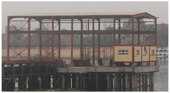
Figure 1.
Platform view.
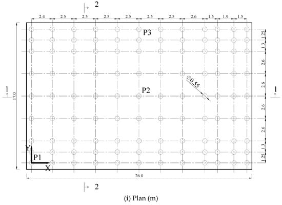
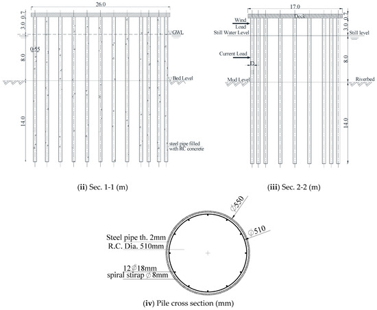
Figure 2.
The platform plan and sections.

Table 1.
Geometrical and material properties for the elements of the platform and piles.
The vertical loads acting on the platform are as follows: a steel frame having a total weight of 300 kN, six pumps causing a total force of 600 kN, two generators with a weight of 60 kN, electricity panel causing a load of 5 kN, and additionally distributed live loads of 10 kN/m2 acting on the area of the platform. The effects of the steel frame and the equipment loads on deck were considered and modeled as distributed load on the platform. The environmental loads including the wind load effect and the surrounding water wave and current load effects on the platform and piles are presented in Section 2.3. Thus, the platform is subjected to the following loads: (1) Own weight of the steel frame structure, the RC plate, and the equipment loads; (2) Moving loads of the forklift and live load on the RC plate; and (3) Environmental loads consisting of the wind, wave, and current forces.
2.1. Computer Modeling of Platform
A three-dimensional structural model was constructed by the finite element method and materially nonlinear static analysis was performed for the platform and the supporting piles. Two supporting conditions were considered assuming a fixed and hinged connection between piles and the reinforced concrete platform for the purpose of comparison. The SAP2000 v.17 software [25] was used to obtain the responses of the transfer plate and pile group, where the finite element model is shown in Figure 3. The thick reinforced concrete plate of the platform was modeled using four-noded thick shell elements and the additional loads and masses on the top of the platform structure were assumed as uniformly distributed loads (including steel frames, pumps, generators, electricity panels, and live load). The piles were modeled utilizing frame elements. The soil (until 2 m depth) was modeled by spring-gap elements with stiffness k and gap distance δ used between each pile and the soil at a depth of 1 m under the soil surface (both in x and y directions), to account for the gap that may occur between the pile and soil due to the lateral load actions. For the remaining depth (under the 2 m), the soil was modeled by soil springs (without gap) in three-dimensions until the bearing level (i.e., the end) of each pile. The soil around the pile group was considered to be formed of three layers with different properties as described in Section 2.5. The results of the two models with fixed and hinged connections between the piles and the platform were compared.
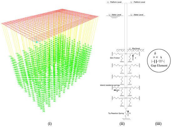
Figure 3.
(i) The 3D finite element model used in SAP2000 v.17, (ii) Illustration of soil springs, and (iii) Spring-Gap element (at 1 m under bed level).
2.2. Natural Vibration Analysis
Eigenvector analysis determines the undamped free-vibration mode shapes and natural frequencies of the system. These natural modes provide an excellent insight into the behavior of the structure and they can also be used as the basis for response-spectrum or time-history analyses. Eigenvector analysis involves the solution of the generalized eigenvalue problem:
where K is the stiffness matrix, M is the diagonal mass matrix, ω2 is the diagonal matrix of eigenvalues, and φ is the matrix of corresponding eigenvectors (mode shapes).
(K − ω2M)φ = 0
For natural vibration analyses, a total seismic mass including self-weight DL plus 25% of LL (1.0 DL + 0.25 LL) is considered (ACI 318 [27]; ECP-201 [28]). The natural periods and vibration mode shapes are computed by eigenvalue analysis. The values of natural periods are shown in Table 2 for up to the six modes of vibration and the first three vibration modes are shown in Figure 4.

Table 2.
First six eigenvalues and natural periods of the model assuming a fixed and hinged connection between the piles and the reinforced concrete plate of the platform.
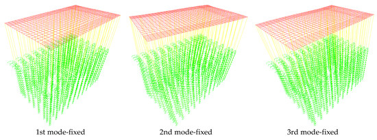
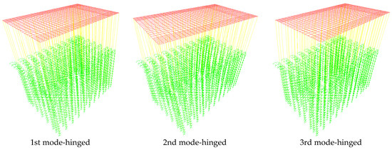
Figure 4.
First three mode shapes of the model assuming a fixed and hinged connection between the piles and the reinforced concrete plate of the platform.
2.3. Environmental Loads
The environmental loads include water current loads, water wave loads, and wind loads that were considered as follows:
2.3.1. Current Force
The drag force is given by Equation (2) (API [29]; Chandrasekaran [30]):
where, FD is the drag force (kN), Cd is the drag coefficient, ρ is the water density (t/m3), A is the cross section (m2), and U is the current velocity ranging from 0.1 to 2.3 m/s (Sutcliffe and Parks [31]). This force acts on the part of piles between the water and bed level.
2.3.2. Wave Force
The total force is calculated by using Morison’s equation, which decomposes the total force into an inertia component and a drag component (API [29]; Chandrasekaran [30]):
where F is the total force, Cm is the inertia coefficient, u is the current velocity, is the current acceleration, and V is the object volume. This force acts on piles at the water level position.
2.3.3. Wind Force
The wind force is assumed as recommended by Egyptian Code for the calculation of loads and forces ECP-201 [28] as follows:
where F is the wind force in kN, Cs is the shape structure factor, Ap is the cross section (m2), and U10 is the wind velocity (Km/h). This force acts on the part of piles over the water level and an equivalent wind force from the steel frame on the platform.
2.4. Design of Piles for Skin Friction and Tip Resistance
In this study, the piles supporting the platform are considered as combined skin friction and bearing pile type (Mosher and Dawkins [32]; NAVFAC [33]). The full ultimate downward capacity of the pile for both types of side resistance (skin friction) and tip resistance (end-bearing) piles according to the NAVFAC [33] is obtained as follows:
where QU is the ultimate downward capacity, Qtip is the ultimate tip resistance (end-bearing capacity), and Qside is the ultimate side resistance (skin friction capacity).
QU = Qtip + Qside
2.5. Soil Layers of River Bed
Characterization of the soil under the bed level of the Nile River and a description of each soil layer can be found, e.g., in Warner et al. [34].
From bed level until 2 m under bed level (i.e., bed: −2.00), the soil is the same as that of Layer (1) in Table 3 and this depth is represented as two spring-gap elements (at 1 m under bed level, one in x-direction and one in y-direction) between each pile and the soil to account for the gap that may occur between each pile and the soil due to the lateral load actions, where the gap distance equals zero and the stiffness of the spring equals Kx = Ky of Layer (1) in Table 3.

Table 3.
Properties of the three soil layers.
Additionally, from 2 m to 14 m under the bed level, the three layers of soil (which the piles of the platform pass through) were modeled as soil springs in three-dimensions arranged all over the length of the piles until the end of the piles. Table 3 represents the herein used three river bed soil layers and summarizes their properties (Mandal et al. [7]) and the calculated stiffness in three-dimensions: Kx, Ky, and Kz (Newmark and Rosenblueth [35]; Mosher and Dawkins [32]; NAVFAC [33]).
3. Results and Discussion
The riverine platform constructed in the Nile River was analyzed under different loading conditions to check its ability to withstand the applied loads and environmental effects that it may be exposed to. The three main environmental loads were taken into consideration. The wind loads which were considered to affect the steel frame and the part of the piles over water level, the wave forces which were assumed to affect the piles at the water level, and the current forces which were assumed to affect all piles from the water level until bed level.
The SAP2000 v.17 software [25] was used to analyze the platform and piles. Materially nonlinear static analyses were performed for the platform and the supporting piles. The connection between pile heads and the reinforced concrete platform was assumed to be fixed in one case and to be hinged in another case for the purpose of comparison of the structural behavior.
The pile response was obtained in the form of displacement in the x and y horizontal directions, normal force (Nf), shear forces in the x and y directions (Qx and Qy), and the bending moments Mx and My. Three piles at different locations were selected for the response investigation as marked by P1 at position x = 0 m and y = 0 m, P2 at position x = 12.4 m and y = 7.75 m, and P3 at position x = 12.4 m and y = 15.5 m, as shown in Figure 2. Table 4 illustrates the pile response symbols and their descriptions that will be used in the following Figures and discussion.

Table 4.
Symbol definitions.
Figure 5 shows the displacements in x and y directions for the selected three piles P1, P2, and P3 (located at different distances) assuming a hinged connection between each pile and the reinforced concrete platform plate. Top displacements in the x direction for piles at different distances resulted in large differences in their values; however, at the river bed level (at depth of −12 m), the values of displacements were relatively closer, as depicted in Figure 5a. Figure 5b illustrates the displacements in the y direction for the same selected piles. It is obvious that the values of y displacements are very close and tend to be almost identical. It is also realized that the displacement at a depth of −12 m (river bed level) in the y direction is about 40% larger than the displacements in the x direction. This behavior can be explained by the fact that the reinforced concrete plate acted as a rigid diaphragm in its short direction (width of 17 m) so all piles suffered almost the same top displacement in the y direction. However, the longer side of the reinforced concrete plate with a length of 26 m in the x direction (rectangularity ratio = 1.53) reduced its rigidity, leading to the resulting large differences in the pile top displacements.
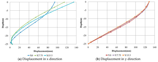
Figure 5.
Displacements of selected different distance piles assuming a hinged connection between the piles and the reinforced concrete plate of the platform.
Figure 6 illustrates the displacements in x and y directions for the selected three piles (P1, P2, and P3) assuming a fixed connection with the reinforced concrete plate. The top displacements of the piles at different distances are greatly reduced compared with the hinged connection case and kept constant values for the upper nearly 2 m length due to the fixation effect, as shown in Figure 6a. On the other hand, displacement in the y direction showed similar values and behavior as the case of a hinged connection, as can be realized from the comparison of Figure 5b and Figure 6b. Therefore, it can be stated that the fixed connection between the piles and the reinforced concrete plate increased the overall stiffness and rigidity of the platform structure in the long direction without a remarkable effect in the short direction.
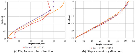
Figure 6.
Displacements of selected different distance piles assuming a fixed connection between the piles and the reinforced concrete plate of the platform.
Figure 7a,b show the normal forces for the selected piles (at different distances) considering a fixed and hinged connection with the platform, respectively. For the case of the pile group connected to the platform, the normal forces in the pile at the edge of the platform (P1) are generally lower than the corresponding values for the piles P2 and P3. The value of the normal forces remained constant for all piles up to the river bed level (at −12 m depth), then sharply decreased with the depth, especially for piles P2 and P3, as shown in Figure 7a,b for both fixed and hinged connection conditions, respectively. For all piles, the hinged connection condition resulted in higher values for the normal forces than the fixed condition.
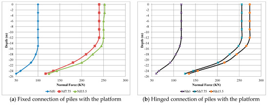
Figure 7.
Normal forces acting on the selected piles P1, P2, and P3 with a fixed and hinged pile-platform connection.
Figure 8 shows the bending moments in both x and y directions along the selected piles P1, P2, and P3 assuming fixed and hinged connections of piles to the platform. The bending moments in the x direction along piles P1, P2, and P3 for the fixed connection case are depicted in Figure 8a. The direction of bending moment changed at the bed level for the inner piles P2 and P3 with the maximum value at the pile top. For the edge pile P1, there were two inflection points, one of them close to the surface and the second one below the bed level. The maximum value occurred in the upper part at a depth of about −8 m. For the hinged connection case, there was no moment at the pile top as expected. The maximum moment occurred below the bed level for piles P2 and P3, as shown in Figure 8b. However, the moment distribution along the edge pile P1 showed an intermediate inflection point at the bed level and the maximum value was at a depth of −6 m, approximately in the upper part. Comparing the maximum values of both connection cases revealed that the fixed connection condition resulted in higher bending moment for inner piles P2 and P3, while the edge pile P1 suffered almost the same maximum bending moment in both cases. The bending moments in the y direction for piles with a fixed connection are given in Figure 8c. The same distribution trend along the pile length as x direction moments could be observed here with opposite sign conventions. However, the moments at the pile top possessed a larger value for piles P2 and P3. It can be realized that the moment in the y direction is about 50% higher than the moment in the x-direction for the same piles. On the other side, the case of the hinged connection resulted in y-direction moment with a similar trend and almost the same values for the observed bending moments in the x direction, as can be observed form the comparison between Figure 8d and Figure 8b.
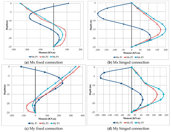
Figure 8.
Bending moments along the selected piles P1, P2, and P3 assuming fixed and hinged pile-platform connections.
Figure 9 shows shear forces acting on the selected three piles P1, P2, and P3 calculated from the top level to the bearing level of piles in both x and y directions assuming fixed and hinged connection conditions. Shear forces in the x direction acting on the inner piles P2 and P3 were approximately equal in values and have the same distribution trend along the pile length in both directions for both cases of fixed and hinged connections, as shown in Figure 9a,b. The shear forces showed almost constant positive values from the top level up to the bed level, then started to decrease in value to be zero and continued to possess negative values and again reached a zero value at the pile tip. This behavior is owed to the interaction with the surrounding soil that was presented by soil springs. The shear forces that resulted in the case of a fixed condition showed higher values than the case of a hinged condition in the upper part of the pile length, meanwhile, the shear forces possessed higher values in the lower 10 m in the case of hinged condition. On the other hand, the shear forces in the x direction acting on the outer edge pile P1 showed a different distribution trend along the pile length, where the values altered between negative values at the upper third, positive values in the middle third, and negative values in the lower third. The resulting value at the top was larger in the case of the fixed condition, while the case of the hinged condition resulted in a higher shear force in the middle third of the pile. The resulting shear forces in the y direction are depicted in Figure 9c,d, for the fixed and hinged conditions, respectively. A similar trend to the shear forces in the x direction was also observed in the distribution and values of the shear forces in the y direction; however, the hinged condition resulted in almost an identical response to the fixed condition case. This behavior is expected as the displacement distributions in the y direction were identical in both cases, as previously shown in Figure 5b and Figure 6b.
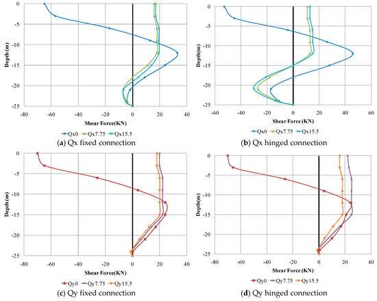
Figure 9.
Shear forces acting on the selected piles P1, P2, and P3 assuming fixed and hinged pile-platform connections.
Figure 10 represents the stress contours in the reinforced concrete plate in the x and y directions for both fixed and hinged connection cases. The resulting stresses in both directions were much higher in the case of fixed conditions. The ratio of the stress values resulted from the fixed case to the similar stress values in the hinged case reached 2 in some places. The stress values exceeded 43 MPa, which is much higher than the allowable stress of the reinforced concrete plate that has an ultimate compressive strength of 40 MPa.
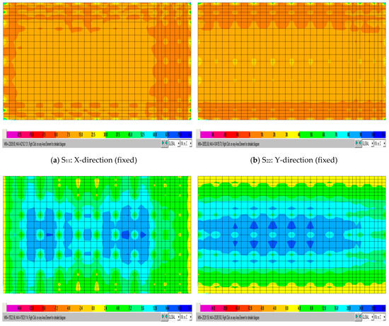
Figure 10.
Stress contours in the RC plate assuming a fixed and hinged connection with piles.
4. Conclusions
A structural analysis was performed for an existing pile-supported riverine platform in order to study its structural response under environmental and static loads incorporating soil-pile interaction. The environmental loads acting on the platform were wind, water waves, and water current loads. The pile response in terms of displacements, normal forces, bending moments, and shear forces were obtained assuming a fixed or hinged connection between the pile and the reinforced concrete platform. The behavior of a structure is changed with the soil flexibility and pile-soil-structure interaction was considered in the analysis for a real prediction of the overall structure response.
The analysis showed that the distribution of piles in the pile group strongly affects the distribution and values of the straining actions on piles. The position of each pile with respect to the platform edge showed a considerable effect.
The resulting top displacements of the piles in the long direction of the platform assuming a fixed connection were greatly reduced compared with a hinged connection, while the connection condition did not affect the displacements in the short direction of the platform. Therefore, it can be stated that the fixed connection between the piles and the reinforced concrete plate increased the overall stiffness and rigidity of the platform structure in the long direction without a remarkable effect in the short direction.
The normal forces acting on piles at the edge of the platform were generally lower than the corresponding values for the inner piles. For all piles, the hinged connection condition resulted in higher values for the normal forces than the fixed condition.
The resulting bending moments were highly dependent in values and distribution on the pile position and the connection condition (fixed or hinged) with the platform.
For the inner piles, the shear forces in the long direction of the platform showed almost constant positive values from the top level down to the bed level, then started to decrease in value to become zero and afterwards to possess negative values and again to reach a zero value at the pile tip due to the interaction with the surrounding soil. The shear forces in the case of a fixed condition showed higher values than the case of a hinged condition in the upper part of the pile length, meanwhile, the shear forces possessed higher values in the lower 10 m in the case of hinged condition. On the other hand, the shear forces in the x direction acting on the outer edge pile showed a different distribution trend along the pile length, where the values altered between negative values at the upper third, positive values in the middle third, and negative values in the lower third.
The resulting bending stresses in both the x and y direction were almost doubled in the case of fixed conditions. The resulting stress values exceeded the allowable stress of the reinforced concrete plate. Thus, the environmental and static loads acting on the platform may cause collapse if they are not properly considered in the structural analysis and design.
Author Contributions
D.-P.N.K. and A.A.F. both contributed to the organizing of the research and the writing of this paper.
Conflicts of Interest
The authors declare no conflict of interest.
References
- Lysmer, J.; Kuhlemeyer, R.L. Finite Dynamic Model for Infinite Media. J. Eng. Mech. Div. (ASCE) 1969, 95, 859–878. [Google Scholar]
- Tallavó, F.; Martinez, M.E.; Ewins, D.J. Experimental evaluation of vibrations in an operating offshore platform. In Proceedings of the 13th International Modal Analysis Conference (IMAC XIII), Nashville, TN, USA, 13–16 February 1995; Society for Experimental Mechanics Inc.: Bethel, CT, USA, 1995; pp. 1847–1852. [Google Scholar]
- Razavi, S.A.; Fakher, A.; Mirghaderi, S.R. An Insight into the Bad Reputation of Batter Piles in Seismic Performance of Wharves. In Proceedings of the 4th International Conference on Earthquake Geotechnical Engineering, Thessaloniki, Greece, 25–28 June 2007; Pitilakis, K.D., Ed.; Springer: Dordrecht, Germany, 2007; pp. 1–10. ISBN 978-1-4020-5893-6. Available online: http://extras.springer.com/2007/978-1-4020-5893-6/paperpdf/1423_raz.pdf (accessed on 2 January 2017).
- Chau, K.T.; Shen, C.Y.; Guo, X. Nonlinear seismic soil–pile–structure interactions: Shaking table tests and FEM analyses. Soil Dyn. Earthq. Eng. 2009, 29, 300–310. [Google Scholar] [CrossRef]
- Hussien, M.N.; Tobita, T.; Iai, S. Experimental and FE analysis of seismic soil-pile-superstructure interaction in sand. Ann. Disaster Prev. Res. Inst. B 2010, 53, 299–306. Available online: http://www.dpri.kyoto-u.ac.jp/nenpo/no53/ronbunB/a53b0p34.pdf (accessed on 2 January 2017).
- Abu Seif, E.-S.S.; El-Shater, A.A. Engineering aspects and associated problems of flood plain deposits in Sohag Governorate, Upper Egypt. J. Am. Sci. 2010, 6, 1614–1623. [Google Scholar] [CrossRef]
- Mandal, B.; Roy, R.; Dutta, S.C. Lateral capacity of piles in layered soil: A simple approach. Struct. Eng. Mech. 2012, 44, 571–584. [Google Scholar] [CrossRef]
- Chore, H.S.; Ingle, R.K.; Sawant, V.A. Building frame–pile foundation–soil interaction analysis: A parametric study. Interact. Multiscale Mech. 2010, 3, 55–79. [Google Scholar] [CrossRef]
- Ravi Kumar Reddy, C.; Gunneswara Rao, T.D. Experimental study of a modeled building frame supported by pile groups embedded in cohesionless soil. Interact. Multiscale Mech. 2011, 4, 321–336. [Google Scholar] [CrossRef]
- Kaynia, A.M. Dynamic response of pile foundations with flexible slabs. Earthq. Struct. 2012, 3, 495–506. [Google Scholar] [CrossRef]
- Asgarian, B.; Shokrgozar, H.R.; Shahcheraghi, D.; Ghasemzadeh, H. Effect of soil pile structure interaction on dynamic characteristics of jacket type offshore platforms. Coupled Syst. Mech. 2012, 1, 381–395. [Google Scholar] [CrossRef]
- Cheng, J.; Liu, X.-I. Reliability analysis of steel cable-stayed bridges including soil-pile interaction. Steel Compos. Struct. 2012, 13, 109–122. [Google Scholar] [CrossRef]
- Hamilton, M. Pile-Soil Interaction in Unsaturated Soil Conditions; Senior Honors Thesis in Partial Fulfillment of the Requirements for Honors in Civil Engineering; University of New Hampshire: Durham, NH, USA, 2014; Available online: http://scholars.unh.edu/cgi/viewcontent.cgi?article=1181&context=honors (accessed on 2 January 2017).
- Dode, P.A.; Chore, H.S.; Agrawal, D.K. Interaction analysis of a building frame supported on pile groups. Coupled Syst. Mech. 2014, 3, 305–318. [Google Scholar] [CrossRef]
- Mehndiratta, S.; Sawant, V.A.; Samadhiya, N.K. Nonlinear dynamic analysis of laterally loaded pile. Struct. Eng. Mech. 2014, 49, 479–489. [Google Scholar] [CrossRef]
- Abdel-Mohti, A.; Khodair, Y. Analytical investigation of pile–soil interaction in sand under axial and lateral loads. Int. J. Adv. Struct. Eng. 2014, 6, 1–16. [Google Scholar] [CrossRef]
- Kaynia, A.M.; Andersen, K.H. Development of nonlinear foundation springs for dynamic analysis of platforms. In Proceedings of the Frontiers in Offshore Geotechnics III–3rd International Symposium on Frontiers in Offshore Geotechnics (ISFOG 2015), Oslo, Norway, 10–12 June 2015; Meyer, V., Ed.; CRCPress/Balkema–Taylor & Francis Group: Leiden, The Netherlands, 2015; Volume 1, pp. 1067–1072. [Google Scholar]
- Kaynia, A.M.; Norén-Cosgriff, K.; Andersen, K.H.; Tuen, K.A. Nonlinear foundation spring and calibration using measured dynamic response of structure. In Proceedings of the 34th International Conference on Ocean, Offshore and Arctic Engineering, OMAE2015, St. John’s, NL, Canada, 31 May–5 June 2015; ASME: New York, NY, USA, 2015; Volume 1. [Google Scholar] [CrossRef]
- Kim, S.B.; Yoon, G.L.; Yi, J.H.; Lee, J.H. Reliability analysis of laterally loaded piles for an offshore wind turbine support structure using response surface methodology. Wind Struct. 2015, 21, 597–607. [Google Scholar] [CrossRef]
- Yi, J.-H.; Kim, S.-B.; Yoon, G.-L.; Andersen, L.V. Natural frequency of bottom-fixed offshore wind turbines considering pile-soil-interaction with material uncertainties and scouring depth. Wind Struct. 2015, 21, 625–639. [Google Scholar] [CrossRef]
- Durante, M.G.; Di Sarno, L.; Mylonakis, G.; Taylor, C.A.; Simonelli, A.L. Soil–pile–structure interaction: Experimental outcomes from shaking table tests. Earthq. Eng. Struct. Dyn. 2015, 45, 1041–1061. [Google Scholar] [CrossRef]
- Chatterjee, K.; Choudhury, D.; Poulos, H.G. Seismic analysis of laterally loaded pile under influence of vertical loading using finite element method. Comput. Geotech. 2015, 67, 172–186. [Google Scholar] [CrossRef]
- Ukritchon, B.; Faustino, J.C.; Keawsawasvong, S. Numerical investigations of pile load distribution in pile group foundation subjected to vertical load and large moment. Geomech. Eng. 2016, 10, 577–598. [Google Scholar] [CrossRef]
- Elnashai, A.S.; Di Sarno, L. Fundamentals of Earthquake Engineering: From Source to Fragility, 2nd ed.; John Wiley & Sons, Ltd.: Chichester, UK, 2015; ISBN 978-1118678923. [Google Scholar]
- SAP2000® Version 17. Integrated Software for Structural Analysis and Design, Computers and Structures, Inc.: Walnut Creek, CA, USA; New York, NY, USA, 2015.
- Chore, H.S.; Ingle, R.K. Interaction Analysis of Building Frame Supported on Pile Group. Indian Geotech. J. 2008, 38, 483–501. [Google Scholar]
- American Concrete Institute (ACI). Building Code Requirements for Structural Concrete (ACI318-08) and Commentary (ACI318R-08); ACI: Farmington Hills, MI, USA, 2008; ISBN 978-0-87031-264-9. [Google Scholar]
- Egyptian Code of Practice for loading (ECP-201). Egyptian Code for Calculating Loads and Forces in Structural Work and Masonry; (ECP-201); Housing and Building National Research Center, Ministry of Housing, Utilities and Urban Planning: Cairo, Egypt, 2008.
- American Petroleum Institute (API). API Recommended Practice 2A-WSD (RP 2A-WSD), Recommended Practice for Planning, Designing and Constructing Fixed Offshore Platforms–Working Stress Design, 21st ed.; American Petroleum Institute (API): Washington, DC, USA, 2000. [Google Scholar]
- Chandrasekaran, S. Dynamic Analysis and Design of Offshore Structures, 1st ed.; Springer India: New Delhi, India, 2015; ISBN 978-81-322-2277-4 (eBook); 978-81-322-2276-7 (Hardcover); 978-81-322-3433-3 (Softcover). [Google Scholar] [CrossRef]
- Sutcliffe, J.V.; Parks, Y.P. The Hydrology of the Nile; Institute of Hydrology, International Association of Hydrological Sciences (IAHS) Special Publication No. 5; IAHS Press: Wallingford, UK, 1999; Available online: www.hydrosciences.fr/sierem/produits/biblio/hydrology%20of%20the%20Nile.pdf (accessed on 2 January 2017).
- Mosher, R.L.; Dawkins, W.P. Theoretical Manual for Pile Foundations, Report ERDC/ITL TR-00-5. U.S. Army Corps of Engineers, Engineer Research and Development Center: Washington, DC, USA, 2000. Available online: https://erdc-library.erdc.dren.mil/xmlui/bitstream/handle/11681/10873/9451.pdf?sequence=1&isAllowed=y (accessed on 2 January 2017).
- Naval Facilities Engineering Command (NAVFAC). Foundations and Earth Structures–Naval Facilities Engineering Command Design Manual 7.02 (NAVFAC DM 7.02); Naval Facilities Engineering Command (NAVFAC): Alexandria, VA, USA, 1986; Available online: http://web.mst.edu/~rogersda/umrcourses/ge441/dm7_02.pdf (accessed on 2 January 2017).
- Warner, J.W.; Gates, T.K.; Fahim, W.; Ibrahim, M.; Awad, M.; Ley, T.W. Hydraulic Conductivity and Vertical Leakage in the Clay Silt Layer of the Nile Alluvium in Egypt; Technical Report No. 60; Egypt Water Use and Management Project, Water Distribution Research Institute, Water Research Center, Ministry of Irrigation, Government of Egypt: Cairo, Egypt, 1984. Available online: http://pdf.usaid.gov/pdf_docs/PNAAR143.pdf (accessed on 2 January 2017).
- Newmark, N.M.; Rosenblueth, E. Fundamentals of Earthquake Engineering; Prentice-Hall: Englewood Cliffs, NJ, USA, 1971; ISBN 013336206X. [Google Scholar]
© 2018 by the authors. Licensee MDPI, Basel, Switzerland. This article is an open access article distributed under the terms and conditions of the Creative Commons Attribution (CC BY) license (http://creativecommons.org/licenses/by/4.0/).