Article

Numerical Study and Model Validation of Low-Pressure Hydrogen–Air Combustion in a Closed Vessel

1
Kharkiv Aviation Institute, National Aerospace University, Vadim Manka, str. 17, 61070 Kharkiv, Ukraine
2
Institute of Heat Engineering, Faculty of Power and Aeronautical Engineering, Warsaw University of Technology, Nowowiejska 21/25, 00-665 Warsaw, Poland
*
Author to whom correspondence should be addressed.
Computation 2025, 13(2), 54; https://doi.org/10.3390/computation13020054
Submission received: 5 January 2025 / Revised: 31 January 2025 / Accepted: 11 February 2025 / Published: 15 February 2025

Abstract

:
This study investigates the combustion behavior of hydrogen–air mixtures in a closed chamber at reduced initial pressure, focusing on applications in thermal energy methods (TEMs) for plastic processing. The primary goal was to develop and validate a numerical model capable of accurately predicting pressure and temperature profiles over time. By employing ANSYS Fluent 2024 R2 and the GRI-Mech 3.0 mechanism, a detailed combustion model was constructed and validated against experimental data, adhering to the standards outlined in EN 15967: 2011. Subsequent simulations under low-pressure conditions revealed consistent flame front propagation and turbulent flow patterns, crucial factors for achieving stable temperature distributions and optimal part placement. This validated model provides a valuable tool for predicting combustion effects, enhancing safety, and optimizing the performance of hydrogen-fueled TEM processes. By leveraging hydrogen as a clean and sustainable energy source, this research contributes to a more environmentally friendly approach to plastic processing. Future studies will delve into the combustion of hydrogen–air mixtures in the presence of plastic parts to further refine the efficiency and effectiveness of TEM processes.

1. Introduction

Current research on the combustion of fuel mixtures, including hydrogen, is primarily focused on thermal power engineering [1,2,3,4,5] and engine technology [6,7,8,9]. These studies typically aim to optimize the operational modes of specific equipment. With the advent of initiatives such as the New Industrial Strategy, the Climate and Energy Policy Framework, and the SRRI Roadmap (2021), energy sources must adhere to environmentally friendly standards. Consequently, significant attention has been directed toward the production, storage, and use of hydrogen as a replacement for fossil fuel-based energy sources. This includes research on thermal and biological processes, water splitting, and hydrogen purification [10]. An essential area of study within this framework involves the development of efficient, eco-friendly combustion systems. Simulation of fuel mixture combustion and creating reliable predictive models are critical tools in this regard [11]. Transitioning to carbon-free processing technologies not only aligns with climate-neutral industrial goals but also enhances safety in industrial processes [12,13,14]. While the combustion of fuel mixtures remains less widespread, it is particularly relevant for industrial material processing technologies, such as thermal energy methods (TEMs) [15,16]. These methods have been applied using low-pressure hydrogen–oxygen mixtures for tasks like deburring, defogging, and partial surface polishing of thermoplastics such as acrylic, polyurethane, and polyethylene [17,18].
To implement TEMs effectively using green hydrogen-based mixtures, it is essential to investigate optimal combustion modes in machine chambers under specific initial conditions. These conditions include the component composition of the fuel mixture, homogeneity, low initial pressure, and ignition energy. The laminar combustion speed, influenced by pressure, temperature, and air–fuel ratios, is particularly important for evaluating the efficiency of combustion processes in TEM machines. However, such studies have not yet been conducted for existing TEM equipment for plastic processing.
In a previous study, we conducted a numerical investigation of hydrogen–air mixture generation within a TEM chamber, focusing on achieving the desired component composition and homogeneity [19].
Based on this, the present study aims to develop and validate a mathematical model of hydrogen–air mixture combustion in a closed chamber at low initial pressure. The model was verified by comparing simulation results with experimental data to assess its applicability for further research. This study simulated the combustion process of a hydrogen–air mixture with a specified composition in a TEM chamber, analyzing pressure and temperature distribution over time.

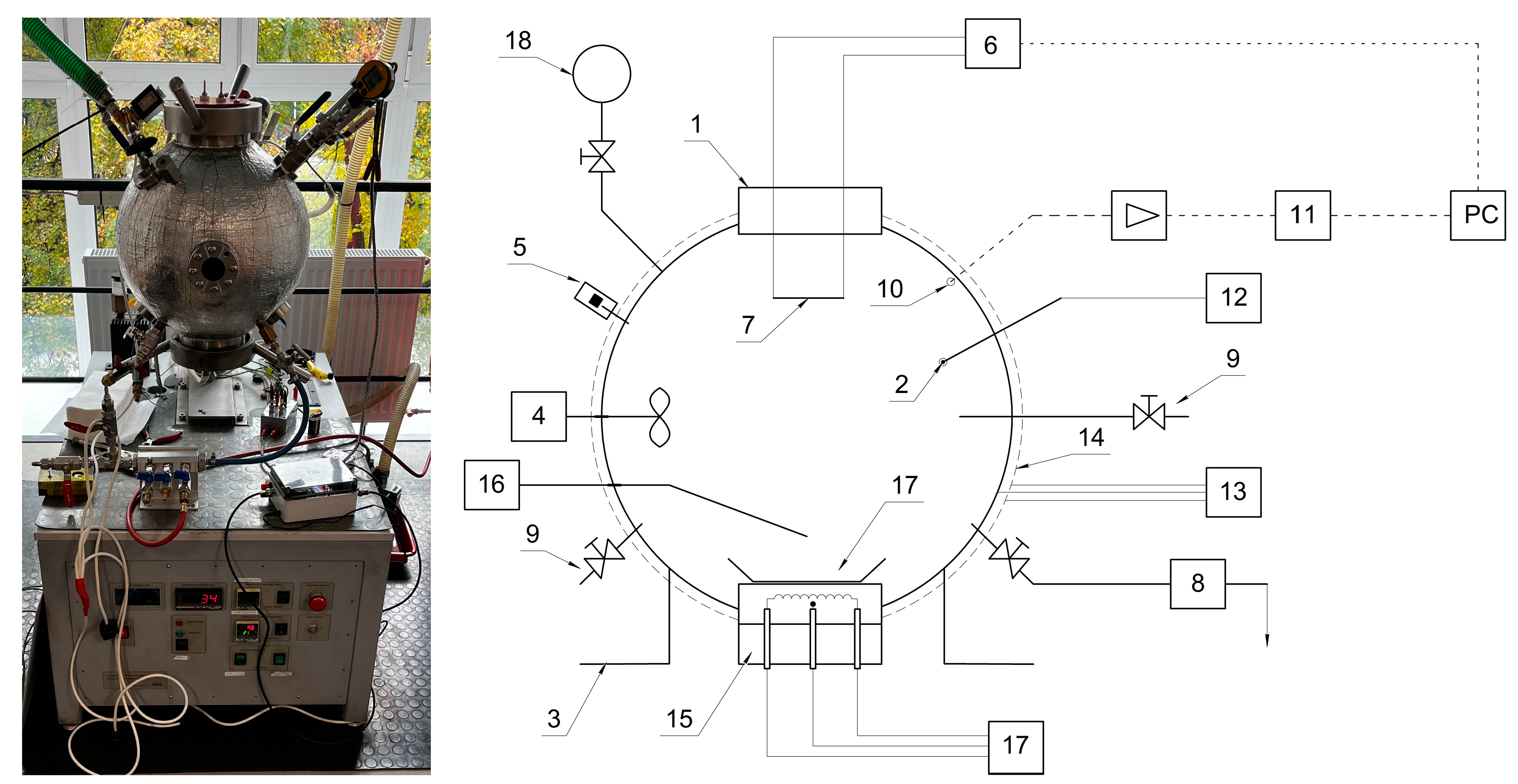
2. Materials and Methods

2.1. Governing Equations

The combustion of gases is governed by a set of equations describing the conservation of mass, momentum, energy, and species. Excluding the mass forces, baro- and thermal diffusion the equations are given by
ρ t + · ( ρ · u ) = 0
ρ · u t + · ρ · u · u = P + · τ e f f
ρ h t + · u ρ h = P t + u · P + λ e f f T i h i J i + τ e f f · u + i = 1 N Q i Q rad
ρ Y i t + · ρ u Y i = · ρ D i + μ t S c t Y i + R i
where ρ is the density [kg/m3]; u is the velocity vector; t is the time [s]; P is the pressure [Pa]; τ e f f = μ + μ t u + u T 2 / 3 I · · u is the effective stress tensor (i.e., the sum of the viscous and turbulent stresses); μ is the viscosity [Pa·s]; μt is the turbulent viscosity; I is the unit tensor; h is the enthalpy of the mixture [J]; λ e f f = λ + λ t is the effective thermal conductivity; λ is the laminar heat conductivity [J/m·s·K]; λ t = C p μ t P r t 1 is the turbulent heat conductivity; Cp is the specific heat [J/K]; P r t is the turbulent Prandtl number; T is the temperature [K]; h i = T r e f T C p , i d T , where Tref is 297 K, is the enthalpy of species i [J]; Ji is the diffusion rate vector of species i; Q i = h i 0 R i / M i is the heat of chemical reactions that species i participates in [J]; Q rad is the radiation heat [J]; Yi is the mass fraction of species i; Di is the diffusion coefficient of species i in the mixture [m2/s]; Sct is the turbulent Schmidt number; and Ri is the rate of production of species i by chemical reaction.
For the current study, the SST turbulence model was used, which shows good results in simulating wall surface flows. According to this model, the turbulent viscosity is calculated as [13]
μ T = 0.31 ρ k max 0.31 ω ; Ω F 2
where F 2 = tanh ( a r g 2 2 ) ; arg 2 = max 2 k 0.09 ω y ; 500 ν y 2 ω ; this function equals one for the boundary layer, and it equals zero for the free layer; Ω = ( u / n ) is the derivative of the flow rate on the normal to the wall; k and ω are the turbulence kinetic energy and the specific dissipation rate, respectively.
Parameters k and ω were obtained from the following transport equations:
ρ k t + x i ρ v i k = τ i j v i x j β * ρ ω k + x i μ + σ k μ t k x i
ρ ω t + x i ρ v i ω = γ ν τ τ i j v i x j β ρ ω 2 + x i μ + σ ω μ t ω x i + 2 ρ ( 1 F 1 ) σ ω 2 1 ω k x j ω x j
where ν τ = a 1 k max a 1 ω ; u / y F 2 ; the model constant ΦSST  γ , σ k , σ ω , β , β * is associated with k-ω model constants Φ and transformed into the k-ε model Φ as Φ S S T = Φ k ω F 1 + ( 1 F 1 ) Φ k ε ; F 1 = tanh a r g 1 4 ; arg 1 = min max k 0.09 ω y ; 500 ν y 2 ω ; 4 ρ σ ω 2 k C D k ω y 2 ; y—distance to the nearest wall [m]; C D k ω = max 2 ρ σ ω 2 1 ω k x j ω x j , 1 0 20 .
For combustion simulation, we used a Premixed FGM (Flamelet-Generated Manifold) model in Reaction Progress Variable Space, which solves a transport equation for the mean reaction progress variable, c ¯ , as well as the mean mixture fraction and the mixture fraction variance f 2 ¯ . Ahead of the flame ( c ¯ = 0 ), the fuel and oxidizer are mixed but unburnt, and behind the flame ( c ¯ = 1 ), the mixture is burnt.
The reaction progress variable is defined as a normalized sum of the product species mass fractions [20]:
c = k α k ( Y k Y k u ) k α k ( Y k e q Y k u ) = Y c Y c e q
where superscript u denotes the unburnt reactant.
Y k denotes the k t h species mass fraction.
Superscript e q denotes chemical equilibrium at the flame.
α k is a constant that is typically zero for reactants and unity for a few product species.
For cases, such as H 2 combustion, Ansys Fluent uses α k = 0 for all species other than α H O 2 = 10 and α H 2 O = 1 , by default.
Premixed flame equations can be transformed from physical space to reaction progress space, neglecting differential diffusion [21,22]:
ρ Y k t + Y k c ω ˙ c = ρ χ C 2 Y k c 2 + ω ˙ k
ρ T t + T c ω ˙ c = ρ χ C 2 T c 2 1 C p k h k ω ˙ k + ρ χ C C p C p c + k C p , k Y k c T c s
where Y k is the k t h species mass fraction, T is the temperature, ρ is the fluid density, t is time, ω ˙ k is the k t h species mass reaction rate, h k is the total enthalpy, and C p , k is the k t h species-specific heat at constant pressure.
The scalar dissipation rate, χ C , in Equations (9) and (10) is defined as
χ C = λ ρ C p c 2
where λ is the thermal conductivity.

2.2. Solver Settings

In this study, combustion simulations were conducted for hydrogen fuel gas and air as the oxidant using the ANSYS Fluent 2024 R2 commercial software for numerical analysis [20]. The GRI-Mech 3.0 mechanism was used as a chemical kinetics [23], with thermodynamic properties of all species defined using fourth-degree polynomial functions [23].
The computational grid near the wall was constructed following the y+ spacing recommendations for the Shear Stress Transport (SST) turbulence model. Transient analysis was utilized for simulations, with a time step of 10−5 s to handle steep pressure and velocity gradients effectively. A pressure-based solver was applied.
Table 1 summarizes the parameters in terms of the ANSYS software product [20] used for the solver in this study.
To reduce computational resources during the development of the model, we considered a ¼ section of a Constant-Volume Combustion Bomb (CVCB) with symmetrical boundaries on its sides (Figure 1a). Hybrid poly-hexacore mesh with 557,672 cells was used (Figure 1b).

3. Results and Discussion

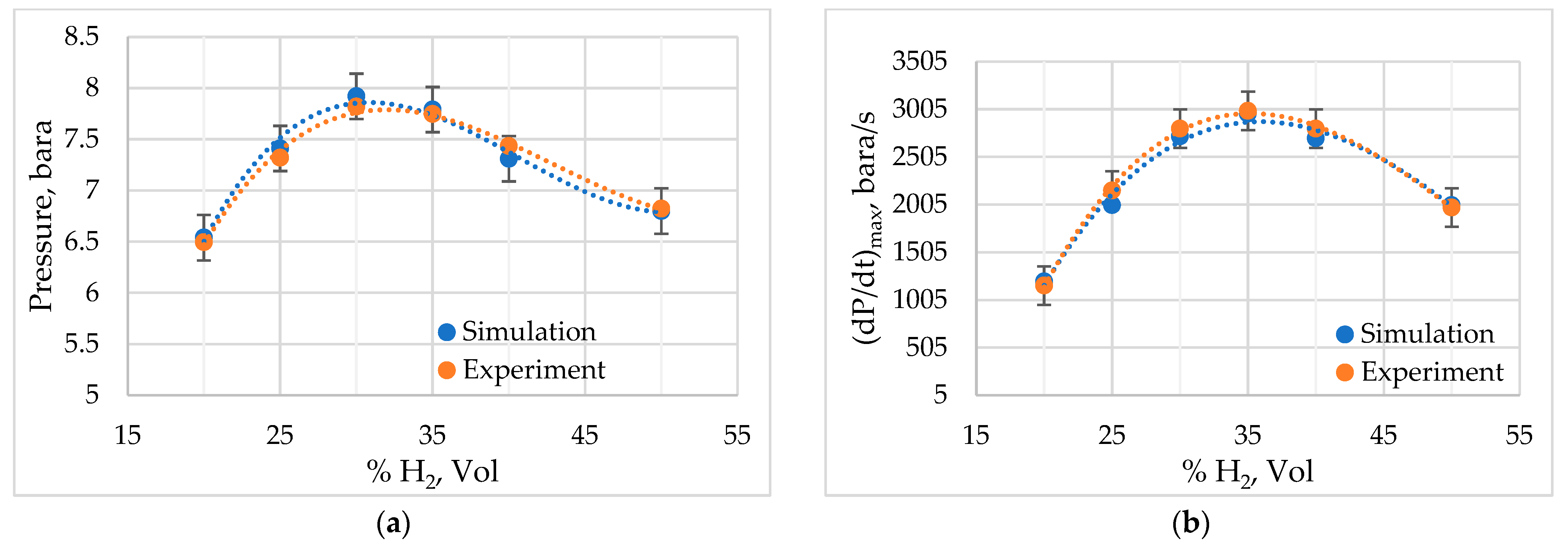
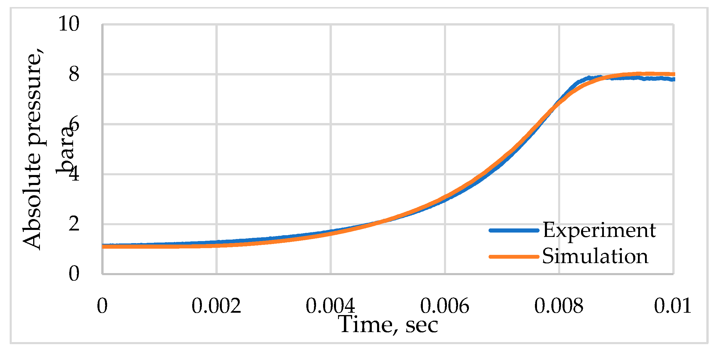
3.1. Model Verification

Experimental measurements were performed in a 20 L spherical explosion [24] vessel that complies with EN 15967 recommendations [25]. A picture and scheme of the testing apparatus are shown in Figure 2. The ignition source was supplied by overvoltage of a fuse wire of type Kanthal D with 0.2 mm diameter. The equipment is manufactured and now is located in the Institute of Heat Engineering, Faculty of Power and Aeronautical Engineering, Warsaw University of Technology, Warsaw, Poland.
The apparatus includes a safety module, a mixture preparation system, and a data acquisition system. The safety module features a bursting membrane with an activation pressure set at 20 bars. The mixture preparation system comprises a pressure transducer, a signal amplifier, and a computer designed to record phenomena at an appropriate sampling frequency. Recorded signals were processed using a smoothing algorithm based on the moving average method. The data acquisition system operates using the partial pressure method.
Experiments were primarily conducted for the cases outlined in Table 2.
During the simulation, pressure was monitored inside the bomb at the point which corresponds to the location of the pressure sensor on the experimental setup.
We can observe spherical propagation of the flame. The instances of temperature profiles inside the chamber at mixture combustion for 0.1 MPa initial pressure are shown in Figure 3.
Comparison of the numerical and experimental pressure profiles is shown in Figure 4 and Figure 5. According to the standard EN 15967 [25], the maximum pressure Pmax and the maximum dynamics of the pressure rise (dP/dt)max as well at P(t) values were provided to confirm the possibility of using the developed model for further calculations.
The obtained experimental and simulation results demonstrate a good match and satisfy requirements provided in standard EN 15967. This confirms the applicability of the proposed model in further investigations.

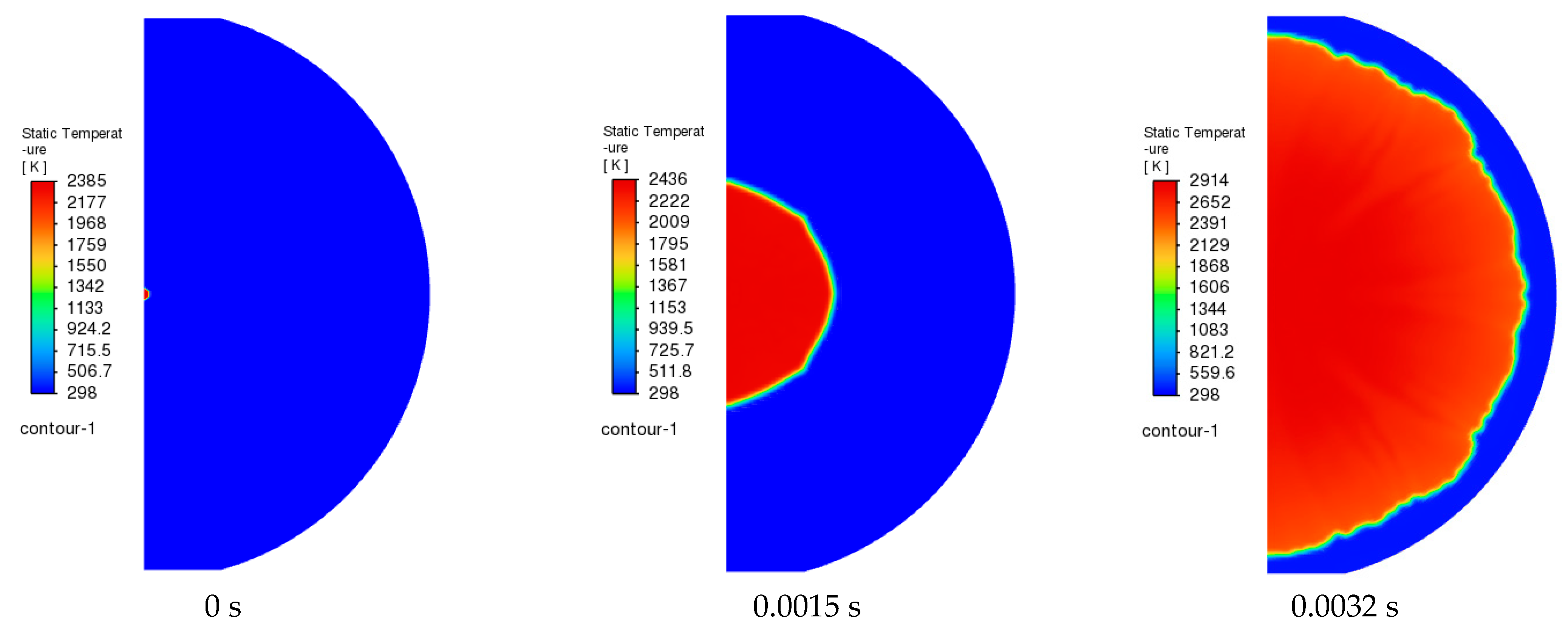
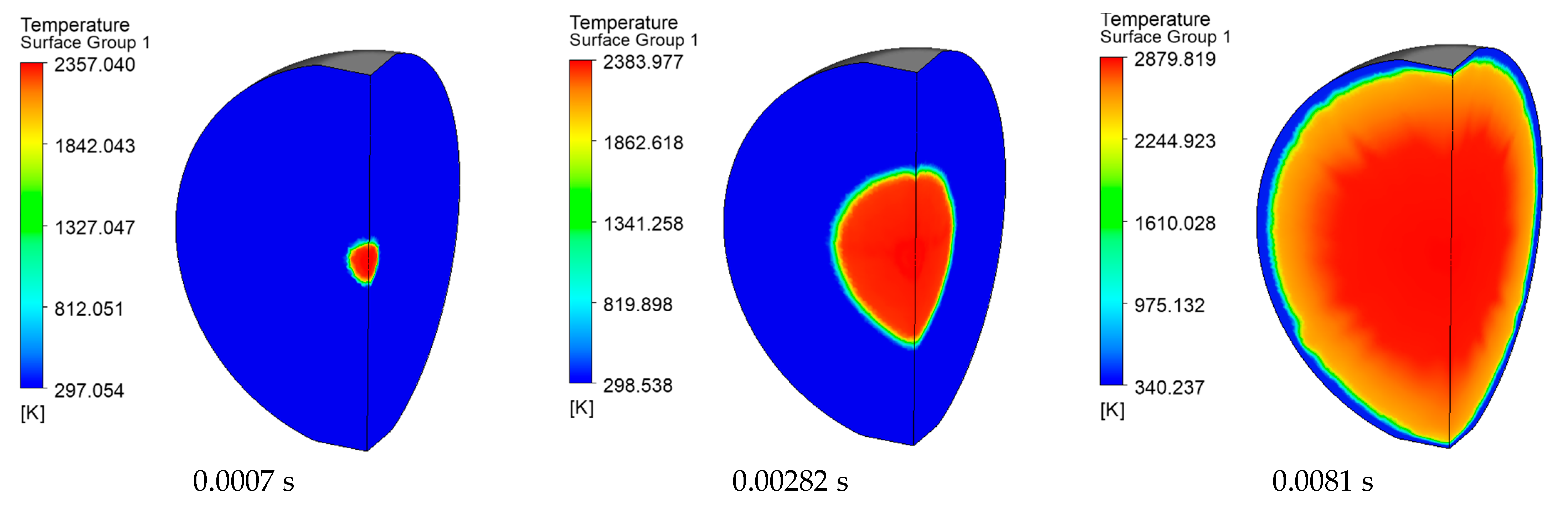
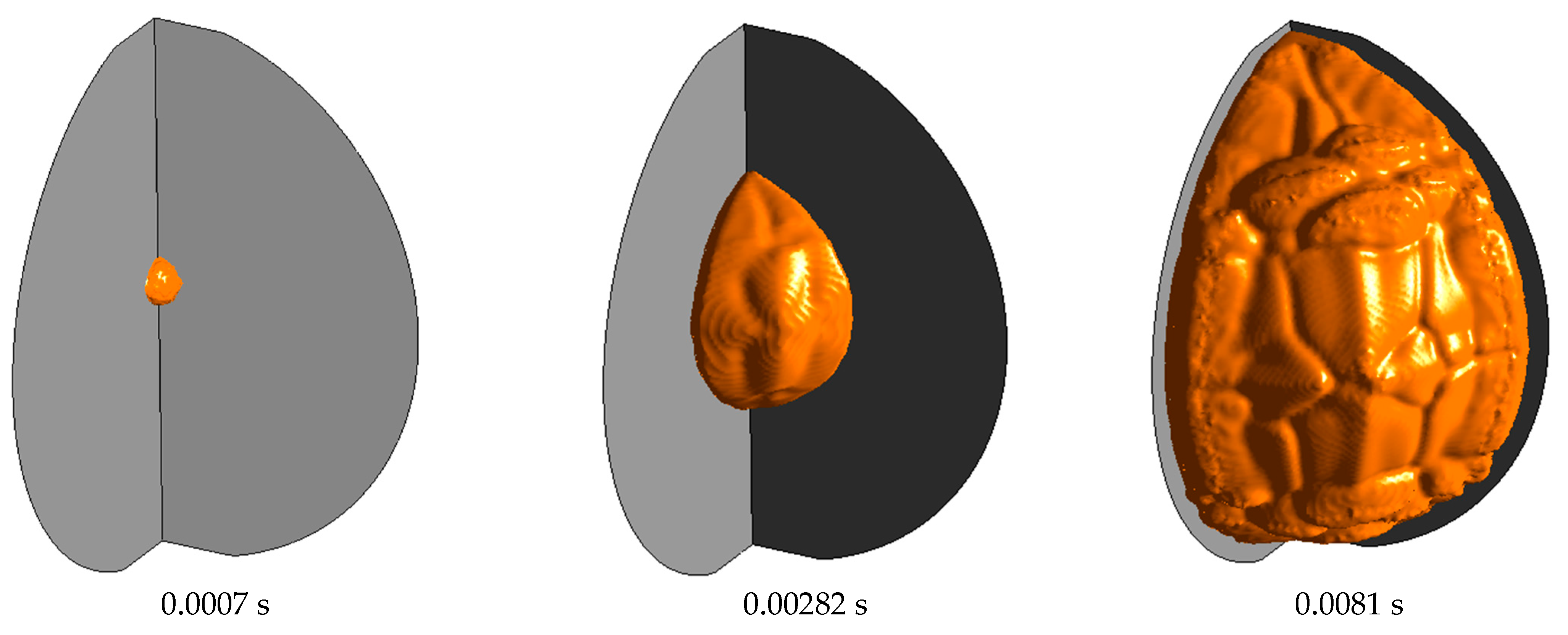
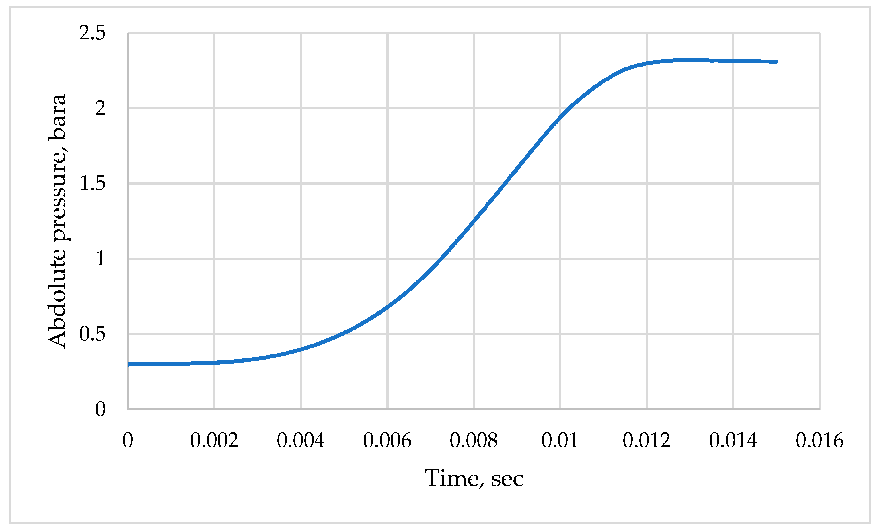
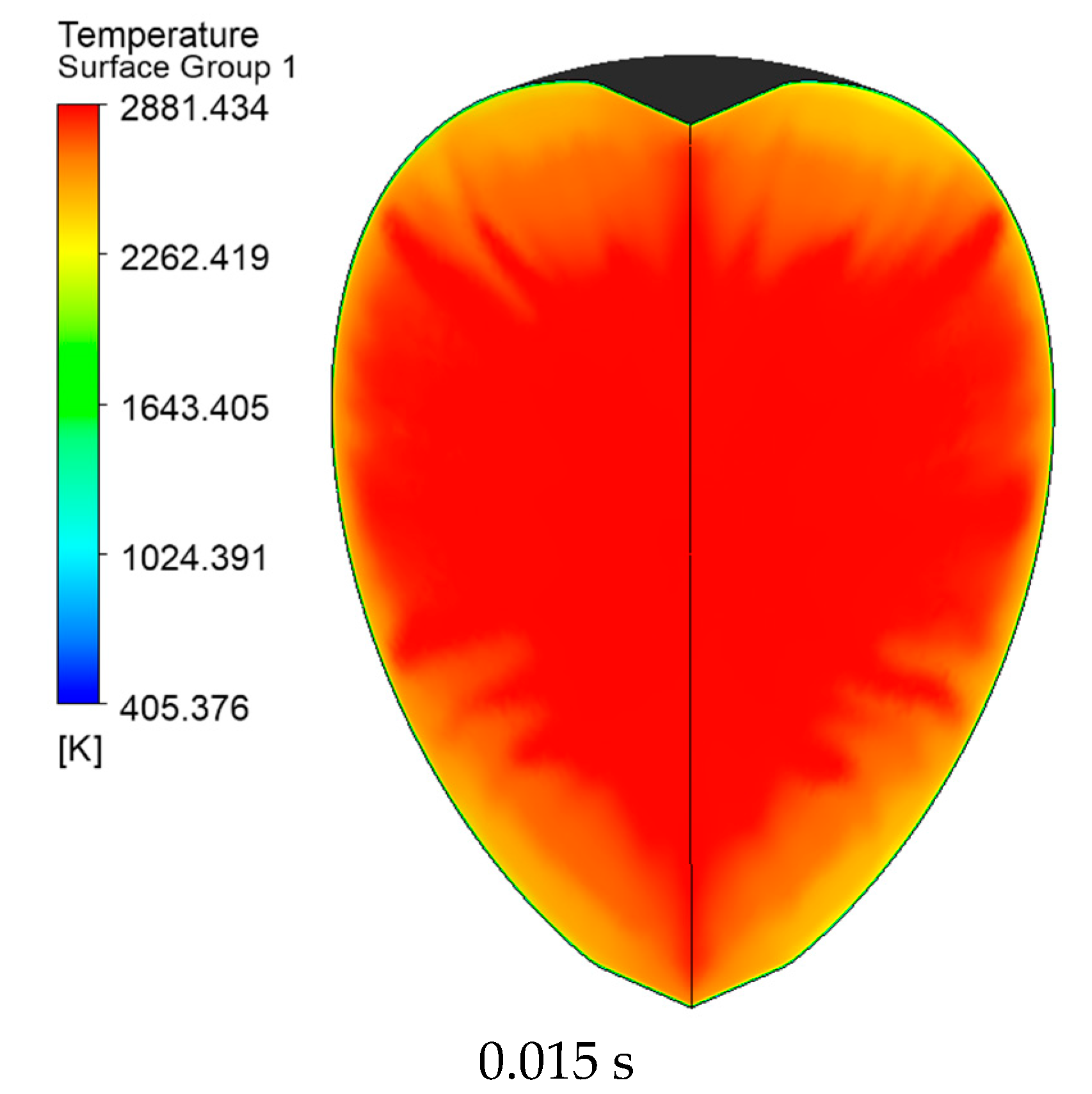
3.2. Simulation of the Stoichiometric Hydrogen–Air Mixture Combustion at Low Initial Pressure

The next task of this study is to estimate pressure and temperature distribution profiles during combustion in the same 20 L chamber but at low initial pressure according to the requirements for plastic treatment. TEM treatment of plastics is usually carried out at low initial mixture pressure [18]. So, the for current study, we chose the case listed in Table 3. The same computational geometry (Figure 1a) and hybrid poly-hexacore computation mesh (Figure 1b) were used.
Previous investigations [19] show that by providing a required holding time, the mixture inside the chamber becomes homogeneous and immovable. This assumption was used for the current hydrogen–air simulation.
The obtained temperature pattern is shown in Figure 6. The flame front becomes turbulent and acquires a cellular structure (Figure 7). Pressure inside the chamber rises over time and reaches its maximum value 0.013 s after ignition. A pressure vs. time diagram at combustion of the hydrogen–air mixture in the chamber is shown in Figure 8.
Combustion in a closed chamber leads to an uneven temperature distribution of the reaction products (Figure 9). When ignition occurs, the burning rate of the fuel mixture is governed by the flame propagation speed. Since the combustion speed is significantly lower than the speed of sound, the pressure within the chamber equalizes uniformly at any given moment. Essentially, combustion takes place within a thin layer known as the flame front. This process occurs layer by layer, with each reacting sequentially. This type of combustion is referred to as layered combustion [26].
An elementary gas layer that burns immediately after ignition reaches a reaction product temperature determined by the pressure under which it combusted. Subsequent temperature increases in this layer occur due to adiabatic compression caused by neighboring layers, which compress as pressure rises from the ongoing combustion of adjacent layers. This compression continues until the entire fuel mixture has burned and the chamber reaches the final pressure.
Notably, layers that burn last do not undergo additional compression after the reaction is complete. Their temperature remains unchanged, dictated solely by the initial conditions before combustion began. Consequently, after the entire fuel mixture combusts in a closed chamber, the reaction products exhibit varying temperatures. Layers near the ignition point, which burn first and experience adiabatic compression, have higher temperatures, whereas distant layers that burn last have lower temperatures. This phenomenon, known as the Mach effect [26], is crucial when determining the placement of plastic parts within the chamber of a TEM machine.
Future research will focus on experimental and numerical studies of hydrogen–air mixture combustion in the presence of plastic parts inside the chamber.

4. Conclusions

A mathematical model for the combustion of a hydrogen–air mixture in a closed chamber under low initial pressure has been developed and validated by comparing simulation results with experimental data. The close alignment of the Pmax and (dP/dt)max values between simulations and experiments meets the EN 15967 standard [25] requirements, confirming the model’s reliability for further research.
The simulation focused on hydrogen–air mixture combustion under low initial pressure conditions within the combustion chamber. The computational model enables the evaluation of pressure dynamics and the generation of temperature distribution profiles at any given moment. This capability supports more precise planning for part placement in TEM equipment chambers across various initial conditions.

Author Contributions

Conceptualization, O.S.; methodology, O.T. and O.S.; experimental investigation and software, V.G.; validation, O.T.; resources, V.G., D.T. and V.M.; data curation, O.T. and O.S.; writing—original draft preparation, O.S. and O.T.; writing—review and editing, D.T. and V.M.; visualization, O.T.; experimental investigation and supervision, A.T. and W.R.; project administration, O.S.; funding acquisition, O.S. All authors have read and agreed to the published version of the manuscript.

Funding

This project has received funding through the EURIZON project, which is funded by the European Union under grant agreement No. 871072. The study was partially supported by the European Union Assistance Instrument for the Fulfillment of Ukraine’s Commitments in the Horizon 2020 Framework Program for Research and Innovation of the European Union as a part of the scientific research project No. 0124U004371.

Data Availability Statement

The data presented in this study are available on request from the corresponding author.

Acknowledgments

The authors express their gratitude to CADFEM UA LLC, the Channel Partner of Ansys Inc. in Ukraine, for help with the software licensing.

Conflicts of Interest

The authors declare no conflicts of interest.

References

  1. Li, S.; Li, X.; Jin, H.; Liu, Y.; Wu, Y. A Numerical Simulation Study on the Combustion of Natural Gas Mixed with Hydrogen in a Partially Premixed Gas Water Heater. Energies 2024, 17, 4069. [Google Scholar] [CrossRef]
  2. Ma, X.; Nie, B.; Wang, W.; Zhao, D.; Zhang, Y.; Yang, Y.; Ma, C.; Hu, B.; Chang, L.; Yang, L. Effect of hydrogen concentration, initial pressure and temperature on mechanisms of hydrogen explosion in confined spaces. Combust. Flame 2024, 269, 113696. [Google Scholar] [CrossRef]
  3. Han, H.; Ma, Q.; Qin, Z.; Li, Y.; Kong, Y. Experimental study on combustion and explosion characteristics of hydrogen-air premixed gas in rectangular channels with large aspect ratio. Int. J. Hydrogen Energy 2024, 57, 1041–1050. [Google Scholar] [CrossRef]
  4. Swaminathan, S.; Spijker, C.; Gruber, M.; Kofler, I.; Raupenstrauch, H. Numerical Simulation and Performance Evaluation of Hydrogen-Enriched Natural Gas for an Industrial Burner in a Testing Chamber. Energies 2023, 16, 6380. [Google Scholar] [CrossRef]
  5. Giacomazzi, E.; Troiani, G.; Di Nardo, A.; Calchetti, G.; Cecere, D.; Messina, G.; Carpenella, S. Hydrogen Combustion: Features and Barriers to Its Exploitation in the Energy Transition. Energies 2023, 16, 7174. [Google Scholar] [CrossRef]
  6. Ricci, F.; Zembi, J.; Avana, M.; Grimaldi, C.N.; Battistoni, M.; Papi, S. Analysis of Hydrogen Combustion in a Spark Ignition Research Engine with a Barrier Discharge Igniter. Energies 2024, 17, 1739. [Google Scholar] [CrossRef]
  7. Chijioke, E.G.; Teodorczyk, A. CFD simulation of a vortex-controlled diffuser for a jet engine burner. Combust. Engines 2023, 195, 71–82. [Google Scholar] [CrossRef]
  8. Rudy, W.; Pekalski, A.; Makarov, D.; Teodorczyk, A.; Molkov, V. Prediction of Deflagrative Explosions in Variety of Closed Vessels. Energies 2021, 14, 2138. [Google Scholar] [CrossRef]
  9. Reyes, M.; Tinaut, F.V.; Horrillo, A.; Lafuente, A. Experimental characterization of burning velocities of premixed methane-air and hydrogen-air mixtures in a constant volume combustion bomb at moderate pressure and temperature. Appl. Therm. Eng. 2018, 130, 684–697. [Google Scholar] [CrossRef]
  10. Kamran, M.; Turzynski, M. Exploring hydrogen energy systems: A comprehensive review of technologies, applications, prevailing trends, and associated challenges. J. Energy Storage 2024, 96, 112601. [Google Scholar] [CrossRef]
  11. Amzin, S.; Mohd Yasin, M.F. Modelling of a Bluff-Body Stabilised Premixed Flames Close to Blow-Off. Computation 2021, 9, 43. [Google Scholar] [CrossRef]
  12. Di Nardo, A.; Calabrese, M.; Venezia, V.; Portarapillo, M.; Turco, M.; Di Benedetto, A.; Luciani, G. Addressing Environmental Challenges: The Role of Hydrogen Technologies in a Sustainable Future. Energies 2023, 16, 7908. [Google Scholar] [CrossRef]
  13. Shen, H.; Crespo del Granado, P.; Jorge, R.S.; Loffler, K. Environmental and climate impacts of a large-scale deployment of green hydrogen in Europe. Energy Clim. Change 2024, 5, 100133. [Google Scholar] [CrossRef]
  14. Freitag, P.; Stolle, D.; Kullmann, F.; Linssen, J.; Stolten, D. A techno-economic analysis of future hydrogen reconversion technologies. Int. J. Hydrogen Energy 2024, 77, 1254–1267. [Google Scholar] [CrossRef]
  15. Plankovskyy, S.; Popov, V.; Shypul, O.; Tsegelnyk, Y.; Tryfonov, O.; Brega, D. Advanced thermal energy method for finishing precision parts. In Advanced Machining and Finishing; Gupta, K., Pramanik, A., Eds.; Elsevier: Amsterdam, The Netherlands, 2021; pp. 527–575. [Google Scholar] [CrossRef]
  16. Plankovskyy, S.; Shypul, O.; Tsegelnyk, Y.; Brega, D.; Tryfonov, O.; Malashenko, V. Basic Principles for Thermoplastic Parts Finishing With Impulse Thermal Energy Method. In Handbook of Research on Advancements in the Processing, Characterization, and Application of Lightweight Materials; Kumar, K., Babu, B., Davim, J., Eds.; IGI Global: Hershey, PA, USA, 2022; pp. 49–87. [Google Scholar] [CrossRef]
  17. Galliková, J.; Grenčík, J.; Barta, D.; Barlok, M. FMECA analysis of thermal deburring machine EXTRUDE HONE TEM P-350. Sci. J. Marit. Univ. Szczec. 2020, 63, 9–16. [Google Scholar] [CrossRef]
  18. Kulik, P. Thermal Deburring Machine and Method of Thermal Deburring. WO Patent 2019/054886, 21 March 2019. [Google Scholar]
  19. Shypul, O.; Garyn, V.; Tryfonov, O.; Myntiuk, V.; Egedy, A. Study of the green hydrogen-air mixture formation in closed chamber with given composition. Hung. J. Ind. Chem. 2024, 52, 57–62. [Google Scholar] [CrossRef]
  20. Fluent Theory Guide. Available online: https://ansyshelp.ansys.com/account/secured?returnurl=/Views/Secured/corp/v242/en/flu_th/flu_th.html (accessed on 29 October 2024).
  21. Nguyen, P.; Vervisch, L.; Subramanian, V.; Domingo, P. Multi-Dimensional Flamelet-Generated Manifolds for Partially Premixed Combustion. Combust. Flame 2010, 157, 43–61. [Google Scholar] [CrossRef]
  22. Lodier, G.; Vervisch, L.; Moureau, V.; Domingo, P. Composition-Space Premixed Flamelet Solution with Differential Diffusion for In Situ Flamelet-Generated Manifolds. Combust. Flame 2011, 158, 2009–2016. [Google Scholar] [CrossRef]
  23. Available online: http://combustion.berkeley.edu/gri-mech/version30/text30.html (accessed on 10 November 2024).
  24. Grabarczyk, M.; Żbikowski, M.; Mężyk, Ł.; Teodorczyk, A. Temperature effect on explosion parameters of hydrogen-air deflagrations in presence of water vapor. Chall. Mod. Technol. 2016, 7, 39–44. [Google Scholar] [CrossRef]
  25. BS EN 15967:2011; Determination of Maximum Explosion Pressure and the Maximum Rate of Pressure Rise of Gases and Vapors. BSI: London, UK, 2012.
  26. Tryfonov, O.; Sastela, O. Simulaiton of Gas Mixtures Combustion in a Closed Combustion Chamber of Thermal Pulse Equipment. Open Information and Computer Integration Technologies No 72. 2016, pp. 141–149. Available online: https://dspace.library.khai.edu/xmlui/bitstream/handle/123456789/5330/p141-149.pdf?sequence=1&isAllowed=y (accessed on 12 January 2025).
Figure 1. (a) Computational domain; (b) computational mesh. Pink and yellow colors mean symmetry planes, blue color means cross-section plane.
Computation 13 00054 g001
Figure 2. Apparatus picture and scheme with description: (1) upper head of reactor carrying ignition source module; (2) thermocouple for measuring temperature inside the reactor; (3) supports on which chamber is founded; (4) homogenizing system for preparation of tested mixtures; (5) safety module; (6) trigger for initiating data acquisition system coupled with ignition system; (7) ignition source; (8) vacuum pump; (9) 1/2” sockets for connecting additional components or modules if needed; (10) dynamic pressure sensor with signal transducer and analog amplifier; (11) data acquisition system that links PC with dynamic pressure sensor; (12) device for regulation of measured value of temperature inside reactor; (13) system for temperature stabilization of testing reactor (immersion heaters, thermocouples and digital controller); (14) thermal insulation of reactor; (15) lower head with evaporation module (not used in current study); (16) system for feeding H2O component in its liquid state into evaporation module (not used in current study); (17) evaporation module (heated tray with temperature stabilization system, not used in current study); (18) pressure gauge for measuring static pressure inside reactor (disconnected during actual measurement). Reproduced with permission from prof. Andrzej Teodorczyk, Challenges of Modern Technology; published by Foundation for Young Scientists, 2016. [24].
Computation 13 00054 g002
Figure 3. The instances of static temperature profiles at mixture combustion (0.15 MPa initial pressure).
Computation 13 00054 g003
Figure 4. Comparison of the numerical and experimental results: (a) Pmax vs. H2 volume fraction; (b) (dP/dt)max vs. H2 volume fraction.
Computation 13 00054 g004
Figure 5. Absolute pressure vs. time diagram.
Computation 13 00054 g005
Figure 6. Instances of static temperature profiles at hydrogen–air mixture combustion in industrial chamber.
Computation 13 00054 g006
Figure 7. The instances of the flame front structure at hydrogen–air mixture combustion in the industrial chamber.
Computation 13 00054 g007
Figure 8. Pressure vs. time diagram at hydrogen–air mixture combustion in industrial chamber.
Computation 13 00054 g008
Figure 9. Uneven temperature distribution of the reaction products after combustion.
Computation 13 00054 g009
Table 1. Summary of solver parameters.
ParameterValue
SolverPressure-based (segregated)
Pressure–Velocity couplingCOUPLED
Spatial discretizationSecond-order/second-order UPWIND
Temporal discretizationSecond-order implicit
Gradient discretizationLeast-squares cell-based
Table 2. Summary of considered cases for model verification.
Case #H2 Volume FractionInitial PressureInitial Mixture Temperature
Case # 120%0.1 MPa25 °C
Case # 225%0.1 MPa25 °C
Case # 330%0.1 MPa25 °C
Case # 435%0.1 MPa25 °C
Case # 540%0.1 MPa25 °C
Case # 650%0.1 MPa25 °C
Table 3. Summary of considered case for simulation of stoichiometric hydrogen–air combustion at low initial mixture pressure.
Case #Initial PressureInitial Mixture Temperature
Case # 10.3 bara297 K
Disclaimer/Publisher’s Note: The statements, opinions and data contained in all publications are solely those of the individual author(s) and contributor(s) and not of MDPI and/or the editor(s). MDPI and/or the editor(s) disclaim responsibility for any injury to people or property resulting from any ideas, methods, instructions or products referred to in the content.

