Article

An Optical Camera Communication Using Novel Hybrid Frequency Shift and Pulse Width Modulation Technique for Li-Fi

Department of Information Technology, National Institute of Technology Karnataka, Mangaluru 575025, Karnataka, India
*
Author to whom correspondence should be addressed.
Computation 2022, 10(7), 110; https://doi.org/10.3390/computation10070110
Submission received: 7 May 2022 / Revised: 25 June 2022 / Accepted: 28 June 2022 / Published: 30 June 2022

Abstract

:
With an increase in network-connected devices, the existing Radio Frequency (RF) spectrum is getting highly saturated. Non-RF-based communication systems have recently garnered attention as they can be considered an alternative to RF-based systems for some applications. The availability of efficient and low-cost electronic components like Light Emitting Diode (LED), photodiode, and cameras have been pivotal in building communications systems using visible light. High-speed communication using visible light can be achieved with customized hardware and software. Visible Light Communication (VLC) uses various properties of light to encode digital data, which is then modulated and transmitted over a short distance to the receiver. Photodiodes are inexpensive and provide low complexity implementation, but their adoption requires modifying existing devices to house dedicated sensors. On the other hand, in Optical Camera Communication (OCC), existing camera-based receivers are used to extract encoded data using properties of light like color, blink frequency, intensity, and polarity. In this paper, a novel OCC technique to achieve improved robustness using a Hybrid Frequency Shift Pulse Width Modulation (HFSPDM) is proposed, implemented, and evaluated. The performance of the proposed technique is compared for a short distance with On-Off Keying (OOK) and Binary Frequency Shift-OOK (BFSOOK) due to similar computational requirements. It was observed that the proposed technique used a 17% lesser number of frames than BFSOOK and provided 8% better BER than OOK under a test environment. It also supports longer distance communication than OOK as it is less sensitive to external noise.

1. Introduction

As the technology around us continues to evolve in size, portability, intelligence, and efficiency, the next logical thing is to find a new purpose for existing components to improve their usability. With the advent of LEDs, researchers have started exploring its properties for establishing data communication between devices which gave rise to the complete new domain of VLC. Increasing interest in VLC has led to a need to revamp the previously existing modulation techniques, posing more unique challenges specific to the nature of visible light. However, the receiver side adoption of VLC is strictly limited to implementation based on Photodiode or Camera. Photodiodes are inexpensive and provide low complexity implementation for VLC as the modulation techniques are based on light intensity. In this case, achieving higher data rates is constrained to the response time of the photodiode [1,2,3]. On the other side, exploration of other light properties such as color has shown promising results in terms of better data rate, Refs. [4,5] but as photodiodes are limited to sensing only light intensities, other techniques had to be explored.
OCC is considered one possible solution towards achieving a ready-to-use Li-Fi system by utilizing the camera’s properties, computational capacity of mobile phones, and chromaticity of the light [6]. Since such systems use existing cameras integrated into mobile phones, they need not require additional dedicated hardware like photodiode [7,
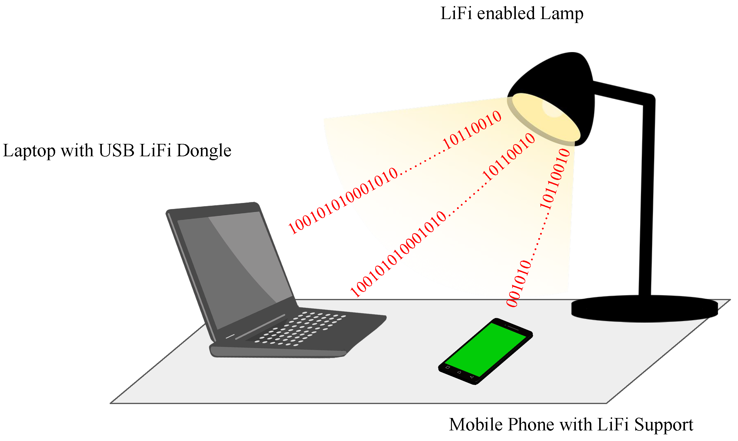
8]. These systems can be used in vehicle-to-vehicle communication, indoor localization, indoor positioning, indoor navigation and augmented reality. In a typical indoor environment, VLC Systems can be deployed as Lamps or Ceiling Lights, as shown in Figure 1. However, other challenges related to the OCC-based Li-Fi System include identifying the Li-Fi access point, adjusting exposure, and video pre-processing. This paper proposes, implements, and evaluates a novel hybrid modulation technique and compares it with the existing two modulation techniques with similar implementational complexities. The objectives of this paper are
  • To study and experimentally evaluate thresholding techniques for On-Off Keying(OOK) and Frequency Shift Keying(FSK) modulation schemes under OCC.
  • To propose and implement Hybrid Frequency Shift Pulse Duration Modulation scheme for OCC.
  • To evaluate the performance of the proposed technique based on Bit Error Ratio (%), distance, and frames per bit.
The remainder of the paper is organized as per the following structure. In Section 2, previous studies in the related domain are summarized. In Section 3, an overview of the OCC system is provided, with a basic design and description of other functional elements of the system. Section 4 discusses the design and implementation of reference modulation techniques such as OOK, FSK, and the proposed HFSPDM. Section 5 highlights the obtained experimental result of each modulation technique and provides comparative performance analysis.

2. Related Work

This section highlights previous work carried out in the domain of OCC, specifically about its challenges in adopting Li-Fi Systems, modulation techniques, and thresholding mechanisms. In paper [9], the author has provided a performance analysis of OOK modulation based on different camera parameters such as frame rate, focal length, rolling rate, and shutter speed. It was observed that the pixel intensity was higher for closer distances, resulting in a high Signal-to-Noise Ratio(SNR) and thus better data decoding. Paper [10] shows the effects of ISO exposure values on the Bit Error Rate. The experimental results demonstrated that the system observed an increase in noise, directly proportional to the camera’s sensitivity concerning ISO values and shutter speeds. In paper [11], the difference between rolling shutter vs. global shutter is discussed. Issues such as mixed symbol frames, stripe width estimation, and image pre-processing are addressed by their proposed “Rolling Lights” System. These works provided sufficient insight into the relation between camera parameters and their impact on information reconstruction. It also helped to understand the “Rolling Shutter” phenomenon and techniques used for its adaptation in OCC.
In a camera-based VLC System, the captured video/images must be processed to decode the encoded data from the light blink pattern. Matlab-based digital image processing methods such as gray-scaling, histogram equalization, and high pass filters were discussed to improve signal quality in OCC System [12]. Bummin Kim et al. [13] provided an overview and performance evaluation of three thresholding methods, namely as Background Subtraction, Polynomial Regression, and Moving Average. The Background Subtraction method, includes masking of reference frame over current frame to identify difference in intensities. Whereas, Polynomial Regression and Moving Average thresholding method directly calculates raw intensity values. It was observed that the Background Subtraction method out performed other two techniques in terms of computational speed. These works highlighted various image processing and thresholding techniques used under OCC which inspired our proposed work.
The modulation technique is crucial in providing efficient bandwidth and data rate. Various existing modulation techniques, such as OOK, FSK, and Color Shift Keying(CSK), are modified to serve OCC-based Li-Fi systems. Thus, in a simple OOK Modulation, logic 0 means light is Off, and logic 1 means light is On. These changes in the On-Off cycle produce black and white stripes in the captured image/video under tuned conditions [14]. However, in OCC, direct encoding data in OOK is complex due to the low frame rate of cameras and the flickering frequency of source light. Thus, the most common way to achieve OOK without flickering is to encode data bits in terms of frequencies. In paper [15] a frequency shift-based OOK Modulation technique is implemented and evaluated. It also provides a sub-carrier frequency design based on the relationship between bit interval and sampling interval and between Sub-carrier frequencies and flickering mitigation conditions. A binary frequency shift-based OOK (BFSOOK) [16] modulation is proposed, and experimental analysis is provided for the relation between distance and detectable stripes. The proposed system mapped each binary bit to a pair of frequencies separated by the guard band frequency, enabling the detection of data bits from the frame. In paper [17] the OOK frequencies logic 1 and 0 are selected such that when under-sampled by a low frame rate camera, these frequencies align to low pass frequencies that can then be further decoded to the original bit values.
Modulation based on the color changes is unique to VLC and Li-Fi Systems. There are different color constellations such as 4-CSK, 8-CSK, 16-CSK depending upon the number of bits mapped to a color. An experimental demonstration of a low-cost OCC system with a 2D-constellation-assisted 4-CSK transmission scheme is proposed in paper [18]. The system could achieve a BER of 3.8 × 10 3 for the distance of 0.8m and a data rate of 10.74 kb/s. A novel CSK-based OCC system is proposed in paper [19], which uses an 8-CSK modulation pattern to obtain pixel efficiency of 3.75 pixels per bit. Here, Pixel efficiency is a performance evaluation parameter for an OCC system, which is the minimum number of pixels required to represent a bit. In paper [20] an LED-to-camera Communication system called ColorBars is proposed, which addresses major challenges about color flicker, inter-frame data loss, and receiver diversity. It was observed that when ColorBars use lower CSK modulation, reliable communication is guaranteed due to the extremely low symbol error rate. These works aided metrics selection for performance evaluation of our proposed technique.
These works have provided us with sufficient insight and motivation to explore the OCC-based LiFi domain further. We have tried to contribute to this growing domain with our proposed testbed and modulation technique. Our work is inspired by these related works and attempts to extract, combine, and modify them to create a better solution.

3. Overview of OCC

This section highlights a few key issues and characteristics of OCC based Li-Fi system; this involves the Generic Architecture of the OCC System, Synchronization Issues, Encoding Principle, Decoding Principle, and Performance Evaluation Metrics for OCC.

3.1. Generic OCC Architecture

The Figure 2, shows a generalized block diagram of an OCC system. The input binary data stream is passed to Optical Signal Modulator which modulates the signal using the selected technique. The modulated signal is mapped to the LED driver which is used to control the LED. The modulated signal is transmitted over a free-space optical medium. Mobile phone cameras receive the directed light as live video. The video undergoes frame sampling and thresholding to demodulate the signal and decode the received data.

3.2. Synchronization

The primary deployment of OCC based Li-Fi systems is typically in a broadcast environment. Thus, there is no feedback channel, unlike RF communication; this limits the dynamic tuning of the receiver equipment to achieve synchronization and thus restricts achieving higher data rates. If the user device starts sampling at any point during transmission, there is a possibility of losing data; this problem is called Random Sampling [21]. On the other hand, the operational performance of each image sensor varies from product to product; this results in the problem of having different frame rates for different equipment despite the same configurations.

3.3. Encoding Principle

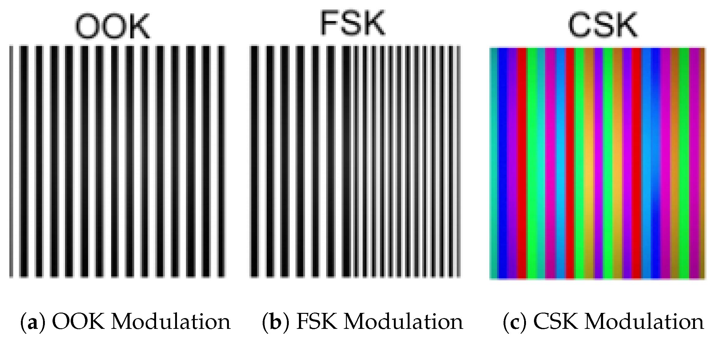
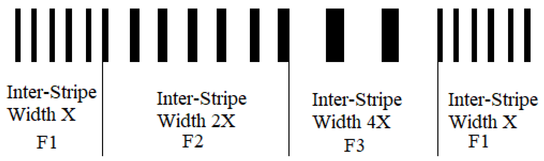
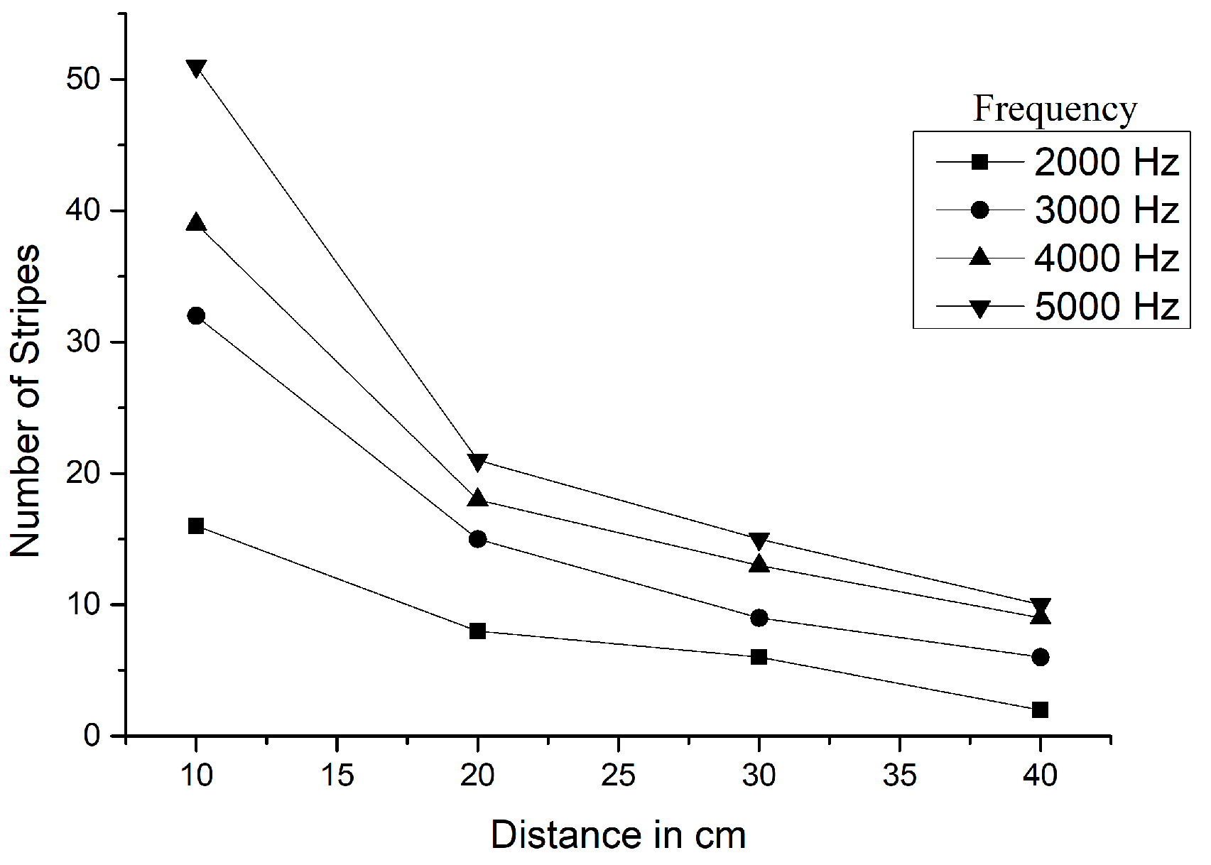
The basic encoding principle in rolling shutter-based OCC remains the same, i.e., encoding data in stripes. Thus, depending upon the modulation schemes, the properties of stripes will change. For example, in direct OOK modulation, the width of stripes will change based on the bit patterns. Whereas for FSK, the modulated output would vary in the number of stripes, and for CSK, it would be colored bands. Although the number of stripes required to represent a bit determines the efficiency of the modulation technique, it is also dependent on the size of the transmitter [22]. Figure 3 shows sample frames from each modulation scheme. In FSK, the data is transmitted by modulating the signals in-terms of shifting frequencies, while in Pulse Duration Modulation(PDM), it is transmitted by changing the duration of pulse. The proposed modulation technique combine these two techniques to transmit the data by modulating duration of frequencies.

3.4. Decoding Principle

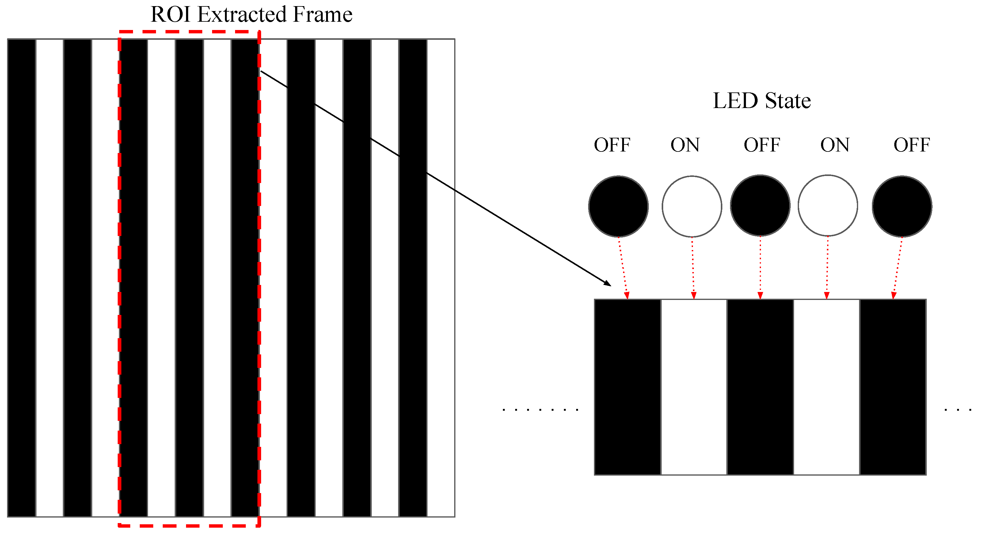
An image sensor is built with pixel arrays and a built-in read-out circuit. Each pixel of an image sensor acts as a photodetector. Depending upon the type of camera, these arrays are activated either at once or one by one; this is the basic working principle of the global shutter and rolling shutter. The pixels are activated together in the global shutter, whereas pixels are activated in succession in the rolling shutter. Rolling shutter enables capturing of LED states at different pixels resulting in a series of stripes as shown in Figure 4.
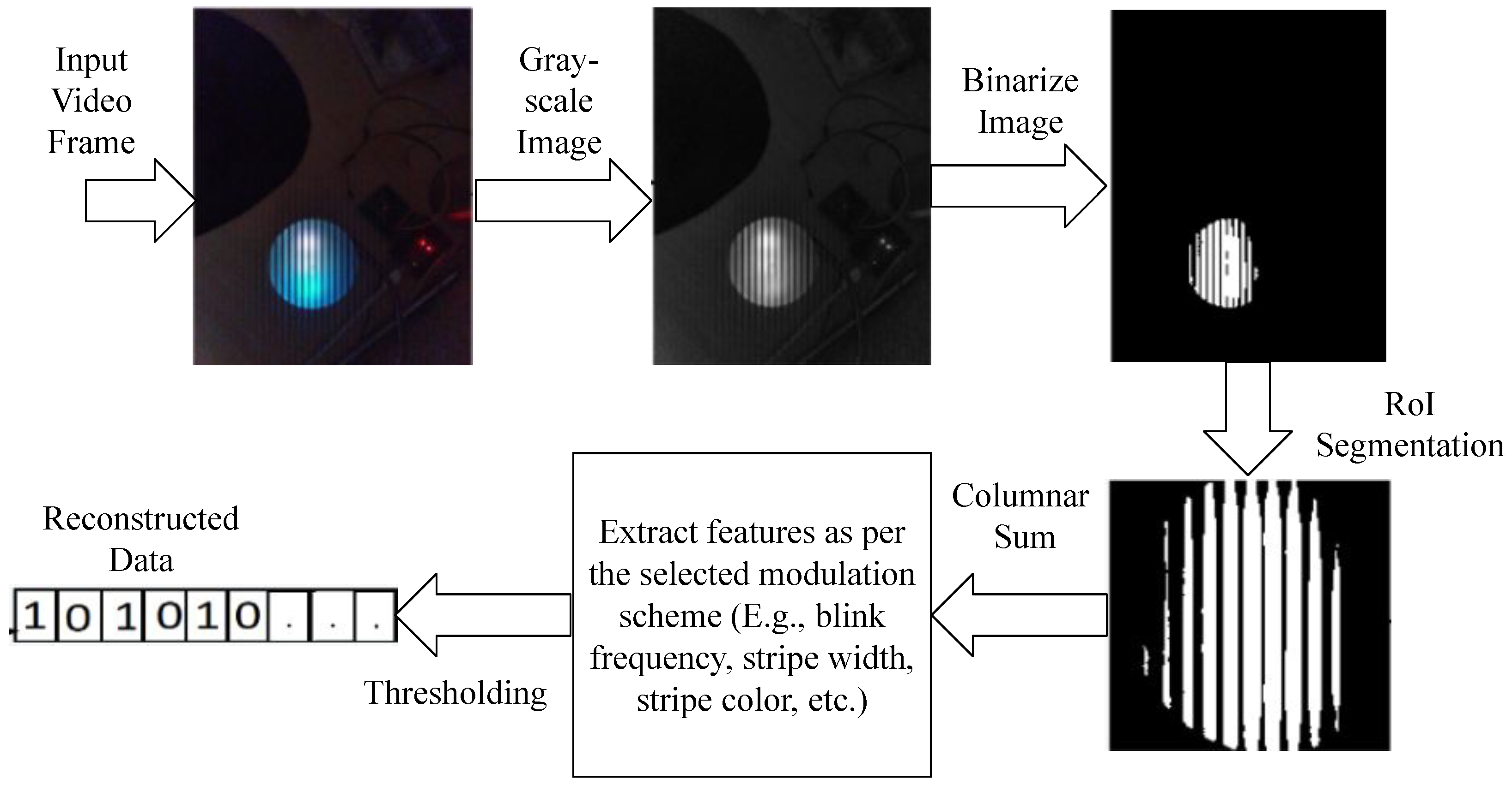
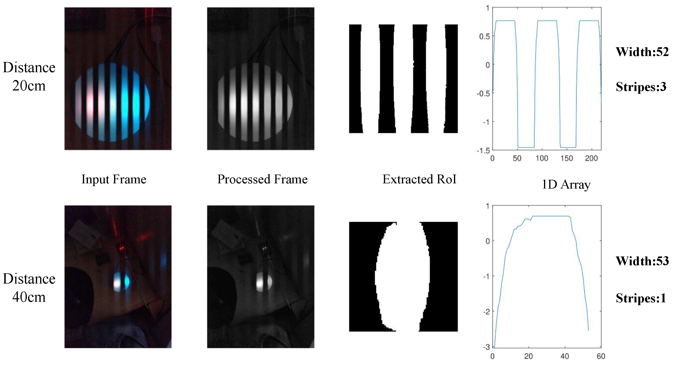
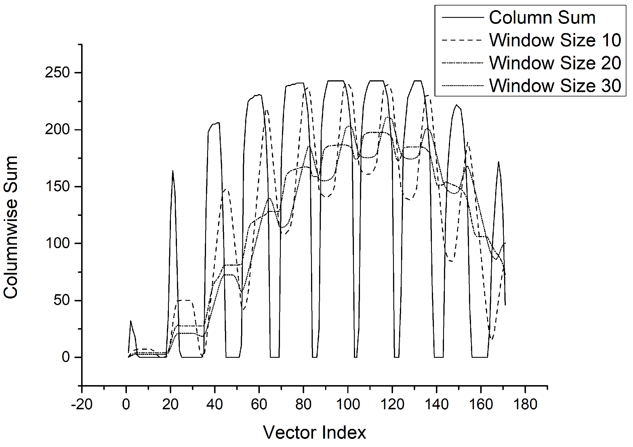
The transmitted bits are decoded using image-processing techniques as shown in Figure 5. The first step is detecting and tracking the transmitter from video frames using computer vision algorithms to identify the Region of Interest (RoI). The RoI from the image is cropped and resized to obtain an image containing stripes. The cropped RoI further undergoes pre-processing to obtain a 2D signal using thresholding and decoding techniques. The decoded binary bits are used to reconstruct sent data. Details on this process are discussed in Section 4.

3.5. Performance Evaluation Metrics

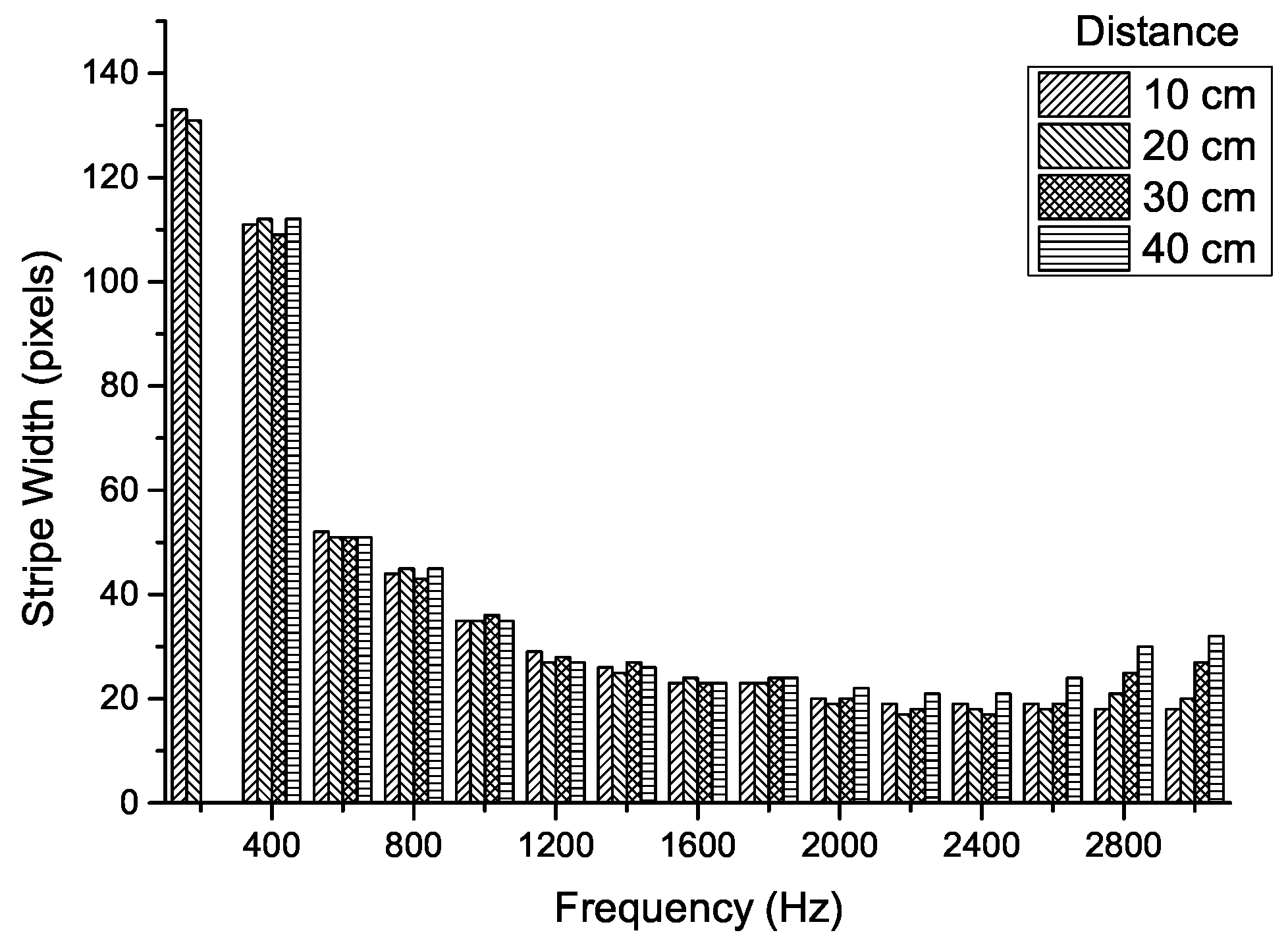
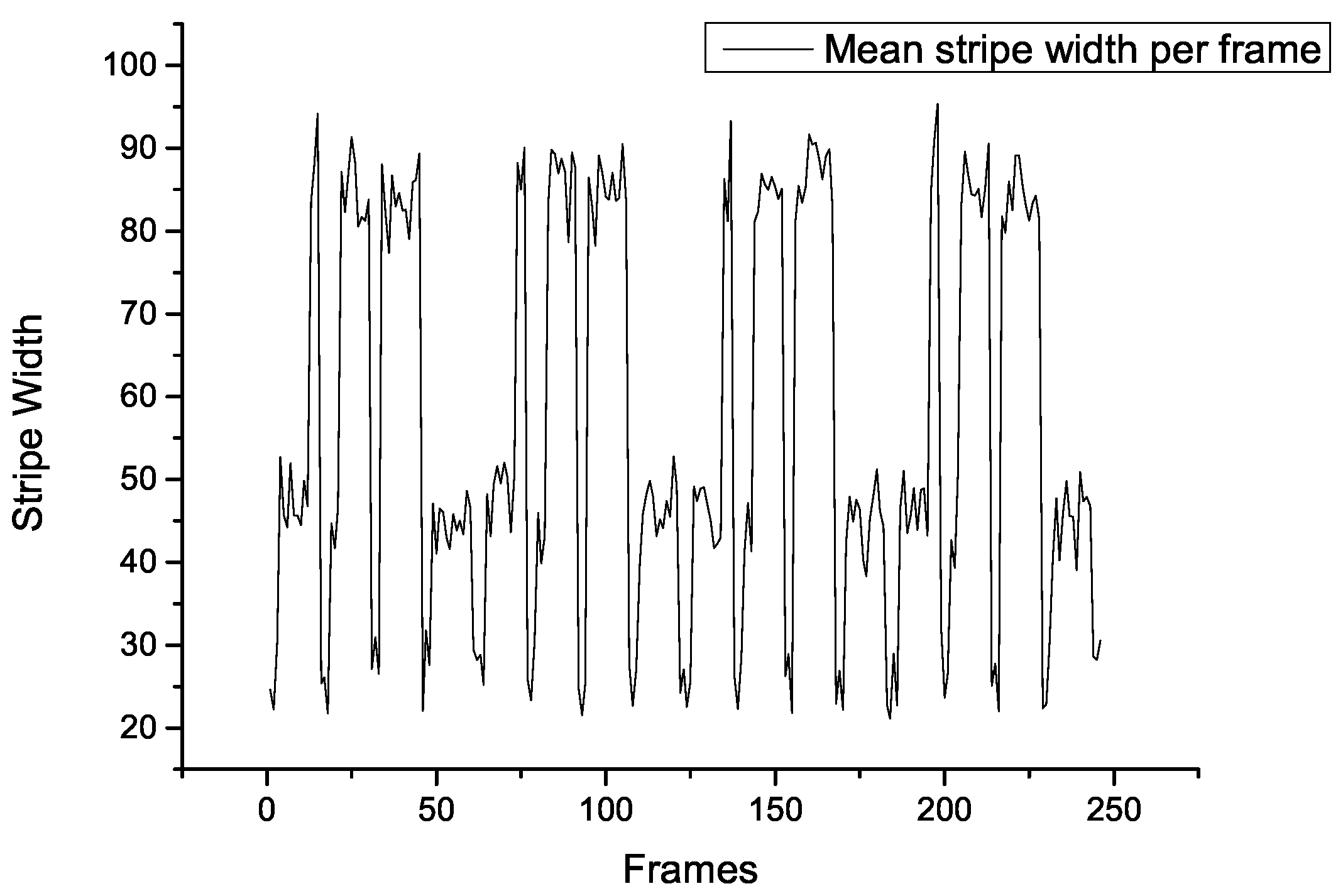
In an OCC based Li-Fi system, the number of frames required to represent a bit is the crucial factor in determining the modulation techniques’ efficiency. In a typical OCC based Li-Fi system using OOK modulation, the encoded bits are observed as stripes in the image at the receiver side. Thus, the more the stripes in the image, the more bits can be encoded. However, the width of these stripes is proportional to the LED transmitter’s symbol rate. Thus, for a higher symbol rate, the corresponding bit rate will be higher, which results in an increase in number of bits per second. Each bit is represented with the smaller duration of on-off cycles causing the stripe width to become thinner. However, due to the pixel bleeding effect, the image becomes blurred and the width of the stripes becomes difficult to decode. On the other hand, if the stripe width is wider, the number of bits recovered could be less. Hence, there must be a balance between bit representation, modulation technique, image processing, and size of transmitter.
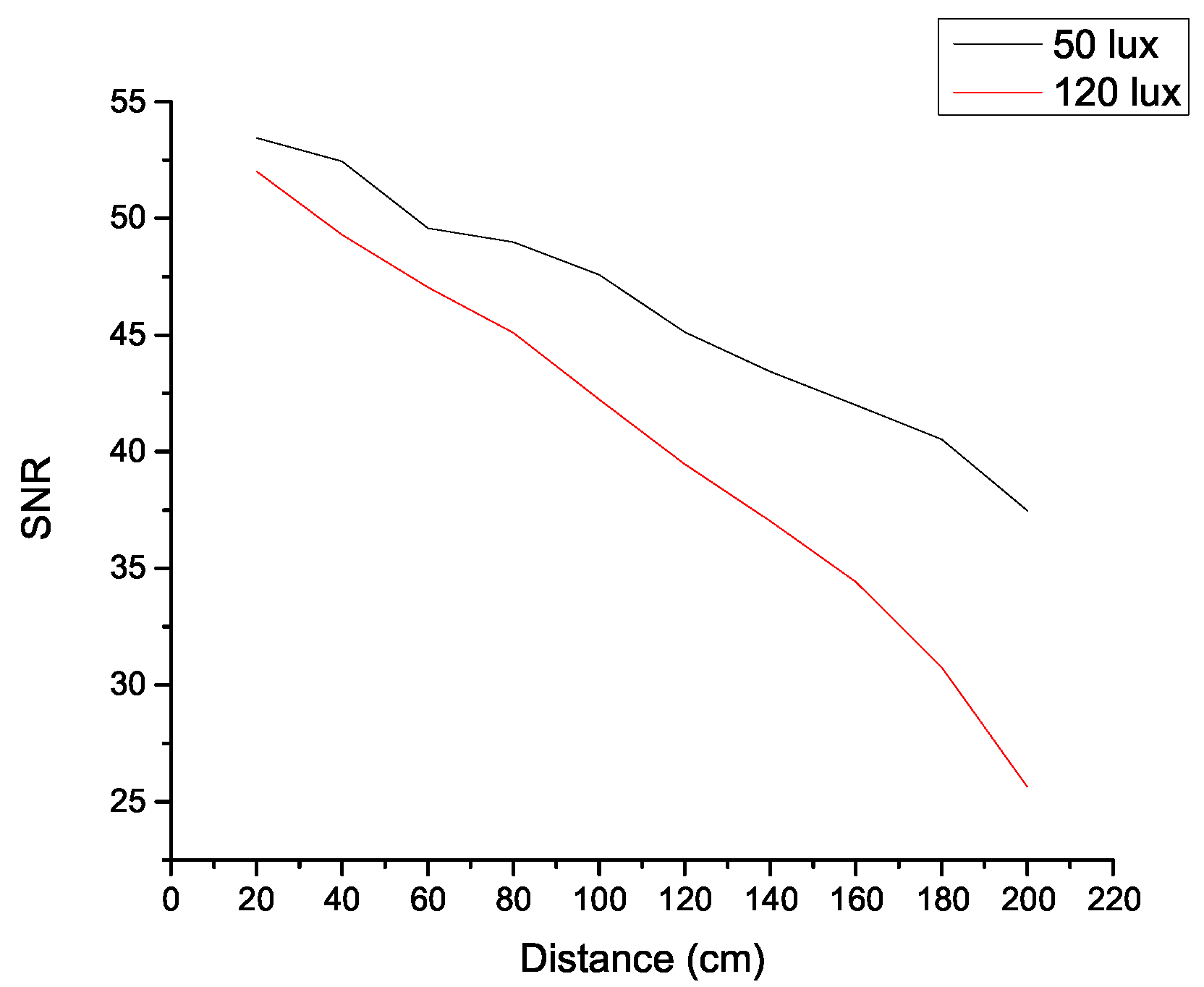
In addition to Signal-to-Noise Ratio(SNR) and Bit Error Ratio (BER), frames-per-bit [7] metric will also be used to evaluate the performance of the proposed modulation technique. SNR under various ambient lighting conditions and distances will be recorded. To measure SNR the ratio of overall pixel intensity of the image before transmission and during transmission will be estimated.
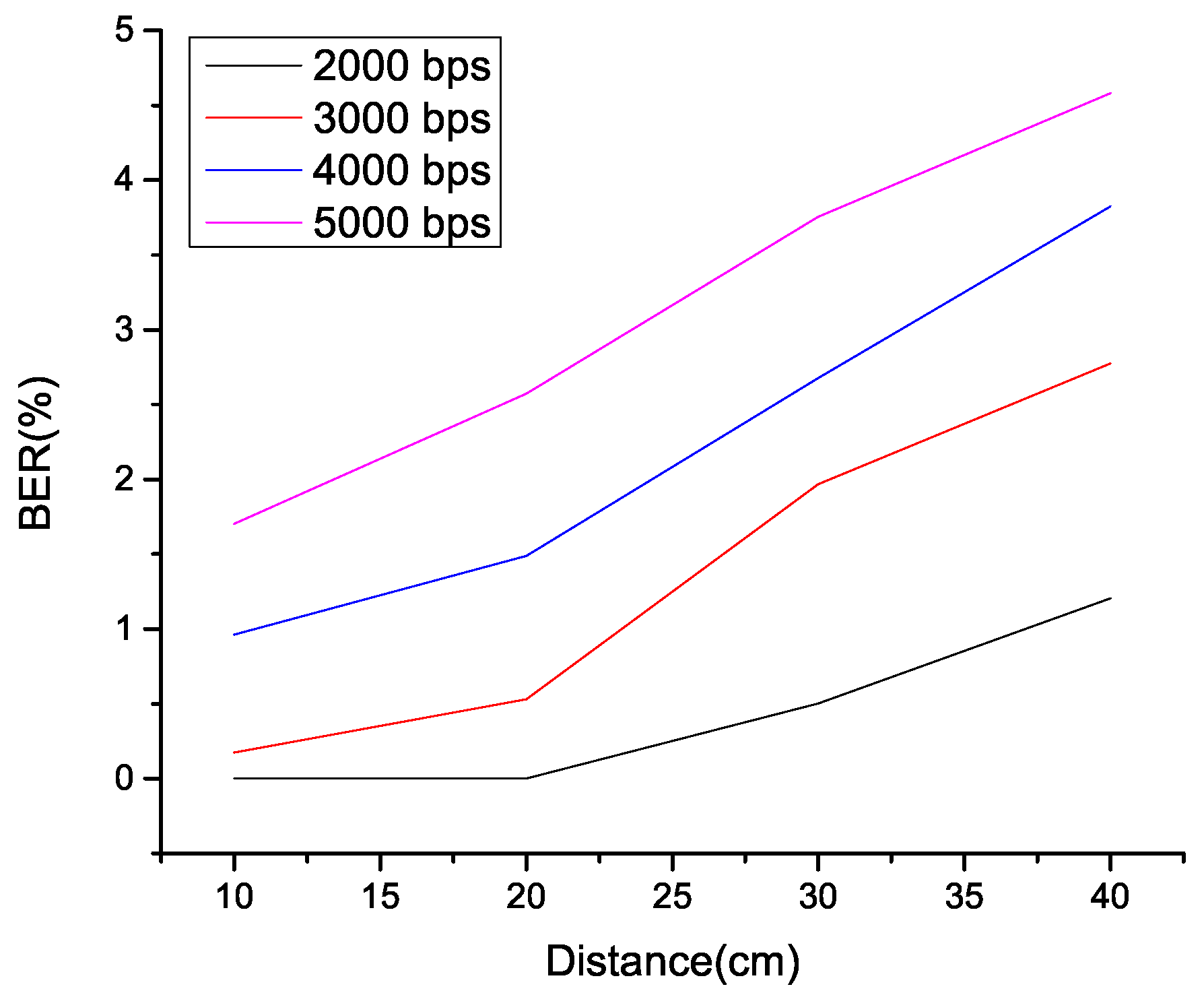
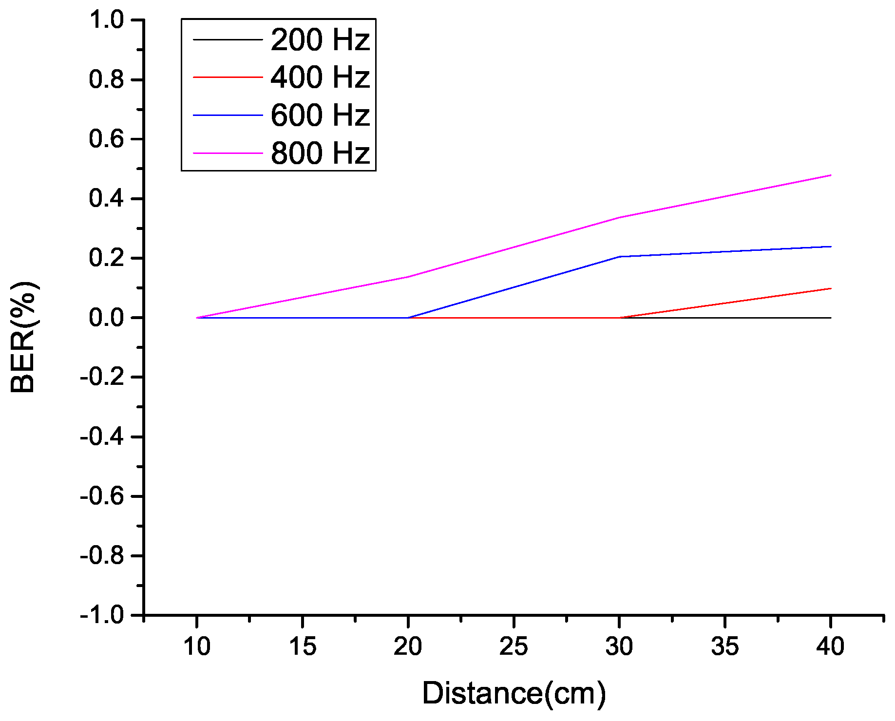
4. Design and Implementation

This section highlights the design and implementation of OOK, BFSOOK, and proposed HFSPDM. Discussion on each modulation is further divided into encoding and decoding steps. Since, all the demodulation techniques need to undergo common pre-processing, a standard preprocessing function is implemented as shown in Algorithm 1.
Algorithm 1 Common Image Preprocessing.
1:
Initialize a Buffer(size)
2:
function Preprocessing(image)
3:
    Convert image to grayscale
4:
    Enhance the contrast
5:
    Binarize the image
6:
    Dilute the image
7:
    Find dimensions of the brightest and largest blob
8:
    Mask the background
9:
    Crop the original image
10:
   Resize the cropped image based on found ROI
11:
   Grayscale, Enhance Contrast and Binarize the Cropped Image
12:
end function

4.1. OOK Modulation

OOK stands for On-Off Keying Modulation. In this modulation technique, logic bits, i.e., 1 and 0, are converted into on and off-duty cycles; this is one of the most popular techniques to provide data communication due to its ease of implementation [23]. Pulses in OOK modulation of a VLC system represent On and Off states of light. Thus, an OOK modulation can be achieved simply by converting the received data into on-off states of light. However, to achieve communication in the visible light spectrum, special care has to be taken to avoid flickering while performing data transmission. Thus, flickering issues can be tackled by having higher frequencies of On-Off cycles and using a suitable bit encoding technique like Manchester Encoding. However, in OCC-based communication, the cycles cannot be directly decoded because the frame rate of a standard camera is lower than the operational flicker-free frequency of the transmitter. Thus, the rolling shutter phenomenon is used to address the issue of high-frequency On-Off Cycles. The captured image is the result of serial activation of the array of micro photo-sensors of the camera. This allows the recording of transmitter states at different pixels at different times; which results in an image containing bands/stripes/rolls. The color of these stripes represents received bits. Dark stripes are for logic 0, and bright stripes are for logic 1. The width of dark and bright stripes will be equal, however, for manchester encoded bits there could be maximum two consecutive 0 s or two 1 s which will have twice the width of one 0 or one 1 bit. For example, if the width of dark and bright bands is 10 pixels individually, then manchester encoded bit pattern ‘100101’ will have widths like 10, 20, 10, 10, 10 pixels.

4.1.1. Encoding in OOK Modulation

The algorithmic implementation of OOK Modulation using a programmable board is as shown in Algorithm 2. Here the S e t u p function is used to initialize the LED-connected pins and a predefined test message. L o o p function is used to perform repetitive tasks, which includes sending the start bit pattern for synchronization before each byte is sent, followed by transmission of each bit of a byte. Furthermore, the S e n d function encodes the received bit into Manchester format and controls the LED states, respectively. For example, if the received bit is 1, post encoding, it becomes 0, 1, represented by Off states followed by On state of the LED. A minimum delay is decided, which should satisfy the flicker-free characteristic of light at the transmitter and the observable width of the stripe at the receiver. Depending on this value of x, the data rate and width of the observable stripes in the image are controlled. The size of transmitter and distance from the receiver also affects the number observable stripes.
Algorithm 2 OOK Modulation for Li-Fi Transmitter.
1:
function  Setup
2:
      Set pin mode to output for all the LED connected Pins
3:
      Set message
4:
end function
5:
function  Loop
6:
    Send(Start Bit Pattern)
7:
    for each byte in message do
8:
        for each bit in the byte do
9:
           Send(bit)
10:
        end for
11:
    end for
12:
end function
13:
function Send(a)                           ▹ Manchester encoding and LED Control
14:
    if a is 0  then
15:
        LED_On                                                                                           ▹ Signifies ‘1’
16:
        delay(x)
17:
        LED_Off                                                                                           ▹ Signifies ‘0’
18:
        delay(x)
19:
    else if a is 1 then
20:
        LED_Off                                                                                           ▹ Signifies ‘0’
21:
        delay(x)
22:
        LED_On                                                                                           ▹ Signifies ‘1’
23:
        delay(x)
24:
    end if
25:
end function

4.1.2. Decoding in OOK Modulation

Quick adaptive thresholding is used for decoding received signals. It calculates the moving average of grayscale values of the columnar sum of pixels from the cropped RoI. The algorithm consumes least memory for hardware implementation than other thresholding techniques such as Polynomial Fitting and Iterative Thresholding [24]. It is expressed mathematically as follows, where y i be the grayscale value of a pixel at point i and assume f s ( i ) be the sum of the values of the last s pixels at point i; hence it can be represented in Equation (1),
f s ( i ) = n = 0 s 1 y i n
A much faster way to calculate the weighted moving average is to subtract 1/s part of it and add the value of only the latest pixel instead of all s pixels; This is like emphasizing the grayscale values closer to the target value. Then the threshold in the quick adaptive thresholding is represented by Equation (2), where r is the adjustment ratio.
T = r n = 0 S 1 ( 1 1 S ) n y i n 1 n = 0 S 1 ( 1 1 S ) n
The process of demodulation of the received OOK signal at the receiver is as shown in Algorithm 3. This process is divided into three parts, namely image preprocessing, conversion of image to pulses, and finally the main orchestrator function. In M a i n function the video stream of an active Li-Fi transmitter is recorded which is further processed frames by frame. Each frame is passed to P r e p r o c e s s i n g function, which returns the RoI identified by using image processing techniques. The returned RoI is converted to a vector under the I m a g e T o P u l s e function. Obtained vector value is appended to a predefined buffer of arbitrary size. The process is repeated till the size of the buffer is full. Finally, data normalization is performed on the buffer, and each value in the buffer is compared with the threshold obtained by the sliding window average. Based on the outcome of the comparison, the bit value is decoded.
Algorithm 3 OOK Demodulation for OCC-LiFi Receiver.
1:
Initialize a Buffer(size)
2:
function ImageToPulse(CroppedImage)
3:
    Return colomwise sum
4:
end function
5:
function Main(video)
6:
    for each frame in the video do
7:
        Preprocessing(image)                                         ▹ As shown in Algorithm 1
8:
        ImageToPulse(CroppedImage)
9:
        Append the obtained vector to a buffer
10:
        if buffer size is full then
11:
           Normalize Values in buffer
12:
           for each value in the buffer do
13:
               if value > Sliding Window Average then
14:
                     decode bit as 1
15:
               else if value < Sliding Window Average then
16:
                     decode bit as 0
17:
               end if
18:
           end for
19:
        end if
20:
    end for
21:
end function

4.2. BFSOOK Modulation

Each bit is represented as one stripe in the captured image with OOK modulation. Although it provides a higher data rate but at the cost of increased sensitivity to noise. Additionally, the distance between transmitter and receiver is strictly related to the data rate. With a slight change in the distance, the number of observed stripes changes, and thus the decoded bits. Alternatively, in Frequency Shift OOK, the data is directly encoded in the form of frequencies of On-Off cycles. Therefore, by identifying the transmitting frequencies, the receiver can demodulate the signal. In Binary-FSOOK, two frequencies are used for representing logic 1 and 0 respectively.

4.2.1. Encoding in BFSOOK Modulation

The steps involved in encoding data under a BFSOOK Modulation technique are as shown in Algorithm 4. Here, the S e t u p function initializes parameters such as pins connected to the microcontroller, delay values, number of stripes, and test message. Delay1 and Delay2 is used for having different frequencies for On-Off Cycles, whereas, NumberOfStripes1 and NumberOfStripes2 are used for presetting observable stripes at the receiver for fixed distance of 20 cm. The function F r e q u e n c y accepts two parameters, namely as NumberOfStripes and Delay, based on which the frequency and number of iterations of On-Off Cycles are decided. S e n d function accepts binary values as input, depending upon which the corresponding frequency is selected. L o o p function is used to repetitively transmit start bit frequency followed by individual bits from the defined message.
Algorithm 4 BFSOOK Modulation for VLC Transmitter.
1:
function  Setup
2:
    Set pin mode to output for all the LED connected Pins
3:
    Set Delay1 and Delay2
4:
    Set NumberOfStripes1, NumberOfStripes2
5:
    Set message
6:
end function
7:
function Frequency(NumberOfStripes,Delay)
8:
    for i = 0 to NumberOfStripes do
9:
        LED_On
10:
        delay(Delay)
11:
        LED_Off
12:
        delay(Delay)
13:
    end for
14:
end function
15:
function Send(a)
16:
    if a is 0 then
17:
        Frequency(NumberOfStripes1,Delay1)
18:
    else if a is 1 then
19:
        Frequency(NumberOfStripes2,Delay2)
20:
    end if
21:
end function
22:
function  Loop
23:
    Send(Start Bit Pattern)
24:
    for each byte in message do
25:
        for each bit in the byte do
26:
           Send(bit)
27:
        end for
28:
    end for
29:
end function

4.2.2. Decoding in BFSOOK Modulation

BFSOOK modulation uses distinct OOK frequencies to transmit logic ones and logic zeros, respectively. Thus, the thresholding scheme used for BFSOOK has to distinguish between these two frequencies. This can be achieved in two ways, either by finding the number of stripes in the image or by finding the width of stripes. Equation (3), shows implementation of function to count the number of stripes from the given frame. Here, N S t r i p e s represent the number of Stripes, C is the set of values obtained after performing column-wise sum, normalization and binarization. Thus C consists only of binary values, and m is the length of the vector C.
N S t r i p e s = 1 m 1 ( C i C i + 1 ) 2 2
Consider for a sample binary bit stream of b 1 , b 2 , b 3 , b 4 , b 5 , b 6 , b 7 represented by 0, 0, 1, 1, 1, 0, 0. Here, consecutive 1 s represent a white stripe. After performing ( C i C i + 1 ) 2 from b 1 to b 7 the output generated is 0, 1, 0, 0, 0, 1, 0. After performing summation over it we get 2 which represent edges of the stripe and by dividing it by 2 we get 1 i.e., the 1 white stripe is detected.
For detecting the width of stripes, Equations (4) and (5) is used. Here, c o u n t i maintains the sum of consecutive non-zero values. Thus, bit values from b 1 b 7 are represented as 0, 0, 1, 2, 3, 0, 0 respectively. By finding the maximum of all the values, the maximum width of the stripe in the frame is estimated.
c o u n t i = c o u n t i 1 + 1 , i f m a x > c o u n t i 0 , otherwise
m a x = m a x i f m a x > c o u n t i c o u n t i o t h e r w i s e
Algorithm 5 shows algorithmic implementation of BFSOOK receiver based on discussed equations. Post thresholding the value obtained is added to a buffer. Once the size of this buffer is full, data normalization is performed. Each value from the buffer is then compared with the obtained threshold from the previous function, and the respective binary value is decoded.
Algorithm 5 BFSOOK Demodulation for VLC-OCC Receiver.
1:
Initialize a Buffer(size)
2:
function CountEdges(CroppedImage)
3:
    Perform Edge detection
4:
    Return number of edges detected
5:
end function
6:
function CountWidth(CroppedImage)
7:
       Convert to a Row Vector using Columnwise Sum
8:
       Normalize the Row
9:
       Binarize the row
10:
      Find length non-zero sub-sequences
11:
      Return average width
12:
end function
13:
function Main(video)
14:
    for each frame in the video do
15:
        Preprocessing(image)                      ▹ As shown in Algorithm 1
16:
        CountEdges(CroppedImage)/CountWidth(CroppedImage)
17:
        Append the obtained vector to a buffer
18:
        if buffer size is full then
19:
           Normalize Values in buffer
20:
           for each value in the buffer do
21:
               if value > Sliding Window Average then
22:
                     decode bit as 1
23:
               else if value < Sliding Window Average then
24:
                     decode bit as 0
25:
               end if
26:
           end for
27:
        end if
28:
    end for
29:
end function

4.3. Proposed HFSPDM Modulation

The proposed Hybrid Frequency Shift-Pulse Duration Modulation technique is discussed in this section. Figure 6 shows the arrangement of frequencies to distinguish data pattern from start/stop bit pattern. Here, F 1 , F 2 , and F 3 represent three distinct frequencies that satisfy specific relations. For example, F 1 = 4 × F 3 , F 1 = 2 × F 2 and F 2 = 2 × F 3 . Here, F 1 represents start bit pattern frequency. Identification of this frequency enables us to estimate the next frames. The data bit pattern is divided into two subparts to map with the desired bit pattern. The combination of two frequencies represents four 2-bit patterns such as 00, 10, 01, and 11. The data bit pattern is enclosed within two consecutive start bit patterns. Table 1 shows the mapping of four 2-bit patterns to their respective frequencies, duty cycles, and pulse shape. The modulation method is a Hybrid of FSK and PDM since frequency duration is used for decoding bits.

4.3.1. Encoding in HFS-PDM Modulation

The steps involved in the encoding of data bits using HFSPDM is as shown in Algorithm 6. The S e t u p function sets all the required variables and pins connected to the programmable board. The working of F r e q u e n c y and S e n d Function is the same as explained in BFSOOK Modulation (4.2.1) except for a minor change with respect number of bits sent. In the proposed technique, 2 bits are passed to the S e n d function thus, the S e n d function has to handle four states. Additionally since, the start bit is represented by a different frequency, the S e n d function has to also handle the fifth case of the start bit pattern. For, the purpose of convenience each bit pair is divided into four calls to the F r e q u e n c y function. thus, depending upon the bit pair, the corresponding frequency duration can be controlled. For example, if bit pair is 00, then F 2 frequency i.e., F r e q u e n c y ( N u m O f S t r i p e s 2 , D e l a y 2 ) will be called 4 times. Whereas, if the bit pair is 01, Frequency F 2 will be called 3 times followed by Frequency F 3 i.e., F r e q u e n c y ( N u m O f S t r i p e s 3 , D e l a y 3 ) which will be called only once. Typically, the encoded frequencies follow the Nyquist sampling theorem, and the relation between the number of stripes, delay, and frame rate is provided as follows:
B r = F r 2
D 1 = 1 2 × ( ( ( 1 / B r ) × 10 6 ) / N l 1 )
D 2 = 1 2 × ( ( ( 1 / B r ) × 10 6 ) / ( 2 × N l 1 ) )
F 1 = 1 D 1 , ( w h e r e F 1 > F f f )
F 2 = 1 D 2 , ( w h e r e F 2 > F f f )
Here, F r is Camera Frame Rate, B r is bit encoding rate, N l 1 is number of stripes expected, D 1 and D 2 is the delay between On-Off cycle, resulting into frequency F 1 and F 2 . These frequencies represent logic 1 and 0. Special care should be taken while assigning the number of lines as it affects the frequency and detection of stripes. The frequency should be more than the minimum flicker-free frequency ( F f f ), i.e., 200 Hz.
Algorithm 6 HFSPDM for Li-Fi Transmitter.
1:
function Send(a)
2:
    switch a do
3:
        case 00
4:
               4 times Frequency(NumOfStripes2,Delay2)
5:
        case 10
6:
               Frequency(NumOfStripes2,Delay2)
7:
               3 times Frequency(NumOfStripes3,Delay3)
8:
        case 01
9:
               3 times Frequency(NumOfStripes2,Delay2)
10:
               Frequency(NumOfStripes3,Delay3)
11:
        case 11
12:
               4 times Frequency(NumOfStripes3,Delay3)
13:
        case  S t a r t B i t
14:
               Frequency(NumOfStripes1,Delay1)
15:
end function

4.3.2. Decoding in HFS-PDM Modulation

Decoding of HFSPDM Modulated signal requires two thresholding steps. First thresholding is performed to identify the frequencies, while the second thresholding is performed to identify the duration of frequencies. The first level of thresholding is performed similar to BFSOOK as discussed in Section 4.2.2, which provides the largest stripe width from each frames. The widest stripe from sample frames should be four times the width of the smallest stripe due to the preset relation between frequencies. However, as the practical system is prone to external noise, an error margin of 10% of the widest stripe is set. Thus, the relation between the widths of different frequencies is given as follows, where W1, W2, and W3 are widths of stripes in the frames for frequencies F 1 , F 2 , and F 3 , respectively.
W 3 = 4 × W 1 ± W 1 10
Stripe width of second frequency can be estimated from W3 and W1 as shown in Equation (12)
W 2 = W 3 2 ± W 1 10
After finding frequency from the frames, second thresholding is applied based on Percentage Frequency Frame Ratio(PFFR). In this method, the percentage occurrence of any frequency frame out off F 2 and F 3 can be considered. For example Equation (13) shows P F 2 as percentage of F 2 frequency frames. Where, T F 2 is total number of frames between successive start frames containing F 2 frequency and N F r a m e s is total number of frame between successive start frames.
P F 2 = T F 2 N F r a m e s × 100
The algorithmic implementation of HFSPDM is as shown in Algorithm 7. The duration of frequencies should be more than twice the frame rate of camera for sampling. Here, assuming pre-processing is performed, a sample set of stripe widths from the video stream is created. The frames can be identified in F 1 , F 2 , and F 3 frequency frames from the obtained widths. Finally, the bit pairs are decoded by counting the number of F 2 and F 3 frequency frames and comparing it with the threshold values. Here two boolean flags are used to track start bit frequency F 1 and count the number of F 2 and F 3 frequency frames. F r 2 and F r 3 consist of the count of respective frequency frames and percentage of F 2 or F 3 frequency is estimated. The obtained percentage is then used to decode the bit pair using percentage mapping applied during encoding.
Algorithm 7 HFSPDM Demodulation for VLC-OCC Receiver.
1:
function CountFrequencyFrame(CroppedImage)
2:
    W=CountWidth(CroppedImage)
3:
    if W==F1 and Flag1==0 and Flag2=0 then
4:
        Set Flag1=1
5:
    else if W==F2 and Flag1==1 then
6:
        Set Flag2=1
7:
        Increment Counter for F2
8:
    else if W==F3 and Flag1==1 then
9:
        Set Flag2=1
10:
        Increment Counter for F3
11:
    else if W==F1 and Flag1==1 and Flag2==1 then
12:
        Set Flag1=0
13:
        Set Flag2=0
14:
        Return Count of F2 and F3 Frequency containing frames
15:
    end if
16:
end function
17:
function Main(video)
18:
    for each frame in the video do
19:
        Preprocessing(image)                          ▹ As shown in Algorithm 1
20:
        CountWidth(CroppedImage)
21:
        Append the obtained value in a buffer
22:
        if buffer size is full then
23:
           F1=min(buffer)
24:
           F3=4×F1+F1/10
25:
           F2=F3/2+F1/10
26:
        end if
27:
    end for
28:
    for each frame in the video do
29:
        Fr2,Fr3=CountFrequencyFrames(CroppedImage)
30:
        Compare with the threshold value
31:
        Decode bit pair
32:
    end for
33:
end function

5. Experimental Setup

In this section, the hardware and software details used for the implementation of a testbed and camera parameters used for testing are discussed.

5.1. Testbed Setup

A circuit diagram for controlling LED as Li-Fi Transmitter is shown in Figure 7a. For building the VLC transmitter testbed an Arduino Mirco programmable board is used. Three off-the-shelf multi-color LEDs are connected to the board. To avoid direct exposure to these bright lights and to have a well-defined shape transmitter a simple diffuser is used. Thus with a diffuser, the radius of the transmitter is 3 cm. Figure 7 shows the implemented VLC Transmitter under different conditions such as (a) circuit diagram, (b) without a diffuser, (c) with a diffuser, and (d) operational. Each modulation technique is tested for a variable distance between transmitter and receiver and at different frequencies. Figure 8 shows the experimental setup for the performance evaluation of the proposed technique.
The SNR was measured by keeping the brightness, contrast and exposure parameters constant under different ambient light values i.e., 50 lux and 120 lux. Equation (14) gives sum of pixel intensities of the image where, P i j is pixel intensity of grayscaled image at position i, j and Z i is an image frame. As shown in Equation (15) A i is image frame containing active transmitter while B i is image frame containing inactive transmitter. The average pixel intensity observed with transmitter ‘on’ was considered as Signal Power while the average pixel intensity of frame with transmitter ‘off’ was considered as Noise Power to estimate SNR.
Z i = j = 1 y i = 1 x P i j
S N R d B = 10 × log 1 n i = 0 n 1 | A i | 2 1 n i = 0 n 1 | B i | 2

5.2. Camera Parameters

For the experimental analysis of the proposed method, a video feed from an Oppo A3S android phone camera is taken, and an application named “Open Camera” is used to adjust the exposure and frame rate. Other parameters are as shown in Table 2:

6. Results

This section discusses results obtained from each experimental evaluation of each modulation technique.
Figure 9 shows that as the distance and ambient light intensity increases the SNR value decreases. Further experiments were conducted by keeping the ambient light intensity between 50–60 lux as it provided better SNR. Stress pattern of alternate 0 and 1 is used for finding BER.

6.1. Results for OOK

The first experiment was to analyze the effect of OOK modulation frequency concerning distance. The number of stripes detected from the frame is the evaluation parameter. For each frequency and distance, an average of 5 tests is considered. As shown in Figure 10, it is observed that for the shorter distance, the number of stripes detected is more and drastically decreases with the increase in the distance. It is majorly because of the decrease in the RoI region while stripe width stays constant. Thus, an optimal trade-off between frequency, distance, and size of light aperture is required. The number of detectable stripes in OOK modulation is directly proportional to the data rate.
The other experiment was to analyze the relation between stripe width and distance. As shown in Figure 11, it was observed that stripe width is inversely proportional to frequency. However, it was also observed that there was no significant visible stripe for very low frequencies and greater distances; this is due to the size of the aperture and the number of pixels it occupied in the image/video. Here, the stripe width remains constant, but identification of RoI based on the implemented pre-processing techniques fails as the distance increases; this is majorly due to the absence of the brightest blob in the image as the transmitter appears to be overlapped by a dark stripe. Also, the decrease in the size of stripe width is observed to follow the elliptic curve, where the curve reaches its minimum at the frequency of 2000 Hz for a fixed distance of 20 cm and starts ascending again. This behavior was observed due to the phenomenon of pixel spreading which results in stripes with smaller widths spreading and causing boundary detection error.
The steps involved in pre-processing and identification of the number of stripes and stripe width are shown in Figure 12. Here, two cases with the same OOK frequency but varying distances are shown. The number of stripes detected is dependent on the distance, whereas the width of the stripe remains almost identical. It was an important observation as it defined a reliable feature to identify frequencies in BFSOOK.
Figure 13, shows the comparison between various window sizes for quick adaptive thresholding. It is observed via trial and error that for smaller window sizes threshold is more adaptive. Thus, by keeping the window size to 10, experiments to test the BER of OOK system are conducted. The evaluation is performed based on the percentage of wrongly received bits out of 2048 bits. As shown in Figure 14, it was observed that for lower bit rate, the rate of change in BER concerning distance is comparatively slower than higher frequencies; this is because detection of LED State under lower frequency is better compared to a higher frequency. Thus, in OOK modulation, as the number of bits represented per frame is proportional to the distance between transmitter and receiver, the accuracy decreases at a higher data rate due to frame loss.

6.2. Results for BFSOOK

Based on the experiments conducted for OOK, it was evident that for the classification of frequencies the stripes’ width is a better deciding factor than the number of stripes. Thus, the max of widths per frame is used to identify the frequency and thus determine the bit.
Figure 15 shows max widths of subsequent frequencies used for representing logic 0 and 1. 500 Hz and 1000 Hz are the two frequencies used, and the distance of 20 cm is kept constant for testing the thresholding method. Figure 15 also shows that a sliding window size of 5 provided more adaptive thresholding for the determination of bits. Further, by keeping window size constant, the accuracy of the modulation scheme is tested. The frequencies selected follow F 2 = 2 × F 1 , to enable better classification, where F 1 and F 2 are frequencies for bit 0 and 1.
Figure 16 shows the BER in percentage considering 2048 bits at varying distances. Here, F 1 frequency is used for representation. It is observed from the result that the BER(%) is 0% for F 1 = 200 Hz viz. F 2 = 400 Hz. This is because the difference between the widths for F 1 and F 2 frequency is prominent and thus easy to decode. Whereas, due to the elliptic relation between width and frequency, as the frequency increases, there is a decrease in the difference between widths, making bit estimation more prone to errors resulting in an increase in BER.
BFSOOK is more robust than OOK as the technique is inherently asynchronous and independent of distance. This modulation method provides better accuracy than OOK, even for a distance up to 40 cm considering a smaller transmitter. However, the obtained data rate is lower than OOK as the number of frames required to decode the bit is higher.

6.3. Results for HFSPDM

The frequencies used for HFSPDM follow relation of F 3 = 2 × F 2 = 4 × F 1 . Figure 17 shows the obtained signal in terms of column sum for each frame. In order to provide ease of understanding and representation, the duration for each frequency is extended to multiple frames, and a repeated sequence of four 2-bit pairs is transmitted. A sliding window of size 5 is used to smoothen the obtained signal, which is then further processed to identify the frequencies. Figure 18 shows the filtered signal. Three levels can be identified from the signal; the lowermost level shows frames with stripe widths of 22 pixels approximately, the second level at a width of around 45 pixels, and the third level at a width of 80 pixels approximately. Each of these levels represents three distinct frequencies. The number of frames containing frequencies 2 and 3 between successive frequency 1 frames is identified for decoding. The final bit pair is decoded based on the percentage of frequency 2 frames. Figure 18 shows repeated decoding of bit pattern 00, 01, 10 and 11.
An overall comparison of all three implemented techniques, i.e., OOK, BFSOOK, and HFSPDM, is shown in Figure 19. The best results for each technique are compared. In general, bit rate should be kept constant for comparing BERs. However, OOK operates at very high bit rates compared to BFSOOK and HFSPDM, thus, the ratio of BER to bit rate is used as metrics to evaluate. Hence, the lower the value better will be the performance of the technique. It was observed that BFSOOK provided consistent BER/bps close to 0 for frequency 200 Hz while our proposed HFSPDM technique has shown BER/bps closer to 0.04. However, it was also observed that in HFSPDM, the number of frames required to transmit the same amount of data as that in BFSOOK was considerably lesser but more than OOK. This is because HFSPDM represents 2 bits per 5 frames on average, whereas BFSOOK represents 1 bit per 3 frames. The bit to frame ratio is much higher in OOK which is of order 20 bits-per-frame; however, HFSPDM gives better BER for longer distances than OOK based on standard implementation using low-cost devices. Table 3 shows the relative performance of HFSPDM in comparison with OOK and BFSOOK.

7. Conclusions

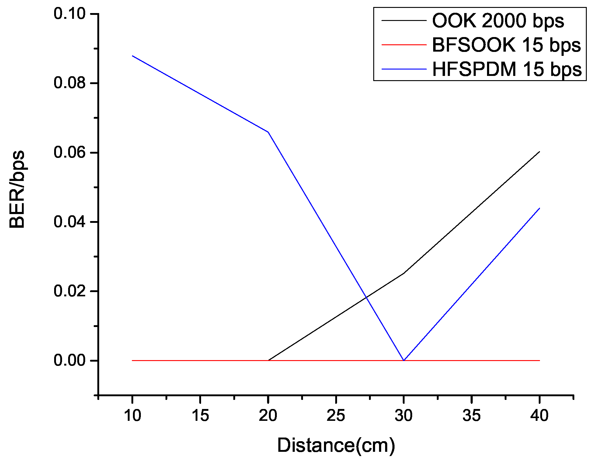
In this paper, a novel technique called Hybrid Frequency Shift-Pulse Width Modulation (HFSPDM) was proposed and implemented on an in-house Li-Fi testbed. The other two modulation techniques, OOK and BFSOOK, were implemented on the same testbed to compare their performances. The best results for each technique were compared. It was observed that BFSOOK provided consistent BER/bps of close to 0 for a frequency 200 Hz while our proposed HFSPDM technique has shown BER/bps closer to 0.04. It was also observed that in HFSPDM, the number of frames required to transmit the same amount of data as that in BFSOOK was considerably lesser but more than OOK; this is due to the fact that HFSPDM represents, on average, 2 bits per 5 frames, whereas BFSOOK represents 1 bit per 3 frames. The bit-to-frame ratio is higher in terms of OOK; however, HFSPDM gives better BER for longer distances than OOK as OOK is more sensitive to noise. Thus, it can be concluded that HFSPDM can be used in OCC applications that require low computation and high accuracy for comparatively longer distances.

Author Contributions

Conceptualization; methodology, S.S.; validation, G.V.; formal analysis, S.S.; investigation, S.S.; resources, S.S.; writing—original draft preparation, S.S.; writing—review and editing, S.S. and G.V.; supervision, G.V.; project administration, G.V. All authors have read and agreed to the published version of the manuscript.

Funding

This research received no external funding.

Institutional Review Board Statement

Not applicable.

Informed Consent Statement

Not applicable.

Data Availability Statement

The code and relevant data is available at the following link https://github.com/SanketSalviNITK/LiFiPrototype.git (accessed on 27 June 2022).

Conflicts of Interest

The authors declare no conflict of interest.

Abbreviations

The following abbreviations are used in this manuscript:
LEDLight Emitting Diode
RFRadio Frequency
Li-FiLight Fidelity
VLCVisible Light Communication
OCCOptical Camera Communication
OOKOn Off Keying
PDMPulse Duration Modulation
FSOOKFrequency Shift OOK
BFSOOKBinary FSOOK
SNRSignal to Noise Ratio
BERBit Error Ratio
bpsbits per second
HFSPDMHybrid Frequency Shift Pulse Duration Modulation

References

  1. Nada, M.; Yamada, Y.; Matsuzaki, H. Responsivity-Bandwidth Limit of Avalanche Photodiodes: Toward Future Ethernet Systems. IEEE J. Sel. Top. Quantum Electron. 2018, 24, 1–11. [Google Scholar] [CrossRef]
  2. Shulyak, V.; Hayat, M.M.; Ng, J.S. Sensitivity Calculations of High-Speed Optical Receivers Based on Electron-APDs. J. Light. Technol. 2020, 38, 989–995. [Google Scholar] [CrossRef] [Green Version]
  3. Sadat, H.; Abaza, M.; Mansour, A.; Alfalou, A. A Survey of NOMA for VLC Systems: Research Challenges and Future Trends. Sensors 2022, 22, 1395. [Google Scholar] [CrossRef]
  4. Liang, X.; Yuan, M.; Wang, J.; Ding, Z.; Jiang, M.; Zhao, C. Constellation Design Enhancement for Color-Shift Keying Modulation of Quadrichromatic LEDs in Visible Light Communications. J. Light. Technol. 2017, 35, 3650–3663. [Google Scholar] [CrossRef]
  5. Singh, R.; O’Farrell, T.; David, J.P.R. Higher Order Colour Shift Keying Modulation Formats for Visible Light Communications. In Proceedings of the 2015 IEEE 81st Vehicular Technology Conference (VTC Spring), Glasgow, UK, 11–14 May 2015; pp. 1–5. [Google Scholar] [CrossRef]
  6. Aguiar-Castillo, L.; Guerra, V.; Rufo, J.; Rabadan, J.; Perez-Jimenez, R. Survey on Optical Wireless Communications-Based Services Applied to the Tourism Industry: Potentials and Challenges. Sensors 2021, 21, 6282. [Google Scholar] [CrossRef]
  7. He, J.; Zhou, Y.; Deng, R.; Shi, J.; He, J.; Jiang, Z.; Tang, Q. Efficient Sampling Scheme Based on Length Estimation for Optical Camera Communication. IEEE Photonics Technol. Lett. 2019, 31, 841–844. [Google Scholar] [CrossRef]
  8. Shi, J.; He, J.; He, J.; Jiang, Z.; Zhou, Y.; Xiao, Y. Enabling user mobility for optical camera communication using mobile phone. Opt. Express 2018, 26, 21762–21767. [Google Scholar] [CrossRef]
  9. Nguyen, H.; Thieu, M.D.; Pham, T.L.; Nguyen, H.; Jang, Y.M. The Impact of Camera Parameters on Optical Camera Communication. In Proceedings of the 2019 International Conference on Artificial Intelligence in Information and Communication (ICAIIC), Okinawa, Japan, 11–13 February 2019; pp. 526–529. [Google Scholar] [CrossRef]
  10. Teli, S.R.; Zvanovec, S.; Ghassemlooy, Z. The first tests of smartphone camera exposure effect on optical camera communication links. In Proceedings of the 2019 15th International Conference on Telecommunications (ConTEL), Graz, Austria, 3–5 July 2019; pp. 1–6. [Google Scholar] [CrossRef] [Green Version]
  11. Lee, H.Y.; Lin, H.M.; Wei, Y.L.; Wu, H.I.; Tsai, H.M.; Lin, K.C.J. RollingLight: Enabling Line-of-Sight Light-to-Camera Communications. In Proceedings of the 13th Annual International Conference on Mobile Systems, Applications, and Services, MobiSys’ 15, Florence, Italy, 18–22 May 2015; pp. 167–180. [Google Scholar] [CrossRef]
  12. Li, Z.; Zhang, Z.; Yuan, Q.; Qiao, Y.; Liao, K.; Yu, H. Digital image processing in led visible light communications using mobile phone camera. In Proceedings of the 2016 IEEE International Conference on Network Infrastructure and Digital Content (IC-NIDC), Beijing, China, 23–25 September 2016; pp. 239–243. [Google Scholar] [CrossRef]
  13. Kim, B.; Park, H.; Kim, Y.; Yeom, I. Decoding method comparisons in Light-to-Camera communication. In Proceedings of the 2017 International Conference on Information Networking (ICOIN), Da Nang, Vietnam, 11–13 January 2017; pp. 80–82. [Google Scholar] [CrossRef]
  14. Rajagopal, N.; Lazik, P.; Rowe, A. Hybrid Visible Light Communication for Cameras and Low-Power Embedded Devices. In Proceedings of the 1st ACM MobiCom Workshop on Visible Light Communication Systems, MobiCom’14, Maui, HI, USA, 7 September 2014; pp. 33–38. [Google Scholar] [CrossRef]
  15. Le, N.; Nguyen, T.; Jang, Y.M. Frequency shift on-off keying for optical camera communication. In Proceedings of the 2014 Sixth International Conference on Ubiquitous and Future Networks (ICUFN), Shanghai, China, 8–11 July 2014; pp. 22–25. [Google Scholar] [CrossRef]
  16. Van Thang, N.; Le, N.T.; Vu, T.L.; Thieu, M.D.; Jang, Y.M. An Implementation of Binary Frequency Shift On-Off Keying Modulation for Optical Camera Communication. In Proceedings of the 2018 Tenth International Conference on Ubiquitous and Future Networks (ICUFN), Prague, Czech Republic, 3–6 July 2018; pp. 121–125. [Google Scholar] [CrossRef]
  17. Roberts, R.D. Undersampled frequency shift ON-OFF keying (UFSOOK) for camera communications (CamCom). In Proceedings of the 2013 22nd Wireless and Optical Communication Conference, Chongqing, China, 16–18 May 2013; pp. 645–648. [Google Scholar] [CrossRef]
  18. Deng, R.; Liu, L.; Shao, Y.; Chen, L. 2D-Constellation-Assisted CSK transmission over OCC system under low-level illuminance. In Proceedings of the 2019 24th OptoElectronics and Communications Conference (OECC) and 2019 International Conference on Photonics in Switching and Computing (PSC), Fukuoka, Japan, 7–11 July 2019; pp. 1–3. [Google Scholar] [CrossRef]
  19. Chen, H.; Wen, S.; Wang, X.; Liang, M.; Li, M.; Li, Q.; Liu, Y. Color-Shift Keying for Optical Camera Communication Using a Rolling Shutter Mode. IEEE Photonics J. 2019, 11, 1–8. [Google Scholar] [CrossRef]
  20. Hu, P.; Pathak, P.; Zhang, H.; Yang, Z.; Mohapatra, P. High Speed LED-to-Camera Communication using Color Shift Keying with Flicker Mitigation. IEEE Trans. Mob. Comput. 2019, 19, 1603–1617. [Google Scholar] [CrossRef] [Green Version]
  21. Hasan, M.K.; Chowdhury, M.Z.; Shahjalal, M.; Nguyen, V.T.; Jang, Y.M. Performance Analysis and Improvement of Optical Camera Communication. Appl. Sci. 2018, 8, 2527. [Google Scholar] [CrossRef] [Green Version]
  22. Chavez-Burbano, P.; Rabadan, J.; Guerra, V.; Perez-Jimenez, R. Flickering-Free Distance-Independent Modulation Scheme for OCC. Electronics 2021, 10, 1103. [Google Scholar] [CrossRef]
  23. Kennedy, H.; Bodnar, R.; Lee, T.; Redman-White, W. 28.4 A High-Q Resonant Inductive Link Transmit Modulator/Driver for Enhanced Power and FSK/PSK Data Transfer Using Adaptive-Predictive Phase-Continuous Switching Fractional-Capacitance Tuning. In Proceedings of the 2019 IEEE International Solid- State Circuits Conference—(ISSCC), San Francisco, CA, USA, 17–21 February 2019; pp. 444–446. [CrossRef] [Green Version]
  24. Liu, Y.; Chow, C.W.; Liang, K.; Chen, H.Y.; Hsu, C.W.; Chen, C.Y.; Chen, S.H. Comparison of thresholding schemes for visible light communication using mobile-phone image sensor. Opt. Express 2016, 24, 1973–1978. [Google Scholar] [CrossRef] [PubMed]
Figure 1. VLC enabled Lamp.
Computation 10 00110 g001
Figure 2. The schematic block diagram of an OCC system.
Computation 10 00110 g002
Figure 3. Modulation Patterns.
Computation 10 00110 g003
Figure 4. Rolling Shutter Effect.
Computation 10 00110 g004
Figure 5. Decoding Steps.
Computation 10 00110 g005
Figure 6. Sample Frame Format in terms of Frequency for HFSPDM.
Computation 10 00110 g006
Figure 7. Li-Fi Transmitter. (a) Transmitter Circuit. (b) VLC Transmitter. (c) VLC Transmitter with Diffuser. (d) Operational VLC Transmitter.
Computation 10 00110 g007
Figure 8. Experimental Setup with Transmitter and Receiver distances as 20 cm and 40 cm from left respectively.
Computation 10 00110 g008
Figure 9. SNR vs. Distance vs. Ambient Light.
Computation 10 00110 g009
Figure 10. OOK Modulation Distance vs. Detectable Stripes for various frequencies.
Computation 10 00110 g010
Figure 11. OOK Modulation Frequency vs. Stripe Width.
Computation 10 00110 g011
Figure 12. Number of Lines vs. width vs. distance.
Computation 10 00110 g012
Figure 13. OOK Sliding Window Thresholding.
Computation 10 00110 g013
Figure 14. OOK BER vs. Distance.
Computation 10 00110 g014
Figure 15. BFSOOK max widths per Frame and Thresholding Window.
Computation 10 00110 g015
Figure 16. BFSOOK BER vs. Distance.
Computation 10 00110 g016
Figure 17. HFSPDM Signal.
Computation 10 00110 g017
Figure 18. Filtered HFSPDM Signal.
Computation 10 00110 g018
Figure 19. Accuracy Comparison of OOK, BFSOOK and HFSPDM.
Computation 10 00110 g019
Table 1. HFSPDM Frequency Mapping Table.
Data BitFrequency DistributionPulse Shape
00F2(100%) + F3(0%) Computation 10 00110 i001
01F2(75%) + F3(25%) Computation 10 00110 i002
10F2(25%) + F3(75%) Computation 10 00110 i003
11F2(0%) + F3(100%) Computation 10 00110 i004
Table 2. Camera Parameter.
ParameterValueParameterValue
ExposureISO3200Contrast100
Frame Rate30FPSBrightness100
Resolution160 × 96Ambient Light50–120 lux
Table 3. HFSPDM vs. OOK vs. BFSOOK.
Modulation TechniqueBER/bpsNo. of Frames per BitDistance (cm)
OOK0.060.05<20
BFSOOK 03>20
HFSPDM0.042.5>20
Publisher’s Note: MDPI stays neutral with regard to jurisdictional claims in published maps and institutional affiliations.

