Article

Parallelization of Runge–Kutta Methods for Hardware Implementation

1
Department of Computer-Aided Design, Saint Petersburg Electrotechnical University “LETI”, 5, Professora Popova St., Saint Petersburg 197376, Russia
2
Department of Automation and Control Processes, Saint Petersburg Electrotechnical University ”LETI”, 5, Professora Popova St., Saint Petersburg 197376, Russia
3
Department of Computer Systems and Networks, Saint-Petersburg State University of Aerospace Instrumentation, 67, Bolshaya Morskaya St., Saint Petersburg 190000, Russia
*
Author to whom correspondence should be addressed.
Computation 2022, 10(12), 215; https://doi.org/10.3390/computation10120215
Submission received: 22 October 2022 / Revised: 2 December 2022 / Accepted: 3 December 2022 / Published: 7 December 2022
(This article belongs to the Special Issue Mathematical Modeling and Study of Nonlinear Dynamic Processes)

Abstract

:
Parallel numerical integration is a valuable tool used in many applications requiring high-performance numerical solvers, which is of great interest nowadays due to the increasing difficulty and complexity in differential problems. One of the possible approaches to increase the efficiency of ODE solvers is to parallelize recurrent numerical methods, making them more suitable for execution in hardware with natural parallelism, e.g., field-programmable gate arrays (FPGAs) or graphical processing units (GPUs). Some of the simplest and most popular ODE solvers are explicit Runge–Kutta methods. Despite the high implementability and overall simplicity of the Runge–Kutta schemes, recurrent algorithms remain weakly suitable for execution in parallel computers. In this paper, we propose an approach for parallelizing classical explicit Runge–Kutta methods to construct efficient ODE solvers with pipeline architecture. A novel technique to obtain parallel finite-difference models based on Runge–Kutta integration is described. Three test initial value problems are considered to evaluate the properties of the obtained solvers. It is shown that the truncation error of the parallelized Runge–Kutta method does not significantly change after its known recurrent version. A possible speed up in calculations is estimated using Amdahl’s law and is approximately 2.5–3-times. Block diagrams of fixed-point parallel ODE solvers suitable for hardware implementation on FPGA are given.

1. Introduction

Simulating continuous systems in discrete computers usually requires the numerical solution of ordinary differential equations (ODEs), which is usually performed using numerical integration methods [1,2,3,4]. Software implementing numerical integration methods is called an ODE solver. One of the critical characteristics of the ODE solver is its computational efficiency, usually determined as the dependence between the precision of the achieved solution and the time taken to obtain it [5]. Explicit Runge–Kutta (RK) methods are among the most popular solvers and belong to the broad class of single-step integration. They possess satisfactory numerical stability and high computational efficiency, being a reliable and straightforward tool for simulation software [6]. However, the hardware implementation of high-order RK methods is complicated due to the recurrent nature of their algorithms. This especially stands for hardware platforms operating with short and\or fixed-point data types where scaling procedures become complicated. Moreover, the abovementioned issue makes RK methods relatively poorly suitable for parallel computing and limits their application mainly to CPU-based software solutions.
Recently, so-called hardware-targeted methods gained great attention from scholars. Butusov et al. proposed a semi-implicit modification of extrapolation methods [7,8], which assumes method-based parallelism following the Aitken–Neville extrapolation. One of the most popular hardware platforms for implementing ODE solvers is a field-programmable gate array (FPGA), which possesses hardware-level calculation parallelism [9,10].
Many authors aimed to develop parallel versions of standard Runge–Kutta methods. Liu et al. proposed a variant of the parallel fourth-order explicit RK method [11]. Ding et al. proved the convergence of parallel Runge–Kutta methods and studied their application for solving delay differential equations (DDEs) [12]. Fei et al. developed a new class of parallel Runge–Kutta methods for solving differential-algebraic equations (DAEs) [13]. However, the abovementioned authors did not consider the hardware-targeted ODE solvers based on parallel RK methods and their applications.
Meanwhile, there are many practical applications of parallel ODE solvers based on RK methods known from the literature. The parallel implementation of the Runge–Kutta method was used, for example, in [14] for the numerical study of super-conducting processes in a system of Josephson junctions. Volokhova et al. applied parallel RK methods for computer simulation of the passage of a multicomponent gas-condensate mixture through a porous medium [15] and many others. Therefore, developing new techniques to parallelize RK methods is of particular interest in the field.
In this paper, we present an approach to parallelize explicit Runge–Kutta methods, following more general ideas by Tang et al. [16]. We explicitly show that the proposed solution is suitable for both software and hardware implementation. The rest of the paper is organized as follows. In Section 2, a brief description of the streaming problem is given and the pipeline processing principle is described. In Section 3, we describe the proposed technique using two representative examples. The truncation error of the parallelized RK method is compared with the original recurrent version of the solver and the possible calculations’ speedup is estimated. Finally, Section 4 provides some conclusions. In addition, some figures depicting the structure of designed double-precision and fixed-point ODE solvers are shown in the Appendix A.

2. Materials and Methods

In this paper, we propose a technique for modifying explicit Runge–Kutta solvers to be more suitable for parallel implementation. Let us allocate a class of streaming algorithms and some computational techniques first.
In the general case, the problem of streaming algorithms can be formulated as follows. Suppose there is an ordered set of vector data D i d 1 i , d 2 i , , d k i , ( i = 1 ,   2 , ,   N ) , all elements of which must be processed by an algorithm, visually represented by graph G(V,X) (Figure 1), where every vertex v j V is assigned an operation O j from an array of possible operations O . Arcs ( v j , v j + 1 ) X of the mentioned graph are directed edges, which state that result, obtained from operation O j is simultaneously an input of an operation O j + 1 .
The main idea of streaming algorithms is to transform input data vector D i   ( i = 1 , 2 , ,   N ) into resulting output vector of data R i r 1 i , r 2 i , , r p i , ( i = 1 ,   2 , ,   N ) according to the algorithm graph G(V,X).
Processors based on streaming algorithms with no integrated parallelism are being programmed to sequentially execute operations O j ( i = 1 , 2 , , M ) based on input vector D i   ( i = 1 , 2 , ,   N ) (Figure 2).
Total processing time for N input vectors can be calculated using the following formula:
T c o m p = N i = 1 M f ( O i ) τ ,
where M = | V | is the number of vertices on algorithm graph G ( V , X ) ; f ( O i ) is the number of computer cycles required to perform operation O i ; τ is the duration of one cycle.
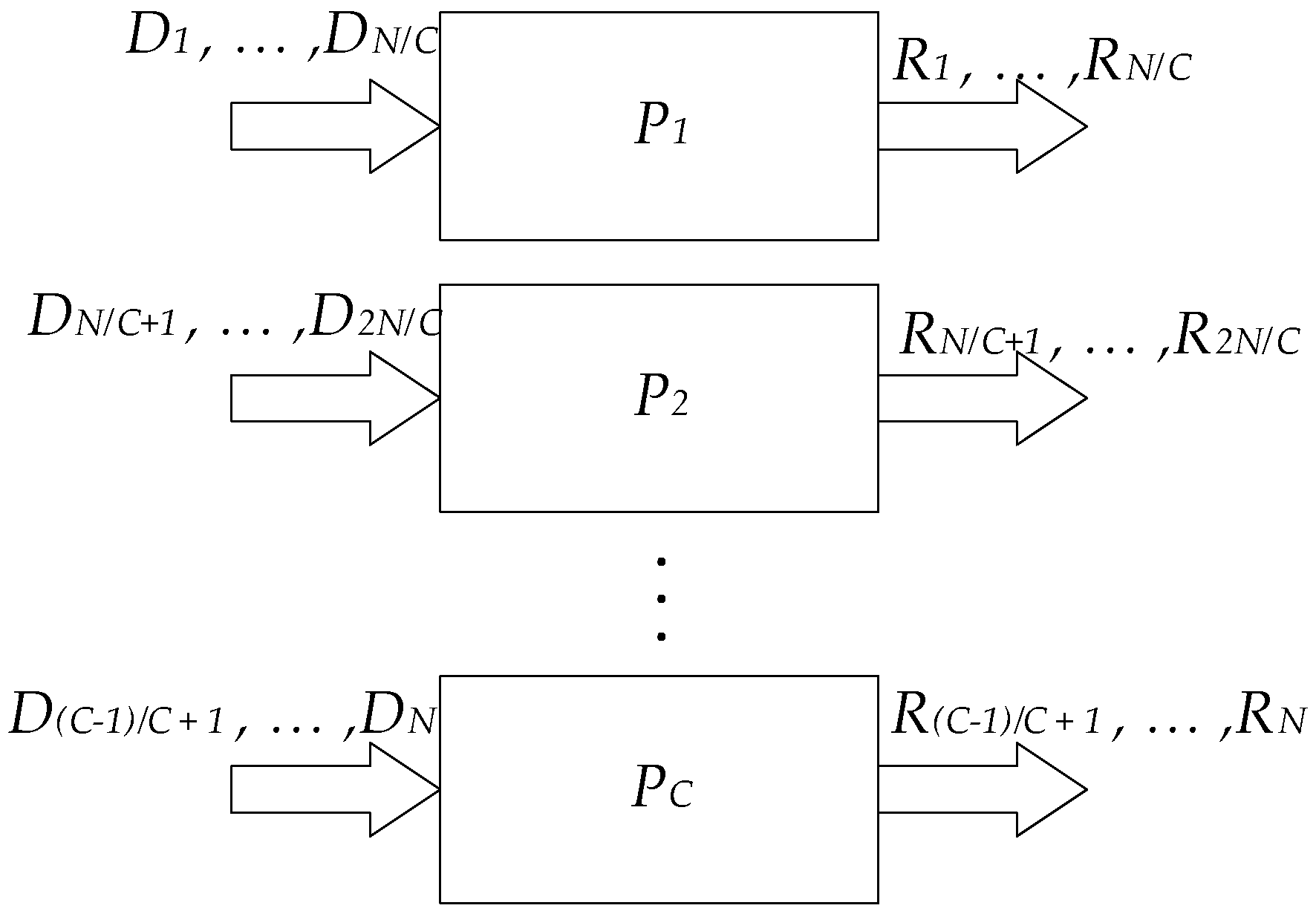
The main idea used to decrease computation time is to split the set of input vectors D i   ( i = 1 , 2 , ,   N ) into N/C disjoint subsets, where C is the number of processors P i   ( i = 1 , 2 , , C ) . Every processor P i   ( i = 1 , 2 , , C ) is configured to work with the set of operations O j ( i = 1 , 2 , , m ) and can be used to process one of the disjoint subsets independently. This allows for performing parallel computing on both software and hardware implementations of algorithms (Figure 3).
Thus, the total computation time required to obtain a solution can be calculated as follows:
T c o m p = N / C i = 1 M f ( O i ) τ ,
which is theoretically C-times less than the time required to obtain the same result without using parallel computing.
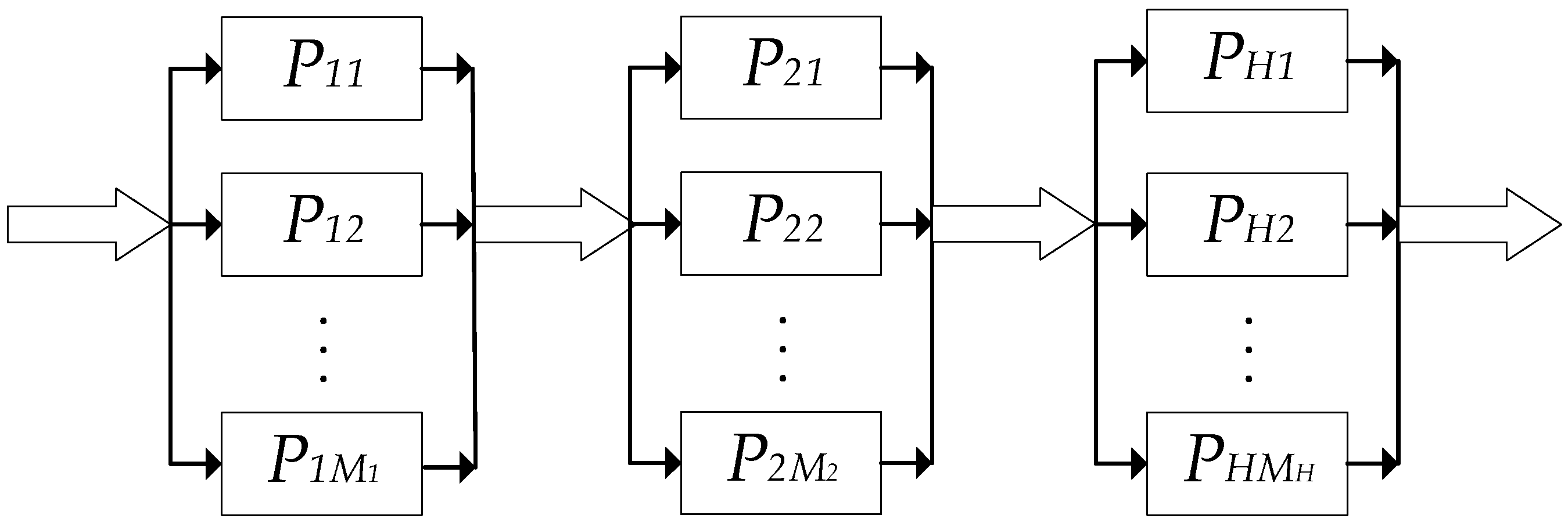
The computational efficiency can also be improved by using pipeline processing. The resulting structure can be described as an algorithm being divided into H consecutive operational stages. Thus, the amount of input and output data channels is decreased, but the whole process requires having a continuous flow of input data to the first operational stage, while it simultaneously does not have much effect on algorithms that have M     N .
If one wants to increase the computation speed of an algorithm and maintain the pipelining benefits, it is possible to improve the algorithm by adding parallelism to every operational stage (Figure 4).
Thus, the final computation time can be calculated as follows:
T c o m p = ( N + H 1 ) Δ T ,
and for the proposed example can be summarized as
Δ T = max i = 1 H ( T c o m p i ) = m a x i = 1 H ( m a x j = 1 M f ( O j i ) τ ) = m a x i = 1 M f ( O i ) τ ,
where m a x i = 1 M f ( O i ) —is the most computationally demanding operation.
In case when N is significantly large and M i M H , Equation (4) can be reorganized as:
T c o m p = N j = 1 M f ( O j ) τ H M H = H N j = 1 M f ( O j ) τ .
Thus, the total computation time can potentially be reduced by M H times, where M is the number of vertices of G(V,X) and H is the number of operational stages. The proposed scheme will be effective only in cases when all the vertices of the subgraph G ( V i , X i ) are informationally independent and can be implemented simultaneously (parallel).
In the general case, the operational vertices of subgraphs G ( V i , X i ) are information dependent, which means that some vertices v j V i cannot be realized until the result of the vertex v j 1 V i realization is obtained. Therefore, the maximum rate of pipeline processing and, as a consequence, the T c o m p of processing the entire set of input data can be ensured if the structure of connections between the stages of the pipeline is fully adequate to the topology of connections of vertices in the algorithm graph G ( V , X ) .
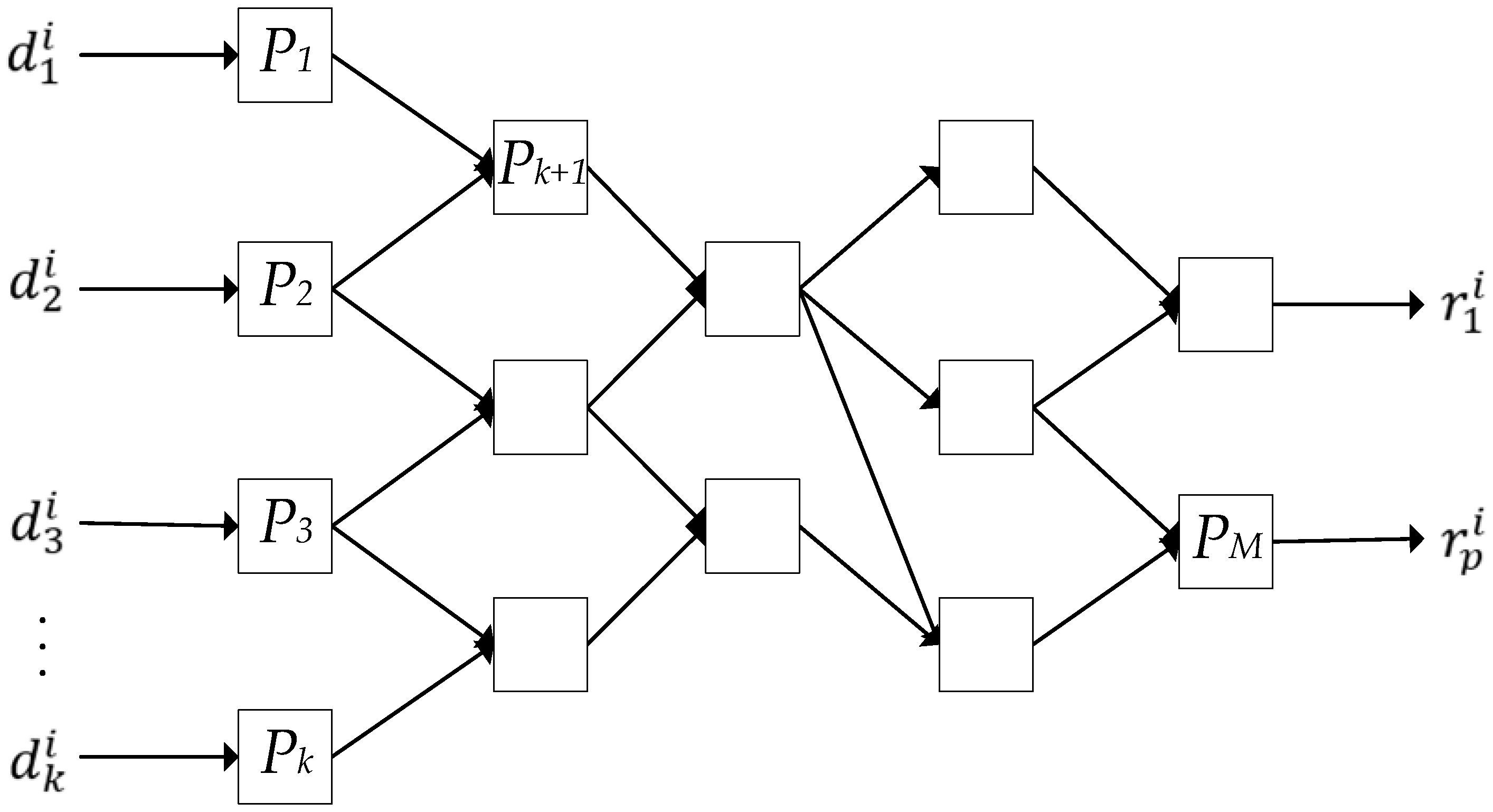
This way of organizing pipelined computations is called structural. The maximum processing rate can be achieved if each operational vertex v i ( i = 1 , 2 , , M ) of the algorithm graph is assigned its own processor element P i ( i = 1 , 2 , , M ) and links between P i are provided according to the topology information arcs of the graph G ( V , X ) (Figure 5).
If the vectors D i ( i = 1 , 2 , , N ) of the input set are sequentially fed to the input of such a computational structure, then their processing time will be T c o m p = ( N + H m a x 1 ) Δ T , where H m a x is the number of vertices on the critical path in the graph G ( V , X ) . The critical path is the path for which the value of j = 1 M f ( O j ) τ is maximum; O j ( j = 1 , 2 , , k ) are the operations belonging to the vertices of the critical path.
Δ T = m a x j = 1 H f ( O j ) τ is the execution time of the longest operation belonging to the vertices of the critical path. With a large value of N and considering that Δ T = max i = 1 , 2 , , H m f ( O j ) N j = 1 M f ( O j i ) M , one can obtain:
T c o m p = N M j = 1 M f ( O j ) τ .
Analyzing Equation (6), one can conclude that using the structural method of organization, it is possible to minimize the computation time in comparison with the other methods of organizing computing systems considered above (see (1), (2) and (5)).
The scheme shown in Figure 5 represents the proposed computational structure, which combines both parallel and pipelined methods of processing since the input data are processed simultaneously along different pipelined processor chains. The proposed structure is called a multi-pipeline computational structure and is considered the most efficient for solving stream problems [17].

3. Results

In this study, we consider a parallel modification of RK4—explicit Runge–Kutta method of accuracy order 4 [18,19], which is a standard ODE solver in most popular simulation packages, e.g., MATLAB, Wolfram Mathematica, and NI LabVIEW software.

3.1. Test Problem 1: A Simple Linear System

Let an initial value problem (IVP) be specified as follows:
d y d t = f ( y , t ) , y ( 0 ) = y 0 .
Pick a step size h > 0 and use recurrent formulas of the RK4 method as follows:
k 1 = f ( y i , t i ) ;
k 2 = f ( y i + h 2 k 1 , t i + h 2 ) ;
k 3 = f ( y i + h 2 k 2 , t i + h 2 ) ;
k 4 = f ( y i + h k 3 , t i + h ) ;
y i + 1 = y i + h 6 ( k 1 + 2 k 2 + k 3 + k 4 ) .
One can see that every formula from Equations (8)–(12) should be calculated sequentially, which excludes the possibility to organize parallel computing. Let us transform Equation (12) by substituting k 1 into the right side of (9), then substituting the calculated k 2 into (10), etc. To simplify the case, let us consider a simple ODE, which can be written as follows:
f ( y , t ) = a y + b x ( t ) ,
where x ( t ) = t , y 0 = 1 , a = 1 and b = 1. For this expression, Equation (12) can be rewritten taking (7) as (13) and expressing a common denominator:
y i + 1 = a 4 h 4 24 y i + a 3 b h 4 24 x i + a 3 h 3 6 y i + a 2 b h 3 12 ( x i + h 2 ) + a 2 b h 3 12 x i + a 2 h 2 2 y i + a b h 2 3 ( x i + h 2 ) + a b h 2 6 x i + a h y i + b h 6 ( x i + h ) + 2 b h 3 ( x i + h 2 ) + b h x i + y i .
Now, it is possible to express another common denominator to slightly decrease the number of mathematical operations and obtain the correct form, which can then be used for parallel hardware implementation:
y i + 1 = y i ( a 4 h 4 24 + a 3 h 3 6 + a 2 h 2 2 + a h ) + x i ( a 3 b h 4 24 + a 2 b h 3 12 + a b h 2 6 + b h ) + ( x i + h 2 ) ( a 2 b h 3 12 + a b h 2 3 + 2 b h 3 ) + b h 6 ( x i + h ) + y i .
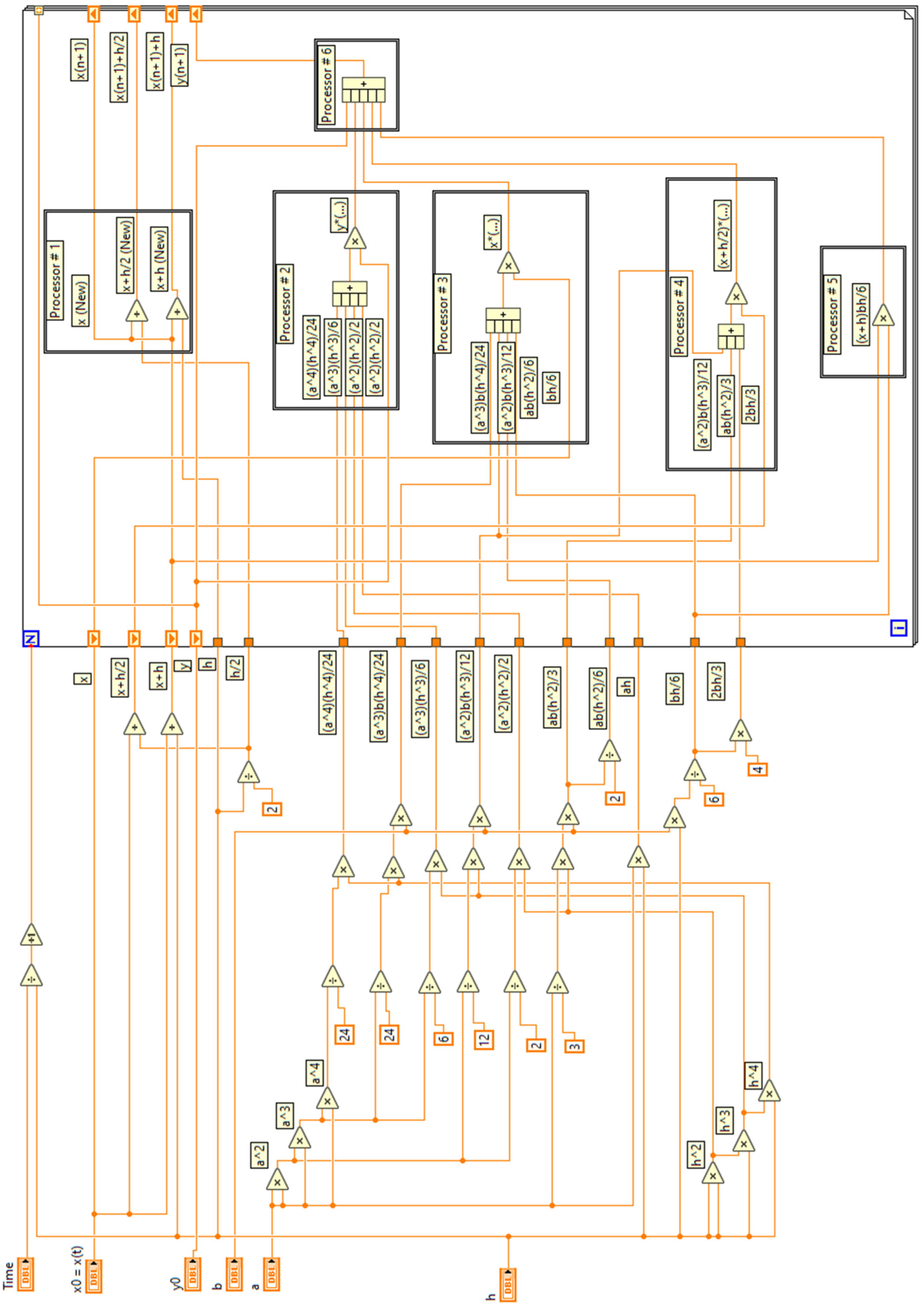
One can see that Equation (15) contains constants that can be excluded from parentheses and calculated preliminarily. This not only decreases the number of mathematical operations on every step of integration but allows one to use the proposed algorithm within the multi-pipeline computational structure (Figure A1).
ODE (13) can be solved analytically:
y ( t ) = b ( a t + e a t 1 ) a 2 + e a t .
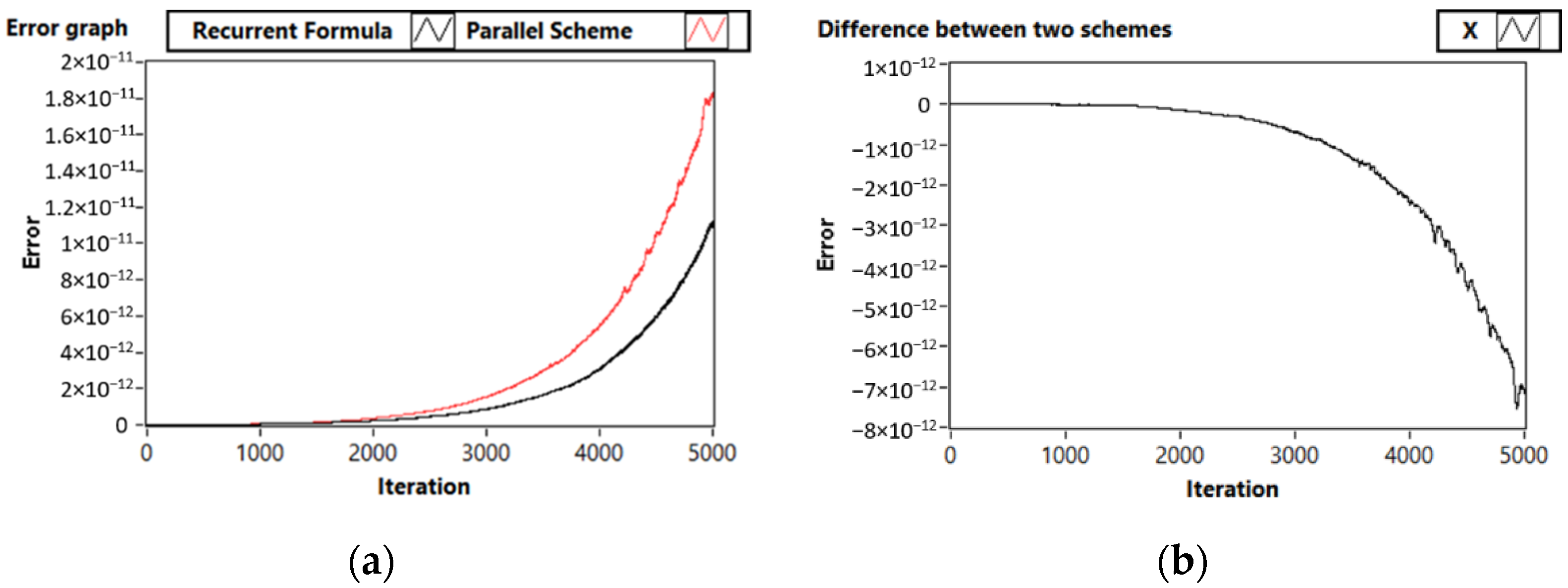
This analytical solution will be used to compare the original Runge–Kutta 4 method implementation with the proposed scheme. One can see from Figure 6 that the proposed parallel implementation maintains the truncation error of the conventional method.
One can see that the proposed structure (Figure 5) is suitable for hardware implementation using programmable logic devices and allows for organizing the computational process following the general principles of parallelism. In our study, we developed the concept of a hardware parallel ODE solver using NI FPGA technology. However, to perform this, one needs to apply a scaling procedure and turn the algorithm to using fixed-point arithmetic.
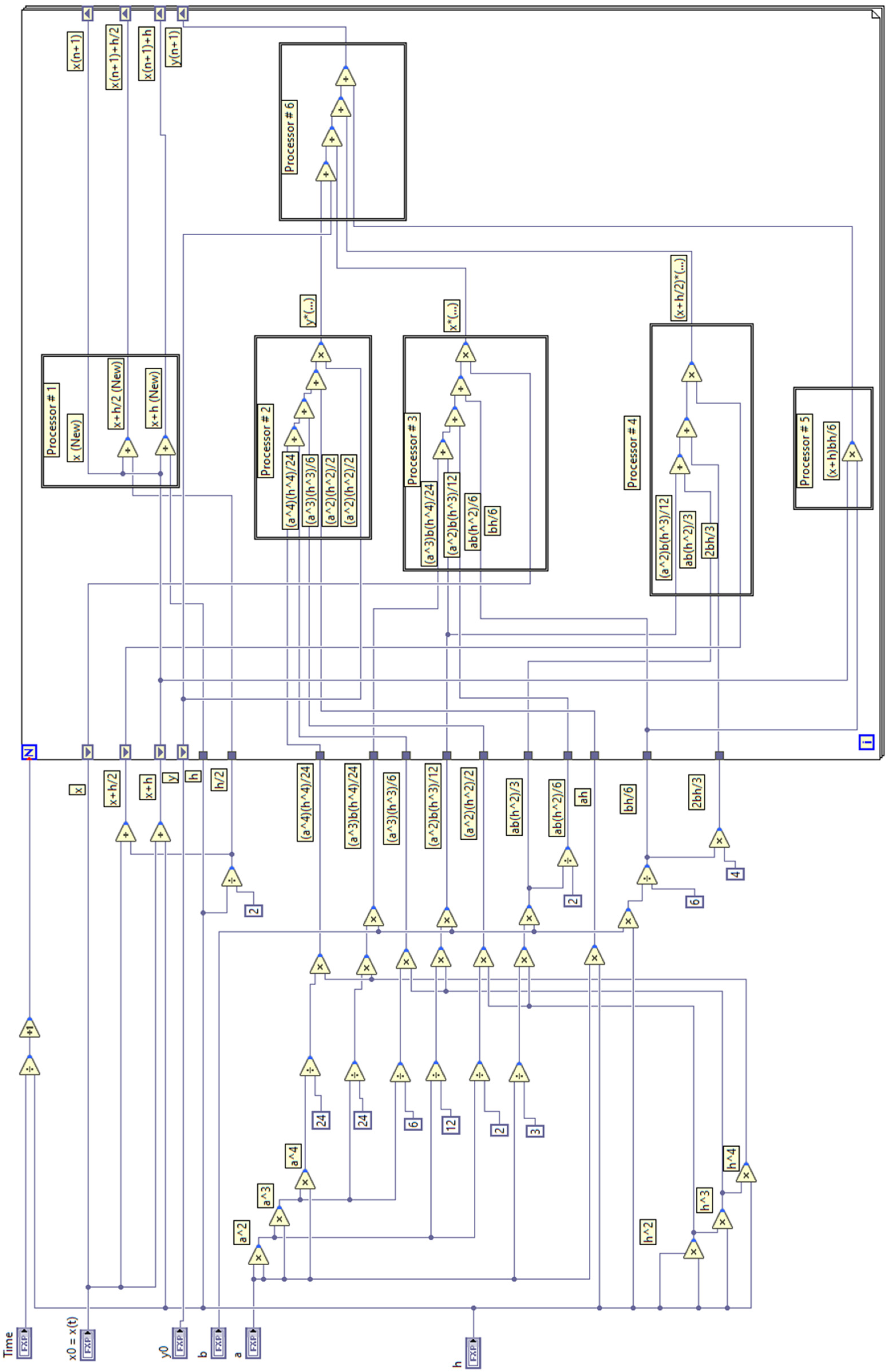
Conversion of the developed ODE solver with double data type (see Appendix A, Figure A1) to the solver with the fixed-point data type (Figure A2) was carried out using the scaling technique, previously reported in other works [20,21]. Following this methodology, in order to set the size of the integer and fractional parts, it is first necessary to determine the minimum and maximum possible value of each variable for the state of the system. To achieve this, a preliminary simulation of the system with the ODE solver of the double data type was carried out. Since the solution is exponential, it was decided to introduce restrictions on the simulation time for the integer ODE solver. In the course of the preliminary simulation, it was found that the optimal simulation time for a data type with a 32-bit machine word is an interval from 0 to 10 s. At this time interval of the solution, 17 bits are required to store the integer part of the state variables and parameters. Thus, all state variables and constant solver coefficients were converted to the FXP data type, where 1 bit is allocated to store the sign of the number, 17 bits are allocated to store the integer part, and the remaining bits are allocated to the fractional part. In the case of the fixed-point data type with a word length of 32 bits, 14 bits are allocated to the fractional part, which ensures that the solution’s accuracy compared to the original solver of the double data type will equal approximately 10 4 .
The proposed scheme (Figure A2) allows one to significantly increase computational efficiency, arranging six processors, five of which work parallel, in a cascade manner. However, it is impossible to directly compare the performance of a serial solver implemented on a PC and parallel solver implemented in a FPGA. Thus, we used Amdahl’s law [22] to theoretically assess a possible increase in computational efficiency:
S p = 1 α + 1 α p ,
where α is the percent of non-parallelizable operations and p is the number of processors. In the considered case, we have six processors, which are performing mathematical operations, while five of them are parallel and one uses their output data vectors and cannot be parallelized. To simplify calculations, let us state that they are performing the same operation of vector multiplication. Thus, using Formula (16), one can state that the potential increase in efficiency for a single non-parallel operation out of six operations performed by six different processors is:
S p = 1 0.16 + 1 0.16 6 ,
which gives 3.(33) for one step of integration. The obtained results show that the proposed technique allows one to significantly increase the performance of explicit Runge–Kutta solvers implemented in computers with non-von Neuman architecture. By comparing the performance of solvers for the IVP in the form of (13), one can make a general assumption on the potential performance increase. The explicit RK4 method in this case requires three non-parallelizable operations for every evaluation of the RHS function; thus, all four steps of the recurrent calculation plus the final step of y n + 1 point evaluation require 3 + 5 + 5 + 4 + 7 = 24 subsequent mathematical operations. The proposed scheme (Figure A2) divides the process into five parallelizable blocks of operations, where the most time and resource consuming blocks #2 and #3 require five operations each; thus, according to the idea of multi-pipeline structure, the general time to calculate 14 operations will be the same as it takes for 5 operations. The total amount of subsequent operations in that case equals 5 + 4 = 9 . Considering that time required to perform a single operation of either addition or multiplication on a middle-end machine with 8 core CPU is around 1,3E-6 s, one can make a general assumption on the possible performance increase by calculating the total time for a one-step evaluation using both classical and parallel implementations. Thus, for an IVP (13), total time elapsed on one evaluation step is around 0.0000312 and 0.0000117 s for classical and proposed parallel implementations of RK accordingly, which leads to a conclusion that the performance increase in the case of a linear system (13) will be about 2.(66)-times in comparison with the original scheme.
The solution of the previous sample ODE is an exponentially growing function, but the proposed technique can be used for any kind of IVP. Thus, let us consider another example—the oscillator case.

3.2. Test Problem 2: System with Periodic Solution

One can apply the proposed parallelizing technique when solving classical ODE systems with periodical solution:
{ d x d t = y d y d t = x .
First, expand Runge–Kutta recurrent formulas for Equation (17):
x n + 1 = x n h 6 ( h ( x n + h 2 y n ) + ( h ( x n + h 2 ( y n h 2 x n ) ) + ( h x n 6 y n ) ) )
y n + 1 = y n h 6 ( h ( y n h 2 x n ) + ( h ( y n h 2 ( x n + h 2 y ) ) + ( h y n + 6 x n ) ) )
x n + 1 = x n + h y n h 2 x n 2 h 3 y n 6 + h 4 x n 24
y n + 1 = y n h x n h 2 y n 2 + h 3 x n 6 + h 4 y n 24 ,
and simplify it one more time to further reduce the amount of mathematical operations:
x n + 1 = x n + y n ( h h 3 6 ) + x n ( h 4 24 h 2 2 )
y n + 1 = y n + x n ( h 3 6 h ) + y n ( h 4 24 h 2 2 ) ,
which leaves us with three coefficients:
a 1 = ( h h 3 6 ) ,
a 2 = ( h 3 6 h ) ,
a 3 = ( h 4 24 h 2 2 ) .
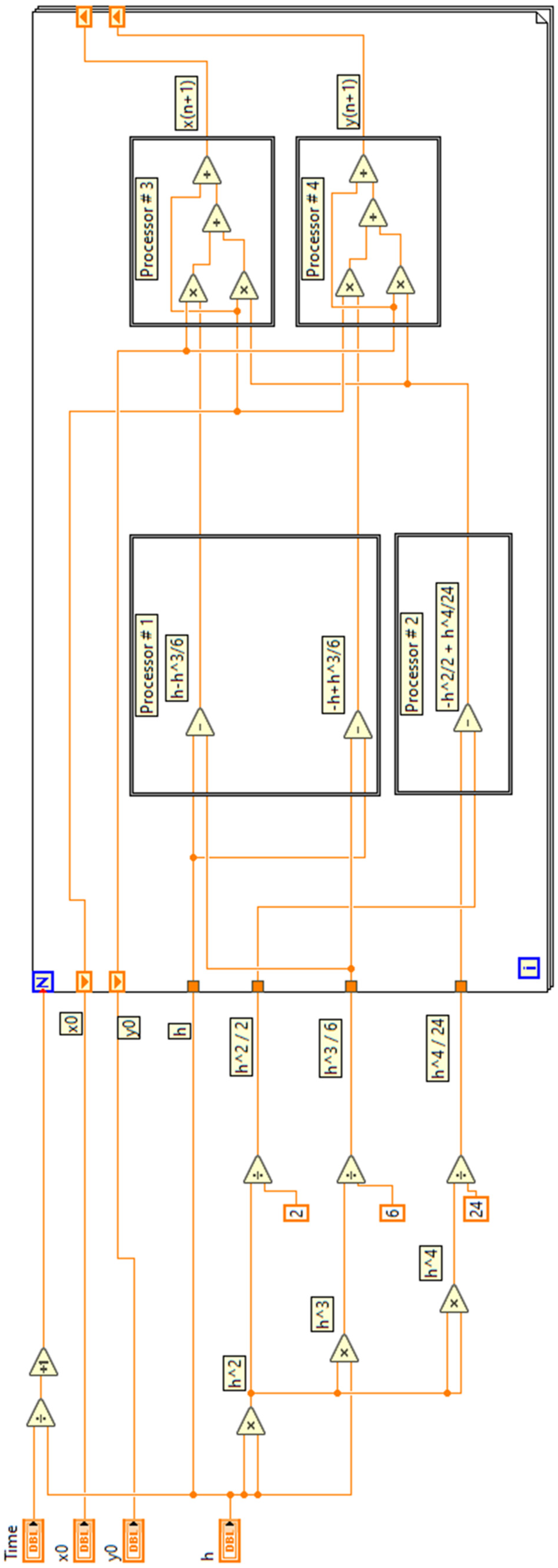
a 1 , a 2 , and a 3 can be used in multi-pipeline computation, as shown in Figure A3, or be pre-calculated outside of the integration cycle to further increase computational efficiency, allowing one step of integration to be performed in eight sequential operations (von Neumann architecture, processors #3 and #4 in Figure A3) or two-times faster, having two processors computing results simultaneously (parallel hardware implementation in FPGA).
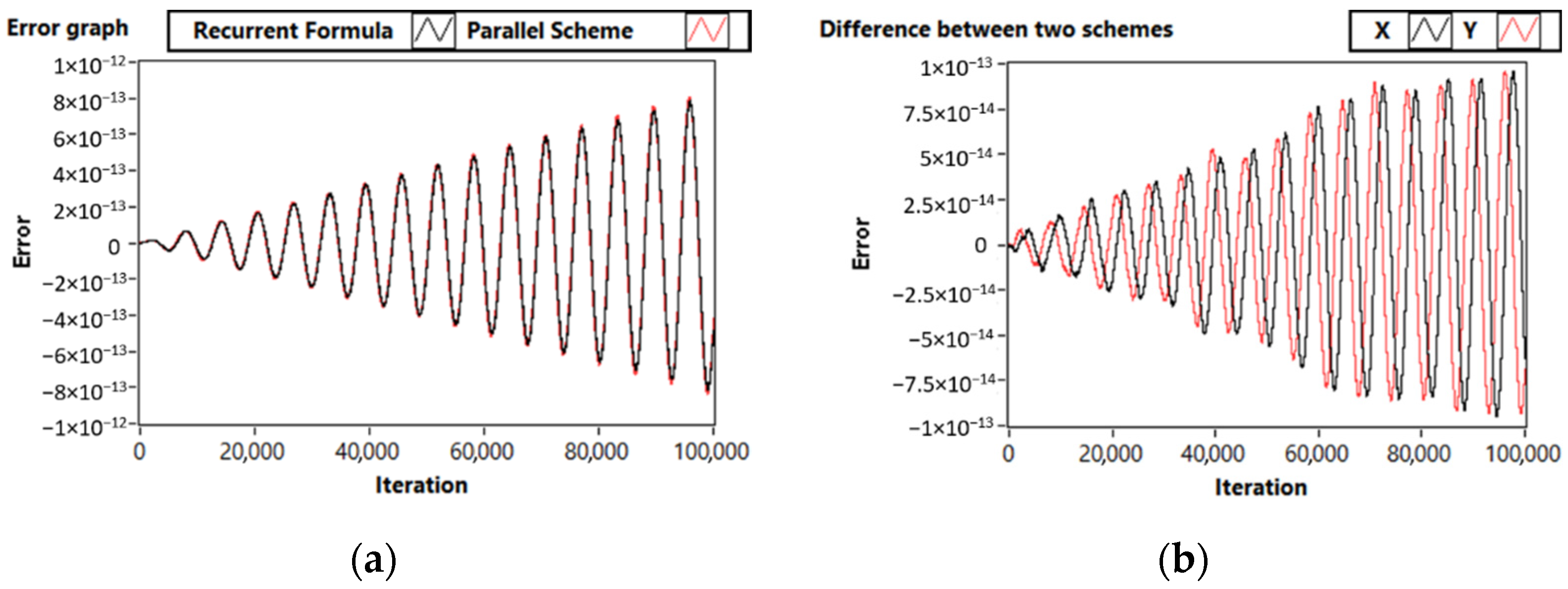
The comparison of accuracy for serial and parallel RK solvers obtained regarding analytical solution (18) is presented in Figure 7.
x ( t ) = cos ( t ) , y ( t ) = sin ( t ) .
One can see from Figure 7 that for an oscillatory system of order 2, the proposed parallel ODE solver does not possess an increased truncation error. Moreover, the observed difference is mostly a phase shift and the amplitude component of error is negligible. Let us consider an IVP of order 3 as a third test problem.

3.3. Test Problem 3: Third-Order System

It is known that the computation time needed for simulating systems of ODEs strictly depends on the dimension of the system. Systems of higher order require higher computation time. This especially stands for a case when all of the mathematical operations are being performed sequentially, and the higher the order of the system, the more efficient the proposed parallelization technique becomes due to the increasing amount of calculations on every step of recurrent formulas we can parallelize. Let us consider an ODE system of order 3 to evaluate this.
{ d x d t = 2 x + y + z d y d t = x + 2 y + z d z d t = x + y + 2 z
System (19) requires 27 sequential operations of multiplication and division and 33 operations of addition during the simulation cycle using classic recurrent Runge–Kutta formulas. Thus, having implemented parallel computation, it is possible to significantly decrease the computation time, having some of the operations either being performed outside of the simulation cycle or being computed using the proposed multi-pipeline computational structure. In this case, the parallelized Runge–Kutta formulas can be written as follows:
x n + 1 = x n + 2 h x n + h y n + h z n + 3 h 2 x n + 11 h 3 3 x n + 43 12 h 4 x n + 5 2 h 2 y n + 7 2 h 3 y n + 85 24 h 4 y n + 5 2 h 2 z n + 7 2 h 3 z n + 85 24 h 4 z n ,
y n + 1 = y n + h x n + 2 h y n + h z n + 3 h 2 y n + 11 h 3 3 y n + 43 12 h 4 y n + 5 2 h 2 x n + 7 2 h 3 x n + 85 24 h 4 x n + 5 2 h 2 z n + 7 2 h 3 z n + 85 24 h 4 z n ,
z n + 1 = z n + h x n + h y n + 2 h z n + 3 h 2 z n + 11 h 3 3 z n + 43 12 h 4 z n + 5 2 h 2 x n + 7 2 h 3 x n + 85 24 h 4 x n + 5 2 h 2 y n + 7 2 h 3 y n + 85 24 h 4 y n .
Following the abovementioned ideas, one can simplify those formulas further, ending with 33 operations of multiplication and division and 15 operations of addition:
x n + 1 = x n + x n ( 2 h + 3 h 2 + 11 3 h 3 + 43 12 h 4 ) + y n ( 5 2 h 2 + 7 2 h 3 + 85 24 h 4 + h ) + z n ( 5 2 h 2 + 7 2 h 3 + 85 24 h 4 + h ) ,
y n + 1 = y n + x n ( 5 2 h 2 + 7 2 h 3 + 85 24 h 4 + h ) + y n ( 2 h + 3 h 2 + 11 3 h 3 + 43 12 h 4 ) + z n ( 5 2 h 2 + 7 2 h 3 + 85 24 h 4 + h ) ,
z n + 1 = z n + x n ( 5 2 h 2 + 7 2 h 3 + 85 24 h 4 + h ) + y n ( 5 2 h 2 + 7 2 h 3 + 85 24 h 4 + h ) + z n ( 2 h + 3 h 2 + 11 3 h 3 + 43 12 h 4 ) .
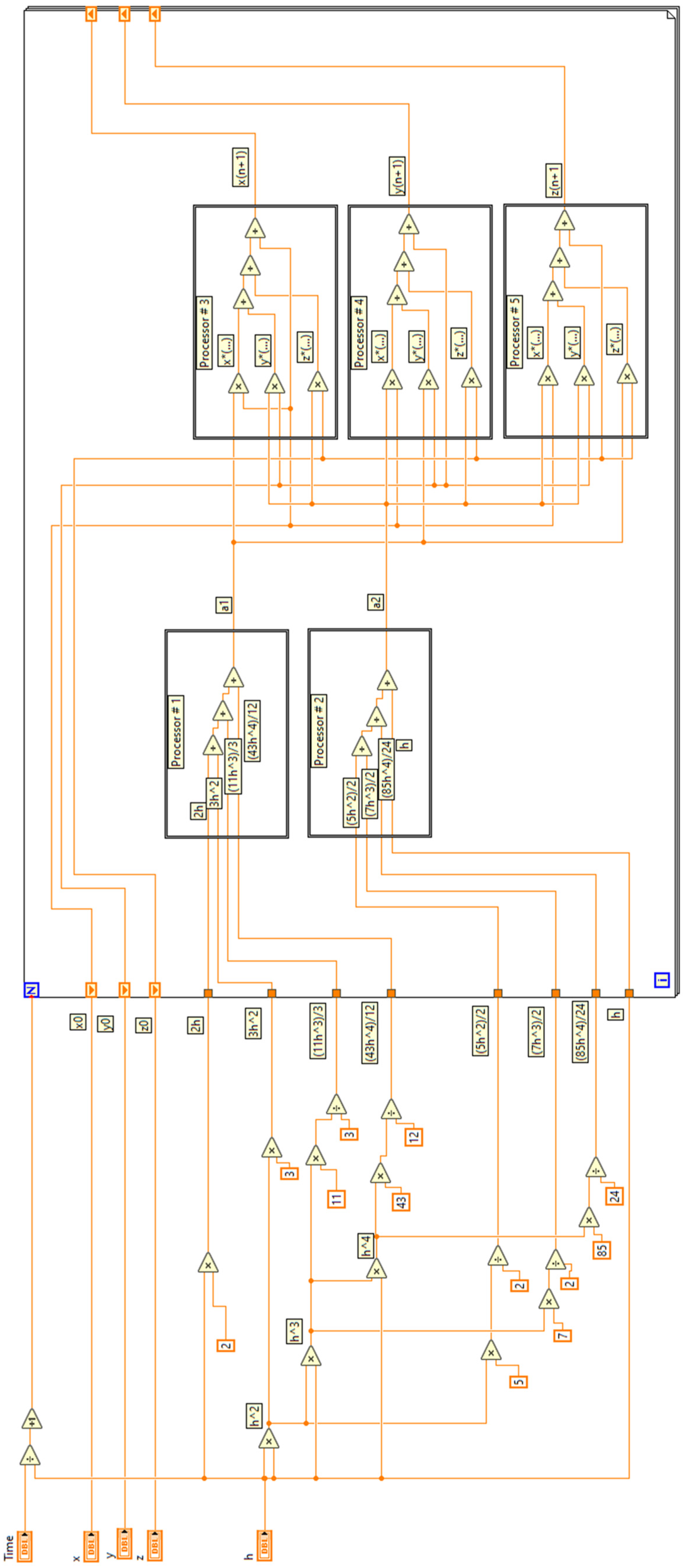
Thus, we obtain the coefficients, which can be pre-calculated (in that case, one will require a total of nine multiplications and nine additions per step, which can then be split into three separate groups with the possibility of parallel computation for FPGA implementation) or taken into computation inside of the integration cycle following the principles of multi-pipelining (Figure A4):
a 1 = ( 2 h + 3 h 2 + 11 3 h 3 + 43 12 h 4 ) ,
a 2 = ( 5 2 h 2 + 7 2 h 3 + 85 24 h 4 + h ) .
The analytical solution of the system (19) is known, which helps us to compare the results of the simulation with both sequential and parallel schemes:
x ( t ) = e t ( 3 e 3 t 2 ) , y ( t ) = e t + e 4 t , z ( t ) = e t + e 4 t .
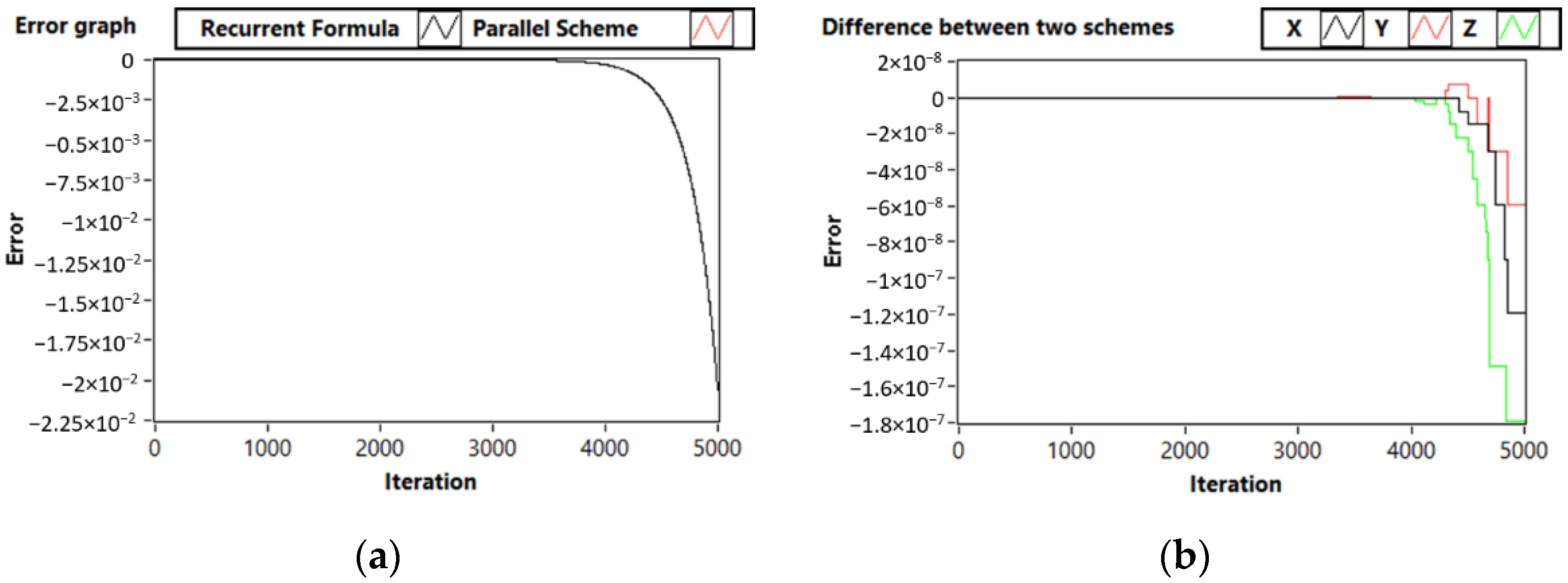
It was also of interest to analyze the accuracy order of the proposed scheme with initial values of x 0 = 1 ,   y 0 = 2 ,   z 0 = 2 (Figure 8).
One can evaluate the potential speedup of the proposed solver in a parallel case using Amdahl’s law. It is expected to be not less than three times for five-thread pipelining architecture. For systems of higher order, the advantage can be even more sufficient. Evaluating the strict dependence between the order of the simulated system and the calculations’ speedup will be the topic of our further research.

4. Conclusions

In this paper, we proposed a novel technique to parallelize explicit Runge–Kutta methods for an efficient hardware implementation of ODE solvers within the pipelining architecture. We described the proposed approach as an algorithm, illustrating it by solving three representative examples of ODEs.
We used the estimation of the truncation error to prove that the reported parallel implementation method does not significantly affect the precision of the method. We demonstrated the possibility of reducing computational costs while fully maintaining the properties of the original method. A hardware ODE solver architecture for FPGA implementation was created using the fixed-point scaling technique. It is shown that the performance gain obtained by parallelizing explicit RK solvers will increase with the order of simulated systems. It should be noted that the proposed solver architecture significantly reduces the complexity of converting Runge–Kutta algorithms to fixed-point hardware.
The obtained results can be applied to the development of high-speed hardware simulation systems. It is of interest to investigate the possibility of creating a high-precision control system using the proposed parallelizing approach and developing adaptive step-size techniques for parallel Runge–Kutta methods. These topics will be the key directions of our further studies.

Author Contributions

Conceptualization, K.Z.; data curation, V.A. and N.V.; formal analysis, P.F.; funding acquisition, V.A.; investigation, P.F., N.V. and K.Z.; methodology, P.F., K.Z. and D.K.; project administration, D.K.; resources, V.A. and N.V.; software, P.F. and V.A.; supervision, V.A. and D.K.; validation, D.K. and V.A.; visualization, P.F. and N.V.; writing—original draft, P.F. and V.A.; writing—review and editing, K.Z. and D.K. All authors have read and agreed to the published version of the manuscript.

Funding

This work is supported by the Russian Science Foundation, Project Number 22-41-04409.

Institutional Review Board Statement

Not applicable.

Conflicts of Interest

The authors declare no conflict of interest.

Appendix A

Figure A1. Graphical code for software ODE solver with parallel 5-processor computational structure for test problem (13). Double-precision floating point data type used.
Computation 10 00215 g0a1
Figure A2. Graphical code of hardware FPGA ODE solver with multi-pipeline parallel computational structure for test problem (13). Fixed-Point data type with scaling.
Computation 10 00215 g0a2
Figure A3. Graphical code for software ODE solver with parallel 2-processor computational structure for test problem (17). Floating point data type used.
Computation 10 00215 g0a3
Figure A4. Graphical code for software ODE solver with multi-pipeline parallel 3-processor computational structure for test problem (19). Floating-point data type used.
Computation 10 00215 g0a4

References

  1. Rahaman, H.; Hasan, M.K.; Ali, A.; Alam, M.S. Implicit Methods for Numerical Solution of Singular Initial Value Problems. Appl. Math. Nonlinear Sci. 2021, 6, 1–8. [Google Scholar] [CrossRef]
  2. Liu, D.; He, W. Numerical Simulation Analysis Mathematics of Fluid Mechanics for Semiconductor Circuit Breaker. Appl. Math. Nonlinear Sci. 2021, 7, 331–342. [Google Scholar] [CrossRef]
  3. Wang, Y. Application of numerical method of functional differential equations in fair value of financial accounting. Appl. Math. Nonlinear Sci. 2022, 7, 533–540. [Google Scholar]
  4. Xu, L.; Aouad, M. Application of Lane-Emden differential equation numerical method in fair value analysis of financial accounting. Appl. Math. Nonlinear Sci. 2021, 7, 669–676. [Google Scholar] [CrossRef]
  5. Hairer, E.; Nørsett, S.P.; Wanner, G. Solving Ordinary Differential Equations I: Nonstiff probleme; Springer: Berlin/Heidelberg, Germany, 1993. [Google Scholar]
  6. Press, W.H.; Teukolsky, S.A.; Vetterling, W.T.; Flannery, B.P. Numerical Recipes in C++." The Art of Scientific Computing, 2nd ed.; Cambridge University Press: Cambridge, UK, 2007; p. 1002. [Google Scholar]
  7. Butusov, D.N.; Karimov, A.I.; Tutueva, A.V. Hardware-targeted semi-implicit extrapolation ODE solvers. In Proceedings of the 2016 International Siberian Conference on Control and Communications (SIBCON), Moscow, Russia, 12–14 May 2016. [Google Scholar]
  8. Butusov, D.N.; Ostrovskii, V.Y.; Tutueva, A.V. Simulation of dynamical systems based on parallel numerical integration methods. In Proceedings of the 2015 IEEE NW Russia Young Researchers in Electrical and Electronic Engineering Conference (EIConRusNW), St. Petersburg, Russia, 2–4 February 2015. [Google Scholar]
  9. Saralegui, R.; Sanchez, A.; Martinez-Garcia, M.S.; Novo, J.; de Castro, A. Comparison of numerical methods for hardware-in-the-loop simulation of switched-mode power supplies. In Proceedings of the 2018 IEEE 19th Workshop on Control and Modeling for Power Electronics (COMPEL), Padua, Italy, 25–28 June 2018; pp. 1–6. [Google Scholar] [CrossRef]
  10. Farhani Baghlani, F.; Chamgordani, A.E.; Shalmani, A.N. HARDWARE IMPLEMENTATION OF NUMERICAL SOLUTION OF DIFFERENTIAL EQUATIONS ON FPGA. Sharif J. Mech. Eng. 2017, 33, 93–99. [Google Scholar]
  11. Liu, C.; Wu, H.; Feng, L.; Yang, A. Parallel fourth-order Runge-Kutta method to solve differential equations. In International Conference on Information Computing and Applications; Springer: Berlin/Heidelberg, Germany, 2011. [Google Scholar]
  12. Ding, X.-H.; Geng, D.-H. The convergence theorem of parallel Runge-Kutta methods for delay differential equation. J. Nat. Sci. Heilongjiang Univ. 2004, 21, 17–22. [Google Scholar]
  13. Jinggao, F. A class of parallel runge-kutta methods for differential-algebraic systems of index 2. J. Syst. Eng. Electron. 1999, 10, 64–75. [Google Scholar]
  14. Bashashin, M.; Nechaevskiy, A.; Podgainy, D.; Rahmonov, I. Parallel algorithms for studying the system of long Josephson junctions. In Proceedings of the CEUR Workshop Proceedings, Stuttgart, Germany, 19 February 2019. [Google Scholar]
  15. Volokhova, A.V.; Zemlyanay, E.V.; Kachalov, V.V.; Rikhvitskiy, V.S. Simulation of the gas condensate reservoir depletion. Comput. Res. Model. 2020, 12, 1081–1095. [Google Scholar] [CrossRef]
  16. Tang, H.C. Parallelizing a Fourth-Order Runge-Kutta Method; US Department of Commerce, Technology Administration, Nation-al Institute of Standards and Technology: Gaithersburg, MD, USA, 1997. [Google Scholar]
  17. Jiang, W.; Yang, Y.-H.E.; Prasanna, V.K. Scalable multi-pipeline architecture for high performance multi-pattern string matching. In Proceedings of the 2010 IEEE International Symposium on Parallel & Distributed Processing (IPDPS), Atlanta, GA, USA, 19–23 April 2010. [Google Scholar]
  18. Runge, C. Über die numerische Auflösung von Differentialgleichungen. Math. Ann. 1895, 46, 167–178. [Google Scholar] [CrossRef] [Green Version]
  19. Kutta, W. Beitrag zur naherungsweisen integration totaler differentialgleichungen. Z. Math. Phys. 1901, 46, 435–453. [Google Scholar]
  20. Andreev, V.S.; Goryainov, S.V.; Krasilnikov, A.V.; Sarma, K.K. Scaling techniques for fixed-point chaos generators. In Proceedings of the 2017 IEEE Conference of Russian Young Researchers in Electrical and Electronic Engineering (EIConRus), St. Petersburg and Moscow, Russia, 1–3 February 2017. [Google Scholar]
  21. Andreev, V.; Ostrovskii, V.; Karimov, T.; Tutueva, A.; Doynikova, E.; Butusov, D. Synthesis and Analysis of the Fixed-Point Hodgkin–Huxley Neuron Model. Electronics 2020, 9, 434. [Google Scholar] [CrossRef]
  22. Amdahl, G.M. Validity of the single processor approach to achieving large scale computing capabilities, reprinted from the afips con-ference proceedings, vol. 30 (atlantic city, nj, apr. 18–20), afips press, reston, va., 1967, pp. 483–485, when dr. amdahl was at international business machines corporation, sunnyvale, california. IEEE Solid-State Circuits Soc. Newsl. 2007, 12, 19–20. [Google Scholar]
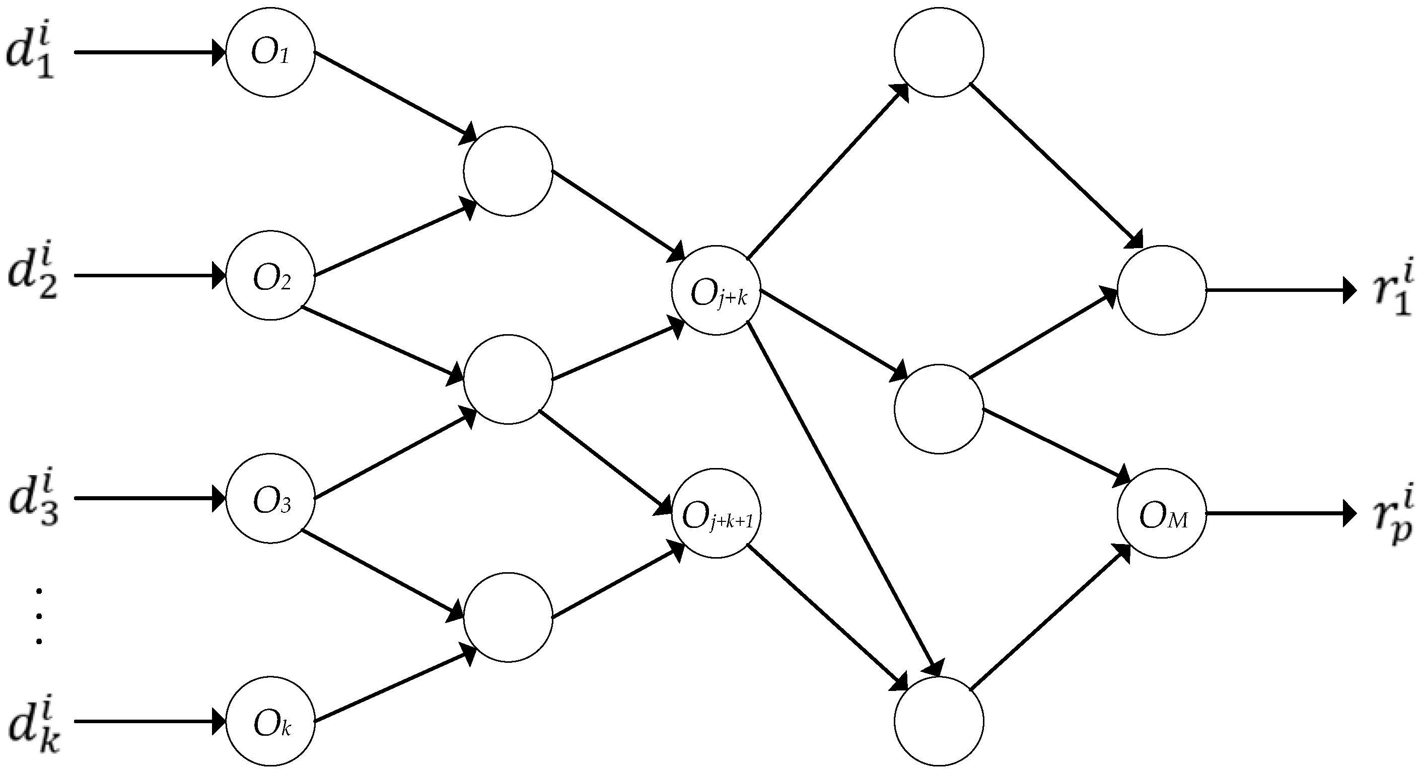
Figure 1. Streaming algorithm graph.
Computation 10 00215 g001
Figure 2. Operations in typical computer with von Neumann architecture.
Computation 10 00215 g002
Figure 3. Scheme representing a parallel computing process.
Computation 10 00215 g003
Figure 4. The use of parallel processors in relation to pipeline strategy.
Computation 10 00215 g004
Figure 5. The proposed multi-pipeline computational structure.
Computation 10 00215 g005
Figure 6. Absolute truncation error plots given relatively to the analytical solution for classical serial Runge–Kutta method and proposed parallel scheme (a). Difference between the truncation errors of parallel and serial solvers (b). Simulation time 5 s, step value 0.001 s.
Computation 10 00215 g006
Figure 7. Absolute truncation error plots given relatively to the analytical solution for recurrent Runge–Kutta method and proposed parallel scheme (a). Difference between the truncation errors for parallel and serial solvers (b). Simulation time 100 s, step size value 0.001 s.
Computation 10 00215 g007
Figure 8. Absolute truncation error plots given relatively to the analytical solution for the recurrent Runge–Kutta method and proposed parallel scheme (a). Difference between the truncation errors for parallel and serial solvers (b). Simulation time 5 s, step size value 0.001 s.
Computation 10 00215 g008
Publisher’s Note: MDPI stays neutral with regard to jurisdictional claims in published maps and institutional affiliations.