
Relay Node Selection Methods for UAV Navigation Route Constructions in Wireless Multi-Hop Network Using Smart Meter Devices

 , , , and
Abstract
1. Introduction
2. Safe and Efficient UAV Route Construction Method over Wireless Multi-Hop Network
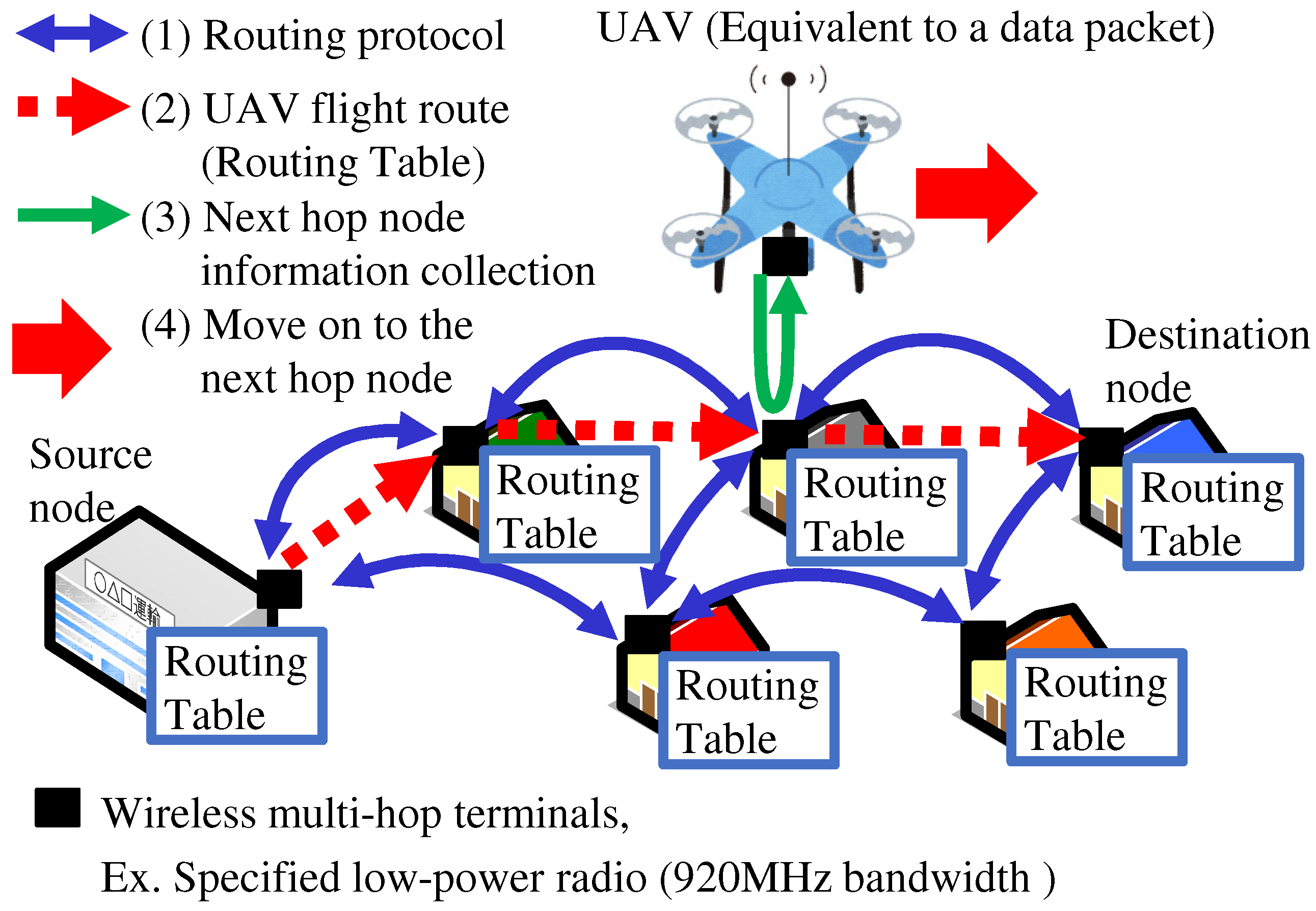
- (1)
- Each node exchanges routing protocol packets to construct the UAV flight route.
- (2)
- Each node creates a routing table for the UAV flight route from the source node to the destination node.
- (3)
- When the UAV arrives over a relay node on its flight route, it queries the node for information about the next hop node.
- (4)
- The UAV moves towards the next hop node. Repeating (3) and (4), the UAV follows the relay nodes and arrives at the destination node.
2.1. UAV Navigation Network Topology
2.2. Method for Constructing Optimal Routes in Terms of Distance and Safety Based on OLSR
2.2.1. Optimized Link State Routing Protocol (OLSR)
2.2.2. Dijkstra Method
2.2.3. Method for Constructing Optimal Routes Based on OLSR
| Algorithm 1 Algorithm for constructing optimal UAV routes based on OLSR. |
|
3. Relay Node Selection Issue
4. Related Works
5. Proposed Method
5.1. Method of Randomly Selecting Relay Nodes
- (1)
- When a node i is activated, a value from 1 to 100 is randomly assigned as the cut-off value .
- (2)
- The relay function is operated for the node whose cut-off value is less than the “relay function activation cut-off value ()”. The node i that satisfies the conditions of Equation (2) is selected as the relay node.
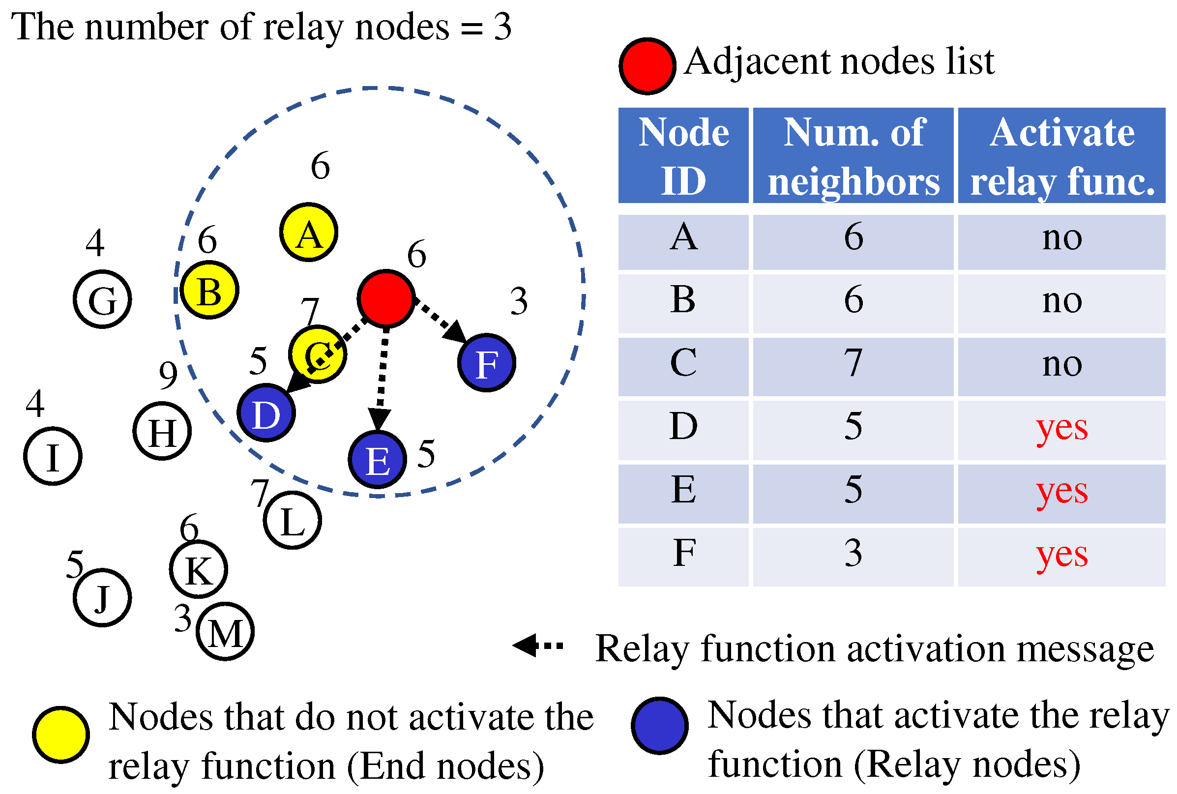
5.2. Method of Selecting Nodes That Connect to More Adjacent Nodes
- (1)
- In the node i, the number of adjacent nodes can be obtained from the source address of the received HELLO message.
- (2)
- Each node sends the number of adjacent nodes to the adjacent nodes by the HELLO messages. The M denotes the set of s that are received from adjacent nodes.
- (3)
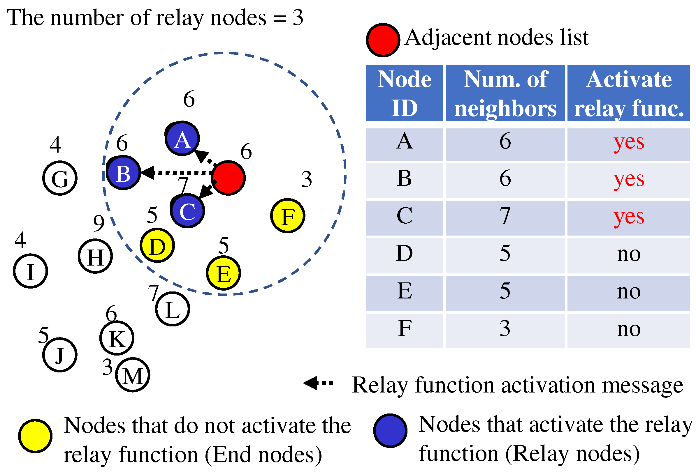
- As shown in Figure 6, each node selects the nodes among its adjacent nodes that have more adjacent nodes and notifies the selected nodes that they should activate the relay function. Each node is set as “the number of relay nodes (N)” in advance. The node i whose satisfies the conditions of Equation (3) is selected as the relay node.
5.3. Method of Selecting Nodes That Connect to Fewer Adjacent Nodes
5.4. Method Using MPR
- (1),(2)
- are the same as “more adjacent nodes”.
- (3)
- The node receiving a HELLO message knows which node is two hops away (2-hop neighbors). N is the subset of neighbors in all nodes. is the subset of 2-hop neighbors. is the neighbors of node i. is defined as the number of neighbors of node i, M is the MPR set.
- (4)
- As shown in Algorithm 2 and Figure 8, the node selects the MPR set with the smallest number of neighbors connecting to all nodes two hops away.
- (5)
- One of the nodes with the lowest number of neighbors is selected as a relay node; then, its MPR set is selected as a relay node; then, the MPR set of the relay node is selected as a relay node, and so on; all relay nodes are selected through sequential propagation.
| Algorithm 2 Algorithm for method using MPR. |
|

6. Evaluation
6.1. Evaluation Perspectives
6.1.1. Parameter Values That Meet Requirements
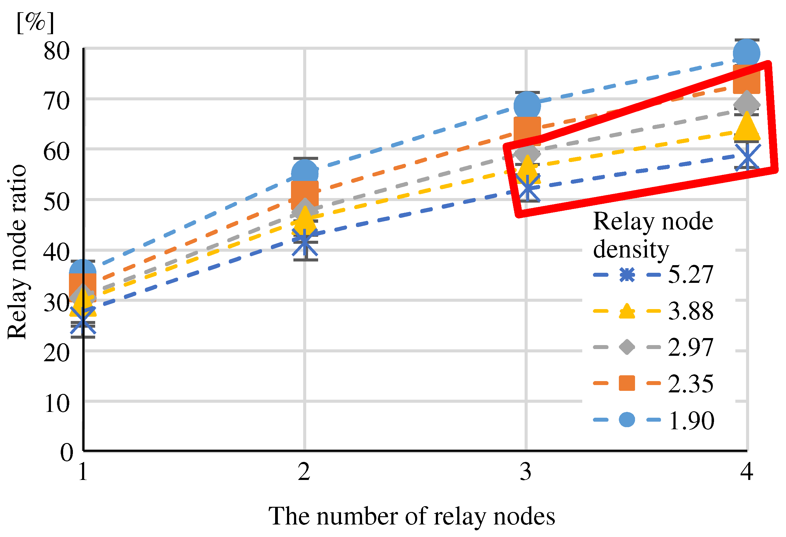
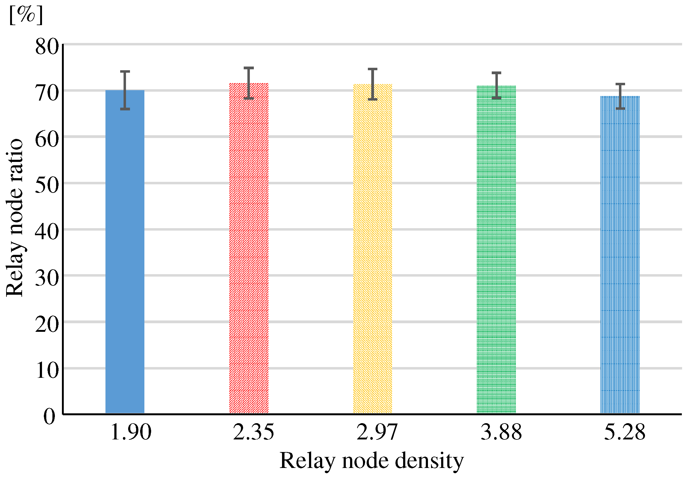
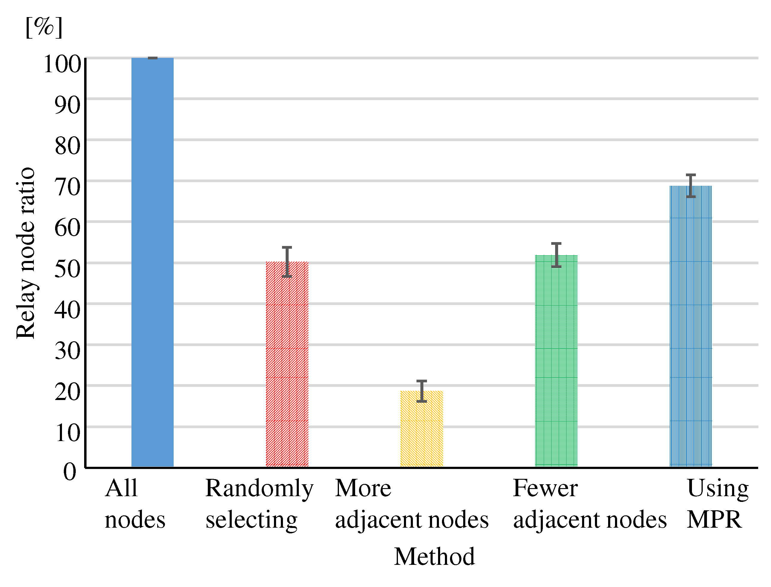
6.1.2. Relay Node Ratio
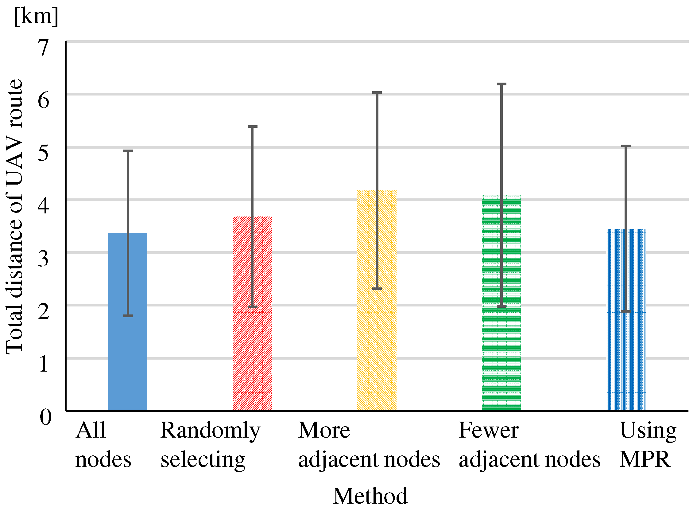
6.1.3. Optimality of the Route
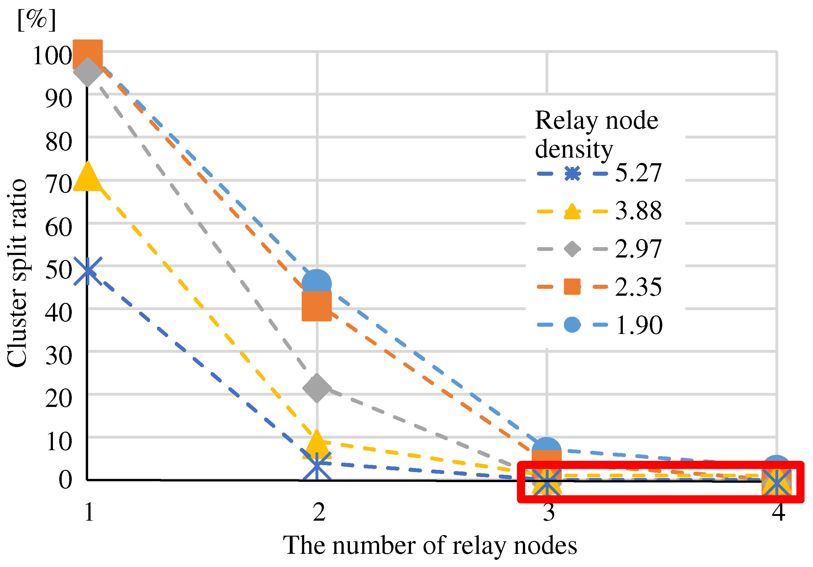
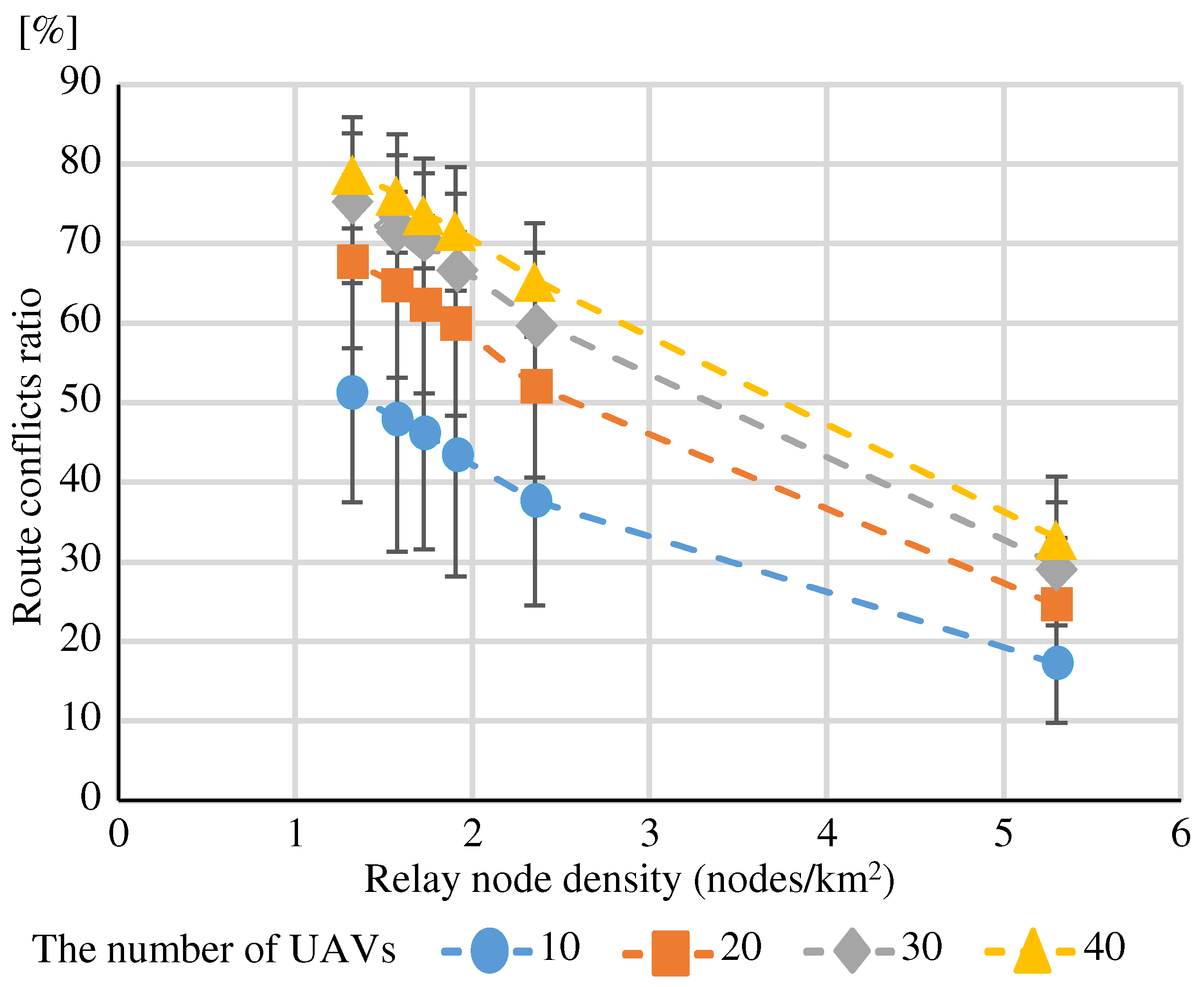
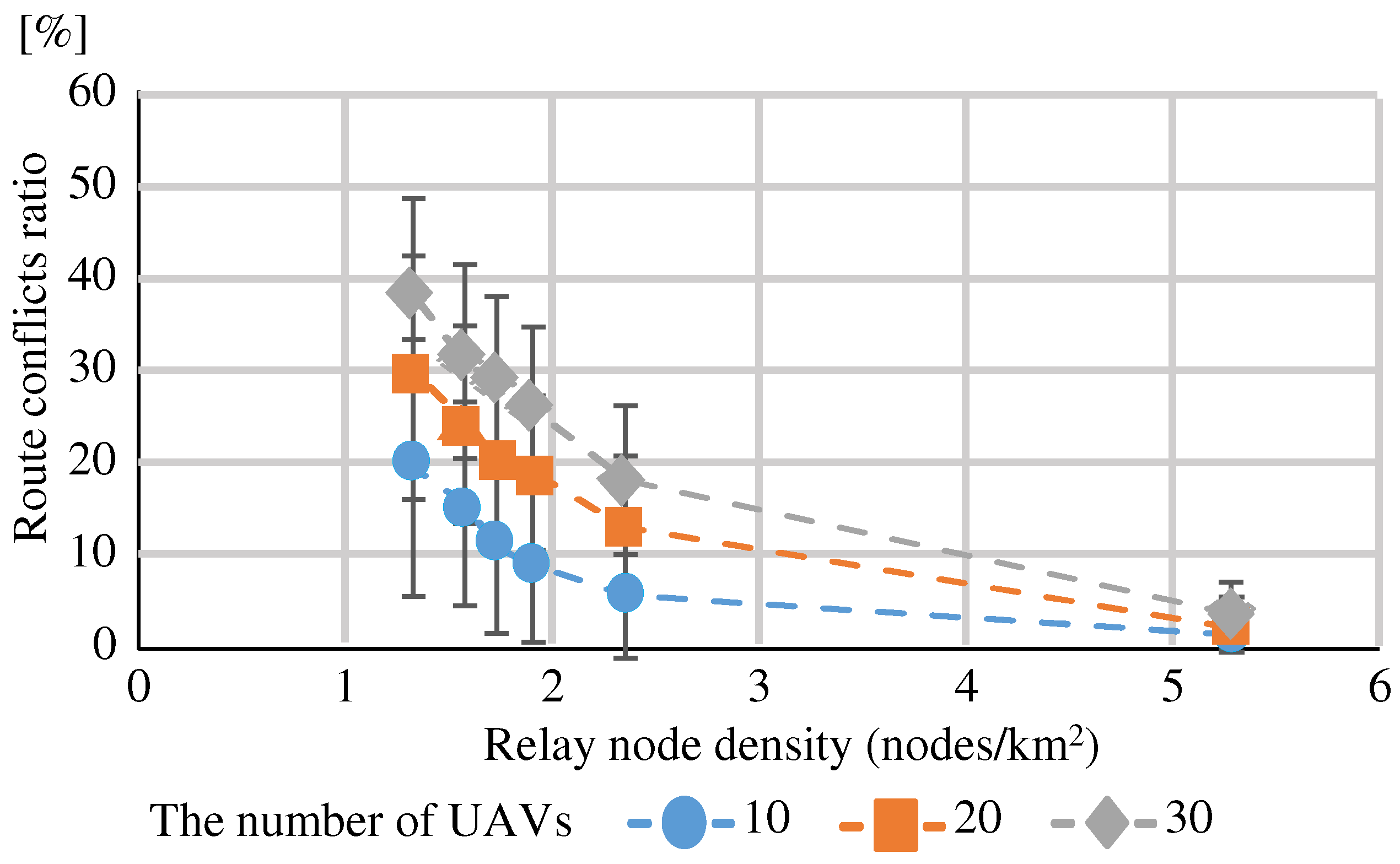
6.1.4. Route Conflicts Ratio
6.2. Evaluation Method
- In addition to the four proposed methods, we experimented with a method in which all nodes have the relay function enabled (hereafter, “all nodes”).
- For Eval. 1 and Eval. 2, we created a simulator in C++ to experiment on the relay node selection by each method. Eval. 3 and Eval. 4 use the OLSR-based method for route construction. Using the NS-3 network simulator [59] version 3.30, the OLSR simulation software was modified to add OLSR-based signal processing and an information repository, and simulation experiments were conducted.
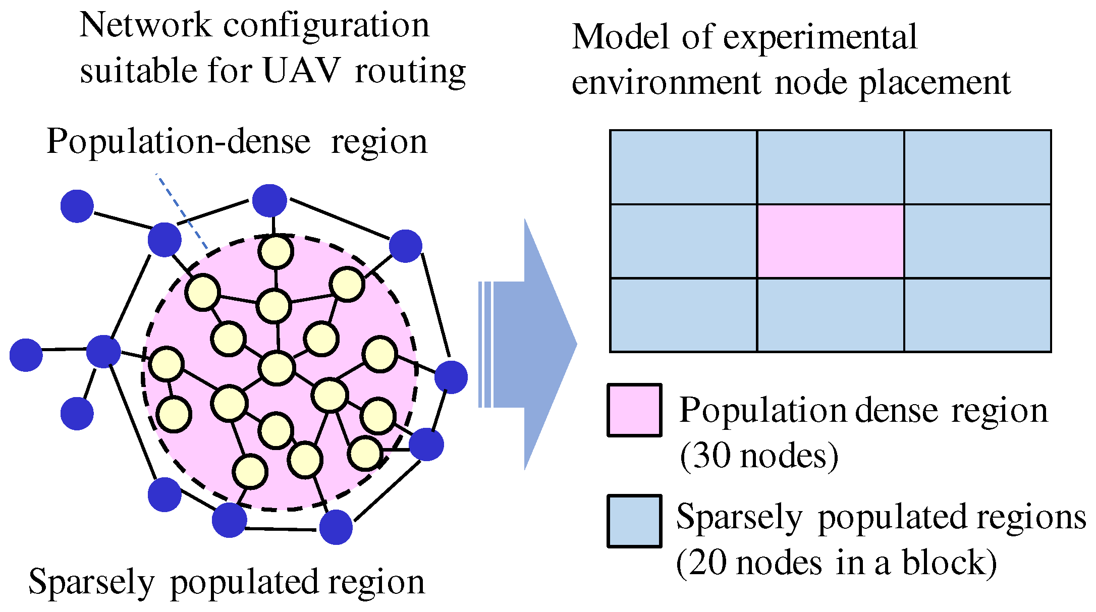
- Simulation experiments were carried out using the node arrangement model based on a regional city as shown in Figure 9. A population-dense region is located in the center, surrounded by sparsely populated regions. A total of 30 nodes were placed in population-dense region and 20 nodes were placed in each of the 8 blocks in sparsely populated regions.
- The simulation randomly places nodes in each block with the relay node densities shown in Table 1.
- The radio propagation range of each node is 1.5 km, and no nodes are added, deleted, or moved.
- Eval. 3 randomly selects source and destination nodes from sparsely populated regions. Eval. 4 randomly selects source and destination nodes from both population-dense regions and sparsely populated regions.
- We repeat the relay node selection and the route construction 100 times for each method and calculate the mean and standard deviation for each evaluation perspective.
6.3. Evaluation Results
6.3.1. Parameter Values That Meet Requirements, Relay Node Ratio
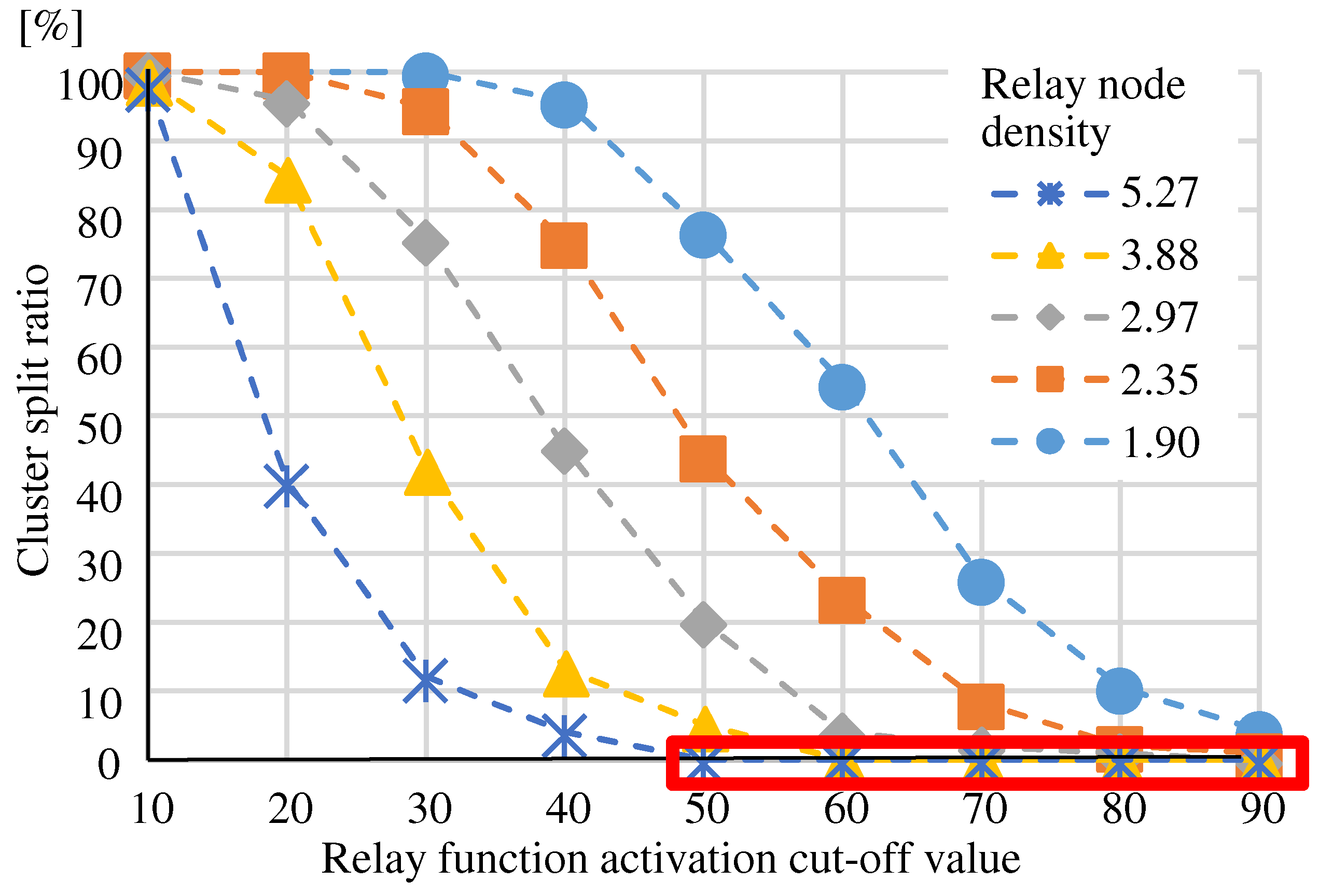
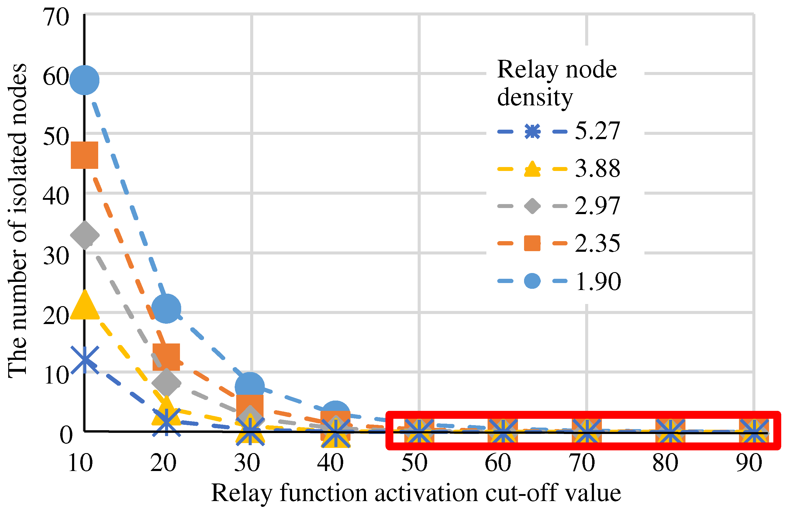
Method of Randomly Selecting Relay Nodes
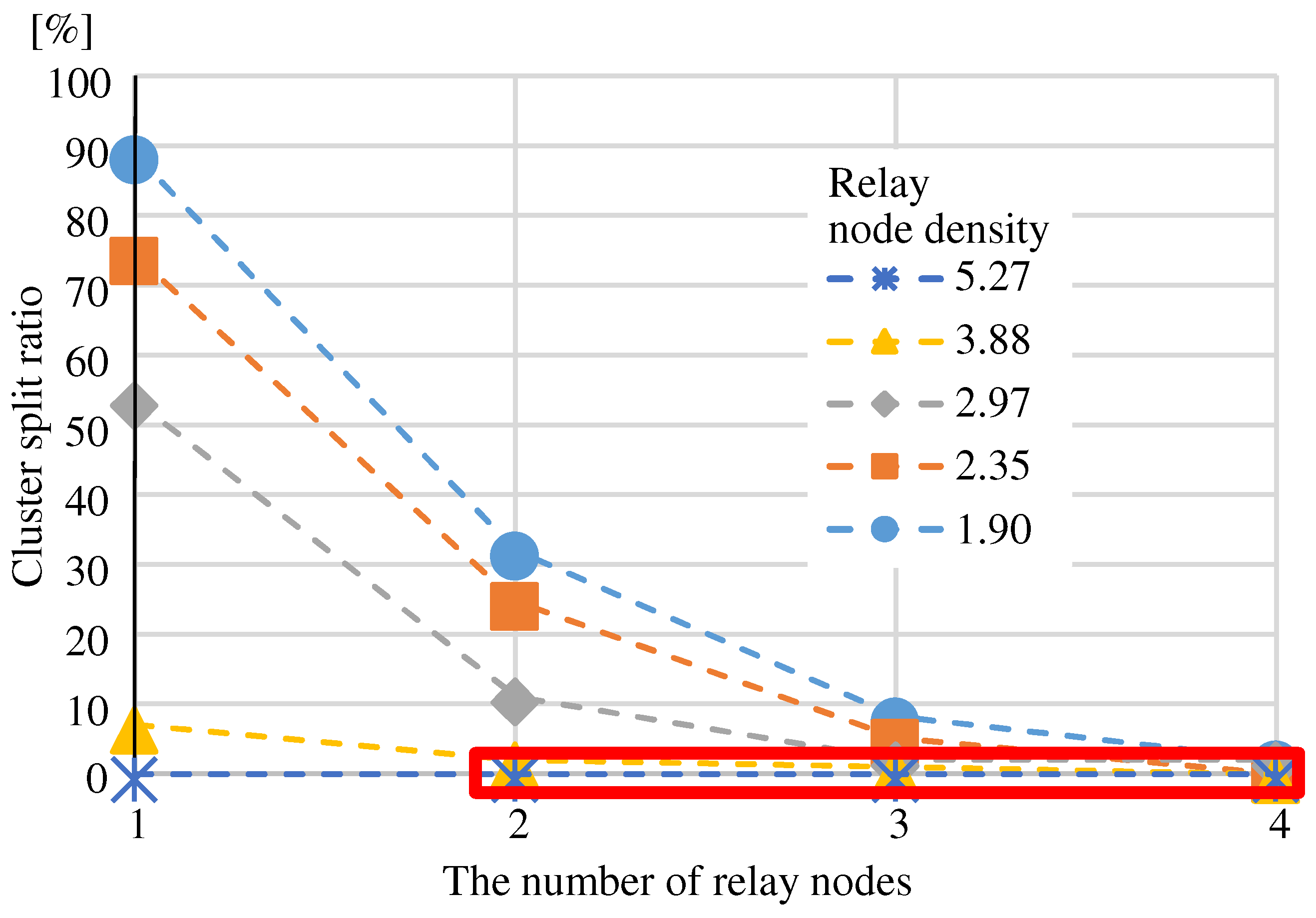
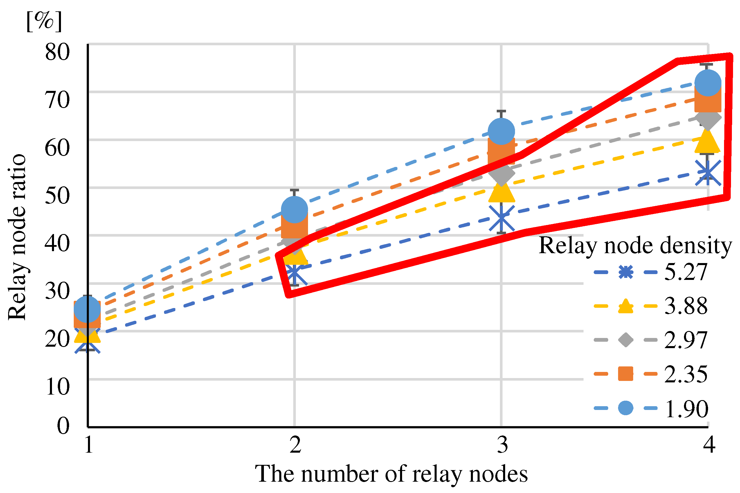
Method of Selecting Nodes That Connect to More Adjacent Nodes

Method of Selecting Nodes That Connect to Fewer Adjacent Nodes
Method Using MPR
6.3.2. Optimality of the Route
Relay Node Ratio
Total Distance
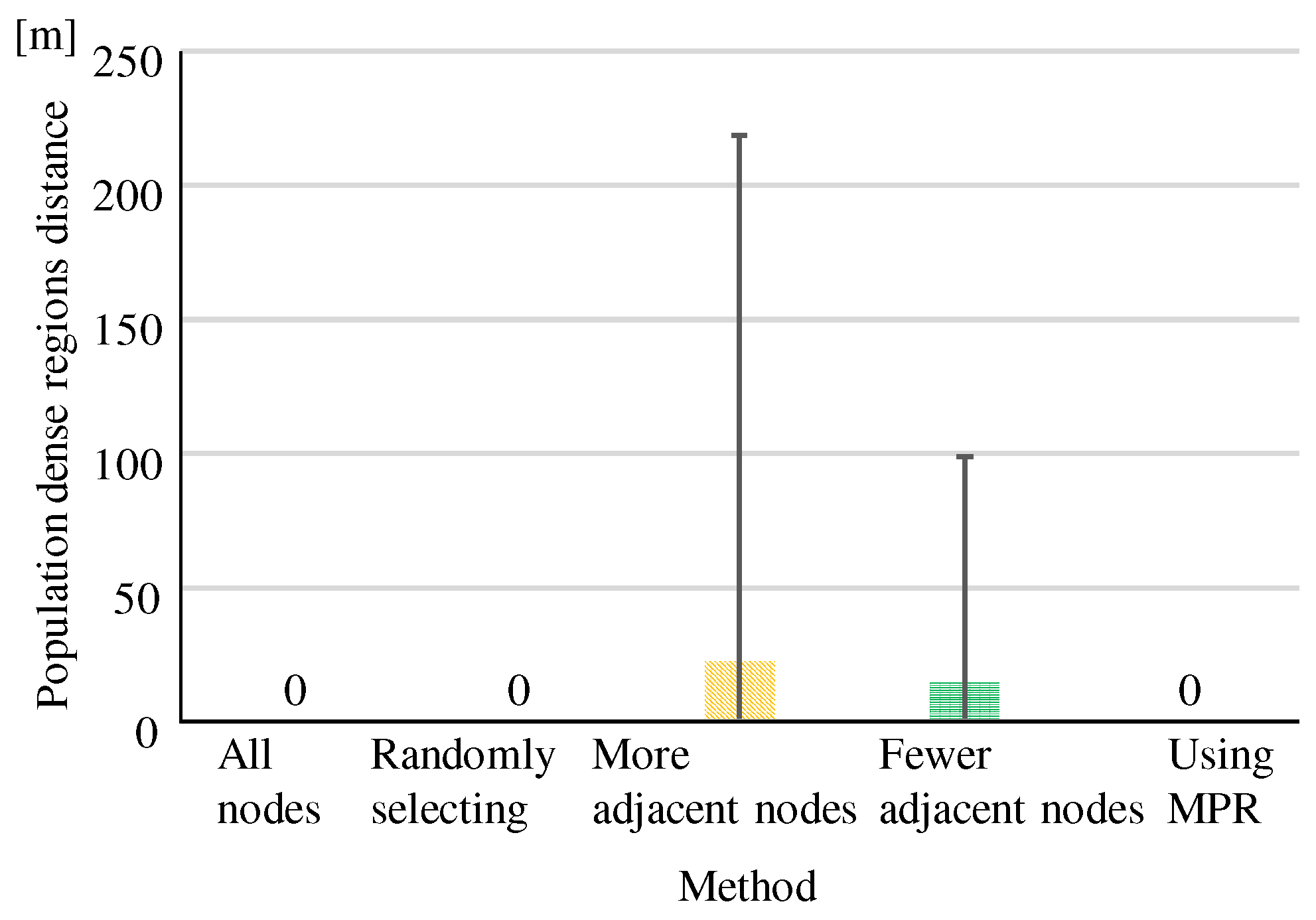
Population-Dense Regions Distance
6.3.3. Route Conflicts Ratio at Relay Nodes Density
7. Conclusions
Author Contributions
Funding
Data Availability Statement
Acknowledgments
Conflicts of Interest
References
- Valeska, E.; Evy, R.; Lieselot, V.; Philippe, L. Autonomous Delivery Solutions for Last-Mile Logistics Operations. Sustainability 2023, 15, 2774. [Google Scholar] [CrossRef]
- Amer, J.; Emil, P.; Mazen, B.; Robin, H.; Per, H. Drones in last-mile delivery: A systematic literature review from a logistics management perspective. Int. J. Logist. Manag. 2024. [Google Scholar] [CrossRef]
- Francesco, B.S. UAV-Based Delivery Systems: A Systematic Review, Current Trends, and Research Challenges. J. Auton. Transp. Syst. 2024, 1, 1–40. [Google Scholar]
- Kaneko, S.; Martins, J.R. Fleet Design Optimization of Package Delivery UAVs Considering Energy Consumption. In Proceedings of the AIAA SCITECH 2022 Forum, San Diego, CA, USA, 3–7 January 2022. [Google Scholar]
- Burke, C.; Nguyen, H.; Magilligan, M.; Noorani, R. Study of A Drone’s Payload Delivery Capabilities Utilizing Rotational Movement. In Proceedings of the 2019 International Conference on Robotics, Electrical and Signal Processing Techniques (ICREST), Dhaka, Bangladesh, 10–12 January 2019. [Google Scholar]
- Patchou, M.; Sliwa, B.; Wietfeld, C. Unmanned Aerial Vehicles in Logistics: Efficiency Gains and Communication Performance of Hybrid Combinations of Ground and Aerial Vehicles. In Proceedings of the 2019 IEEE Vehicular Networking Conference (VNC), Los Angeles, CA, USA, 4–6 December 2019. [Google Scholar]
- Dissanayaka, D.; Wanasinghe, R.T.; Silva, D.O.; Jayasiri, A.; Mann, K.I.G. Review of Navigation Methods for UAV-Based Parcel Delivery. IEEE Trans. Autom. Sci. Eng. 2024, 21, 1068–1082. [Google Scholar]
- Chen, S.; Chen, H.; Chang, C.W.; Wen, C.Y. Multilayer Mapping Kit for Autonomous UAV Navigation. IEEE Access 2021, 9, 31493–31503. [Google Scholar] [CrossRef]
- Rakesh, S.; Rojeena, B.; Shiho, K. 6G Enabled UAV Traffic Management: A Perspective. IEEE Access 2021, 9, 91119–91136. [Google Scholar]
- Abdeljawed, S.; Jalel, E.; Patrick, S. Vehicle Routing with Multiple UAVs for the Last-Mile Logistics Distribution Problem: Hybrid Distributed Optimization; Springer Nature: Berlin/Heidelberg, Germany, 2024. [Google Scholar]
- Hao, Z.; Lihua, D.; Chunxiao, C.; Bin, X. Three-Dimensional Unmanned Aerial Vehicle Route Planning Using Hybrid Differential Evolution. J. Adv. Comput. Intell. Intell. Inform. 2020, 24, 820–828. [Google Scholar]
- Yang, P.; Tang, K.; Lozano, J.A.; Cao, X. Path planning for single unmanned aerial vehicle by separately evolving waypoints. IEEE Trans. Robot. 2015, 31, 1130–1146. [Google Scholar] [CrossRef]
- Huang, C.; Fei, J.Y. UAV Path Planning Based on Particle Swarm Optimization with Global Best Path Competition. Int. J. Pattern Recognit. Artif. Intell. 2018, 32, 6. [Google Scholar] [CrossRef]
- Roberge, V.; Tarbouchi, M.; Labonté, G. Fast Genetic Algorithm Path Planner for Fixed-Wing Military UAV Using GPU. IEEE Trans. Aerosp. Electron. Syst. 2018, 54, 2105–2117. [Google Scholar] [CrossRef]
- Chen, Y.; Mei, Y.; Yu, J.; Su, X.; Xu, N. Three-dimensional unmanned aerial vehicle path planning using modified wolf pack search algorithm. Neurocomputing 2017, 266, 445–457. [Google Scholar]
- Yu, L.; Zhou, K. A dynamic local path planning method for outdoor robot based on characteristics extraction of laser rangefinder and extended support vector machine. Int. J. Pattern Recognit. Artif. Intell. 2016, 30, 1–23. [Google Scholar] [CrossRef]
- Wang, G.G.; Chu, H.C.E.; Mirjalili, S. Three-dimensional path planning for UCAV using an improved bat algorithm. Aerosp. Sci. Technol. 2016, 49, 231–238. [Google Scholar] [CrossRef]
- Gautam, S.A.; Verma, N. Path Planning for Unmanned Aerial Vehicle Based on Genetic Algorithm and Artificial Neural Network in 3D. In Proceedings of the 2014 International Conference on Data Mining and Intelligent Computing, Delhi, India, 5–6 September 2014; pp. 1–5. [Google Scholar]
- Goncharenko, V.I.; Dzekalo, A.A. The Algorithm for Constructing the UAV Route Based on the Combined Method. In Proceedings of the 2023 7th International Conference on Information, Control, and Communication Technologies (ICCT), Astrakhan, Russia, 2–6 October 2023; pp. 2–6. [Google Scholar]
- Ozlem, S.M. Optimum Arrival Routes for Flight Efficiency. J. Power Energy Eng. 2015, 3, 449–452. [Google Scholar]
- Schouwenaars, T.; Moor, B.D.; Feron, E.; How, J. Mixed integer programming for multi-vehicle path planning. In Proceedings of the 2001 European Control Conference (ECC), Karlsruhe, Germany, 4–7 September 2001; pp. 2603–2608. [Google Scholar]
- Evdokimenkov, V.N.; Krasilshchikov, M.N.; Kozorez, D.A. Development of pre-flight planning algorithms for the functional-program prototype of a distributed intellectual control system of unmanned flying vehicle groups. INCAS Bull. 2019, 11, 75–88. [Google Scholar] [CrossRef]
- Ramesh, A.; Suseendhar, P.; Venugopal, E.; Sivakumar, P. An Overview of Navigation Algorithms for Unmanned Aerial Vehicle. In Proceedings of the 2023 International Conference on Intelligent Data Communication Technologies and Internet of Things (IDCIoT), Bengaluru, India, 5–7 January 2023. [Google Scholar]
- Sivakumar, M.; Malleswari, N. A Literature Survey of Unmanned Aerial Vehicle Usage for Civil Applications. J. Aerosp. Technol. Manag. 2021, 13, e4021. [Google Scholar] [CrossRef]
- Fu, Z.; Yu, J.; Xie, G.; Chen, Y.; Mao, Y. A heuristic evolutionary algorithm of UAV path planning. Wirel. Commun. Mob. Comput. 2018, 2018, 2851964. [Google Scholar] [CrossRef]
- Danancier, K.; Ruvio, D.; Sung, I.; Nielsen, P. Comparison of path planning algorithms for an unmanned aerial vehicle deployment under threats. IFAC-PapersOnLine 2019, 52, 1978–1983. [Google Scholar] [CrossRef]
- Hodge, V.J.; Hawkins, R.; Alexander, R. Deep reinforcement learning for drone navigation using sensor data. Neural Comput. Appl. 2020, 36, 2015–2033. [Google Scholar] [CrossRef]
- GBN—Very High Frequency Omni-Directional Range (VOR), Federal Aviation Administration (FAA) United States Department of Transportation. Available online: https://www.faa.gov/about/office_org/headquarters_offices/ato/service_units/techops/navservices/gbng/vor (accessed on 1 January 2025).
- NAVIGATION AIDS/SYSTEMS, Federal Aviation Administration (FAA) United States Department of Transportation. Available online: https://www.faa.gov/air_traffic/publications/atpubs/aim_html/chap1_section_1.html (accessed on 1 January 2025).
- Gungor, V.C.; Lu, B.; Hancke, G.P. Opportunities and Challenges of Wireless Sensor Networks in Smart Grid. IEEE Trans. Ind. Electron. 2010, 57, 3557–3564. [Google Scholar] [CrossRef]
- Ueda, K.; Miyoshi, T. Autonomous Navigation Control of UAV Using Radio Smart Meter Devices. J. Telecommun. Inf. Technol. 2019, 2, 64–72. [Google Scholar]
- Corson, S.; Macker, J. Mobile Ad Hoc Networking (MANET): Routing Protocol Performance Issues and Evaluation Considerations, IETF, Network Working Group, RFC2501, January 1999. Available online: https://www.rfc-editor.org/rfc/rfc2501 (accessed on 1 January 2025).
- Clausen, T.H.; Jacquet, P. Optimized Link State Routing Protocol (OLSR), IETF, Network Working Group, RFC3626, October 2003. Available online: https://datatracker.ietf.org/doc/html/rfc3626 (accessed on 1 January 2025).
- Perkins, C.E.; B-Royer, E.M.; Das, S.R. Ad Hoc On-Demand Distance Vector (AODV) Routing, IETF, Network Working Group, RFC3561, July 2003. Available online: https://datatracker.ietf.org/doc/html/rfc3561 (accessed on 1 January 2025).
- Yang, Y.; Khalife, J.; Morales, J.J.; Kassas, Z.M. UAV Waypoint Opportunistic Navigation in GNSS-Denied Environments. IEEE Trans. Aerosp. Electron. Syst. 2022, 58, 663–678. [Google Scholar] [CrossRef]
- Yao, P.; Wang, H.; Su, Z. Real-time path planning of unmanned aerial vehicle for target tracking and obstacle avoidance in complex dynamic environment. Aerosp. Sci. Technol. 2015, 47, 269–279. [Google Scholar] [CrossRef]
- Gunji, H.; Yamazaki, T.; Yamamoto, R.; Miyoshi, T.; Ueda, K. Proactive Route Construction for UAV Delivery considering Distance and Safety using Wireless Multi-hop Network. IEICE Commun. Exp. 2022, 11, 411–416. [Google Scholar] [CrossRef]
- Kokubun, Y.; Yamazaki, T.; Yamamoto, R.; Miyoshi, T.; Ueda, K. Reactive Route Construction for UAV Delivery considering Travel Time and Safety using Wireless Multi-hop Network. IEICE Commun. Exp. 2022, 11, 405–410. [Google Scholar] [CrossRef]
- Zheng, Y.; Wang, Y.; Li, Z.; Dong, L.; Jiang, Y.; Zhang, H. A Mobility and Load Aware OLSR Routing Protocol for UAV Mobile Ad-Hoc Networks. In Proceedings of the 2014 International Conference on Information and Communications Technologies (ICT 2014), Nanjing, China, 15–17 May 2014. [Google Scholar]
- Dijkstra, E.W. A note on two problems in connexion with graphs. Numer. Math. 1959, 1, 269–271. [Google Scholar] [CrossRef]
- Larry, L.P.; Bruce, S.D. Computer Networks: A System Approach, 6th ed.; Morgan Kaufmann: Burlington, MA, USA, 2021; pp. 295–298. [Google Scholar]
- Jiang, M.; Li, J.; Tay, Y.C. Cluster Based Routing Protocol (CBRP) Functional Specification, IETF, INTERNET-DRAFT Retrieved 6, August 2018. Available online: https://datatracker.ietf.org/doc/html/draft-ietf-manet-cbrp-spec-01 (accessed on 1 January 2025).
- Jiang, M. CBRP: A Cluster-Based Routing Protocol for Mobile Ad Hoc Networks. October 2018. Available online: https://www.slideshare.net/slideshow/cbrp/118567872 (accessed on 22 August 2024).
- Narumi, H.; Shiraishi, Y.; Takahashi, O. A Reliable Cluster-Based Routing Algorithm for MANET. Doctoral Dissertation, Future University Hakodate, Hakodate, Japan, 2009; pp. 44–51. [Google Scholar]
- Heinzelman, W.R.; Chandrakasan, A.; Balakrishnan, H. Energy-Efficient Communication Protocol for Wireless Microsensor Networks. In Proceedings of the 33rd Annual Hawaii International Conference on System Sciences, Maui, HL, USA, 4–7 January 2000; pp. 1–10. [Google Scholar]
- Tandel, R.I. Leach Protocol in Wireless Sensor Network: A Survey. Int. J. Comput. Sci. Inf. Technol. 2016, 7, 1894–1896. [Google Scholar]
- Zhao, L.; Qu, S.; Yi, Y. A modified cluster-head selection algorithm in wireless sensor networks based on LEACH. J. Wireless Com. Netw. 2018, 287. [Google Scholar] [CrossRef]
- Mody, S.; Mirkar, S.; Ghag, R.; Kotecha, P. Cluster Head Selection Algorithm For Wireless Sensor Networks Using Machine Learning. In Proceedings of the 2021 International Conference on Computational Performance Evaluation (ComPE), Virtual, 1–3 December 2021. [Google Scholar]
- Baradaran, A.; Navi, K. HQCA-WSN: High-quality clustering algorithm and optimal cluster head selection using fuzzy logic in wireless sensor networks. Fuzzy Sets Syst. 2020, 389, 114–144. [Google Scholar] [CrossRef]
- Liu, X. Atypical hierarchical routing protocols for wireless sensor networks: A review. IEEE Sens. J. 2015, 15, 5372–5383. [Google Scholar] [CrossRef]
- Abbasi, A.A.; Younis, M. A survey on clustering algorithms for wireless sensor networks. Comput. Commun. 2007, 30, 2826–2841. [Google Scholar] [CrossRef]
- Fujii, K.; Sasaki, T.; Nakano, H.; Utani, A.; Miyauchi, A.; Yamamoto, H. A relay sensor node selection scheme in wireless sensor networks using a chaotic neural network. Int. Sympo. Nonlinear Theory Its Appl. 2010, 44, 390–393. [Google Scholar]
- Bruckner, D.; Picus, C.; Velik, R.; Herzner, W.; Zucker, G. Hierarchical semantic processing architecture for smart sensors in surveillance networks. IEEE Trans. Ind. Inform. 2012, 8, 291–301. [Google Scholar] [CrossRef]
- LoBello, L.; Toscano, E. An adaptive approach to topology management in large and dense real-time wireless sensor networks. IEEE Trans. Ind. Inform. 2009, 5, 314–324. [Google Scholar] [CrossRef]
- Kim, H.; Fujii, T.; Umebayashi, K. Relay Nodes Selection Using Reinforcement Learning. In Proceedings of the 2021 International Conference on Artificial Intelligence in Information and Communication (ICAIIC), Jeju, Republic of Korea, 13–16 April 2021. [Google Scholar]
- Menglei, J.; Qixun, Z.; Zhiyong, F.; Zhu, H.; Wei, L. Mobility Prediction Based Virtual Routing for Ad Hoc UAV Network. In Proceedings of the 2019 IEEE Global Communications Conference (GLOBECOM), Waikoloa, HI, USA, 9–13 December 2019. [Google Scholar]
- Yitao, L.; Ruiheng, W.; Lu, G.; Peng, H. Development of an Effective Relay Communication Technique for Multi-UAV Wireless Network. IEEE Access 2024, 12, 74087–74095. [Google Scholar]
- Ding, R.; Chen, J.; Wu, W.; Liu, J.; Gao, F.; Shen, X. Packet Routing in Dynamic Multi-Hop UAV Relay Network: A Multi-Agent Learning Approach. IEEE Trans. Veh. Technol. 2022, 71, 10059–10072. [Google Scholar] [CrossRef]
- ns-3 Network Simulator. Available online: https://www.nsnam.org/ (accessed on 10 June 2024).


| Relay Node Density [/km2] | Model Size [km2] | Applicable Experiments Eval. 1 to 4 |
|---|---|---|
| 12 km km | Eval. 4 | |
| 11 km km | Eval. 4 | |
| km km | Eval. 4 | |
| 10 km km | Eval. 1–4 | |
| 9 km km | Eval. 1–4 | |
| 8 km km | Eval. 1–3 | |
| 7 km km | Eval. 1–3 | |
| 6 km km | Eval. 1–4 |
Disclaimer/Publisher’s Note: The statements, opinions and data contained in all publications are solely those of the individual author(s) and contributor(s) and not of MDPI and/or the editor(s). MDPI and/or the editor(s) disclaim responsibility for any injury to people or property resulting from any ideas, methods, instructions or products referred to in the content. |
© 2025 by the authors. Licensee MDPI, Basel, Switzerland. This article is an open access article distributed under the terms and conditions of the Creative Commons Attribution (CC BY) license (https://creativecommons.org/licenses/by/4.0/).
Share and Cite
Ohkawa, S.; Ueda, K.; Miyoshi, T.; Yamazaki, T.; Yamamoto, R.; Funabiki, N. Relay Node Selection Methods for UAV Navigation Route Constructions in Wireless Multi-Hop Network Using Smart Meter Devices. Information 2025, 16, 22. https://doi.org/10.3390/info16010022
Ohkawa S, Ueda K, Miyoshi T, Yamazaki T, Yamamoto R, Funabiki N. Relay Node Selection Methods for UAV Navigation Route Constructions in Wireless Multi-Hop Network Using Smart Meter Devices. Information. 2025; 16(1):22. https://doi.org/10.3390/info16010022
Chicago/Turabian StyleOhkawa, Shuto, Kiyoshi Ueda, Takumi Miyoshi, Taku Yamazaki, Ryo Yamamoto, and Nobuo Funabiki. 2025. "Relay Node Selection Methods for UAV Navigation Route Constructions in Wireless Multi-Hop Network Using Smart Meter Devices" Information 16, no. 1: 22. https://doi.org/10.3390/info16010022
APA StyleOhkawa, S., Ueda, K., Miyoshi, T., Yamazaki, T., Yamamoto, R., & Funabiki, N. (2025). Relay Node Selection Methods for UAV Navigation Route Constructions in Wireless Multi-Hop Network Using Smart Meter Devices. Information, 16(1), 22. https://doi.org/10.3390/info16010022