Article

Multi-Beam Radar Communication Integrated System Design

School of Electronic and Information Engineering, Beijing Jiaotong University, Beijing 100044, China
*
Author to whom correspondence should be addressed.
Information 2023, 14(10), 566; https://doi.org/10.3390/info14100566
Submission received: 12 September 2023 / Revised: 10 October 2023 / Accepted: 13 October 2023 / Published: 14 October 2023
(This article belongs to the Section Wireless Technologies)

Abstract

:
In this paper, we propose a multi-beam integrated radar and communication scheme using phased-array antenna, in which the same LFM-BPSK integrated waveform is used for both the radar and the communication beams. In the integrated beam design, the radar beam is periodically scanned in different directions for detection, and the communication beam is periodically manipulated in one direction for communication. The system’s beamforming uses adaptive beamforming technology to achieve radar echoes and communication reception. For the LFM-BPSK integrated waveform used by the system, we propose a method for estimating parameters during communication reception. Through simulation, the proposed beam-pattern design, adaptive beamforming, and parameter estimation scheme can achieve radar and communication functions using phased-array antennas.

1. Introduction

The increasing scarcity of spectrum resources has gradually become an important issue in the development of modern wireless communication technology with the advent of 5G and the dramatic increase in wireless communication terminals [1,2,3]. In this application environment of scarce spectrum resources, the study of reusing existing spectrum resources has become a hotspot of current research. Radar communication integration technology is an important research area for reusing the existing wireless spectrum. Radar and wireless communication technology belong to the important field of radio technology application. Although their use of the spectrum gradually overlaps, the two have undergone a long period of independent development. As a result, their technical indicators are in a state of mutual fragmentation. Each technology consumes a large amount of spectrum resources, energy resources, and space resources individually. With the progress of wireless technology, the miniaturisation and high-frequency development of radar and communication have led to the convergence of their hardware architecture, signal processing mode, and antenna array development mode [4,5]. The primary technical approach to integrating radar communication technology can be summarised as follows: (1) Module coexistence mechanism: radar and communication utilise distinct spectrum resources and temporal domains, share local hardware resources, and possess different waveforms and transceiver mechanisms. The critical technologies encompass time domain allocation, signal transmitting, and power allocation. (2) Spectrum-sharing mechanism: Radar and communication share the same spectrum resources but use sesidete hardware resources. Each design corresponds waveforms for radar detection and communication in the common time domain or airspace, while minimizing interference between the two. Key technologies include pre-coding design, receive anti-interference design, and dual-signal sesidetion at the receiving end. (3) The complete integration mechanism utilizes the same hardware resources, spectrum resources, and waveform design for both radar and communication. There is no distinction between the two in terms of the time and frequency domains. The integration technology eliminates mutual interference and dual signal sesidetion, allowing the received signal to be considered as both a radar detection signal and a communication signal. The key technologies involved are integrated system waveform and beam-pattern design, as well as integrated communication receiver design. The complete integration of radar communication represents the main direction for the development of radar communication integration.
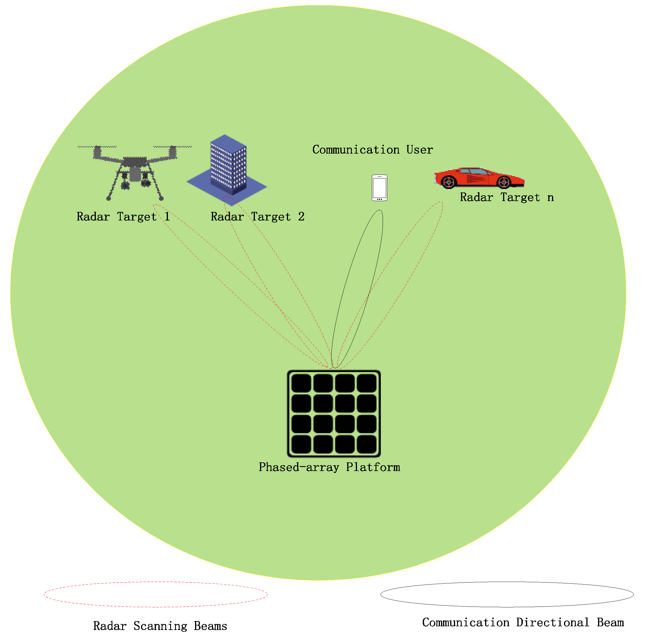
Phased-array radar is currently the mainstream technology in radar systems, which enables multiple beam directions and intensities for radar detection. This technology is free from mechanical inertia constraints, resulting in significantly improved scanning speeds. Moreover, its beam control is both flexible and user-friendly, making it a widely adopted modern radar technology. Phased-array radar has the capability to scan a full range of airspace. In the field of radar communication integration technology, while the integration of waveforms for single antennas is mature, using mechanical scanning radar to achieve integration function leads to a lower communication efficiency and limited scanning speed, along with the shortcoming of communication and radar function in the same direction. In comparison, phased-array radar has several advantages, including a flexible beam design, a wide range of use, and the controllability of the side lobe power. It also has the ability to achieve multiple beams simultaneously for both radar and communication functions. This paper aims to utilize phased-array radar as the hardware basis to achieve an integrated system for beam-pattern design. The system function schematic diagram is shown in Figure 1.
The design of beams for phased-array antennas is a well-established research field. The fundamental principle utilises the phased-array feed network during transmission to achieve a distortion-free beam in the desired direction while simultaneously suppressing the side lobe power of the beam. The aim is to eliminate clutter interference in undesired directions during the beamforming, and to design for zero sagging in directions of interference and undesired directions. The CVX optimisation toolbox was utilised in the literature [6] to minimise the peak of the side-lobe level when designing the beam pattern for beam formation in phased-array radar. Study [7] presented an adaptive beam synthesis technique for producing a phased-array radar beam that can alter its direction as the interference direction shifts. Study [8] presents a method for synthesising beams in reconfigurable arrays with two-dimensional geometry, where the algorithm constrains the power of the array. The aforementioned techniques solely address diverse radar beam scenarios and are tailored towards beam-related use within the radar field. Study [9] presented a beam-fouling architecture for phased-MIMO hybrids. The architecture initially divides subarrays and distributes the realization of radar beams and communication beams. Orthogonal waveforms are sent between subarrays, while phased-array coherent signals are sent inside subarrays to achieve the performance trade-offs of phased arrays and multiple-input/multiple-output (MIMO) integer columns. Studies [10,11] investigated the technique of multiple beam commonality synthesis for phased-MIMO hybrid arrays. This technique enables the system to optimize both radar and communication beams simultaneously. Study [12] examined the methodology and effectiveness of quantification in multi-beam systems. A comparison of the characteristics of the different beam methods is shown in Table 1.
The aforementioned method [9,10,
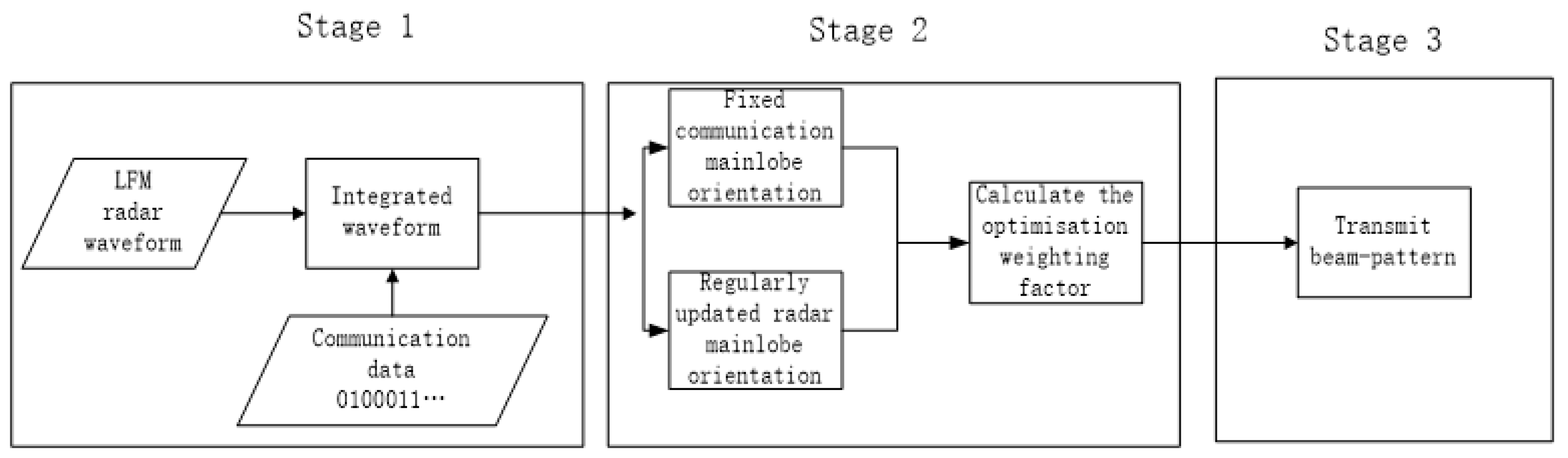
11] for integrated beams in phased-MIMO radar communication primarily capitalises on the MIMO radar’s high degree of freedom and the ease of implementing coherent signals in phased arrays. While it is easier to realise the beam direction within subarrays and to have different subarrays distribute radar and communication beams, meeting waveform orthogonality between subarrays increases engineering difficulty. Additionally, eliminating mutual interference between radar beams and communication beams must also be addressed. Aiming to tackle the aforementioned beam design issues, this paper presents a straightforward design approach for the beam direction transmitting/receiving beam pattern in a phased-array integrated system. Firstly, based on phased-array radar, the phased-array integrated system transmits the main radar signal and communication signal simultaneously, with the remaining area being defined as the side lobe. Secondly, the radar and communication main lobes’ direction, width, and power are designed. The integrated system’s reduction is then taken into account. Then, to decrease the influence of the beam’s side lobe as the objective function, one can create a convex optimization problem and use the convex optimization toolbox to solve it, and obtain the optimal weight matrix. Finally, the communication main lobe direction remains unchanged during the repeated transmission of the integrated waveform pulse. The communication data are updated, and the radar main lobe scanning direction is changed. This enables the integrated system to achieve directional communication and radar omni-directional detection at the same time. The transmit beam pattern method is shown in Figure 2.
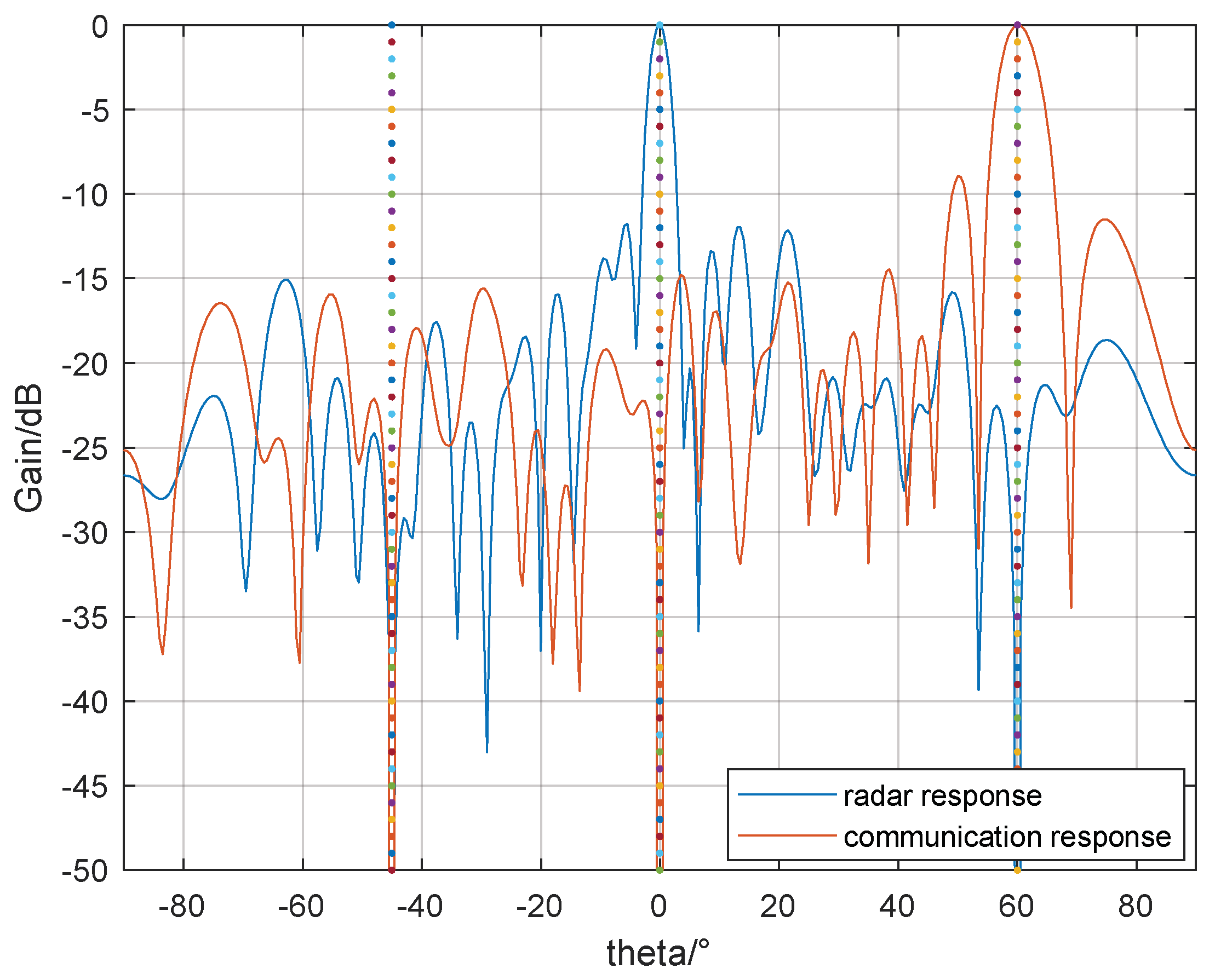
Beamforming is a key element of signal processing for an integrated system, allowing the integrated antenna array to receive signals in a specific direction and mitigate interference from other directions. Adaptive beamforming typically provides greater directivity and improved interference resistance compared to conventional beamforming. This paper utilises the well-established linear constrained minimum variance criterion (LCMV) adaptive beamforming to achieve radar signal and communication signal beamforming. Unlike the conventional multi-beam MIMO radar communication integration scheme, the phased-array integration system presented in this paper features both a radar transmission panel and a communication transmission panel, enabling detection and communication functions, respectively. When the signal is received, the beamforming technique implements target echo and duplex communication functions. Both the radar main and communication main lobe employ the same integrated waveform and carry the same communication data, with only the direction pointing and power differing. There is no interference between multiple beams, which significantly reduces the complexity of waveform design.
The integrated system for radar and communication in a phased array accomplishes simultaneous communication and radar detection using multiple beams. The radar detection function is similar to that of traditional phased-array radar, but the design and reception of an integrated waveform using the phased-array system is a challenging task. As the linear frequency modulation (LFM) radar waveform is a commonly used waveform, this paper focuses on the development and reception of the integrated waveform based on LFM. Through a comparison of integrated signals such as LFM-MSK, LFM-CPM, LFM-8PSK and LFM-BPSK, as proposed in the existing literature [13,14,15,16], the integrated waveform used in this paper is LFM-BPSK. This waveform considers both the great detection performance of the LFM radar waveform and the excellent communication performance of the BPSK. In prior analyses of the literature [13,14,15,16,17], greater emphasis has been given to the development and performance analysis of LFM-type integrated waveforms, with little consideration given to the demodulation process of the integrated waveform data that utilise LFM as the carrier. Since the LFM carrier shifts frequency over time, its collection of waveforms can be considered as a series of brief LFM waveform collections. Consequently, the data extraction approach for the LFM carrier varies from the regular carrier extraction data approach. The crucial technology relies on building segmented reference signals. When creating the segmented matched filter, its tuning frequency remains fixed, with the determination of the initial frequency information of the integrated waveform set being key to constructing the matched filter. In this paper, we present a set of judgements based on the fractional Fourier transform (FRFT) that can extract the initial frequency from the LFM-BPSK waveform set, and design the reference signal.
The main contributions of this paper are as follows:
(1)
A method for designing a beam pattern with integrated beamforming for phased-array radar communication is proposed. This method uses a phased-array antenna to generate both a radar scanning beam and a communication directional beam simultaneously. The radar beam’s scanning direction changes with each packet update, achieving both an omni-directional radar detection function and a directional communication function.
(2)
In the integrated beamforming scheme, LCMV adaptive beamforming is utilised to implement radar and communication functions. These functions are implemented, respectively, to form a null point in the undesired direction and to ensure better reception of the input signals in the intended direction.
(3)
For the integrated waveform LFM-BPSK, this paper proposes using FRFT to estimate the initial frequency and construct matched filtering in the receiver design to achieve the reception function of communication data. This approach enhances objectivity and clarity in the design of the communication system.
The paper is structured as follows: Section 1 provides an introduction, Section 2 outlines the model and scheme for the integrated system, Section 3 presents the initial frequency parameter estimation scheme for the integrated signal set, Section 4 describes the experiments and simulations to evaluate the estimation performance of the beam fouling and communication receiver, and Section 5 summarizes the characteristics of the integrated system.

2. Radar Communication Integration System Mode

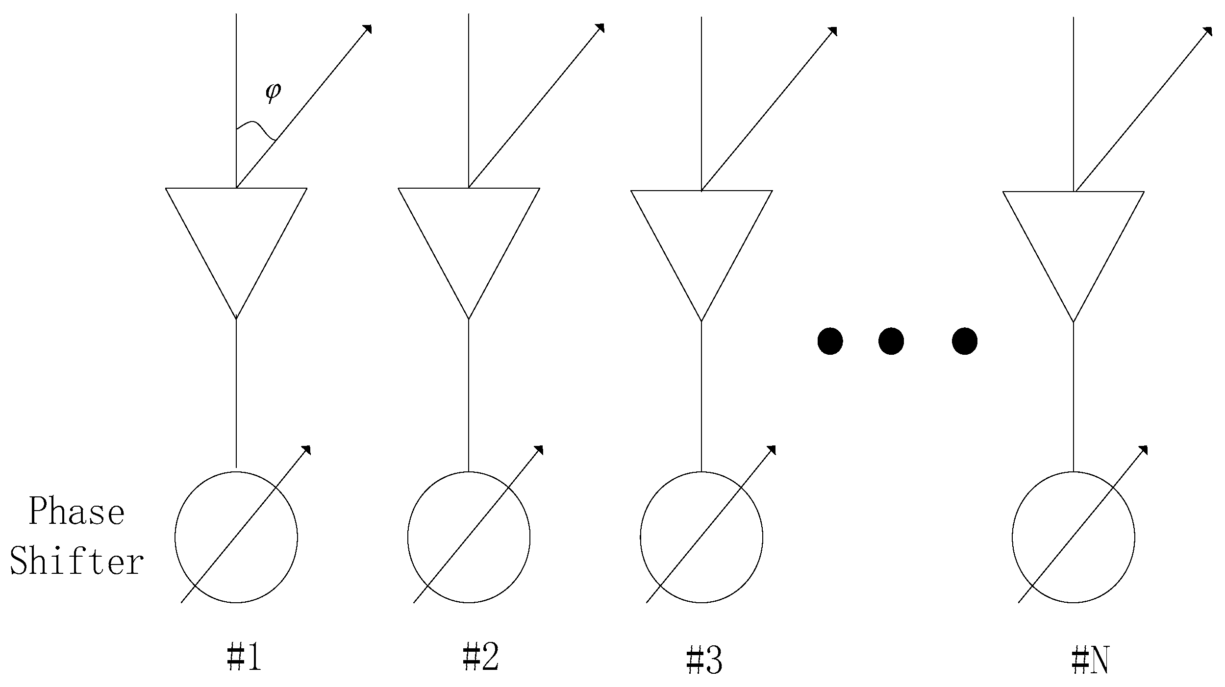
In this study, we utilise phased-array antenna technology, equipped with both transmitter and receiver modules on each array antenna, to attain the disseminated power transmission of the complete beam. The system utilises the phase shift scanning technique to alter the excitation phase of the array antenna. This results in achieving the optimal distribution of energy in space by controlling the pointing and intensity of different beams. The basic principle of the phased-array radar communication integration system can be simply analysed by analysing the principle of the array antenna. The phased-array integration system’s principle is depicted in Figure 3. It is assumed that N -array-element antennas combine to form a one-dimensional linear phase shifter antenna of the phased array. All array elements are non-directional, point radiation sources, and all the inputs’ array feeds are equal-amplitude and same-phase feed signals. The assumed phase shift of each phase shifter is 0, φ , 2 φ , 3 φ , etc. The N -element array antenna is uniformly linearly distributed with each array element, spaced by d , which is half-wavelength. The phase difference between the feeds of each neighbouring array element is φ .
In Figure 3, the φ angle indicates the deviation from the normal direction, and the field strength, E ( φ ) , at a test point in the far field can be expressed as the sum of the field strength vectors, E k , of each array element at that point in the direction of deviation, φ , from the normal. Then, the field strength at the test point can be expressed as follows:
E ( φ ) = E 1 + E 2 + E 3 + + E N = k = 1 N E k
In Equation (1), because all the array elements are fed with equal amplitude, the difference in the amplitude of each array element to the far-field point can be ignored, and it can be assumed that the amplitude of each array element fed to the point is equal, which is expressed by the symbol E . Then, if we take the phase of the radiated field phase of the no. 1 array element as the reference phase, E 1 , combined with the phase difference of each array element, the field strength at the test point can be rewritten as
E ( φ ) = E k = 1 N exp [ j k ( ψ φ ) ]
In Equation (2), ψ = 2 π λ d sin φ is the phase difference in radiation of neighbouring array elements caused by the wave range difference, φ is the phase difference of neighbouring phases, k ψ is the phase precession of E k and E 1 , and k φ is the phase lag of E k and E 1 . In the antenna array element, the phase difference of the radiated fields of the neighbouring array elements is φ φ 1 . According to the isoperimetric summation and applying Yura’s formula, the vector sum at the test point can be written as
E ( φ ) = E sin [ N 2 ( ψ φ ) ] sin [ 1 2 ( ψ φ ) ] e j [ N 2 ( ψ φ ) ]
In Equation (3), when the phase difference is ψ = φ , neighbouring array elements are cancelled by the phase difference of the wave range, the components are summed in the same phase, and the radiation intensity at the test point in the far field is at the maximum, which is
E ( φ ) max = N E
So, the normalised direction diagram of the array antenna can be expressed as
F ( φ ) = E ( φ ) E ( φ ) max = sin [ N 2 ( ψ φ ) ] N sin [ 1 2 ( ψ φ ) ] = sin [ N 2 ( 2 π λ d sin θ φ ) ] N sin [ 1 2 ( 2 π λ d sin θ φ ) ]
When the phase difference, φ , between the neighbouring array element is 0, the normal deviation angle, θ , is 0, on behalf of the array element’s equal-amplitude in-phase feed, at this time, F ( φ ) = 1 , that is, the maximum value of the direction in the beam pattern of the normal array element. If the phase difference is φ 0 , the maximum direction should be shifted, and the shift angle is determined by the phase shift, φ . By changing the phase shift, φ , the beam direction can be changed to achieve the beam synthesis of the uniform linear-array (ULA) antenna and achieve the purpose of phased-array radar wave-speed scanning.
On the basis of ULA, rectangular-array antennas, circular-array antennas, hexagonal-array antennas, random-array antennas and three-dimensional-array antennas, among other phased-array modes, have been developed. These can be flexibly applied to a variety of work situations. Although the beam-pattern expression of planar rectangular arrays and three-dimensional arrays differs from that of a ULA, its working principle and beam-pattern formula can be derived based on the ULA. However, this derivation is not described in detail within this paper. When the integrated system of phased-array radar communication is operational, the radiation unit of the array antenna is controlled to generate multiple beams in varying directions. This enables a multidirectional scanning, detection, and communication capability. Additionally, the power output of the multiple beams can be adjusted in real time, and flexible function switching is possible within the airspace range.

2.1. Design of Integrated Transmit Beam Pattern

The design of the transmit beam pattern of the integrated system is one of the important research contents of the radar communication integrated system, which includes the design of the array antenna, the optimisation theory, and the transmission equation of the radar communication. In this paper, the designed radar communication integrated transmit beam-pattern technology, using phased-array radar antennas for the corresponding beam-sending direction. The system for transmit beam patterns features both a radar main lobe and a communication main lobe. Each main lobe sends an integrated waveform with both communication and radar detection capabilities. By adjusting the beam pointing and power intensity, the system achieves the simultaneous integration of radar and communication functions. The design method for conventional beam patterns suffers from significant fluctuations in the main and side lobes. This issue impedes the creation of the beam pattern for the integrated system. The approach implements restricted side lobes for improved design. To address this problem, this paper utilises the principles of the convex optimisation theory to develop a new beam design method.
Conventional radar antenna beam-pattern design typically employs the traditional side-lobe minimisation algorithm, which revolves around the principle of minimising the side lobe:
(1)
The direction of the main lobe of the beam pattern can be output without any distortion;
(2)
The side panel of the beam pattern that is external to the main lobe is intended to be level;
(3)
An optimisation process is employed to attain the reduction of the side-lobe level.
In this method, it is assumed that the coverage of the array antenna is A = θ min     θ max , the main lobe direction is θ m a i n , and the main lobe width is Δ m a i n . Then, the angle range of the main lobe of the whole beam pattern is A m a i n = θ m a i n 0.5 Δ m a i n   ,   θ m a i n + 0.5 Δ m a i n , and the range of the side lobe is A s i d e = θ min ,   θ m a i n 0.5 Δ m a i n θ m a i n + 0.5 Δ m a i n , θ max   .
The orientation vector of the array antenna is a ( θ ) , and the weighting vector of the beam pattern is w ; then, the design of the beam pattern of the array antenna can be modelled as a convex optimization problem:
min   max w H a ( θ s i d e )             θ s i d e A s i d e s . t . w H a ( θ m a i n ) = 1
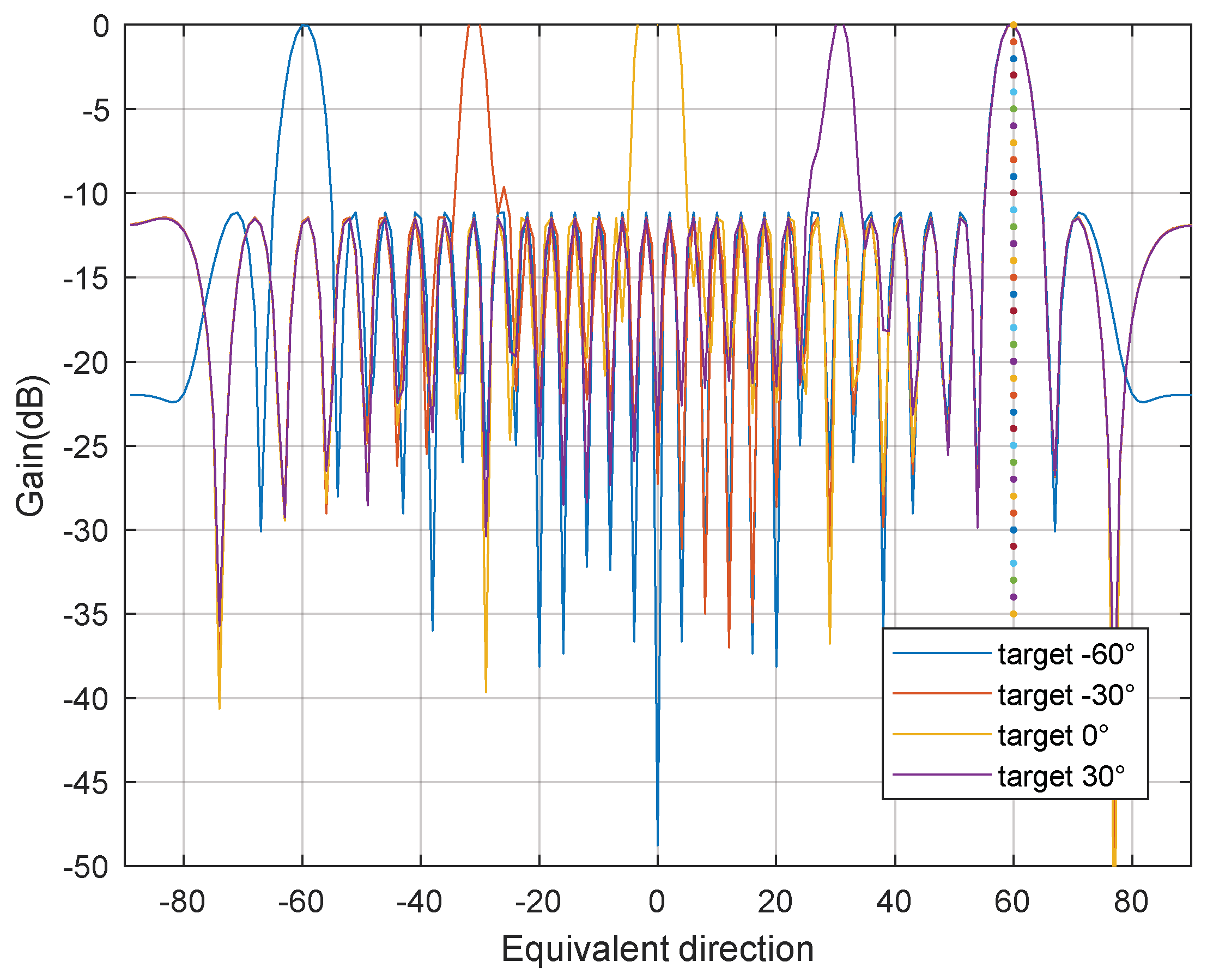
On the basis of the radar array beam emission direction, the integrated beam emission direction design steps in this paper are as follows: Firstly, the integrated transmit beam must be divided into the radar main lobe area and communication main lobe area within the airspace. From there, the width of both the radar and communication main lobes must be determined. It is important to ensure that neither the radar nor the communication main lobes have any distorted output. Finally, an optimisation problem can be formed by using the reduction of the side lobe in other areas as the objective function. Finally, the convex optimisation toolbox should be employed to solve for the globally optimal weight vector in the array beam synthesis. The biggest advantage of this method is that it uses only one convex optimisation theory, and it can take into account the direction of the radar main lobe and the communication main lobe on the basis of reducing the level of the side lobe.
The beam pattern for the main lobe and communication main lobe can be customized for beam synthesis by altering the quantity, width, and orientation of the communication main lobe, without compromising the radar main lobe’s beam-pattern accuracy.
In this integrated beam synthesis method, assuming that the coverage of the array antenna is A = θ min     θ max , the radar main lobe direction is θ m a i n , the main lobe width is Δ m a i n , the communication sub-lobe direction is θ c o m , and the communication sub-lobe width is Δ c o m ; then the angle range of the main lobe of the entire whole array is A m a i n = θ m a i n 0.5 Δ m a i n   ,   θ m a i n + 0.5 Δ m a i n , the communication sub-lobe range is A c o m = θ c o m 0.5 Δ c o m   ,   θ c o m + 0.5 Δ c o m , and the range of the rest of the side lobes is A s i d e = A A m a i n A c o m . The weighted vector of the direction is w , and the array guidance vector is a ( θ ) ; then, the design of the direction of the integrated system array antenna can be modelled as a convex optimization problem:
min   max w H a ( θ s i d e )             θ s i d e A s i d e s . t . w H a ( θ m a i n ) = 1 w H a ( θ c o m ) = α                                   θ c o m A c o m
In Equation (7), α is the power ratio of the communication main lobe and the radar main lobe, the range of values α [ 0 , 1 ] . In practical engineering applications, the number of communication main lobes can be single, or it can be more than one, and the power ratio coefficient, α , can also be adjusted to achieve different communication transmission power for different integration work occasions; this paper assumes that the ratio coefficient is 1.

2.2. Integrated System Adaptive Beamforming Design

When the integrated system antenna array is for signal reception, there is a need for the effective reception of useful signals. Effective reception includes two aspects: one is to make the main lobe of the array-receiving direction aligned with the desired signal direction; the second is to effectively suppress the interference signal. Adaptive beamforming technology is based on the combination of these two aspects of the gradual development of the application. In this paper, the more classical LCMV beamforming algorithm is used; if the arrival angle range of the desired signal is known, then the time delay compensation can be performed on the array-received data first, so that the array can maintain consistency in the reception of the desired signal. Then, constraints are imposed on the array coefficients in order to adaptively make the output of the beam’s former minimum energy E y ( t ) × y ( t ) for the received waveform, y ( t ) ; the minimum energy is equivalent to make the output signal that is not in the desired direction of the noise equivalent, in order to minimise the noise in the non-desired direction of the output signal, and thus achieving the purpose of enhancing the signal in the desired direction.
The constraints of the LCMV beamforming algorithm are
min w E y ( t ) = min w w H R w
In the above problem, R is the correlation matrix; we can use the Lagrange multiplier method to solve y ( t ) , so that the objective function becomes
L ( w ) = w H R w + λ [ w H a ( θ d ) 1 ]
In the above equation, λ is the optimisation coefficients, θ d is the direction of the wave, and the results are obtained by taking the derivatives of w on both sides of the equation:
L w = 2 R w + λ a ( θ d ) = 0
To obtain the optimal weight vector,
w o p t = u R 1 a ( θ d )
In the above expression of optimisation, u is the constant of proportionality; at this time, the antenna array only receives the signal from the desired direction of the wave and suppresses the signals from the other directions of the wave. When the beamforming algorithm can be fully realised, it is consistent with w H a ( θ d ) = 1 , which can be rewritten as a H ( θ d ) w = 1 , and then u can be expressed as
u = 1 a H ( θ d ) R 1 a ( θ d )
At this time, the best expression form of the weight vector is
w o p t = R 1 a ( θ d ) a H ( θ d ) R 1 a ( θ d )
From the optimal expression of the weight vector, it can be deduced that the optimal weight vector, w o p t , for beamforming depends on the desired wave direction of the array, independently of other factors.

2.3. Integrated Waveform Scheme

The integrated phased-array system performs both detection and communication functions. The transmitter emits an integrated waveform, creating a radar and communication beam in the system. The integrated transmitter receives the target echo from the radar beam, while the communication receiver receives the communication beam. The system’s integrated waveform should possess both detection and communication capabilities. The LFM signal is a frequently utilized radar signal. Embedding communication data based on the LFM signal is an effective method to create a radar communication integrated waveform. In the phased-array radar communication integrated system discussed in this paper, LFM-BPSK technology is utilised to achieve optimal radar detection and communication performance. The expression of conventional LFM is as follows:
s LFM ( t ) = A C h i r p exp   ( j ( 2 π f o t + j π u t 2 + Ω 0 ) ) ,                                               0 t T
where f o is the initial frequency, u is the frequency modulation, Ω 0 is the initial phase, and the simplified LFM waveform expression is
s LFM ( t ) = exp   ( j π u t 2 ) ,       0 t T
After a segment of LFM is embedded with a BPSK communication signal, the LFM-BPSK expression becomes
s LFM B P S K ( t ) = exp ( j π u t 2 + θ d a t a ( t ) ) ,
In Equation (16), θ d a t a ( t ) = θ ( t i T b ) [ ϕ , ϕ ] 0 where θ ( t ) represents a string of specific communication values; the value range θ ( t ) is [ π 2 , π 2 ] , representing the BPSK communication data.
In this paper, the phased-array system employs LFM-BPSK as the integration waveform for its integration function. With each repeated pulse frequency transmission, the communication beam direction remains constant while the communication data are updated. Meanwhile, the radar beam scanning direction changes. The integration system has a high-pulse repetition sending frequency, enabling the system to effectively perform high-speed radar omnidirectional detection and qualitative communication.

3. Parameter Estimation for Communication Receiver

The radar communication integrated signal can simultaneously achieve target detection and communication tasks. For the radar detection capabilities of the integrated system, previous studies within the literature [13,14,15,16,17] have conducted more thorough analyses. However, the communication reception performance of the LFM-based integrated signal has been largely overlooked. For the integrated waveform signal based on LFM, it can be considered as a distinct communication mode where the LFM functions as the carrier. This mode significantly differs from the conventional carrier communication mode. In traditional carrier communication, the frequency of the carrier signal remains constant, and the baseband communication information can be extracted using the de-carrier method, which has a well-established technical foundation. However, the LFM carrier frequency fluctuates over time during operation. In practical engineering applications, the LFM wave signal cannot be eliminated using the conventional carrier removal method, necessitating the consideration of an alternative approach for removing the LFM carrier. By analysing the ideas and expressions of the LFM-BPSK integrated waveform design, it is apparent that the information bits are embedded within various sub-pulses of the linear FM signal. The integrated signal can be considered as the combination of multiple brief linear FM signals, with each being a short linear FM signal that undergoes a change in initial frequency and a jump in phase information.
From the communication point of view, the integrated-signal LFM-BPSK-carrying N c bit can be regarded as the signal set of multiple micro-LFMs, with different initial frequencies, f i , different phase information, and the same frequency modulation with the same signal set expression:
s L F M B P S K ( t ) = i = 1 N c exp ( j 2 π f i t + j π u t 2 + j θ i ) .
Equation (17) can be regarded as a set of LFM waveform signals with different initial frequencies and different phases, but with the same tuning frequency, and the frequency modulation is known. Inspired by the literature [16,18,19], when receiving a sequence of LFM waveform set signals, the communication receiver must determine the initial frequency of the waveform set and create a segmented reference signal based on both the initial frequency and the tuning frequency. It is assumed that the communication receiver is located in the far-field of the radar transceiver and comprises a single receive element. The received signal at the communication receiver is a time delay, τ , of the transmitted signal, as follows:
s L F M B P S K ( t τ ) = i = 1 N c exp ( j 2 π f i ( t τ ) + j π u ( t τ ) 2 + j θ i ) .
Assuming that the delay, τ , can be estimated in directional communication. By utilizing the estimated parameters, the reference signal at the receiving end of the communication can be expressed as
r e f L F M B P S K ( t ) = i = 1 N c exp ( j 2 π f i ( t τ ) + j π u ( t τ ) 2 ) .
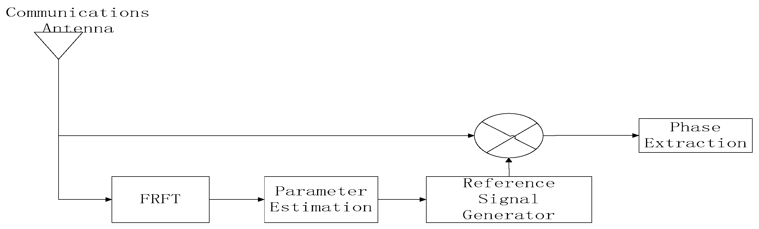
The communication code element value be accurately determined as
y ( t ) = s L F M B P S K ( t τ ) r e f L F M B P S K c ( t ) d τ .
( ) c stands for the complex conjugate. Thus, estimating the initial frequency parameter of the integrated waveform set is crucial to the communication receiver design. The schematic diagram of the communication receiver is shown in Figure 4.
The FRFT provides the signal’s Fourier transform representation in the time–frequency plane. It is formed by rotating the coordinate axis anti-clockwise from the origin through any angle [20]. The FRFT is a time–frequency analysis method that provides information on a signal’s time and frequency domains. It is particularly effective in the analysis of LFM signals due to its superior aggregation capabilities. In the literature [21], FRFT was used to study the LFM signal set, and it was found that the LFM, at a certain level, is a shock function, and the FRFT approach was then used to extract the relevant data. In the literature [22], the FRFT properties of the LFM signal set were analysed, and multi-parameter data for the set were extracted using the FRFT method with varying initial frequencies. In this paper the p -order FRFT of the signal x ( t ) is defined as:
X p ( u ) = F p [ x ] ( u ) = + x ( t ) K p ( t , u ) d u
In Equation (18), F p is the FRFT transform operator and K p ( t , u ) is the kernel function, which is defined and expressed as
K p ( t , u ) = A α exp [ i ( t 2 cot α 2 u t csc α + u 2 cot α 2 ) ] , α n π δ ( t u ) ,                                                                                         α = 2 n π δ ( t + u ) ,                                                                                         α = ( 2 n ± 1 ) π
In Equation (19), A α = ( 1 i cot α ) / 2 π , α represents the rotation angle of the time–frequency plane, and u represents the modulation frequency. From the FRFT of the signal, it can be seen that the decomposition basis function of the FRFT of the signal is transformed from a single-frequency sinusoidal signal with conventional Fourier transform to an LFM signal. The standard LFM signal is represented as follows:
s L F M ( t ) = A o exp ( j 2 π f o + j π u o t 2 + j θ o )
The process of detection using FRFT for LFM signals can be expressed using the following equation:
{ α o , u o } = arg max α , u X α ( u ) 2
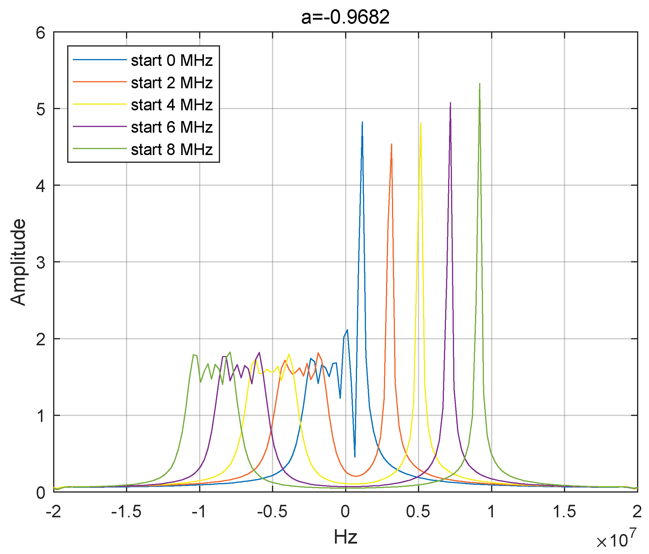
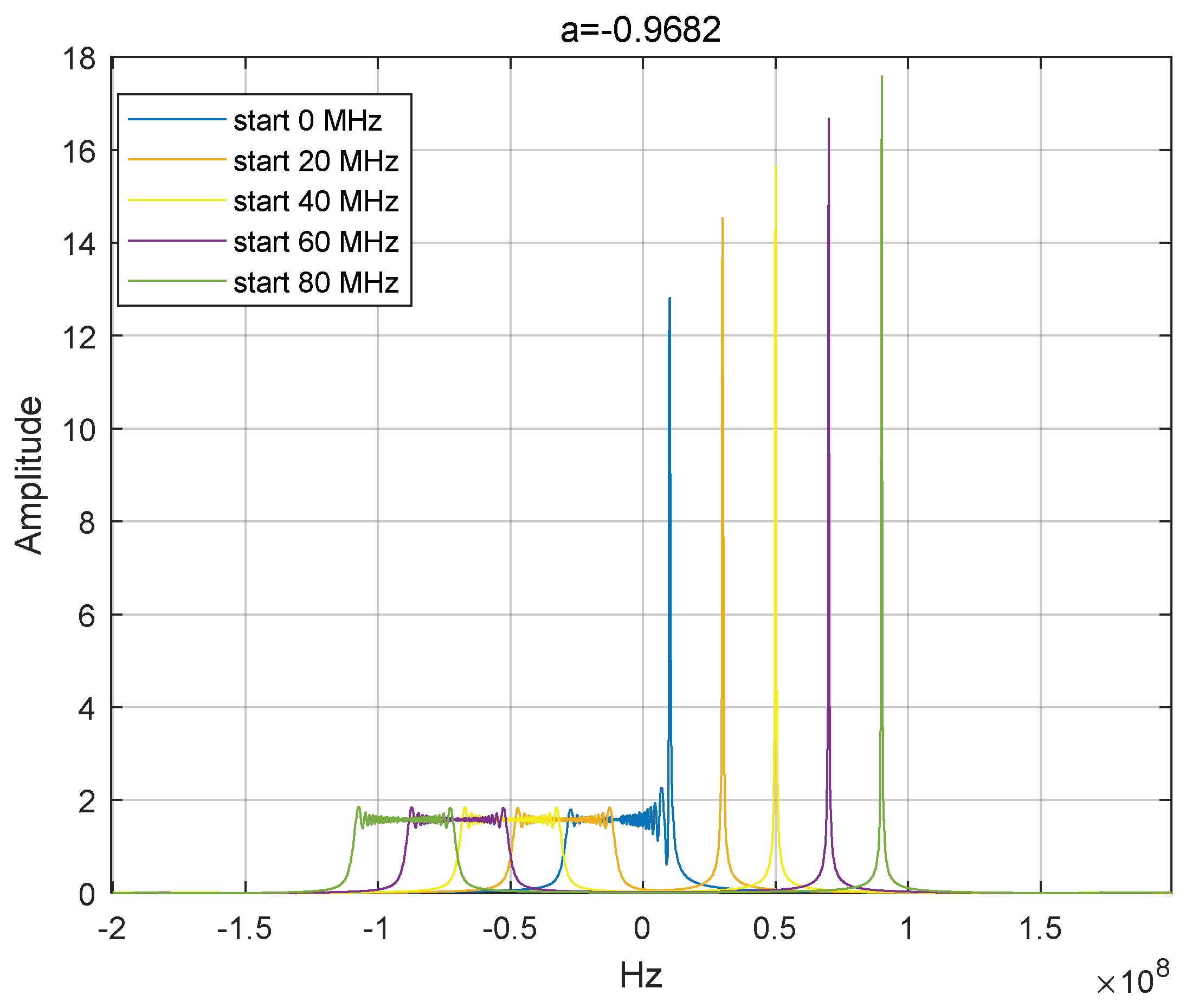
The result of the specific parameter of the initial frequency, f o , is shown in the following equation:
f o = u csc α o
For the LFM waveform set, using FRFT to estimate the initial frequency is a mature technique to estimate the initial frequency of the waveform set at the communication receiver in this paper. After determining the initial frequency of the integrated waveform set, a reference signal can be constructed according to the tuning frequency and initial frequency, multiplied with the corresponding set of received signals, and judged to be extracted to obtain the phase information, θ i , which can then be converted into binary communication symbols, so as to obtain the communication data.

4. Simulation

This chapter examines the simulation of the beam direction of the integrated system and the initial frequency estimation of the waveform set at the receiving end of communication. The performance of the beam direction map is explored primarily under the one-dimensional uniform array element arrangement method. Table 2 displays the simulation parameters of the beam transmit/receive direction for the integrated system.
The transmit/receive directional beam pattern system described in this paper uses a convex optimisation algorithm to calculate the weight vectors, w , which are correlated only with the main lobes of the radar and communication systems. In engineering applications, the communication main lobe direction remains fixed, while the radar main lobe is periodically scanned within a specific range of directions. The scanning range is divided into intervals, and weight coefficients are pre-calculated for the central direction of each interval. A limited set of weight coefficients is then stored in a data table for convenient searching during scanning, thus avoiding the need for online calculation. When the integrated system undertakes the reception task, the calculation of adaptive beam weights remains consistent with the traditional array signal processing method. To decrease the number of operations, chunked matrix inversion and other iterative algorithms may be implemented.
The analysis of the transmitting complexity when using the online convex optimisation method is the following: Based on (7), the calculation complexity of our integrated method mainly depends on the number of antenna, N , and the error tolerance, ε . Therefore, we utilise the interior point method to determine that the computational complexity of our emission direction map is O ( ln ( 1 / ε ) N 3 ) , given a fixed error tolerance, where the overall complexity is determined based on the N . The simulations within this paper utilise an error tolerance of ε = 1.49 × 10⁻⁸.

4.1. Transmit Beam Pattern

The integrated system uses a uniform ULA for single radar main lobe and single communication main lobe transmit beam direction design: the radar main lobe’s pointing changes with each integration pulse repetition, the scanning range is from −90° to 90°, and the general pulse repetition frequency (PRF) ensures that the radar main lobe scans quickly over the whole scanning area, thus realizing the radar communication integration function. When designing the integrated phased-array beam direction map, it is assumed that the communication beam is pointed at 60°. The radar wave-speed scanning range is from −90° to 90°, and the simulation is carried out in four directions of −30°, 0°, 30°, and 60°. The optimization objective of the integrated beam-sending direction is to keep the radar main lobe and communication main lobe constant, and then minimize the side lobe as the objective.
As shown in Figure 5, the sending direction is integrated for four diverse radar scanning directions. The radar main lobe scanning changes each time the pulse is repeated, while the communication main lobe direction remains constant. This facilitates the realization of the radar communication integration function. At the same time, it is noted that the presence of the radar and communication main lobes’ integrated beam design results in high side-lobe levels of approximately −12 dB, even with 30 antenna array elements. Therefore, the additional use of the window method is required to attain a lower level of side lobes in engineering applications.
When the integrated system requires multi-directional communication, the integration function can be achieved through the number of communication main lobes without altering the radar beam scanning method. Assuming that the multi-communication beam points at −60° and 60°, and the radar main lobe scanning range covers from −90° to 90°, the simulation scans at −30°, 0°, and 30° in four directions to achieve its goal.
As shown in Figure 6, the integration of beam direction maps increases the amount of the communication main lobe, but its side-lobe level is analogous to the side lobe in Figure 4, and the main-lobe width has not increased significantly. Nevertheless, the overall superiority of its direction map performance allows for the dynamic scanning of the radar beam. In engineering design, the integration of multi-beam applications can be achieved by increasing the number of array antennas, altering the arrangement of antenna arrays, and applying window function processing when the amount of radar scanning and communication beams escalates.

4.2. Adaptive Beamforming

When performing beam reception with the integrated system, the LCMV adaptive beam formation technique is employed. Let us suppose that the radar echo signal of interest is arriving from the direction of −10°, the interference is coming from −45°, and the communication is in the direction of 60°. The receiving component of the integrated system determines the ideal weight vector by evaluating the covariance matrix of the received signal, after which it generates the beamforming direction image, as displayed in Figure 6.
As shown in Figure 7, reception for the integrated system is split into two operating states—radar echo reception and communication signal reception. The beamforming of the two states is compared, allowing the system to flexibly switch between them to establish a beam in the desired direction. In the undesired direction of beam arrival, and in the presence of interference, the system creates a zero-trapping effect to efficiently achieve the maximum signal-to-noise ratio of waveform reception.
Through a theoretical analysis of the phased array, and under the same simulation conditions, the linear rectangular transmit direction map can achieve a narrow beam when the number of array elements is increased. During the signal-receiving stage, this system is capable of forming an effective beam in the direction of communication and radar waveforms, thereby achieving the function of radar communication integration.

4.3. Parameter Estimation of Integrated Waveforms

From the perspective of simulation convenience, it can be assumed that the unit amplitude LFM-BPSK integration signal carries 5 bits of data and has an initial frequency of 0. The integration signal can thus be considered as a grouping of 5-segment sub-LFM signals with the same tuning frequency, and various starting frequencies and phase information, viewed from a communicative standpoint. Please refer to Table 3 for the simulation parameters.
The LFM radar signal is known for its broad bandwidth. As such, this paper proposes an integrated LFM-BPSK waveform scheme for radar communication that achieves a communication function while maintaining radar detection performance. Simulation conditions are assumed for convenience, as the integrated LFM-BPSK waveform’s communication performance is the only factor under consideration. The integrated waveform has bandwidths of 10 MHz and 100 MHz, and is capable of carrying 5-bit data. The FRFT of the signal set with different starting frequencies is shown in Figure 8 and Figure 9, and the initial frequency estimation results are shown in Table 4 and Table 5.
As shown in Table 4 and Table 5, it is apparent that the estimate of the initial frequency value for the integrated signal set can be improved by conducting an FRFT on various sub-segment integrated signals that carry different communication data, and by subsequently estimating the initial frequency. It is crucial to explain the technical term abbreviations at their first use and maintain a causal connection between the statements to ensure a logical flow of information. The proposed method for preventing integrated waveform extraction was demonstrated to be effective through simulation. Additionally, the communication characteristics of the integrated waveform remain independent of the bandwidth, and the embedding of communication data in the large bandwidth radar LFM waveform does not impede communication performance.

5. Conclusions

In this paper, we present a new method for designing beam patterns with low side lobes for radar communication integration applications, based on the beam design method of phased array with minimum side lobes. Additionally, we propose an algorithm for estimating the initial frequency of the integrated waveform set. Technical term abbreviations are explained when first used. In the design of the beam pattern for beam transmission, the team initially establishes the lower limits of the radar and communication lobes. Subsequently, the radar’s primary lobe direction is periodically adjusted, while minimizing the peak value of the side lobe. The communication lobe’s direction, however, remains constant. Ultimately, through this approach, the team is able to successfully develop an integrated-beam beam-pattern design. In the beam formation, the paper employs the classical LCMV adaptive beam formation algorithm to achieve the optimal reception of the radar signal and the communication signal, respectively. The paper presents an integrated beam synthesis design of radar communication, allowing for flexible realization without additional complex calculations. As a result, the functions of radar detection and communication are completed simultaneously. Meanwhile, during the design of the communication receiver, a crucial aspect is the estimation of the starting frequency of the LFM integrated waveform set. Then, the conjugate sub-signal set is created based on the starting frequency to derive the phase information of the integrated waveform. It is important to note that technical term abbreviations must be explained when first used. After the simulation test, the FRFT transformation method utilized in this paper is able to precisely approximate the starting frequency of a merged waveform collection and create the corresponding demodulated signal.

Author Contributions

Conceptualization and methodology, H.M. and J.W.; software, validation, and formal analysis, H.M. and J.W.; writing—original draft preparation, H.M.; writing—review and editing, H.M., J.W., W.J. and X.S.; funding acquisition, X.S. All authors have read and agreed to the published version of the manuscript.

Funding

This research was funded by the Fundamental Research Funds for Central Universities 2021RC260.

Data Availability Statement

The codes used in this manuscript are available from the corresponding author upon request.

Acknowledgments

We would like to express our gratitude to the academic editor and anonymous reviewers for their constructive comments and suggestions.

Conflicts of Interest

The authors declare no conflict of interest.

References

  1. Zhang, J.A.; Rahman, M.L.; Wu, K.; Huang, X.; Guo, Y.J.; Chen, S.; Yuan, J. Enabling Joint Communication and Radar Sensing in Mobile Networks—A Survey. IEEE Commun. Surv. Tutor. 2022, 24, 306–345. [Google Scholar] [CrossRef]
  2. Kiviranta, M.; Moilanen, I.; Roivainen, J. 5G Radar: Scenarios, Numerology and Simulations. In Proceedings of the 2019 International Conference on Military Communications and Information Systems (ICMCIS), Budva, Montenegro, 14–15 May 2019; pp. 1–6. [Google Scholar]
  3. Ma, H.; Wang, J.; Sun, X.; Hou, T.; Jin, W. Joint Radar-Communication Relying on NLFM-MSK Design. Wirel. Commun. Mob. Comput. 2022, 2022, e4711132. [Google Scholar] [CrossRef]
  4. Liu, F.; Yuan, W.; Masouros, C.; Yuan, J. Radar-Assisted Predictive Beamforming for Vehicular Links: Communication Served by Sensing. IEEE Trans. Wirel. Commun. 2020, 19, 7704–7719. [Google Scholar] [CrossRef]
  5. Ma, H.; Wang, J.; Sun, X.; Jin, W. Integrated Waveform Design Based on UAV MIMO Joint Radar Communication. Information 2023, 14, 455. [Google Scholar] [CrossRef]
  6. Lee, Y. Adaptive Beamforming with Continuous/Discrete Phase Shifters via Convex Relaxation. IEEE Open J. Antennas Propag. 2022, 3, 557–567. [Google Scholar] [CrossRef]
  7. Vescovo, R. Reconfigurability and Beam Scanning with Phase-Only Control for Antenna Arrays. IEEE Trans. Antennas Propag. 2008, 56, 1555–1565. [Google Scholar] [CrossRef]
  8. Huang, J.; Su, H. Joint Transmitting Subarray Partition and Beamforming Design Method Based on Two-Dimensional Phased-MIMO Radar. J. Electron. 2020, 42, 1557–1565. [Google Scholar] [CrossRef]
  9. Zhang, J.A.; Huang, X.; Guo, Y.J.; Yuan, J.; Heath, R.W. Multibeam for Joint Communication and Radar Sensing Using Steerable Analog Antenna Arrays. IEEE Trans. Veh. Technol. 2019, 68, 671–685. [Google Scholar] [CrossRef]
  10. Luo, Y.; Zhang, J.A.; Huang, X.; Ni, W.; Pan, J. Multibeam Optimization for Joint Communication and Radio Sensing Using Analog Antenna Arrays. IEEE Trans. Veh. Technol. 2020, 69, 11000–11013. [Google Scholar] [CrossRef]
  11. Luo, Y.; Zhang, J.A.; Huang, X.; Ni, W.; Pan, J. Optimization and Quantization of Multibeam Beamforming Vector for Joint Communication and Radio Sensing. IEEE Trans. Commun. 2019, 67, 6468–6482. [Google Scholar] [CrossRef]
  12. Hassanien, A.; Vorobyov, S.A. Phased-MIMO Radar: A Tradeoff Between Phased-Array and MIMO Radars. IEEE Trans. Signal Process. 2010, 58, 3137–3151. [Google Scholar] [CrossRef]
  13. Ni, Y.; Wang, Z.; Huang, Q.; Zhang, M. High Throughput Rate-Shift Integrated System for Joint Radar-Communications. IEEE Access 2019, 7, 78228–78238. [Google Scholar] [CrossRef]
  14. Li, Q.; Dai, K.; Zhang, Y.; Zhang, H. Integrated Waveform for a Joint Radar-Communication System with High-Speed Transmission. IEEE Wirel. Commun. Lett. 2019, 8, 1208–1211. [Google Scholar] [CrossRef]
  15. Liu, Y.; Cao, N.; Mao, M.; Li, G. Novel Radar and Communication Integration Waveform Based on Shaped Octal Phase-Shift Keying Modulation. Phys. Commun. 2020, 38, 100985. [Google Scholar] [CrossRef]
  16. Bekar, M.; Baker, C.J.; Hoare, E.G.; Gashinova, M. Joint MIMO Radar and Communication System Using a PSK-LFM Waveform with TDM and CDM Approaches. IEEE Sens. J. 2021, 21, 6115–6124. [Google Scholar] [CrossRef]
  17. Ma, H.; Wang, J.; Sun, X.; Hou, T.; Jin, W. Joint Radar-Communication Relying on Spread Spectrum: A Hybrid Chaotic Sequence Design. Wirel. Commun. Mob. Comput. 2020, 2020, e8848172. [Google Scholar] [CrossRef]
  18. Kumbul, U.; Petrov, N.; Vaucher, C.S.; Yarovoy, A. Performance Analysis of Phase-Coded FMCW for Joint Sensing and Communication. In Proceedings of the 2023 24th International Radar Symposium (IRS), Berlin, Germany, 24–26 May 2023; pp. 1–10. [Google Scholar]
  19. Kumbul, U.; Petrov, N.; Vander Zwan, F.; Vaucher, C.S.; Yarovoy, A. Experimental Investigation of Phase Coded FMCW for Sensing and Communications. In Proceedings of the 2021 15th European Conference on Antennas and Propagation (EuCAP), Dusseldorf, Germany, 22–26 March 2021; pp. 1–5. [Google Scholar]
  20. Liu, X.; Han, J.; Wang, C.; Xiao, B. sidemeter Estimation of Linear Frequency Modulation Signals Based on Sampling Theorem and Fractional Broadening. Rev. Sci. Instrum. 2019, 90, 014702. [Google Scholar] [CrossRef] [PubMed]
  21. Lu, Z.; Liu, S.; Qiu, J.; Huang, Q.; Yang, C. An Efficient Method for sidemeter Estimation and Sesidetion of Multi-Component LFM Signals. Signal Process. 2023, 207, 108964. [Google Scholar] [CrossRef]
  22. Aldimashki, O.; Serbes, A. LFM Signal sidemeter Estimation in the Fractional Fourier Domains: Analytical Models and a High-Performance Algorithm. Signal Process. 2024, 214, 109224. [Google Scholar] [CrossRef]
Figure 1. Multi-beam integrated radar and communication application scenario.
Information 14 00566 g001
Figure 2. Integrated system transmit beam pattern design.
Information 14 00566 g002
Figure 3. N-element linear phase-shifter antenna array.
Information 14 00566 g003
Figure 4. Communication receiver schematic diagram.
Information 14 00566 g004
Figure 5. Transmit beam pattern with single-directional communication.
Information 14 00566 g005
Figure 6. Transmit beam pattern with multi-directional communication.
Information 14 00566 g006
Figure 7. Adaptive beamforming.
Information 14 00566 g007
Figure 8. FRFT for the integrated waveform with 10 MHz bandwidth.
Information 14 00566 g008
Figure 9. FRFT for the integrated waveform with 100 MHz bandwidth.
Information 14 00566 g009
Table 1. Comparison of three beam methods.
Integrated Beam MethodMethod in the PaperStudies [6,7,8]Studies [9,10,11,12]
Beam characteristicsThe same antenna array transmits radar and communication beams simultaneously.Only radar beams. Different subarrays transmit radar and communication beams separately.
Waveform limitationArbitrary integrated waveforms.No specific requirements.Radar and communication waveform orthogonality.
Advantages
  • No dual-function interference.
  • Minimisation of transmit power.
  • High degree of freedom;
  • Suitable for omnidirectional communication.
Disadvantages
  • Complex communication receiver circuit;
  • Suitable for directional communication.
  • No communication function.
  • Interference with different functions;
  • Orthogonalization processing.
Table 2. Parameters of integrated beam-sending/receiving beam pattern.
ParameterValue
Number of elements30
Array spacing0.5 λ
Number of radar lobes1
Number of communication lobes1, 2
Radar and communication main lobe width
Radar scanning direction−90° to 60°
Communication direction−60° and 60°
Beamforming algorithmLCMV
Table 3. Parameters of LFM-BPSK integration waveform.
ParameterValue
Time width T 20 us
Bandwidth B 10 MHz, 100 MHz
Communication data N c 5
Micro time width4 us
Signal initial frequency0 MHz, 2 MHz, 4 MHz, 6 MHz, 8 MHz; 0 MHz, 20 MHz, 40MHz, 60 MHz, 80 MHz.
Data[1 −1 −1 1 1]
Order of FRFT−0.9682
Table 4. Analysis of the estimates with 10 MHz bandwidth.
Initial FrequencyEstimated Value
0 MHz0.13 MHz
2 MHz2.14 MHz
4 MHz4.16 MHz
6 MHz6.17 MHz
8 MHz8.19 MHz
Table 5. Analysis of the estimates with 100 MHz bandwidth.
Initial FrequencyEstimated Value
0 MHz0.14 MHz
20 MHz19.93 MHz
40 MHz39.96 MHz
60 MHz60.00 MHz
80 MHz80.04 MHz
Disclaimer/Publisher’s Note: The statements, opinions and data contained in all publications are solely those of the individual author(s) and contributor(s) and not of MDPI and/or the editor(s). MDPI and/or the editor(s) disclaim responsibility for any injury to people or property resulting from any ideas, methods, instructions or products referred to in the content.

