Article

Low Power EEG Data Encoding for Brain Neurostimulation Implants †

by
Aikaterini Fragkou
1,
Athanasios Kakarountas
1 and
Vasileios Kokkinos
2,*
1
Department of Computer Science and Biomedical Informatics, University of Thessaly, 35131 Lamia, Greece
2
Department of Neurosurgery, Massachusetts General Hospital and Harvard Medical School, Boston, MA 02114-3117, USA
*
Author to whom correspondence should be addressed.
This paper is an extended version of the paper presented in 2021 6th South-East Europe Design Automation, Computer Engineering, Computer Networks and Social Media Conference (SEEDA-CECNSM), Preveza, Greece, 24–26 September 2021.
Information 2022, 13(4), 194; https://doi.org/10.3390/info13040194
Submission received: 1 March 2022 / Revised: 1 April 2022 / Accepted: 7 April 2022 / Published: 12 April 2022

Abstract

:
Neurostimulation devices applied for the treatment of epilepsy that collect, encode, temporarily store, and transfer electroencephalographic (EEG) signals recorded intracranially from epileptic patients, suffer from short battery life spans. The principal goal of this study is to implement strategies for low power consumption rates during the device’s smooth and uninterrupted operation as well as during data transmission. Our approach is organised in three basic levels. The first level regards the initial modelling and creation of the template for the following two stages. The second level regards the development of code for programming integrated circuits and simulation. The third and final stage regards the transmitter’s implementation at the evaluation level. In particular, more than one software and device are involved in this phase, in order to achieve realistic performance. Our research aims to evolve such technologies so that they can transmit wireless data with simultaneous energy efficiency.

1. Introduction

Neurostimulation is a therapeutic method recently endorsed for the treatment of central nervous system disorders, such as epilepsy, and acts by applying electrical pulses in the area of interest [1,2]. It targets neuronal populations that reside in the vicinity of the implanted electrodes and aims in disrupting the onset and development of epileptic seizures [3]. In the field of epilepsy, two basic neurostimulation systems that involve electroencephalographic (EEG) data recording and transmission have been approved and are available for clinical use: the deep brain stimulation (DBS, Percept Medtronic) system and the responsive neurostimulation (RNS) system.
The DBS is a neurostimulation device introduced for the treatment of epileptic seizures in cases where the epileptogenic area is diffuse or is not amenable to focal resective surgery [4]. The DBS is an open-loop programmable stimulation device, most often placed subcutaneously in the subclavicular region of the chest, which delivers electrical pulses through a cable to the electrodes placed in a specific part of the brain in a programmed periodic fashion with the aim to disrupt abnormal brain activity [5]. Although the DBS system has been approved to solely target the anterior nucleus of the thalamus, with one electrode in each nuclei in both hemispheres, it is currently used to treat a wide range of focal seizures, especially those that involve the frontal and the temporal lobes [6,7]. The most recent DBS model (Percept Medtronic) incorporates baseline recording of cumulative spectral EEG data and transmission to an external device for evaluation [8].
The RNS system is a closed-loop medical device that records electroencephalographic (EEG) signals, detects seizure patterns, and provides electrical stimulation within the implanted epileptogenic region [9]. The RNS system implements a strategy to terminate the ongoing epileptic seizure activity [10,11], and has been approved for adults that are refractory to both anti-epileptic medication and mainstream surgical treatments. The RNS device is implanted on the skull and is specifically configured to respond to the seizure EEG patterns of the implanted patient [12]. The current implantation approach includes two electrodes placed over the presumed epileptogenic area. The electrodes are connected to the device amplifier and stimulator in a bidirectional manner, and the programmed stimulation is applied when a seizure pattern is detected [13]. Each patient is provided with an external computer to which they can daily transmit snapshots of the the recorded EEG data through a wireless telemetry probe. The transmitted EEG data are in turn uploaded to an online patient data management system (PDMS) that the neurologist can access to evaluate the patient’s epileptic activity [14]. Depending on the physician’s evaluation, the RNS system detection and stimulation parameters can be reprogrammed until seizure control noticeably improves [2].
A common problem both neurostimulation systems face is the short life span of their batteries, which is a combined result of the patient’s seizure frequency, the effective therapeutic stimulation intensity applied, and the daily rate of data transmission to the external computers. Battery replacements require recurrent surgical procedures, introducing significant costs for both the patient and the healthcare system [15]. Therefore, low energy consumption for wireless transmission and autonomy of these implanted devices becomes a goal worth pursuing. For that purpose, we set out to investigate improved methods to achieve low power consumption for such devices. We simulated a system for encoding and storing brain signals similar to the available neurostimulation devices and implemented data transmission using a low-power communication protocol. Our goal is to achieve EEG data wireless transmission at a significantly low power level [16].

2. Materials and Methods

2.1. Materials

This subsection includes information on the EEG data used throughout this work, a short review on encoding algorithms to support the decision on which algorithm to be used for low-power consumption, and information regarding BLE as a low-energy transmission protocol.

2.1.1. EEG Data

The EEG data used for the purposes of this work were derived from PhysioNet, an open access database that contains EEG recordings from 23 children diagnosed with epilepsy, admitted and evaluated at Boston Children’s Hospital [17]. For each patient, 9–42 one-hour continuous EEG data were used. For data modelling, we randomly selected a 1-h EEG recording from an 11-year-old patient. The sampling rate was 256 Hz, resulting in a total of 23,040 samples for 90 s of EEG data. The proposed approach for encoding EEG-generated data considers the dataset as a whole, without any limitation to the seizure onset area, resulting lower entropy and better power consumption during serial data transmission.

2.1.2. Encoding Algorithm

Biosignals may be encoded in a medical application for various reasons, which include reduction of the required memory size, low-power processing, reduction of the time needed to transmit data to a network node, or a combination of the previously mentioned. In order to encode biosignals and especially brain electrical signals, several algorithms may be applied. These encoding and compression algorithms have various characteristics and differ in terms of methodology and in terms of the result they produce.
A data encoding approach, based on Shannon and Fano’s scientific work [18,19], was presented, on the premise that characters in information streams are encoded according to their frequency of appearance. A few years later, Huffman proposed a coding algorithm that appears to be similar to Shannon–Fano at first glance [20]. This belief stems from the fact that both techniques rely on keeping entropy low, which means that the more frequently a symbol appears in the coded message, the fewer digits are required to encode it. Following this, the Lempel Ziv Welch technique was introduced. In this case, the time-repeated sequences are detected and replaced with new ones until the compressed data is complete. Among the lossless encoding techniques that create dictionaries, there are methods based on sliding windows. These methods enable the return to previously encoded data and relate it to the data to be compressed (Lempel Ziv 77 and Lempel Ziv 78) [21,22,23]. These algorithms introduced implementation complexity, and although they achieved reduction of the memory size to store data and reduction of data to be transmitted, they increased power dissipation during their application on data.
Less complex compression algorithms frequently used in medical applications do not manage to keep a trade-off between power consumption and processing power. Even algorithms that apply simple functions, like matrix multiplication, require an increased memory size and long processing time for calculating the partial products. Such an example is the Compressive sensing (CS) method [24,25]. A main drawback is the recursive application of calculation steps, which increases time to produce the result, occupy for a long time the system’s resources, and dissipate significant energy, which is crucial for implanted devices.
Considering the above mentioned requirements, the Delta encoding algorithm was selected as a suitable algorithm for achieving low-power data encoding, keeping the system’s resources occupied for limited time, maintaining the same memory size of the device, keeping entropy low, and minimizing application code penalty for embedding the encoding function. In detail, when a data sequence is available for encoding in the input buffer, calculating the differences between successive values is performed by a simple subtraction in one instruction clock and stored directly in memory. Thus, the encoding process is simple without recursive calculations to a set of data for the calculation of each encoding value. In other words, the final result is a series of numbers that represent the interval between one value and the next. When the values are close, the bits of higher order of their result are most probable to be zero, requiring in fact fewer bits for encoding. This also affects power consumption during memory write since higher order bits have a significant probability to be zero, and data bus lines transitions from 0 to 1 are reduced (affecting dynamic power dissipation).
This method can maintain data quality when compressed, mainly when applied to brain signals (lossless). Furthermore, its implementation does not necessitate complex and costly energy calculations because finding differences requires only one operation, namely, the subtraction, introducing a low penalty to the application code. It is worth noting that it allows recording signal changes over time rather than the absolute width of the measurements for each period, which saves storage space and energy for subsequent transmission [26,27]. Since data transmission is performed using a serial protocol, the bit transitions are of interest. Because the system that emerges from this study must temporarily store data and then wirelessly forward it to another network node, the encoding must reduce computing, storage, and transfer consumption. For all of the reasons stated above, Delta encoding is deemed most appropriate for this implementation.

2.1.3. Bluetooth Low Energy

According to current literature, WIFI, Bluetooth, Bluetooth Low Energy (BLE), and Zigbee are the four primary protocols utilised for the communication of medical implant devices [28]. Zigbee is concerned with the formation of device networks and is used when several implants are in the same body, but in this study, only one implant is accessible. On the other hand, BLE is the chosen technology for low-consumption applications. In particular, it assures up to ten times less consumption than WIFI.
BLE is a communication protocol similar to Bluetooth Classic that operates at 2.4 GHz. This type of protocol can be found in various devices, including intelligent home automation systems, medical devices, fitness and navigation systems. These systems have one thing in common: they all transfer small amounts of data at slow speeds. Furthermore, they are divided into two parts. The first is concerned with a collection of sensors and other information recording devices (peripheral). The second is concerned with the computer systems (central) that process them (laptops, smartphones, PCs, and more). The peripheral part enters the ‘sleep’ mode more frequently to consume less energy.
To understand why BLE is used, the features that make it unique and necessary will be considered. Initially, low power consumption is a sufficient reason to use it, as there is a need for a wide range of devices with long battery life and durability. Due to the low cost of the modules, construction and installation are also kept to a minimum. Furthermore, there is a variety of open-access information on this technology that many devices have adopted. Therefore, in terms of consumption, cost, access to information, and compatibility, BLE becomes a competitive medium for providing small amounts of data transmission devices, where high transfer rates are not required. It should be mentioned that the assessment of the impact of wireless technology and radiation on patients’ health is not the focus of this work. Finally, BLE is a serial communication protocol, which benefits the transmission of low magnitude values, such as the case of this work.

2.2. Design Methodology

This work is based on the following three steps. Initially the Delta encoding algorithm was selected as the one that requires the least complex processing, which contributes significantly to the system’s power dissipation. A preliminary evaluation of the proposed encoding is offered, which also depicts the data formation. In the second step, the encoding system is designed. In this work design details for the buffer used to store the encoded information is given. The buffer is dynamically accessed from the processing unit for storing data and by the BLE unit for transmission of data. In the final step a simple programming and control of the system’s functioning is offered, combining the data format for the buffer and controlling it for transmission.

2.2.1. System Architecture

This study aims to create a system for encoding and transferring EEG signals recorded from patients suffering from epilepsy while retaining the signal quality and conserving energy.
As a result, meticulous design is necessary before implementation to avoid omissions, understand its functioning, and completely describe the device’s constituent subsystems. First and foremost, the system’s expected input must be determined. As shown in the diagram (Figure 1), this input consists of four channels of EEG signals; the data correspond to 90 s recordings that represent 30 s before and 60 s after stimulation, respectively [9]. The data is then sent through an Analog-to-Digital converter (ADC), which is encoded and sent to the microcontroller unit (MCU).
In the first sub unit of the MCU, the data is encoded using the Delta technique, which calculates the differences between the samples. The encoded data is subsequently stored in system memory, where it is retrieved and transmitted whenever possible or requested. The communication is wireless and uses the BLE protocol, which divides the information into data packets stored and analysed on a host computer. The Control Unit supervises all of these modules, which synchronises them; when a connection signal from the BLE module alerts the Control Unit that a connection has been established, the system functions (Figure 1).

2.2.2. System Memory

After the encoding process, the data must be stored locally in the system and retrieved before being transmitted to a receiver module outside the implanted device. The original RNS system wand does not permanently store the data but instead mediates its transfer to the central computer system [9]. As a result, to implement a single storage unit that will allow data retrieval from previously stored data, buffers were used to hold the signals until they are transmitted to the BLE unit, from where they will be wirelessly transmitted. The buffers were implemented at the modelling and integrated circuit programming levels. To model in MATLAB how data is stored and read from memory, a First-in-First-Out (FIFO) buffer, which is a buffer based on the principle that whatever data is placed first is the first to leave, was simulated. A FIFO buffer is described by two pointers set at the beginning of the memory and indicates where the data is placed or removed. When pointers reach the end of the structure, they move to the beginning of the buffer to continue writing or reading, avoiding the overwriting of data that have not been transmitted and read yet.

2.2.3. Modelling in MATLAB

In the initial simulation of the system for storing and transmitting brain signals, a function named delta_en was constructed in MATLAB (MATLAB R2021a). This function takes data as input and calculates the differences between successive values of the EEG signal in a loop of repetition. It then returns a one-dimensional encoded data array, transformed into the binary system to compute the necessary bits. The conversion is performed using the function decimal-to-binary (dec_2_bin), which determines the number of bits required to represent the integer and decimal parts and uses sequential divisions to calculate the binary form of the differences. The system determines the selection of all bits under consideration, and an equal distribution would be preferable (16 bits for integer and 16 bits for decimal).
A part of the modelling is shown in Listing 1. After reading the data file, four channels are chosen and transformed to binary form. The conversion occurs before encoding to quantify the transitions. The entire algorithm comprises successive phases such as signal reading and channel selection. These channels are then transformed to their binary form (each value is represented by 32 bits) to calculate the initial 0-to-0 (zeros_2_zeros), 1-to-0 (ones_2_zeros), 1-to-1 (ones_2_ones), and 0-to-1 (zeros_2_ones) transitions. Finally, the data is encoded (delta_en), and the new 0-to-0 (zeros_2_zeros), 1-to-0 (ones_2_zeros), 1-to-1 (ones_2_ones), and 0-to-1 (zeros_2_ones) transition measurements are computed to compare them to the sets from the signal’s decoded state.
Listing 1. MATLAB modelling of decimal to binary conversion and calculation of the total number of 0-to-1 transitions.
clear all;
close all;
clc;
%% reading the eeg from edf file
file=‘D:\chb01_03.edf’;
[record,hdr]=readEDF(file);
 
%% selection of 4 channels
%%with duration of 90 s (256 ∗ 90=23,040 samples)
channel_1= record(21,23040:46080);
channel_2= record(22,23040:46080);
channel_3= record(23,23040:46080);
channel_4= record(20,23040:46080);
%% decimal to binary
bin_ch_1=[];
bin_ch_2=[];
bin_ch_3=[];
bin_ch_4=[];
for cols=1:length(channel_1)
out=[];
out= dec_2_bin(channel_1(cols));
bin_ch_1= [bin_ch_1; out’];
out= dec_2_bin(channel_2(cols));
bin_ch_2= [bin_ch_2; out’];
out= dec_2_bin(channel_3(cols));
bin_ch_3= [bin_ch_3; out’];
out= dec_2_bin(channel_4(cols));
bin_ch_4= [bin_ch_4; out’];
end
bin_ch_1=bin_ch_1’;
bin_ch_2=bin_ch_2’;
bin_ch_3=bin_ch_3’;
bin_ch_4=bin_ch_4’;
%% count 0-1 transitions
count1_z_2_o=zeros_2_ones(bin_ch_1)
count2_z_2_o=zeros_2_ones(bin_ch_2)
count3_z_2_o=zeros_2_ones(bin_ch_3)
count4_z_2_o=zeros_2_ones(bin_ch_4)

2.2.4. Buffer Implementation in VHDL

The second step of implementation comprises the methods for programming integrated circuits and, in particular, the arrangement of the system’s memory. A FIFO buffer was constructed in VHDL for this purpose, utilising the Quartus platform and ModelSim to write and simulate the code. Some principles must be followed while designing a FIFO buffer to fit the transmitting device. Initially, the FIFO buffer entity was built, which contains the memory capacity and the size of each location in the memory, the clock, the reset variable, the variables to permit writing and reading (en_w, en_r), the data array, and the buffer (full, empty) control variables. Then the RAM implementation signals, the record counter (count), the pointers of the writing and reading locations (input, output), and the auxiliary variables for signalling the fullness and emptiness of the buffer (full_i, empty_i) were specified.
In the architecture, the reset control is conducted to initialise the counter and pointer values. These pointers increase every time data are read or written, and they are controlled to avoid overwriting. This is accomplished by using the signal named “full” which, when set to 1, prevents the addition of new values. When a new element is introduced to the buffer, the counting signal is incremented by one. If an element is read, the counter is decremented by one, and new memory space is made available to write a new value. Furthermore, when the reading or writing pointer reaches the end of the buffer, it returns to the start point, creating a circular motion of the pointers. Listing 2 has the above requirements and is a part of the VHDL code.
Listing 2. VHDL code of the FIFO buffer.
FIFO_IMPL: process (clk) is
begin
 if clk’event and clk=‘1’and clk’last_value=‘0’
 then
   if rst = ‘1’ then
    count <= 0;
    input   <= 0;
    output  <= 0;
    data_read <= (others => ’0’);
   else
 
--reduction of count when a value is being read
   if (en_r = ’1’) then
     count <= count − 1;
   end if;
--writting process
   if (en_w = ’1’ and full_i = ’0’) then
     if input= RAM_L-1 then
       input<= 0;
     else
            input <= (input + 1);
     end if;
     ram(input) <= data;
     count <= count + 1;
     end if;
 
--reading pointer update
   if (en_r = ’1’ and empty_i = ’0’) then
     if output = RAM_L-1 then
       output <= 0;
     else
       data_read <= ram(output);
       output <= output + 1;
 
     end if;
    end if;
   end if;
 end if;
end process FIFO_IMPL;
full_i  <= ’1’ when count= RAM_L else ’0’;
empty_i <= ’1’ when count = 0       else ’0’;
full  <= full_i;
empty <= empty_i;

2.2.5. Data Transmission with BLE

After the neurostimulator has been implanted and activated for recording, the following step gathers the EEG data collected by the implanted electrodes. The rod is employed to initiate the transmission of signals via the RF communication protocol. The bar is then linked via a USB connection to a portable computer unit, where the data is kept for monitoring and patient assessment purposes. Many gadgets, including mobile phones, WIFI devices, satellite communications systems, and Bluetooth, employ electromagnetic radiation or electromagnetic radio waves to transmit and receive data wirelessly. It is separated into frequency bands (low, medium, and high) to make tuning the devices more accessible.
As proof of concept, an Arduino platform was programmed to gather data from a computer, encode it, store it, and deliver it via the BLE communication protocol to demonstrate the system’s functioning. The Arduino model used was the Arduino Nano 33 BLE because it already integrates the BLE module. To enable Arduino for data transmission, each value must be divided from 32 bits of information in the form of four bytes. When new data arrives on the computer’s serial connection, the Arduino reads it in groups of four bytes. After transferring a data packet, the Arduino gets a signal indicating that information is available (Serial. available () > 0). As a result, it begins receiving this data (Serial. read ()), saving it in a struct that takes quadruple Bytes, which it joins (fourByteMerge) to produce the 32-bit long integer that represents the same bits as the EEG signal’s equivalent floating-point element. The integers are then saved in a FIFO buffer (buff.push ()), and when it is full (buff.size () equals a specific amount), data extraction (buff.pop ()) is enabled as depicted in Figure 2. The RingBuf.h library contains functions for this type of FIFO buffer. The large numbers that depart the buffer are broken down into 4-byte clusters and wirelessly sent via the BLE (valueLevelChar.write value ()) protocol (showing in Listing 3). Simultaneously, a link has been formed between the Arduino platform and another device (central) that supports the communication protocol. In our case, the central device was a mobile phone with the “nRF Connect” application installed. The code appearing below implements what we describe above.
Listing 3. Arduino code for the evaluation of the transmission with BLE protocol.
void updatevalueLevel() {
 
 byte b1,b2,b3,b4;
 int num1,num2,num3,num4;
 if (!buff.isFull()){
 for (int i=0;i<64;i++){
  if (Serial.available()) {
   combined.parts.firstByte = Serial.read();
   while(Serial.available()==0){
   }
   combined.parts.secondByte = Serial.read();
   while(Serial.available()==0){
   }
   combined.parts.thirdByte = Serial.read();
   while(Serial.available()==0){
   }
 
   combined.parts.fourthByte = Serial.read();
   // combine all the bytes
   // to create the long integer
   combined.merged =
   ((unsigned int)
   (combined.parts.firstByte)<<24)|
   (unsigned int)
   (combined.parts.secondByte<<16)|
   (unsigned int)
   (combined.parts.thirdByte<<8)|
   (unsigned int)
   (combined.parts.fourthByte);
   // delta encoding
   cur_val= combined.merged;
   delta = cur_val-prev_val;
   buff.push(delta);
   prev_val=cur_val;
   length_buff++;
  }
 }

3. Results

The essential criteria for assessing the specific study is the management of the system’s functioning in terms of its design parameter, i.e., the low energy consumption. The system takes a proportion of energy to operate, and the primary purpose is to conserve as much as possible so that battery replacement and recharges are taking place significantly less often. The power and how it is consumed in the system are considered for this reason. However, the question of how the evaluation would be conducted emerges. As described in earlier sections, the EEG signal transmitter was implemented in three fundamental ways: modelling, integrated circuit programming, and Arduino programming. Energy consumption may be calculated both at the modelling and data transmission levels using Arduino. In the first one, the energy reduction between encoded and non-coded channels is computed using a virtual technique, while in the other, a reasonably simple method is to connect the Arduino to a power bank and monitor the time it takes to transmit a signal before and after processing. No energy evaluation is undertaken in the second level because the VHDL programming level concerns memory structure.
Power consumption, in integrated systems, is calculated as a percentage of energy consumed per unit of time and can take two forms: dynamic consumption and static consumption. The equation for dynamic consumption is:
P D = C L × V D D 2 × F c l k × a
which is related to the proportion of transitions (switching power a) from zero to one, the capacitance (C), the voltage ( V C C ), and the frequency ( F c l k )) of the circuit. Various parameters may be addressed to obtain the energy reductions necessary to power circuits. The transition factor influences the transition frequency. In general, the lower this rate, the fewer transitions required and less energy spent because the switches 0-to-1 are fewer.
The second type is static power consumption, which occurs while the system is idle. This type of consumption depends on the leakage currents that occur when the device is not operating. It is determined by the following equation:
P S = V C C 2 × V C C
where I C C and V C C correspond to the average current circulating at the circuit and the voltage.
All transitions affect static consumption almost as much as dynamic consumption. Voltage and capacitance, for example, are circuit properties, so what can be easily monitored since it depends on the signal are the many forms of transitions. The total number of transitions was multiplied by an estimated weight to evaluate their contribution to consumption. The weight for 0-to-1 transitions was calculated by adding the number of different types of transitions (0-to-1, 1-to-1, 0-to-0, 1-to-0) and the contribution of static consumption. As a result, the weight for the 0-to-1 transitions was five times greater than the weight for the other transitions.
In Table 1, the columns correspond to the following:
  • A0: The channels being studied.
  • A1: Transitions from 0 to 1 prior to Delta coding (calculated by multiplying all transitions).
  • A2: The transitions from 0 to 1 following Delta coding (estimated by multiplying the total transitions by weight). Comparison results are given in Figure 3.
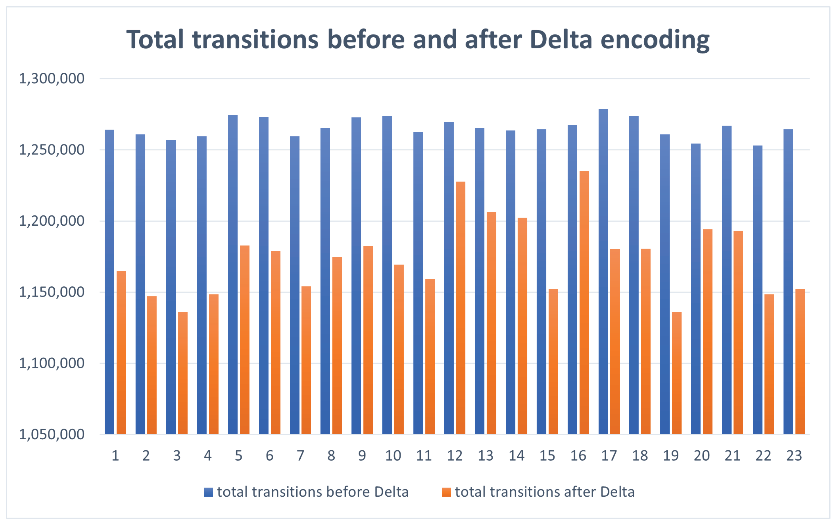
  • A3: Total number of transitions prior to coding ((0-0) + (1-1) + (1-0) + 5 * (0-1)).
  • A4: The total number of transitions following coding ((0-0) + (1-1) + (1-0) + 5 * (0-1)). Comparison results are given in Figure 4.
  • A5: The percentage of reduction of total transitions.
  • A6: The percentage of reduction of transitions 0-1.
As a result of the implementation, the 23 EEG channel consumption presented with an overall reduction of transitions from 0 to 1, ranging from 5.9114% to almost 23.2% between non-coded and encoded signals (Figure 5). The reduction was not significant in some channels (channels 12 and 16), but this can be explained by the fact that power reduction is also dependent on the signal characteristics from specific leads. The use of Delta coding reduced the number of transitions by up to 10% (Figure 6), indicating that the specific solution can extend the power life-cycle of neurostimulation devices.
Summing up the findings of this study, a comparison was performed on three different configurations of a system sampling EEG signals, storing them and transmitting to an external device. The implementations under comparison include only the components that were considered, namely the Input Interface, the Encoder, the Memory, the Compressor and the Transmission Unit. Specifically, a XILINX PYNQ development board was used (integrating a ZYNQ-7000 series device), embedding additionally a BLE component (Arduino compatible) for the transmission. The three system configurations are the following: (1) A system implementing the Input Interface, a Memory and the Transmission Unit. This is the case of raw data storage and transmission. (2) A system implementing the Input Interface, a Memory, a Compressor, and the Transmission Unit. This is the most common case of raw data storage and compressed data transmission. The compressor that was selected was the Compressed Sensing (CS), which is widely used for energy consumption and data compression. (3) The proposed system implementing the Input Interface, a Delta Encoder, a Memory and the Transmission Unit.
Observing the results given in Table 2, we notice that the compression of data benefits the system since it reduces data to be transmitted; however, overall power consumption is significantly increased due to the complexity of the algorithm and the time required to finalise data compression. For this reason, the implanted systems do not transmit data frequently. In contrast, the proposed work depicts that Delta encoding is not increasing power consumption and encoding is performed in real-time. Furthermore, it presents lower power consumption by the other configurations making it suitable for implanted devices requiring extended battery autonomy. Notice that the power dissipation of the BLE module is not given by any tool. It was derived by exhaustive measuring of the overall power dissipation of the system powered by a limited energy source and measuring the data received to the external device. The data that were used for evaluation is the case 21 depicted in the figures. Any comparison to other systems may not be possible, since they do not offer details of power consumption for each component but rather the overall power consumption. Since this is industrial material, there is no access to this information and our study was focused only in the case of light data encoding for power savings during wireless transmission of data.

4. Discussion

The use of neurostimulation for the treatment of epilepsy has markedly increased in the past decade, especially in the USA where the closed-loop RNS system and the most recent open-loop DBS Percept Medtronic device have both been approved by the American Food and Drug Administration (FDA) for use in epilepsy patients and have been evaluated to be refractory to both anti-epileptic medication and traditional resective surgery [8,9,10,12,13]. The fact that the use of these devices in clinical trials has been reliably shown to improve seizure control and the quality of life of epilepsy patients [29,30,31,32], has drawn interest in advancing their technology and extending their potential [33]. Nevertheless, these devices are facing an important issue of short battery life-cycle, assessed to last between 3 and 5 years for DBS [34] and about 3.5 years for the RNS system [32]. As the battery change in all implanted neurostimulation devices requires the patient to undergo a brief but non-trivial surgical procedure under general anesthesia, the power consumption of these devices becomes a key factor that affects both the healthcare costs and the patient’s well being.
Our study investigated and implemented low power strategies targeted for neurostimulation systems in the field of epilepsy that incorporate EEG recording and transmission in either open (DBS Percept Medtronic) or closed-loop (RNS) schemes. The wireless data encoding and transmission system was implemented by means of MATLAB modelling, VHDL coding for integrated systems, and BLE simulation using an Arduino-based system. Furthermore, three systems configurations were examined in a development board embedding a Xilinx ZYNQ-7000 device to measure the power consumption of the proposed system. We used EEG datasets from epilepsy patients, and fed the data through our system. Our implementation resulted in an overall reduction of 0-to-1 transitions up to 23%, with the system’s autonomy increasing as a result of Delta encoding. Our results show that the strategies we employed are directly affecting the energy consumption during BLE transmission; the core concept of this work is focusing on this. However, it should be noted that power dissipation is not reduced exclusively by this process but additionally from the data encoding procedures in the system. The Delta encoding is requiring the least processing power, as supported by the literature described in the Methods section, and only its effect on data transmission is considered in this work for extending the system’s autonomy.
The development and implementation of low power techniques to minimise power consumption in neurostimulation systems for the treatment of epilepsy is an important step towards the design of more sustainable neurostimulators. Energy efficiency implanted devices such as these will save the healthcare system from repeated and costly battery replacement procedures, as well as the patients from being subjected to regular invasive operations under general anesthesia. Our first approach presented here towards this goal has been successful and we envision the application of low power strategies so as to include all functions of a typical neurostimulation device.

Author Contributions

Conceptualization, A.K. and V.K.; methodology, A.K.; software, A.F.; validation, A.F. and A.K.; formal analysis, A.F.; investigation, A.F.; resources, V.K.; data curation, A.F.; writing—original draft preparation, AF.; writing—review and editing, A.K. and V.K.; visualization, A.F.; supervision, A.K. and V.K. All authors have read and agreed to the published version of the manuscript.

Funding

This research received no external funding.

Institutional Review Board Statement

Not applicable.

Informed Consent Statement

Not applicable.

Data Availability Statement

The EEG data used for this study are publicly available at https://physionet.org/content/chbmit/1.0.0/.

Conflicts of Interest

The authors declare no conflict of interest.

Abbreviations

The following abbreviations are used in this manuscript:
RNSResponsive Neurostimulation
EEGElectroencephalography
FDAFood and Drug Administration
DBSDeep Brain Stimulation
LZ77Lempel Ziv 77
LZ78Lempel Ziv 78
CSCompressive Sensing
MCEEGMultichannel EEG
RLERun Length Encoding
FIFOFirst-in-First-out
BLEBluetooth Low Energy

References

  1. Dalkilic, E.B. Neurostimulation devices used in treatment of epilepsy. Curr. Treat. Options Neurol. 2017, 19, 7. [Google Scholar] [CrossRef] [PubMed]
  2. Sisterson, N.D.; Wozny, T.A.; Kokkinos, V.; Constantino, A.; Richardson, R.M. Closed-loop brain stimulation for drug-resistant epilepsy: Towards an evidence-based approach to personalized medicine. Neurotherapeutics 2019, 16, 119–127. [Google Scholar] [CrossRef] [PubMed] [Green Version]
  3. Sander, J.W.; Sillanpaa, M. The natural history and prognosis of epilepsy. In Epilepsy: A Comprehensive Textbook; Engel, P., Pedley, T., Eds.; Raven Press: New York, NY, USA, 1998; pp. 69–86. [Google Scholar]
  4. Velasco, F.; Saucedo-Alvarado, P.E.; Vazquez-Barron, D.; Trejo, D.; Velasco, A.L. Deep brain stimulation for refractory temporal lobe epilepsy. Current status and future trends. Front. Neurol. 2022, 13, 796846. [Google Scholar] [CrossRef] [PubMed]
  5. Velasco, M.; Velasco, F.; Velasco, A.L.; Boleaga, B.; Jimenez, F.; Brito, F.; Marquez, I. Subacute electrical stimulation of the hippocampus blocks intractable temporal lobe seizures paroxysmal activities. Epilepsia 2000, 41, 158–163. [Google Scholar] [CrossRef]
  6. Boon, P.; Vonck, K.; De Herdt, V.; Van Dycke, A.; Goethals, M.; Goossens, L.; Van Zandijcke, M.; De Smedt, T.; Dewaele, I.; Achten, R.; et al. Deep Brain Stimulation in patients with refractory temporal lobe epilepsy. Epilepsia 2007, 48, 1551–1560. [Google Scholar] [CrossRef] [PubMed] [Green Version]
  7. Valentín, A.; García Navarrete, E.; Chelvarajah, R.; Torres, C.; Navas, M.; Vico, L.; Torres, N.; Pastor, J.; Selway, R.; Sola, R.G.; et al. Deep brain stimulation of the centromedian thalamic nucleus for the treatment of generalized and frontal epilepsies. Epilepsia 2013, 54, 1823–1833. [Google Scholar] [CrossRef]
  8. Gregg, N.M.; Marks, V.S.; Sladky, V.; Lundstrom, B.N.; Klassen, B.; Messina, S.A.; Brinkmann, B.H.; Miller, K.J.; Van Gompel, J.J.; Kremen, V.; et al. Anterior nucleus of the thalamus seizure detection in ambulatory humans. Epilepsia 2021, 62, e158–e164. [Google Scholar] [CrossRef]
  9. Sun, F.T.; Morrell, M.J.; Wharen, R.E. Responsive Cortical Stimulation for the Treatment of Epilepsy. Neurotherapeutics 2008, 5, 68–74. [Google Scholar] [CrossRef] [Green Version]
  10. Kossoff, E.H.; Ritzl, E.K.; Politsky, J.M.; Murro, A.M.; Smith, J.R.; Duckrow, R.B.; Spencer, D.D.; Bergey, G.K. Effect of an external responsive neurostimulator on seizures and electrographic discharges during subdural electrode monitoring. Epilepsia 2004, 45, 1560–1567. [Google Scholar] [CrossRef]
  11. Sisterson, N.D.; Kokkinos, V. Neuromodulation of Epilepsy Networks. Neurosurg. Clin. N. Am. 2020, 31, 459–470. [Google Scholar] [CrossRef]
  12. Zawar, I.; Krishnan, B.; Mackow, M.; Alexopoulos, A.; Nair, D.; Punia, V. The Efficacy, Safety, and Outcomes of Brain-responsive Neurostimulation (RNS System) therapy in older adults. Epilepsia Open 2021, 6, 781–787. [Google Scholar] [CrossRef] [PubMed]
  13. Skarpaas, T.L.; Morrell, M.J. Intracranial Stimulation Therapy for Epilepsy. Neurotherapeutics 2009, 6, 238–243. [Google Scholar] [CrossRef] [PubMed] [Green Version]
  14. NeuroPace® Patient Data Management System User Manual Model 4340; NeuroPace: Mountain View, CA, USA, 2014; pp. 1–34.
  15. Youngerman, B.E.; Mahajan, U.V.; Dyster, T.G.; Srinivasan, S.; Halpern, C.H.; McKhann, G.M.; Sheth, S.A. Cost-effectiveness analysis of responsive neurostimulation for drug-resistant focal onset epilepsy. Epilepsia 2021, 62, 2804–2813. [Google Scholar] [CrossRef]
  16. Fragkou, A.A.; Kakarountas, A.P.; Kokkinos, V. Low-power electroencephalographic data encoding system for implantable brain stimulation systems. In Proceedings of the 2021 6th South-East Europe Design Automation, Computer Engineering, Computer Networks and Social Media Conference (SEEDA-CECNSM), Preveza, Greece, 24–26 September 2021; pp. 1–5. [Google Scholar]
  17. Moody, G.B.; Mark, R.G.; Goldberger, A.L. PhysioNet: Physiologic signals, time series and related open source software for basic, clinical, and applied research. In Proceedings of the 2011 Annual International Conference of the IEEE Engineering in Medicine and Biology Society, Boston, MA, USA, 30 August–3 September 2011; pp. 8327–8330. [Google Scholar]
  18. Shannon, C.E.; Weaver, W. The Mathematical Theory of Information; University of Illinois Press: Champaign, IL, USA, 1949; Volume 97. [Google Scholar]
  19. Fano, R.M. The Transmission of Information; Massachusetts Institute of Technology, Research Laboratory of Electronics: Cambridge, MA, USA, 1949. [Google Scholar]
  20. Huffman, D.A. A method for the construction of minimum-redundancy codes. Proc. IRE 1952, 40, 1098–1101. [Google Scholar] [CrossRef]
  21. Rigler, S.; Bishop, W.; Kennings, A. FPGA-based lossless data compression using Huffman and LZ77 algorithms. In Proceedings of the 2007 Canadian Conference on Electrical and Computer Engineering, Vancouver, BC, Canada, 22–26 April 2007; pp. 1235–1238. [Google Scholar]
  22. Freschi, V.; Bogliolo, A. A faster algorithm for the computation of string convolutions using LZ78 parsing. Inf. Process. Lett. 2010, 110, 609–613. [Google Scholar] [CrossRef]
  23. Yan-li, Z.; Xiao-ping, F.; Shao-qiang, L.; Zhe-yuan, X. Improved LZW algorithm of lossless data compression for WSN. In Proceedings of the 2010 3rd International Conference on Computer Science and Information Technology, Chengdu, China, 9–11 July 2010; pp. 523–527. [Google Scholar]
  24. Zhang, Z.; Jung, T.P.; Makeig, S.; Rao, B.D. Compressed sensing of EEG for wireless telemonitoring with low energy consumption and inexpensive hardware. IEEE Trans. Biomed. Eng. 2012, 60, 221–224. [Google Scholar] [CrossRef] [Green Version]
  25. Gurve, D.; Delisle-Rodriguez, D.; Bastos-Filho, T.; Krishnan, S. Trends in compressive sensing for EEG signal processing applications. Sensors 2020, 20, 3703. [Google Scholar] [CrossRef]
  26. Sharma, S.; Chopra, A. The Study: LZW Compression on SEP Protocol.
  27. Kim, S.; Kim, J.; Chun, H.W. Wave2vec: Vectorizing electroencephalography bio-signal for prediction of brain disease. Int. J. Environ. Res. Public Health 2018, 15, 1750. [Google Scholar] [CrossRef] [PubMed] [Green Version]
  28. Nelson, B.D.; Karipott, S.S.; Wang, Y.; Ong, K.G. Wireless technologies for implantable devices. Sensors 2020, 20, 4604. [Google Scholar] [CrossRef]
  29. Fisher, R.; Salanova, V.; Witt, T.; Worth, R.; Henry, T.; Gross, R.; Oommen, K.; Osorio, I.; Nazzaro, J.; Labar, D.; et al. Electrical stimulation of the anterior nucleus of thalamus for treatment of refractory epilepsy. Epilepsia 2010, 51, 899–908. [Google Scholar] [CrossRef]
  30. Jobst, B.C.; Kapur, R.; Barkley, G.L.; Bazil, C.W.; Berg, M.J.; Bergey, G.K.; Boggs, J.G.; Cash, S.S.; Cole, A.J.; Duchowny, M.S. Brain-responsive neurostimulation in patients with medically intractable seizures arising from eloquent and other neocortical areas. Epilepsia 2017, 58, 1005–1014. [Google Scholar] [CrossRef] [PubMed]
  31. Geller, E.B.; Skarpaas, T.L.; Gross, R.E.; Goodman, R.R.; Barkley, G.L.; Bazil, C.W.; Berg, M.J.; Bergey, G.K.; Cash, S.S.; Cole, A.J.; et al. Brain-responsive neurostimulation in patients with medically intractable mesial temporal lobe epilepsy. Epilepsia 2017, 58, 994–1004. [Google Scholar] [CrossRef] [PubMed]
  32. Nair, D.R.; Laxer, K.D.; Weber, P.B.; Murro, A.M.; Park, Y.D.; Barkley, G.L.; Smith, B.J.; Gwinn, R.P.; Doherty, M.J.; Noe, K.H. Nine-year prospective efficacy and safety of brain-responsive neurostimulation for focal epilepsy. Neurology 2020, 95, e1244–e1256. [Google Scholar] [CrossRef] [PubMed]
  33. Stacey, W.C.; Litt, B. Technology insight: Neuroengineering and epilepsy-designing devices for seizure control. Nat. Clin. Pract. Neurol. 2008, 4, 190–201. [Google Scholar] [CrossRef]
  34. Wong, S.; Mani, R.; Danish, S. Comparison and Selection of Current Implantable Anti-Epileptic Devices. Neurotherapeutics 2019, 16, 369–380. [Google Scholar] [CrossRef]
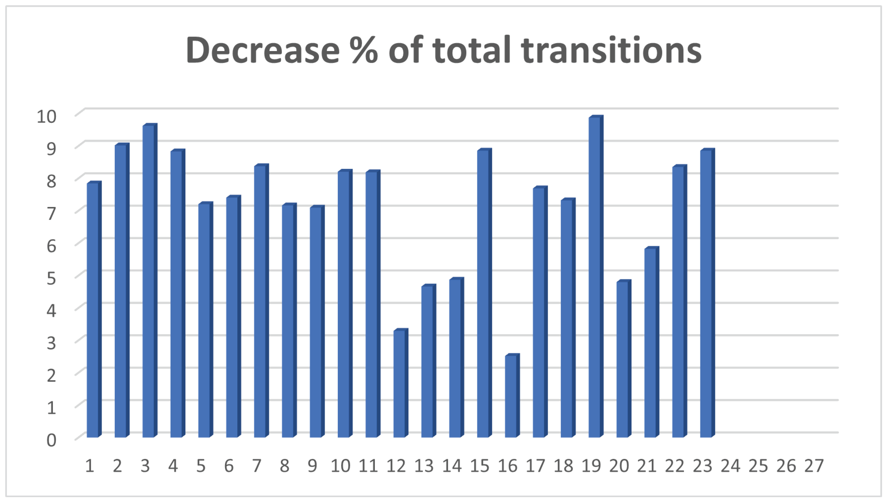
Figure 1. The system modules and interconnection design.
Information 13 00194 g001
Figure 2. Evaluation of accurate EEG data transmission with Arduino. The values received by Arduino from the computer are identical to the values transmitted to the smartphone.
Information 13 00194 g002
Figure 3. Bar chart of 0-1 transitions before and after Delta encoding for all the leads examined.
Information 13 00194 g003
Figure 4. Bar chart of 0-0, 0-1, 1-0, and 1-1 transitions before and after Delta encoding for all the leads examined.
Information 13 00194 g004
Figure 5. Bar chart of % reduction of 0-1 transitions after the encoding.
Information 13 00194 g005
Figure 6. Bar chart of % reduction of 0-0, 0-1, 1-0, and 1-1 transitions after the encoding.
Information 13 00194 g006
Table 1. Comparison of the transitions before and after Delta encoding.
A0A1A2A3A4A5A6
1673,220549,5151,264,0961,164,9807.840918.3751
2669,515527,2701,260,8451,147,1829.014821.246
3664,420513,6001,257,0391,136,1209.619422.6995
4667,430528,9451,259,5971,148,3928.828620.749
5686,040571,7751,274,4601,182,6787.201616.6557
6684,600567,0051,273,2481,178,9867.403317.1772
7667,360535,9501,259,5461,154,0848.37319.691
8674,605561,4701,265,4011,174,7667.162616.7706
9684,020571,6051,272,8301,182,5447.093316.4345
10685,315554,9001,273,8151,169,3228.203219.0299
11671,190542,4651,262,6201,159,2658.18588.1858
12679,765627,5551,269,5191,227,7363.29127.6806
13674,980601,4351,265,5261,206,5534.6610.8959
14672,665595,7251,263,7141,202,1934.868311.4381
15673,250534,1301,264,3911,152,4708.851820.6639
16676,825636,8151,267,1591,235,2782.51595.9114
17691,235568,5751,278,5941,180,2877.688717.7451
18685,225568,7651,273,7321,180,5227.317916.9959
19668,810513,7601,260,7441,136,2819.872223.183
20661,190586,2851,254,5081,194,3164.798111.3288
21676,470584,7051,266,8651,193,1105.821913.5653
22659,300528,7901,253,0641,148,4678.347319.7952
23673,250534,1301,264,3911,152,4708.851820.6639
Table 2. Comparison of three configurations in Xilinx ZYNQ-7000 device.
I.I.EncoderMemoryCompressorBLETotal
FFLUT
(%)
FFDSP
(%)
BRAM
(%)
Power (W)BRAM
(%)
Power (W)LUT
(%)
FFDSP
(%)
BRAM
(%)
Power (W)Power (W)Power (W)
132-----400.072-----0.180.252
232-----400.07242207300.2210.140.433
3321632000.004400.072-----0.160.236
Publisher’s Note: MDPI stays neutral with regard to jurisdictional claims in published maps and institutional affiliations.

