Abstract
Internet of Things comprises an increasing number of interconnected smart devices, where communication happens anytime, anywhere, reducing hardware costs and the complexity of the architectures. Reading Radio Frequency Identification tags using ultra high frequency is a high-cost activity because of its infrastructure and the radio frequency identification tag reading device for these frequencies. This work proposes an architecture that enables the cost reduction of Radio Frequency Identification tag reading equipment operating ultra high frequency in an infrastructure using cloud computing and microservices. The use of cloud computing and microservices was necessary due to scalability and the management of large volumes of data that can be generated by reading Radio Frequency Identification tags using ultra high frequency and the complexity of the architecture related to the theme of this work. The proposed architecture was applied in a real case study to verify its adherence and compliance. The proposed architecture can be used in any system that presents similar characteristics to the one proposed in this work. In scenarios where reading distance is a fundamental requirement, it is necessary to include an external antenna for better results. Other practical experiments will be carried out to evaluate the use of the proposed architecture in other contexts related to the use of Internet of Things and reading of Radio Frequency Identification tags.
1. Introduction
The Internet of Things (IoT) is a paradigm for building computer systems distributed over the Internet, in which, in principle, the most diverse devices, objects and things will be connected and interacting with applications to extend various services to people [1,2]. IoT involves a growing number of interconnected smart devices and sensors that are generally not intrusive, transparent, and invisible. Communication between these devices should happen anytime, anywhere, making communication decentralized and complex [3].
Ashton [4] proposed IoT to address its use in the logistics area using Radio Frequency Identification (RFID) for the tracking of items. RFID uses radio waves to perform item identification. Items are identified on an RFID tag, which can be tracked in real time. RFID radio waves operate in three frequency regions: Low Frequency (LF), High Frequency (HF), and Ultra high frequency (UHF) [5,6]. Cloud computing is a distributed, parallel system that consists of a collection of interconnected and virtualized computers that are provisioned dynamically. Applications in cloud computing are exposed as sophisticated services that can be accessed over a network [7].
Microservices are architectural pattern inspired by Service Oriented Architecture (SOA). These are small, independent services that communicate with each other to form applications that use the Application Programming Interface (API) [8,9]. Microservices were introduced in the field of IoT application because of their flexibility, low coupling and scalability, unlike monolithic applications, which become much larger in scale with even more complex structure. The use of cloud computing in the microservice architecture is very common, due to its high availability and extensibility that allows provisioning microservices quickly [10].
Reading UHF RFID tags is a high-cost activity that can involve a large volume of data on a large scale, requiring considerable investment, and thus raising the cost of a project [11,12,13]. To reduce the cost of infrastructure and UHF RFID tag reading equipment, an architecture using IoT should be created. The use of cloud computing and microservices is necessary due to scalability and the management of large volumes of data that can be generated by reading Radio Frequency Identification tags using ultra high frequency and the complexity of the architecture related to the theme of this work.
This article proposes an Internet of Things architecture for reading UHF RFID tags, using cloud computing and microservices. To validate the methodology, a case study is presented applying the architecture proposed in this paper.
This paper is organized as follows: Section 2 presents the background, relating our work with the existing literature. Section 3 shows the related work. Section 4 explains the architecture proposed in this work. Section 5 presents the results of a case study that validate our approach. Finally, Section 6 displays the final considerations of this article and future work.
2. Background
2.1. Internet of Things
Internet of Things allows all kinds of “things” that are real-world objects to be connected to the Internet and interact with each other with minimal human intervention [14,15]. An IoT involves connected smart files and sensors that are not usually intrusive [3]. The difference between the Internet and the sensor networks is the intelligence that the Internet has in its domain, transforming information and actions into knowledge. In this way, this knowledge feeds a network, new actions and contact information [1,16]. IoT enables people and objects to be connected anytime, anywhere, with any device, with any service and using any communication path. Communication is often done autonomously and performed on a network [15].
The IoT architecture is defined as a framework for specifying the physical components of a network, its organization and functional configuration, its principles and operational procedures, and the data formats used in its operation [17]. The IoT architecture is defined in five layers [14]: Perception Layer, Network Layer, Middleware Layer, Application Layer, and Business Layer. Figure 1 presents and describes the IoT architecture.
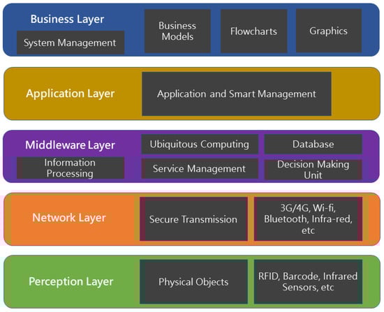
Figure 1.
Layered architecture of IoT [14], Adapted.
- Perception Layer: The Perception Layer is also known as the Device Layer. It consists of physical objects and devices. The devices can be Radio Frequency Identification (RFID), bar code, infrared sensor, depending on the method of identification of objects. This layer basically deals with the identification and collection of object-specific information by the devices. Depending on the type of sensors, the information can be about location, temperature, orientation, movement, vibration, acceleration, humidity, etc. The collected information is then sent to the Network Layer for secure transmission to the information processing system.
- Network Layer: The Network Layer is also known as the Transmission Layer. This layer reliably transfers information from the devices and sensors to the information processing system. The transmission medium may be wired or wireless and the technology may be 3G/4G, Wi-Fi, bluetooth, etc. The Network Layer transfers the Perception Layer information to the Middleware layer.
- Middleware Layer: IoT devices implement different types of services. Each device connects and communicates only with other devices that implement the same type of service. This layer is responsible for managing services and has a link to the database. It receives information from the network layer and stores it in the database. The Middleware Layer performs information processing and ubiquitous computing and makes automatic decisions based on results.
- Application Layer: This layer provides global device management based on the information of objects processed in the Middleware Layer. The applications implemented by IoT can be for smart health, intelligent agriculture, smart home, smart city, intelligent transportation, etc.
- Business Layer: This layer is responsible for managing the overall IoT system, including applications and services. It builds business models and graphs based on data received from the Application Layer. The true success of IoT technology also depends on good business models. Based on the results analysis, this layer will help determine future actions and business strategies.
IoT allows many applications to be created in different application domains. The application domain can be divided mainly into three categories based on its focus: industry, environment and society. Transportation and logistics applications, aerospace, aviation and automotive are some of the applications focused on the industry. Telecommunication, medical technology, health care, smart building, home and office, media, entertainment and ticketing are some of the applications focused on society. Agriculture, recycling, disaster warning, environmental monitoring are some of the applications focused on the environment [14,15].
IoT implementations have several benefits, including improving the efficiency of applications that require interaction with physical devices, increasing the flexibility and interactions of applications and the cost reduction of applications that use IoT.
2.2. RFID
Radio Frequency Identification (RFID) uses radio waves and electromagnetic fields to automatically read or write information stored on RFID tags [5].
Many of us already use RFID tags routinely. Examples include proximity cards, automated toll-payment transponders, and payment tokens. The ignition keys of many millions of automobiles include RFID tags as a theft-deterrent. In a world where everyday objects carried RFID tags, remarkable things aree possible [18].
RFID tags have a unique identifier known as the Electronic Product Code (EPC) that identifies a crawled tag [19,20].
There are three types of RFID tags in relation to their power: passive, semi-passive and active [5,6,18].
Passive RFID tags do not have internal power sources. When receiving the radio frequency signal from the RFID tag reader, some of this energy is transformed into electrical current inside the RFID tag, which sends a response signal with information on the chip of the RFID tag. The passive tag has a lower cost than the other types of tags, but it is necessary that the RFID tag reader must be more powerful because of the amount of energy needed to emit the response signal present in the RFID tag [5].
Semi-passive RFID tags have a power source using an internal battery. The internal battery is activated by receiving a radio frequency signal from the RFID tag reader. The internal battery is used to power the chip present inside the RFID tag, while the energy used for communication is received by the RFID tag reader [5].
Active RFID tags also have a power source using an internal battery. The internal battery is activated by receiving a radio frequency signal from the RFID tag reader. The active RFID tag is able to emit its signal continuously, regardless of the reception of the RFID tag reader. The active tag has a higher cost than the other types of tags, but can be identified at greater distances and has greater capabilities within the chip in the RFID tag [5].
The identification of an RFID tag occurs when it is within a proximity of an RFID reader, the radio signal is transmitted by the reader next to the tag. The tag receives the signal and then identifies itself with the reader by its unique EPC identifier. The reader captures the signal sent by the tag, and transmits the information to a software system responsible for processing the RFID tag information. This transmission can occur in various ways, such as from the Internet, Wi-Fi, serial communication, Bluetooth, etc. [6,21]. RFID systems can be classified by their type of frequency and region of frequency [13]: Low Frequency (LF), High Frequency (HF) and Ultra High Frequency (UHF).
- Low Frequency (LF)—30–500 Kilo-hertz (KHz): Low cost and low read and write range.
- High Frequency (HF)—10–15 Mega-hertz (MHz): Potentially low cost and average read-write range.
- Ultra High Frequency (UHF)—850–950 Mega-hertz (MHz), 2.4–3.5 Giga-hertz (GHz) and 5.8 Giga-hertz (GHz): High cost and high read and write range.
Unlike barcodes, RFID tags do not need to be within the recipient’s field of view to be tracked, resulting in greater efficiency and speed in searching for items with RFID tags.
2.3. Cloud Computing
Cloud computing is a type of parallel and distributed system, consisting of a collection of interconnected and virtualized computers, dynamically provisioned and made available as computing resources (e.g., networks, servers, storage, and applications [7]). Computational resources are made available based on a Service Level Agreement (SLA) established through negotiation between cloud service providers and their customers. Cloud computing environments are quickly configured and released with minimal management effort or interaction with service providers [22].
The term cloud, present in cloud computing, denotes the infrastructure where users can access applications embedded in the environment from anywhere in the world, at any time. Thus, the computing world is rapidly evolving into software development using cloud services, rather than running such software in local environments and infrastructures [22,23]. Cloud computing platforms feature grid computing and clustering with special attributes and features such as virtualization support, dynamically composed services with Web interfaces for management, and ease of configuration of environments. Cloud computing provides services to users without reference to the infrastructure in which they are hosted [7].
The architecture of cloud computing provides service models, each of which deals with a particularity in the availability of resources for the applications: Infrastructure as a Service (IaaS), Software as a Service (SaaS) and Platform as a Service (PaaS) [22,23,24]. In the IaaS model, the service provider provides servers as virtual machines that are consumed as services. The customer of this type of service is responsible for all configuration in this type of model. In the SaaS model, the service provider is responsible for the entire structure necessary to make the system available, such as infrastructure, security and connectivity. The customer of this type of service pays a value for the service that is accessed via the Internet. The PaaS model is a middle ground between IaaS and SaaS, where the service provider offers the two in a single model [7].
In addition to providing service models, the cloud computing architecture provides deployment models: public, private, hybrid, community, and federated [7,25]. The public model is the most common implementation model and has the open network structure for public use. The customer uses the service through a payment according to the services used. The private model has a closed network structure. The customer is responsible for internal control of all services. The hybrid model is a middle ground between the private and public model. Services used by the client can be in either a private cloud or a public cloud. The community model occurs when organizations build and share a cloud infrastructure together. The federated model is a set of public and private cloud providers [22,23,24,25].
Cloud computing providers have data centers scattered around the world to provide redundancy and reliability over established services. Regardless of the service architecture used or implementation model, cloud computing providers must ensure that their infrastructure is secure and that their customers data and applications are protected, while the customer must take steps to strengthen their applications. The cost savings of cloud computing compared to local infrastructure is evident, as well as being an important technology for interoperability, flexibility, scalability and rapid provisioning of applications [22,23,24].
2.4. Microservices
Microservices are architectural styles inspired by Service Oriented Architecture (SOA). These are small, independent services that communicate over a network to form applications that use the Application Programming Interface [8,9]. Microservices have fundamental differences in relation to SOA. Services should be small, with a single responsibility, independent infrastructure and the contexts should be delimited and well-defined. The concept of delimited contexts was imported from the Domain-Driven Design (DDD) architectural pattern where the business functions of a service must be constructed and executed independent of other services [8].
SOA service integration is performed with middleware that facilitates message routing, data transformation, protocol transformation, and business rule application [8,26]. In microservices, service integration happens through design patterns such as: APIgateway for external communication between services, messaging to use asynchronous messages for communication between services, and backend for front-end, among other patterns [27,28].
The use of microservices diverges the monolithic architectural style. In a monolithic application, a software application cannot be run independently. The software is built with the same set of technology and infrastructure. A major problem in this architectural approach is the addition or update of programming languages, framework, database, or infrastructure that affects the entire construction of the application [8,26].
Microservices have a clear separation of all components of a software application, unlike the monolithic one, which centralizes all components. Each microservice has its own infrastructure and defined business definition, and can be shared among other services. A software application is built by decomposing multiple microservices. The development of microservices besides being important for the knowledge of the delimited contexts of an application, facilitates the maintenance and the fast provisioning of applications.
3. Related Works
In the paper presented by Rayes et al. [3], the importance of the Internet of Things Architecture is affirmed to manage the complexity of intelligent devices interconnected with sensors. Cloud computing enables provisioning services quickly, as well as ensuring high availability and extensibility, which are important for managing the complexity of an IoT architecture [10,16].
Martins [26] presented the architecture in IoT using cloud computing and microservices, defining the influence of the Service Oriented Architecture (SOA) to make available the processed data of an IoT device through the architectural approach Representational State Transfer (REST) and architecture of microservices. In the work of Vresk and Cavrak [29], Celesti [30], Vandikas [31] and Sun [10] IoT architecture is presented using cloud computing and microservices. The work demonstrates how the characteristics of cloud computing and microservices complement each other in architectural design using IoT.
Microservice features facilitate communication and integration with IoT devices [8,9,28]. The works of Ferreira et al. present IoT architectures using services in the architectural style Representation of State Transfer and architecture SOA, for its ease of communication with IoT devices [32,33].
Tsiropoulou [34] demonstrated the adoption of passive RFID tag-to-tag communication paradigm, within which the context of a smart parking system is evangelized, in terms of achieving improved energy-efficiency and operational effectiveness. To demonstrate that the joint routing and RFID readers transmission power minimization problem is studied, considering tag-to-tag communication.
The works of Prudanov [11], Farris [12] Chieochan [13] present UHF RFID tags reading architectures using IoT. Prudanov [11] presented an architecture of reading UHF RFID tags using IoT. The proposed architecture uses an IoT reader for reading low-cost RFID tags. A microcomputer Raspberry Pi 3 is responsible for processing the tags read by the IoT device. The proposed architecture implements application security authentication to enforce data confidentiality. Farris [12] presented a read and write architecture of UHF RFID tags using IoT in an environment with communication via IPV6 communication protocol. The proposed architecture uses an IoT reader for reading and writing low cost commercial ThingMagic Micro Embedded RFID tags. Read or write information for tags is sent to a local server using serial communication.
Chieochan [13] demonstrated a UHF RFID tag reading architecture using IoT and cloud computing. The proposed architecture uses a high-cost commercial RFID tag reader and a microcontroller to perform the processing of the read tags that are sent to a local server. The connection between the microcontroller and the RFID tag reader is performed from the serial communication using a Universal Asynchronous Receiver/Transmitter (UART) hardware. The Database Management System (DBMS) MariaDB is responsible for storing information in the JSON format. Cloud computing is used through the private cloud model, which is responsible for storing the information present in the database and hosting the Web application responsible for demonstrating the results.
The use of low cost hardware in IoT is fundamental for reducing the cost of implementing complex IoT architectures. There are several IoT devices that have an affordable market price for small businesses and/or common users.
The presented IoT architectures with UHF RFID tag reading have common characteristics, mainly in terms of communication and integration between the IoT devices and the applications. Most of the IoT architectures make use of the communication between services using the REST architecture with JSON format to return the message from the services, as well as a DBMS with support to this technology. This type of communication is light and essential for the provision of IoT device information.
Contrasting the IoT architectures with UHF RFID tag reading presented, the architecture proposed in this article makes use of microservices because of their characteristics already presented. These features are essential for the management of large IoT architectures, as well as the management of large volumes of data that can be generated in reading RFID tags. Using a Not Only SQL (NoSQL) database is important for the amount of information that can be generated.
The use of cloud computing in the proposed architecture is another feature different from that presented. Cloud computing facilitates the provisioning of microservice applications, and provides all the advantages of using microservices. The use of the public implementation model and the PaaS service model reduces the cost of implementation and facilitates the development of the microservices.
Choosing Docker [35] container technology facilitates the integration between microservices with different programming languages, and it is possible to use other types of cloud computing providers that accept this type of technology.
Finally, the architectures presented above do not have implementations for monitoring IoT hardware. The architecture proposed in this paper presents the monitoring of the IoT device as well as the monitoring of the implemented microservices.
4. Proposed Architecture
The abstract architecture proposed in this paper is aimed at the management of the IoT device for reading RFID tags, as well as the availability of data using services provided by microservices and cloud computing. The proposed architecture is implemented according to the standard architecture for Internet of Things, as described in Section 2.1. Figure 2 presents the proposed architecture using the type of layered architecture, consisting of five layers: Perception Layer, Network Layer, Middleware Layer, Application Layer and Business Layer.
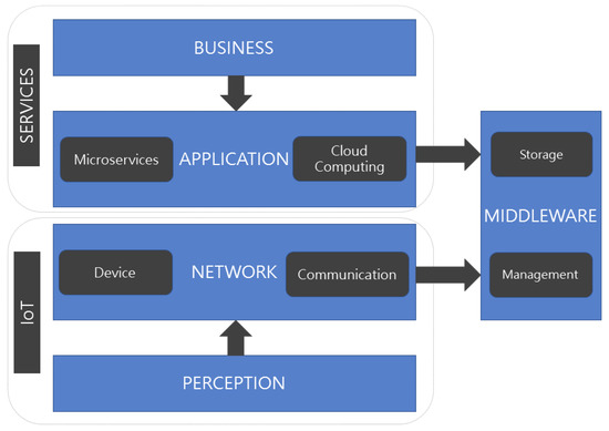
Figure 2.
Abstract architecture of the proposed solution.
- Perception Layer is responsible for identifying and collecting information from the IoT device for reading RFID tags.
- Network Layer is responsible for transmitting the data generated by IoT device and its communication with a local server.
- Middleware Layer is responsible for processing, managing and storing the data generated by the IoT device.
- Application Layer is responsible for providing the data generated by the IoT device.
- Business Layer is responsible for presenting the data generated by the IoT device for user interaction.
The Perception Layer consists of identifying and collecting information from the IoT device reading RFID tags. The IoT device has two types of events in its communication: read event and log event. The read event occurs when reading a tag is performed, while the log event occurs when there is an error in reading a tag. A third event is responsible for monitoring the telemetry of the IoT device. The monitoring event is responsible for sending information about the status of the IoT device. For each event performed by the IoT device, the generated data are processed in the Network Layer.
The Network Layer consists of transmitting the data generated by the IoT device, as well as communicating with a local server. The data generated in the read and log events performed on the IoT device, in addition to the telemetry monitoring event, are sent to the Middleware Layer.
The Middleware Layer consists of the processing, management, and storage of data generated by the IoT device. The data received from the network layer are processed and stored in a Not Only SQL (NoSQL) database because of the large volume of information that can be generated, as well as the need for high availability and scalability of the architecture.
Application Layer consists of providing services using the microservice standard with the use of cloud computing. The use of microservices and cloud computing have characteristics that are essential for managing large IoT architectures. This layer exposes the information stored in the Middleware Layer so that it can be used in the Business Layer.
The Business Layer consists of viewing the information provided by the Application Layer services that expose the information of the IoT device.
The proposed architecture, in addition to being represented by five layers, is divided into two main groups: Internet of Things Group and Services Group.
- Internet of Things Group is composed of the Perception Layer and Network Layer.
- Services Group is composed of the Application Layer and Business Layer.
The Middleware Layer is shared between the two architecture groups. Layer and group architectural separation is necessary for better hardware utilization, decentralization of data management and storage, and especially for the processing of data generated by the IoT device.
The following sections provide a detailed view of the operation of the architecture. The groups present in the architecture are detailed within the architecture layers.
4.1. Internet of Things Group
The Internet of Things Group is composed of the Perception Layer and Network Layer, and is responsible for sending the information generated by the IoT device to the Middleware Layer. Figure 3 shows the architecture of the Internet of Things Group responsible for reading and communication of the IoT device, its processing in relation to the read and log events, besides the event of monitoring the telemetry and storing the data in a NoSQL database using a cloud computing environment.
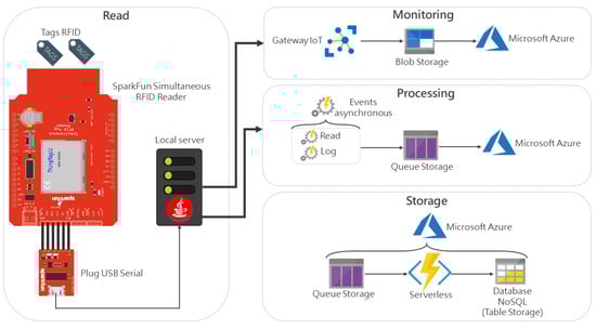
Figure 3.
Architecture of Internet of Things Group.
To perform the reading of RFID tags, the proposed architecture uses the board SparkFun Simultaneous RFID Reader—M6E Nano as the IoT device for reading RFID tags. This device is low cost and performs RFID tag reading using ultra high frequency (UHF). The SparkFun Simultaneous RFID Reader—M6E Nano board performs the Perception Layer function by reading RFID tags from its internal antenna located on the top of the board, as shown in Figure 3. In this paper, the passive tag and the UHF frequency are used, respectively, due to the lower cost than the other types of tags and to the high reading distance of the RFID tags.
Board communication is performed using an adapter for serial communication using Universal Asynchronous Receiver/Transmitter (UART) hardware. Serial communication, one of the communications type available on the board, performs the function of the Network Layer. This technique was chosen so that it was not necessary to involve other hardware such as a microcontroller or computer for communication with the board. With serial communication, it is possible to connect with any of these hardware transparently. The communication is performed on a locally hosted server, so it is possible to connect using a Universal Serial Bus (USB) port on the local server. This connection could be performed on a microcontroller or microcomputer in the same way or using another type of communication present in the Network Layer.
The local server performs the function of the Middleware Layer, being responsible for the processing, management and storage of the data generated by the board. The local server used has the following settings:
- Operational System:Windows 10;
- RAM: 16 Gigabytes;
- CPU: Intel Core(TM) i7 6500U/2.50 GHz;
- GPU: 4 Gigabytes; and
- Flash Drive: SSD Samsung 500 Gigabytes/520 Megabytes (read and write).
The local server software was developed in the Java programming language, due to the interoperability of the language in any Operating System (OS). In this context, the local server used could have any OS. This software is responsible for processing information from the read and log events that occur on the board, as well as performing telemetry monitoring.
The read and log events performed by the board, besides monitoring the telemetry, are processed asynchronously, so they can occur simultaneously, without any bottleneck in the processing of the requests of the events.
The use of the Microsoft Azure [36] cloud computing provider is due to its representatives in the cloud computing market, as well as having services and tools that facilitate the implementation of the proposed architecture. In the proposed architecture, the public implementation model and the service model Platform as a Service (PaaS) are used due to the low implementation cost and the ease of development of this type of service.
The telemetry monitoring of the board is performed using the Gateway IoT, IoT Hub, and a service offered by Microsoft Azure. The IoT Hub service is compatible with the main programming languages and communication protocols. One of the programming languages offered in the service is the Java language, implemented on the local server for the processing of architecture events.
The telemetry monitoring processing of the board is performed on the local server and the data is sent in JavaScript Object Notation (JSON) format to the IoT Hub service to be stored in a Blob Storage service, which is provided by Microsoft Azure specifically for storage of the Binary Large Object (BLOB) file type. The BLOB file type is a collection of binary data that are stored as a single entity. It is an ideal collection of data to store any type of unstructured data. If there is any change in the format of the JSON telemetry file, no adjustment is required in the storage of this type of file.
The following telemetry information is monitored by the IoT Hub service in this architecture: temperature, location, and intermittent connectivity. Temperature monitoring is important to check the heating of the board in possible peaks of reading RFID tags or to monitor any excessive heating on the board at any time. The location is important so that the board can be monitored and managed remotely. Checking for intermittent connectivity of the board is the most important function in this type of service, being possible to know whether the board has some unexpected behavior and if it is in constant operation.
Besides monitoring the telemetry generated by the board, the use of this type of service is important for the high availability and scalability of the architecture, where other devices can be connected to the architecture and be monitored and managed. For this reason, the use of an IoT Gateway is necessary.
When some read or log event occurs on the board, the data are processed and sent by the local server in JSON file format to be stored in a Queue Storage service provided by Microsoft Azure. The use of queue for storage of the read or log events of the board is important for resiliency in sending the data, making the architecture scalable and less sensitive to individual failures of other architecture components. This type of storage prevents the database from receiving a large number of concurrent requests because of the large amount of data that can be generated, thus preventing unavailability of storage and data access.
The storage of the data generated by the board occurs when there is some information stored in the queue. A Microsoft Azure service that uses the Serverless architecture, Azure Functions is responsible for“listening” to the data stored in the queue and sending that data to a NoSQL database. Azure Functions are implemented in the C# programming language. Azure Functions are hosted on Microsoft Azure in the background, being triggered only when there is some information stored in the queue.
The use of the Serverless architecture is required by the background context of this type of service. The NoSQL Table Storage database used for storage is a Microsoft Azure service. Table Storage is a NoSQL database that uses the key-value concept. This type of NoSQL database was chosen because it is ideal for storing semi-structured data, scalable applications, and flexible data schema.
The stored data of the read and log events performed by the board located in the Table Storage and the board telemetry monitoring data stored in the Blob Storage are accessed by the Services Group using microservices and cloud computing.
4.2. Services Group
The Services Group contains the Application Layer and Business Layer, in addition to being responsible for communicating with the information stored in the Middleware Layer. The Application Layer consists of providing services delivered by microservices and cloud computing. These services are consumed in the Business Layer to expose the information. Figure 4 presents the Services Group architecture using microservices in a cloud computing environment.
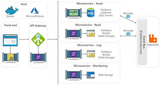
Figure 4.
Architecture of Services Group.
The Services Group is composed of four microservices:Asset microservice, Read microservice, Log microservice and Monitoring microservice. Each Application Programming Interface (API) of the microservice is implemented using the architectural style Representation of State Transfer (REST) with the return of the response from the microservices in JSON format.
The Asset microservice is implemented using the NodeJS [37] web framework in the JavaScript programming language. This microservice is responsible for providing the information of physical objects that are identified with an RFID tag. The asset microservice data are stored in the SQL Server database, hosted on Microsoft Azure. A relational database is used, since it is a common database type for storing information. Data storage could use any other type of database. This decision is the responsibility of who is consuming the proposed architecture.
The Read microservice is responsible for making available the RFID tag readings. The Log microservice is responsible for providing error information that may occur when reading RFID tags. The microservices are implemented using the Web framework ASP.NET Core [38], in the C# programming language. As presented in the Internet of Things Group architecture in Section 4.1, the data from these micro-services are stored in the NoSQL Table Storage database and hosted on Microsoft Azure.
The Monitoring microservice is also implemented using the Web framework ASP.NET Core, in the C# programming language. This microservice is responsible for providing the telemetry information of the SparkFun Simultaneous RFID Reader—M6E Nano board. As shown in the Internet of Things Group architecture, the data from this microservice is stored in a Blob Storage in the BLOB file format.
Communication between the microservices is performed through message events using the Publish-subscribe project pattern [8,28]. The Asset microservice communicates via a message event with the Read microservice which notifies it via message event if there is any RFID tag reading associated with any physical object linked to the Asset microservice database. The management of the service bus and the sending of these message events is controlled by RabbitMQ [39], an open source tool, implemented in the Asset and Read microservices. The Log and Monitoring microservices do not have the need to communicate with other microservices, as they do not have dependence on information.
The communication of the microservices with the front-end application is performed using a API Gateway. The API Gateway is responsible for managing and monitoring the microservices. In the proposed architecture, all microservices are exposed to be consumed in the front-end application. The API Gateway is implemented using the Web framework ASP.NET Core, in the C# programming language. The use of a API Gateway in the microservice architecture is important for the availability and scalability of the architecture, where other microservices can be connected to the architecture to be monitored and managed. For this reason, the use of a API Gateway is necessary.
The front-end application performs the role of the business layer, exposing the microservices implemented in the Application Layer. It uses the API Gateway to consume the deployed microservices. The front-end application has been implemented using the Angular [40] Web framework in JavaScript programming language.
Microservices, API Gateway, and the front-end application are provisioned in containers using Docker technology, hosted on Microsoft Azure, using Linux OS. The use of Docker container technology facilitates provisioning of microservices and integration between microservices with different programming languages [31,41]. Besides that, it facilitates a possible change of the application to another cloud provider. In addition, it can deploy microservices, the API Gateway and front-end application in any other programming language that provides support for building APIs.
5. Case Study
According to Runeson [42], the case study is an empirical study to investigate the occurrence of a phenomenon of contemporary software engineering within its real life context, especially when the boundary between the phenomenon and the context cannot be clearly specified. The case study technique was used in this work because it is a technique widely used in qualitative research and able to gather detailed information about a given problem.
The case study was applied to a medium-sized company that cannot be named due to copyright agreement. The Company operates in the asset management area. The equity asset management is performed using mobile readers of RFID tags and RFID antennas exposed in some strategic points of the client companies. These strategic points can be garages, concierge, confidential rooms, etc. The architecture proposed in this work aims to contemplate the patrimonial management using RFID antennas. The Company has clients in banking, engineering and hospitals, with approximately 100,000 assets registered in its database.
The practical case study aimed to answer the following research questions:
- RQ.1. In the proposed architecture, is it possible to verify if a physical object identified with an RFID tag by the SparkFun Simultaneous RFID Reader—M6E Nano board is registered in the database of the Asset microservice?
- RQ.2. In the proposed architecture, is it possible to monitor the SparkFun Simultaneous RFID Reader—M6E Nano board’s telemetry?
- RQ.3. In the proposed architecture, is it possible to monitor the implemented microservices?
Question RQ.1 is related to a very important concern in the context of this work, that is, with the identification of a physical object identified with an RFID tag by Arduino board linked to a physical object previously registered in the database that is consumed by Asset microservice. It was intended to demonstrate how the proposed architecture presents the identification of a physical object.
Question RQ.2 is related to the visualization of the telemetry monitoring of the SparkFun Simultaneous RFID Reader—M6E Nano board. It aws intended to demonstrate how the Microsoft Azure cloud computing provider through its Gateway IoT service, IoT Hub, provides the following board telemetry information: temperature, location, and intermittent connectivity.
Question RQ.3 is related to the visualization of the monitoring of the microservices implemented in the proposed architecture. It was intended to demonstrate how the API Gateway and the Microsoft Azure cloud computing supplier provide the information about monitoring the deployed microservices.
5.1. Data Collection and Analysis Procedures
To perform the data collection and analysis of the results, all the proposed architecture was implemented to answer the research questions destined to the case study of this work. After the identification of an RFID tag reading by the SparkFun Simultaneous RFID Reader—M6E Nano board, processing and storage of the reading information, the Asset microservice needs to communicate with the Read microservice to check if there is any related physical object between them. This check happens through the EPC of the RFID tag field present in the relational database of the Asset microservice and in the NoSQL database of the Read microservice. As the EPC of an RFID tag is a unique identifier, this is the only field necessary to verify whether an RFID tag identified by the SparkFun Simultaneous RFID Reader—M6E Nano board and registered in the database of the Read microservice is in the Asset microservice database. Responding thus to Question RQ.1. of the case study.
Table 1 summarizes a query performed in the Asset microservice database. The physical objects present in the query of the database of the Asset microservice were previously registered and linked to the EPC of RFID tags.

Table 1.
Result of a query in the Asset microservice database.
Figure 5 shows the return of the response from the Read micro-service in the JSON format. The return of the API response presents the EPC field, unique identifier between the Asset and Read microservices; the Antenna field, identifier of the number of the antenna where the RFID tag was read; and the Read Date field, responsible for identifying when the reading of the RFID tag occurred.
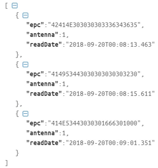
Figure 5.
JSON file of the Read microservice response.
Figure 6 shows the screen in the front-end application of the physical objects identified with the RFID tag read by the SparkFun Simultaneous RFID Reader—M6E Nano board that is registered in the database of the Asset microservice.
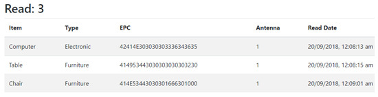
Figure 6.
Front-end application presenting the physical objects identified.
After collecting telemetry information from the SparkFun Simultaneous RFID Reader—M6E Nano board’s temperature, location, and intermittent connectivity information using the Microsoft Azure, IoT Hub service, the Monitoring microservice is used to display the collected data. This answers Question RQ.2 of the case study of this work.
Figure 7 shows the screen image in the front-end application of telemetry monitoring of the SparkFun Simultaneous RFID Reader—M6E Nano board. The temperature field is represented by the unit of measurement of the board, dBm (decibel milliwatt); the location field shows where the board is located; the connectivity field shows if the board is in operation; and the data field displays the information from the performed monitoring.
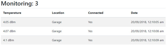
Figure 7.
Front-end application featuring SparkFun Simultaneous RFID Reader—M6E Nano board monitoring.
To answer Question RQ.3 of the case study, a Microsoft Azure service was used to perform the monitoring of applications hosted by the provider. The Application Insights service performs the monitoring of the microservices, being able to diagnose exceptions and performance problems, and presents metrics of use of the microservices. In the proposed architecture, the API Gateway is the monitored application because it is responsible for managing and monitoring the microservices to be exposed in the front-end application.
Figure 8 shows the monitoring performed on the microservices used by the API Gateway. It is possible to observe that any inconsistency in services is displayed in monitoring through the red line. The green line shows that services are stable.
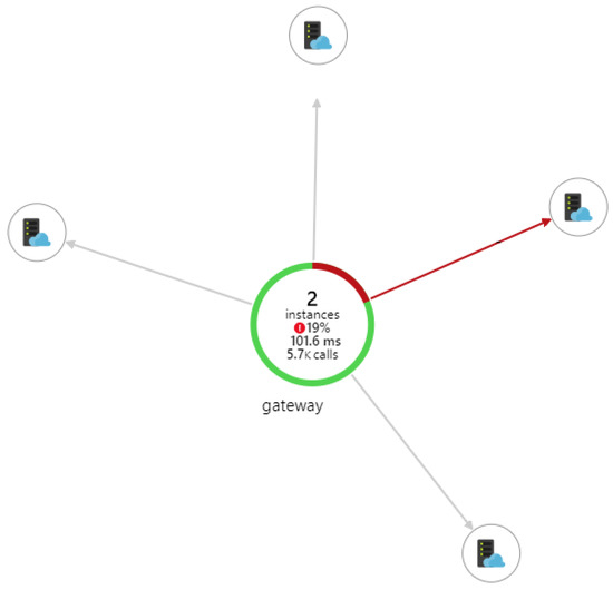
Figure 8.
Monitoring of the microservices used by API Gateway [43].
5.2. Discussion, Lessons Learned, and Threats to Validity
The results obtained from Question RQ.1 of the case study of this work demonstrated that the SparkFun Simultaneous RFID Reader—M6E Nano board presented satisfactory results in the reading of RFID tags. The board was able to read RFID tags with a distance of approximately 1 m (only with its internal antenna) and had the ability to read approximately 100 RFID tags per second. Using an external UHF antenna coupled to the board would increase the reading capabilities of the board. The use of an external UHF antenna is necessary when the reading distance has a minimum value of requirement for the execution of the project.
The architecture developed using microservices and cloud computing has proved to be complex, but extremely necessary for the context proposed in this work. The use of containers in Docker and the services offered by Microsoft Azure was a facilitator for the development of the proposed architecture, by having specific services for IoT applications and for the management, processing and storage of the reading information that SparkFun Simultaneous RFID Reader—M6E Nano board offers.
Another important feature was the possibility of high availability and scalability of the architecture, besides being possible the adequacy of the proposed architecture to another cloud provider that contains the same services used, as well as support for the use of containers in Docker.
The results obtained from Questions RQ.2 and RQ.3 show the importance of using the services offered by Microsoft Azure. With the use of the offered services, the implementation was developed to answer the questions defined in this work.
There were no costs for Microsoft Azure used services. The non-cost is due to the use of all the services in the free layer. As the need for more resource capacity such as more processing and memory or monitoring of other IoT boards increases, the cost will gradually increase.
6. Conclusions
In this work, an architecture is presented that allows the cost reduction of RFID tag reading equipment using UHF, in an infrastructure using cloud computing and microservices. SparkFun Simultaneous RFID Reader—M6E Nano board was used to reduce the cost of RFID tag reading device using UHF frequency. In scenarios where reading distance is a fundamental requirement, it is necessary to include an external antenna for better results in this regard.
The proposed architecture was applied in a real case study to verify its adherence and compliance in this work. The results presented demonstrate the importance of using cloud computing and its offered services to the proposed architecture. The use of microservices was another facilitator within the proposed architecture, being important in the obtained results. The proposed architecture can be used in any system that presents characteristics similar to the one proposed in this work.
As future work, a more practical experiments will be performed since it is intended to evaluate the use of the proposed architecture in other contexts related to the use of Internet of Things and reading of RFID tags.
Author Contributions
Writing—review & editing, Y.L.d.S. and E.D.C.
Funding
This research received no external funding.
Conflicts of Interest
The authors declare no conflicts of interest.
References
- Gubbi, J.; Buyya, R.; Marusic, S.; Palaniswami, M. Internet of Things (IoT): A vision, architectural elements, and future directions. Future Gen. Comput. Syst. 2013, 29, 1645–1660. [Google Scholar] [CrossRef]
- Filho, F.L.d.C.; Martins, L.M.C.e.; Araújo, I.P.; Mendonça, F.L.L.d.; da Costa, J.P.C.L.; Júnior, R.T.d.S. Design and Evaluation of a Semantic Gateway Prototype for IoT Networks. In Companion Proceedings of the 10th International Conference on Utility and Cloud Computing—UCC ’17 Companion, Austin, TX, USA, 5–8 December 2017; ACM Press: New York, NY, USA, 2017; pp. 195–201. [Google Scholar]
- Rayes, A.; Salam, S. Internet of Things (IoT) Overview. Internet of Things From Hype to Reality; Springer International Publishing: New York, NY, USA, 2017; pp. 1–34. [Google Scholar]
- Kevin, A. That ‘internet of things’ thing. RFID J. 2009, 22, 97–114. [Google Scholar]
- Bolic, M.; Simplot-ryl, D.; Stojmenovi, I. RFID Systems: Research Trends and Challanges; Wiley: Hoboken, NJ, USA, 2010; pp. 1–577. [Google Scholar]
- Li, D.Y.; Xie, S.D.; Chen, R.J. Design of Internet of Things System for Library Materials Management Using UHF RFID. In Proceedings of the IEEE International Conference on RFID Technology and Applications (RFID-TA) Design, Foshan, China, 21–23 September 2016; pp. 44–48. [Google Scholar]
- Buyya, R.; Yeo, C.S.; Venugopal, S.; Broberg, J.; Brandic, I. Cloud computing and emerging IT platforms: Vision, hype, and reality for delivering computing as the 5th utility. Future Gen. Comput. Syst. 2009, 25, 17. [Google Scholar] [CrossRef]
- Dragoni, N.; Giallorenzo, S.; Lafuente, A.L.; Mazzara, M.; Montesi, F.; Mustafin, R.; Safina, L. Microservices: Yesterday, Today, and Tomorrow. In Present and Ulterior Software Engineering; Springer International Publishing: Cham, Switzerland, 2017; pp. 195–216. [Google Scholar]
- Lewis, J.M.F. Microservices—A Definition of This New Architectural Term. Available online: https://martinfowler.com/articles/microservices.html (accessed on 5 January 2019).
- Sun, L.; Li, Y.; Memon, R.A. An open IoT framework based on microservices architecture. China Commun. 2017, 14, 154–162. [Google Scholar] [CrossRef]
- Prudanov, A.; Tkachev, S.; Golos, N.; Masek, P.; Hosek, J.; Fujdiak, R.; Zeman, K.; Ometov, A.; Bezzateev, S.; Voloshina, N.; et al. A trial of yoking-proof protocol in RFID-based smart-home environment. Commun. Comput. Inf. Sci. 2016, 678, 25–34. [Google Scholar]
- Farris, I.; Pizzi, S.; Merenda, M.; Molinaro, A.; Carotenuto, R.; Iera, A. 6lo-RFID: A framework for full integration of smart UHF RFID tags into the internet of things. IEEE Netw. 2017, 31, 66–73. [Google Scholar] [CrossRef]
- Chieochan, O.; Saokaew, A.; Boonchieng, E. An integrated system of applying the use of Internet of Things, RFID and cloud computing: A case study of logistic management of Electricity Generation Authority of Thailand (EGAT) Mae Mao Lignite Coal Mining, Lampang, Thailand. In Proceedings of the 2017 9th International Conference on Knowledge and Smart Technology: Crunching Information of Everything, Chonburi, Thailand, 1–4 February 2017; pp. 156–161. [Google Scholar]
- Khan, R.; Khan, S.U.; Zaheer, R.; Khan, S. Future internet: The internet of things architecture, possible applications and key challenges. In Proceedings of the 10th International Conference on Frontiers of Information Technology, Islamabad, Pakistan, 17–19 December 2012; pp. 257–260. [Google Scholar]
- Perera, C.; Zaslavsky, A.; Christen, P.; Georgakopoulos, D. Context Aware Computing for The Internet of Things: A Survey. IEEE Commun. Surv. Tutor. 2014, 16, 414–454. [Google Scholar] [CrossRef]
- Botta, A.; De Donato, W.; Persico, V.; Pescape, A. On the integration of cloud computing and internet of things. In Proceedings of the 2014 International Conference on Future Internet of Things and Cloud, Barcelona, Spain, 27–29 August 2014; pp. 23–30. [Google Scholar]
- Vashi, S.; Ram, J.; Modi, J.; Verma, S.; Prakash, C. Internet of Things (IoT): A vision, architectural elements, and security issues. In Proceedings of the 2017 International Conference on I-SMAC (IoT in Social, Mobile, Analytics and Cloud) (I-SMAC), SCAD Institute of Technology, Palladam, India, 10–11 February 2017; Volume 16, pp. 492–496. [Google Scholar]
- Juels, A. RFID security and privacy: A research survey. IEEE J. Sel. Areas Commun. 2006, 24, 381–394. [Google Scholar] [CrossRef]
- Huiting, J.; Kokkeler, A.B.; Smit, G.J. The effects of single bit quantization on direction of arrival estimation of UHF RFID tags. In Proceedings of the 2016 IEEE International Conference on RFID Technology and Applications (RFID-TA), Orlando, FL, USA, 3–5 May 2016; pp. 55–60. [Google Scholar]
- Casula, G.A.; Montisci, G.; Michel, A.; Nepa, P. Analysis of wearable ungrounded antennas for UHF RFIDs with respect to the coupling with human-body. In Proceedings of the 2016 IEEE International Conference on RFID Technology and Applications (RFID-TA), Orlando, FL, USA, 3–5 May 2016; pp. 6–9. [Google Scholar]
- Chen, H.; Xue, G.; Wang, Z. Efficient and Reliable Missing Tag Identification for Large-Scale RFID Systems with Unknown Tags. IEEE Internet Things J. 2017, 4, 736–748. [Google Scholar] [CrossRef]
- Zhang, Q.; Cheng, L.; Boutaba, R. Cloud computing: State-of-the-art and research challenges. J. Internet Serv. Appl. 2010, 1, 7–18. [Google Scholar] [CrossRef]
- Jadeja, Y.; Modi, K. Cloud computing—Concepts, architecture and challenges. In Proceedings of the 2012 International Conference on Computing, Electronics and Electrical Technologies, Kumaracoil, India, 21–22 March 2012; Voume 1, pp. 877–880. [Google Scholar]
- Puthal, D.; Sahoo, B.; Mishra, S.; Swain, S. Cloud Computing Features, Issues, and Challenges: A Big Picture. In Proceedings of the 2015 International Conference on Computational Intelligence and Networks, Jabalpur, India, 12–13 January 2015; pp. 116–123. [Google Scholar]
- Buyya, R.; Ranjan, R.; Calheiros, R.N. InterCloud: Utility-Oriented Federation of Cloud Computing Environments for Scaling of Application Services. In Proceedings of the International Conference on Algorithms and Architectures for Parallel Processing, Busan, Korea, 21–23 May 2010; pp. 13–31. [Google Scholar]
- Martins, L.M.C.e.; Filho, F.L.D.C.; Júnior, R.T.D.S.; Giozza, W.F.; da Costa, J.P.C. Increasing the Dependability of IoT Middleware with Cloud Computing and Microservices. In Companion Proceedings of the10th International Conference on Utility and Cloud Computing—UCC ’17 Companion, Austin, TX, USA, 5–8 December 2017; ACM Press: New York, NY, USA, 2017; pp. 203–208. [Google Scholar]
- Brambilla, M.; Umuhoza, E.; Acerbis, R. Model-driven development of user interfaces for IoT systems via domain-specific components and patterns. J. Internet Serv. Appl. 2017, 8, 1–21. [Google Scholar] [CrossRef]
- Richardson, C. Microservices Patterns. Available online: http://microservices.io/patterns/index.html (accessed on 5 January 2019).
- Vresk, T.; Cavrak, I. Architecture of an interoperable IoT platform based on microservices. In Proceedings of the 2016 39th International Convention on Information and Communication Technology, Electronics and Microelectronics, Opatija, Croatia, 30 May–3 June 2016; pp. 1196–1201. [Google Scholar]
- Celesti, A.; Carnevale, L.; Galletta, A.; Fazio, M.; Villari, M. A Watchdog Service Making Container-Based Micro-services Reliable in IoT Clouds. In Proceedings of the 2017 IEEE 5th International Conference on Future Internet of Things and Cloud (FiCloud), Prague, Czech Republic, 21–23 August 2017; pp. 372–378. [Google Scholar]
- Vandikas, K.; Tsiatsis, V. Microservices in IoT clouds. In Proceedings of the 2017 Cloudification of the Internet of Things, Brussels, Belgium, 8–10 November 2017; pp. 1–6. [Google Scholar]
- Ferreira, H.G.C.; Dias Canedo, E.; De Sousa, R.T. IoT architecture to enable intercommunication through REST API and UPnP using IP, ZigBee and arduino. In Proceedings of the International Conference on Wireless and Mobile Computing, Networking and Communications, Lyon, France, 7–9 October 2013; pp. 53–60. [Google Scholar]
- Ferreira, H.G.C.; Canedo, E.D.; Junior, R.T.D.S. A ubiquitous communication architecture integrating transparent UPnP and REST APIs. Int. J. Embedded Syst. 2014, 6, 188. [Google Scholar] [CrossRef]
- Tsiropoulou, E.E.; Baras, J.S.; Papavassiliou, S.; Sinha, S. RFID-based smart parking management system. Cyber-Phys. Syst. 2017, 3, 22–41. [Google Scholar] [CrossRef]
- Docker Inc. Available online: https://www.docker.com/ (accessed on 5 January 2019).
- Microsoft Azure. Available online: https://azure.microsoft.com/en-us/ (accessed on 5 January 2019).
- Node JS Framework. Available online: https://nodejs.org/en/ (accessed on 5 January 2019).
- ASP.NET Core Framework. Available online: https://github.com/aspnet/AspNetCore (accessed on 5 January 2019).
- RabbitMQ. Available online: https://www.rabbitmq.com/ (accessed on 5 January 2019).
- Angular Framework. Available online: https://angular.io/ (accessed on 5 January 2019).
- Khazaei, H.; Bannazadeh, H.; Leon-Garcia, A. End-to-end management of IoT applications. In Proceedings of the 2017 IEEE Conference on Network Softwarization: Softwarization Sustaining a Hyper-Connected World: En Route to 5G, Bologna, Italy, 3–7 July 2017. [Google Scholar]
- Runeson, P.; Höst, M.; Rainer, A.; Regnell, B. Case Study Research in Software Engineering; John Wiley & Sons, Inc.: Hoboken, NJ, USA, 2012; p. 216. [Google Scholar]
- Microsoft Azure Monitor. Available online: https://docs.microsoft.com/en-us/azure/azure-monitor/overview (accessed on 5 January 2019).
© 2019 by the authors. Licensee MDPI, Basel, Switzerland. This article is an open access article distributed under the terms and conditions of the Creative Commons Attribution (CC BY) license (http://creativecommons.org/licenses/by/4.0/).