Article

Generalized RDP Code Based Concurrent Repair Scheme in Cloud Storage Nodes

School of Computer Science and Technology, Henan Polytechnic University, Jiaozuo 454000, China
*
Author to whom correspondence should be addressed.
Information 2019, 10(1), 20; https://doi.org/10.3390/info10010020
Submission received: 16 November 2018 / Revised: 13 December 2018 / Accepted: 3 January 2019 / Published: 9 January 2019

Abstract

:
With the development and popularization of cloud storage technology, cloud storage has become a main method of data storage. Aiming at the problem of large delay and low availability incurred by multiple invalid nodes in cloud storage, a new type of concurrent nodes repair scheme called Distributed-Cross Repair Solution (DCRS) is proposed. In this scheme, system repair operation is performed in replacement nodes, and all of the replacement nodes cooperatively and crossly repair data to ensure that the data blocks that are required for repairing are only transmitted once within the system. This will solve the system repair bottleneck in the traditional repair scheme and resolve the problem of large internal network throughput and other problems, which can effectively reduce the repair delay of the system. At the same time, the repair trigger mechanism is adopted in order to avoid the repair failure problem caused by the coming of additional damaged nodes during the system reparation, which increases the system’s reliability. The simulation results show that the DCRS has obvious effects in reducing system repair delay and increasing system availability.

1. Introduction

With the growing popularity of Internet, the amount of data in the network has also begun to grow explosively [1,2]. Then, how to store data has become a hot topic in the research of data storage. Fortunately, the emergence of cloud computing provides a new method for the storage of big data, i.e., cloud storage [3]. In cloud storage, the storage cluster is made up of a large number of inexpensive storage nodes, and node failure often occurs [4]. In order to ensure the availability of the system, the fault tolerance mechanism of cloud storage can be divided into multiple replicas-based tolerant mechanisms [5,6] and erasure codes-based tolerant mechanisms [7,8]. The first mechanism operates easily and repairs data quickly, but it is expensive, and it is difficult to maintain the consistency of the replicas. The second mechanism reduces the storage cost, but the larger network throughput incurred in the process of data reparation causes an increase in the system’s data reparation delay. In cloud storage, the ratio of cold data to hot data is consistent with the Pareto principle, where cold data tends to have large data volume and low access frequency. Based on the consideration of storage cost, concurrency, and Input/Output (I/O) capability, cloud storage uses the erasure codes-based tolerant mechanism to store cold data, while the hot data with high access frequency uses the multiple replicas-based tolerant mechanism. However, the main mechanism that is used in cloud storage is the first mechanism, and therefore, how to reduce the network throughput and the repair delay becomes a difficulty in the erasure codes-based tolerant mechanism in data storage.
In the erasure codes-based tolerant mechanism, erasure codes can be classified into Reed-Solomon codes (RS) [9,10] and array codes [11]. The RS code is a Maximum Distance Separable (MDS) code that can accommodate multiple errors. Its encoding and decoding process requires complex matrix operations, which induces a poor performance [12]. The encoding and decoding of an array code only need the simple XOR operation, so it has a high efficiency, and the common array codes include the EVENODD code, RDP code, Liberation code, and so on [13,14].
According to the above-mentioned characteristics of the array codes, this paper proposes a distributed cross-repair scheme based on the generalized RDP codes, and optimizes the data repair delay [15] and the system availability [16]. The main contributions are as follows. (1) The repair process is performed in the replacement nodes, which solves the problem of nodes bottleneck incurred by single node repair when the system is repaired. (2) The internal network throughput is reduced by using the collaborative repair method. (3) The irreparable risk is effectively decreased by setting the repair threshold through the repair trigger mechanism in the system.
The remainder of this paper is organized as follows. In Section 2, we analyzed and summarized the existing research. In Section 3, we gave a detailed introduction of the repair model and repair scheme in the DCRS. In Section 4, we compare our DCRS with other existing solutions, and in Section 5, we conclude this paper.

2. Related Work and Research Status

The problems involving repair delay and storage cost have been widely researched in recent years. Xu [17] proposed a newly concurrent regenerative code (CRL), which could be used for the local reconstruction. CRL could minimize the repair network bandwidth and the number of access nodes, and then make a faster reconstruction of damaged nodes in distributed storage systems. Based on the actual physical network topology, Shang [15] introduced the ability of link bandwidth into the process of simple regenerated codes reparation. They established a bandwidth-aware node repair delay model, and proposed a parallel repair tree construction algorithm based on the optimal bottleneck path and the optimal repair tree. According to the Markov-based average multi-fault time model, Zhang [18] proposed an REDU scheme for deduplication to reduce data transmission and increase the cooperative routing on the routing topology, which added to the availability of the system. Pei [19] proposed a grouping pipeline update program, Group-U. It repaired the error data by the surviving data, which was distributed to all of the replacement nodes in each group. In order to reduce the repair overhead, it timely updated the data node and lazy updated the check node to apply the scheme. Prakash [20] divided the storage system into k storage clusters, and the nodes in the clusters were fully connected. The storage data was distributed across different clusters. When there was a faulty node in the cluster, it would be repaired by the data downloaded from the remaining clusters and the surviving nodes in this cluster. Therefore, the data transmission of this method could be divided into intra-cluster transmission and inter-cluster transmission. In order to solve the problem in which fractional repetition (FR) codes were insufficiently flexible to adequately adapt to the system changes in distributed storage system (DSS), Su [21] introduced pliable FR codes, and provided a relatively comprehensive analysis of it. The FR codes could easily and simultaneously adjust the per-node storage alpha and the repetition degree.
In order to conveniently summarize the repair schemes in the literature, the nodes that perform data block repair operations are collectively referred to manager nodes. In [15,18,20,21], the repair operation is only performed by one manager node, so we call it Single Manager Repair (SMR). Similarly, in [17,19], the repair operation can be concurrently performed by multiple manager nodes, so we call it Multi Manager Repair (MMR).
In SMR, if there are r damaged nodes, the manager node firstly acquires the surviving data blocks in the stripe; then, it repairs the damaged data blocks, and finally distributes the repaired data blocks to the replacement nodes. When the system adopts SMR, the repair is adequately dependent on the manager node. The data block reparation in the stripe is performed when the previous stripe has been repaired, and the surviving data blocks in this stripe have been transferred. Therefore, the repair delay may be relatively long, and when the stripe has a long length, it may result in a performance bottleneck of the system. In Figure 1, we describe the transmission and repair process of data blocks at p = 5 and r = 2 .
In MMR, all of the replacement nodes can act as manager nodes, and the repair operation of a data block can be performed by multiple manager nodes. If we set the number of surviving nodes in the stripe to be n ( n = p r ) and the number of manager nodes to be r , then during the block repair, each manager node needs to acquire data blocks from n surviving nodes and perform the distributed repair operation. Therefore, the system’s repair network throughput is n r . If r is relatively large, the repair operation will consume a lot of network bandwidth resources. Similarly, in Figure 2, we describe the transmission and repair process of data blocks at p = 5 and r = 2 .

3. Concurrent Node Repair in Generalized RDP Codes

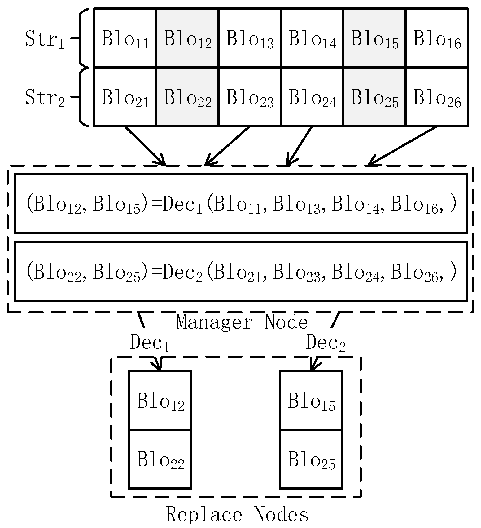
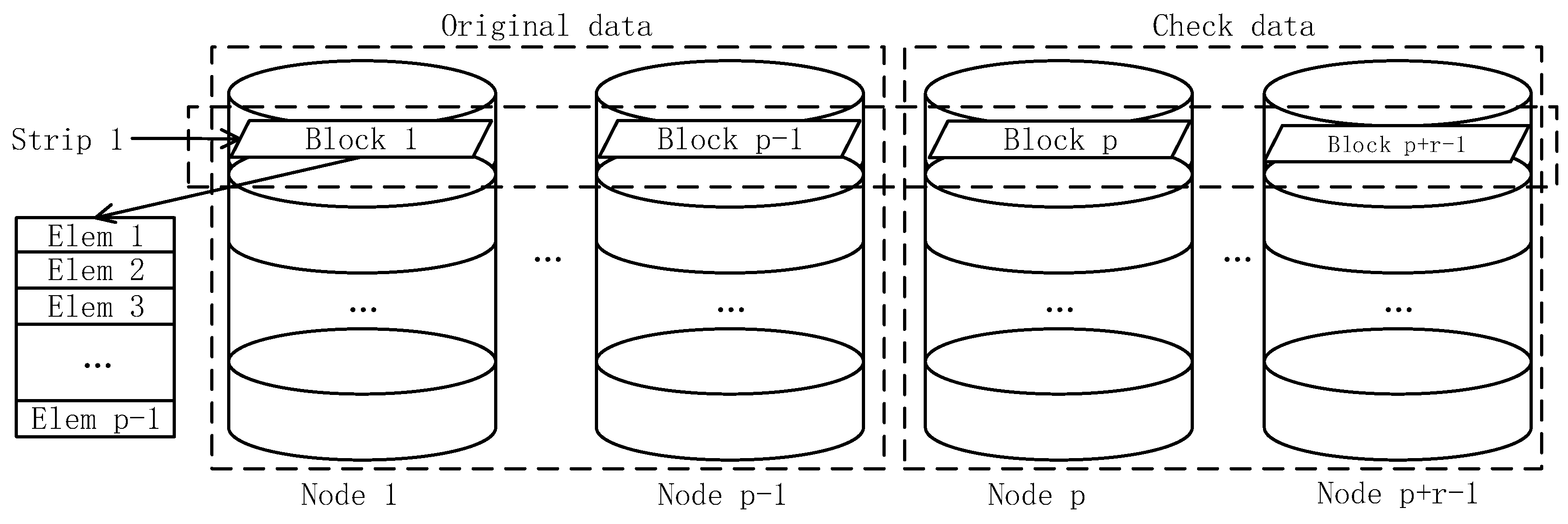
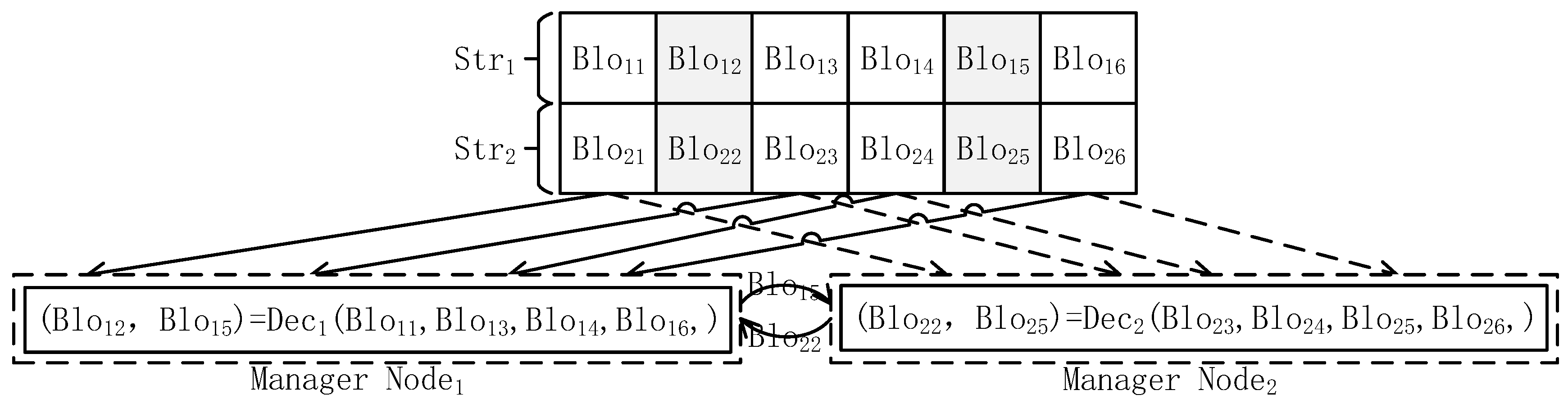
3.1. DCRS Repair Model

To begin with, we need to introduce the definition of the generalized RDP code, since the DCRS repair model is based on this code.
Definition 1.
Generalized RDP Code. There are r check columns in the generalized RDP code and the i-th raw element in the k-th ( 0 k r 1 ) check column is the XOR value of the i-th diagonal elements, which has a k slope. The data in the stripe is stored in a ( p 1 ) × ( p + r 1 ) matrix, where p is a prime number.
d i , p 1 + k = ( j = 0 p 1 d < i k j > , j )    s . t .    0 k r 1
It is assumed that the data in the cluster is stored as a minimum repair unit, and the data blocks in the stripe are distributed based on respective storage nodes. According to Formula (1), each data block is divided into p 1 elements, which have an equal size. Therefore, the data in one stripe can be represented as a two-dimensional matrix of ( p 1 ) × ( p + r 1 ) , where p 1 is the number of data columns, and r is the number of check columns. The logical relationship of data partitioning is shown in Figure 3.
Formula (1) implies that when there are k ( k r ) damaged nodes, the system can calculate the data block information of the damaged nodes through the decoding operation. There is a detailed reconstruction scheme for the generalized RDP code in [14], which we do not repeat here.

3.2. DCRS Repair Scheme

3.2.1. DCRS Repair Algorithm

Through the research on the SMR scheme and the MMR scheme, we can find that the SMR scheme has the problem of repairing bottlenecks; meanwhile, the MMR scheme has the problem of excessive consumption of network bandwidth. In order to solve these problems, we have proposed a DCRS scheme by analyzing the advantages and disadvantages of the SMR scheme and the MMR scheme. When p = 5 and r = 2 , the repair model of DCRS is shown in Figure 4. Unlike SMR, the manager nodes in DCRS are played by multiple replacement nodes, and data repair can be simultaneously performed in multiple manager nodes, which speeds up repairs. Compared with the MMR, each manager node in the DCRS cooperatively repairs the data, and the data in the stripe is transmitted only once, thus reducing the network traffic inside the system.
When multiple nodes simultaneously fail, the DCRS scheme can repair the data blocks of the failed nodes in a distributed manner. Repair node r ( 0 < r k ) repairs stripe i k + r . When the stripe repair is completed, the repair node distributes the repaired data blocks to the corresponding nodes. The details are shown in Algorithm 1.
Algorithm 1. DCRS Repair Algorithm
Input: Damaged Node ID Dn = { N x 1 , N x k } ; Output: Replace node Rn = { N y 1 , N y k }
  Step 1: Initialize the data. Obtain the damaged nodes’ ID and the replaced nodes’ ID. Then, the number of damaged stripes N is obtained from the NameNode, and initialize the number of repaired stripes i = 0 ;
  Step 2: Get the repair nodes’ status. The status of each repair node is obtained from the NameNode. R n [ j ] may have two states, working or free, represented by false and true respectively;
  Step 3: Data is allocated to repair nodes. If the state of R n [ j ] is true, data blocks of the s t r i p e [ i ] are obtained from the surviving nodes, and transmitted to R n [ j ] node, then change the state of R n [ j ] to false;
  Step 4: Data reorganization of repair nodes. When the damaged stripe is received by R n [ j ] , the corrupted data blocks in the stripe are restored. Then, change the state of R n [ j ] to true;
  Step 5: Data distribution of repair nodes. If data blocks reparation in s t r i p e [ i ] are completed, the repaired m -th data block is distributed to Node R n [ m ] , then i = i + 1 ;
  Step 6: Program judgment. If i N , the repair is complete; otherwise, return to Step 2.

3.2.2. DCRS Repair Efficiency

In DCRS, in order to improve the repair efficiency, a multi-node cross-repair method is used. In this paper, the variables and meanings used in the efficiency analysis process are shown in Table 1.
In DCRS, the total repair time is expressed as Formula (2):
T = α T a l l T + β T a l l R
Since data transmission and calculation are performed in a parallel method, T a l l T and T a l l R can be collectively represented by m , T s t r i p T , T s t r i p R and k . T a l l T includes the stripe transmission time and the repaired blocks’ transmission time, as shown in Formula (3):
{ T a l l T = m k T s t r i p e T + m ( k 1 ) T b l o c k T T a l l R = m k T s t r i p e R
In Formula (3), the transmission time T s t r i p e T and repair time T s t r i p e R are related to the number of transmitted data blocks and γ i , as shown in Formula (4):
{ T s t r i p e R = k T b l o c k R = i = 0 k 1 γ i T b l o c k R i T s t r i p e T = ( n + r k ) T b l o c k T + ( k 1 ) T b l o c k T
From Formula (2) to Formula (4), the total system time can be expressed by Formula (5):
T = ( m ( n + r k ) k + α m ( k 1 ) ) T b l o c k T + m k i = 0 k 1 γ i T b l o c k R i
Similarly, the total system time of SMR and MMR can be expressed by Formula (6) and Formula (7):
C _ T = m ( n + r k ) T b l o c k T + m k T b l o c k R
D _ T = m ( n + r k ) k T b l o c k T + m k i = 0 k 1 γ i T b l o c k R i
When multiple nodes fail, data transmission and data repair are performed in parallel. When stripe i is repairing, stripe i + 1 has begun to transfer data blocks. With the rapid development of CPU computing power, the transmission time is much longer than the repair time when performing data repair, i.e., T X T > > T X R . Therefore, Formulas (5)–(7) can be simplified as Formulas (8)–(10):
T = ( m ( n + r k ) k + m ( k 1 ) ) T b l o c k T
C _ T = m × ( n + r k ) × T b l o c k T
D _ T = m × ( n + r k ) × k × T b l o c k T
Then, we can get an interesting conclusion through Formulas (8), (9), and (10) in the following:
T C _ T = ( m ( n + r k ) k + m ( k 1 ) ) T b l o c k T m ( n + r k ) T b l o c k T = 1 k + k 1 n + r k
Equation (1) indicates that k r , and the failed columns do not exceed the data columns in cloud storage, therefore k < n .
Thus, T / C _ T can be expressed as:
T C _ T < 1 k + k 1 n < 1 + k 1 k = 1
Moreover, T D _ T < 1 can be proved by the same method.
In summary, the DCRS can reduce system repair time.

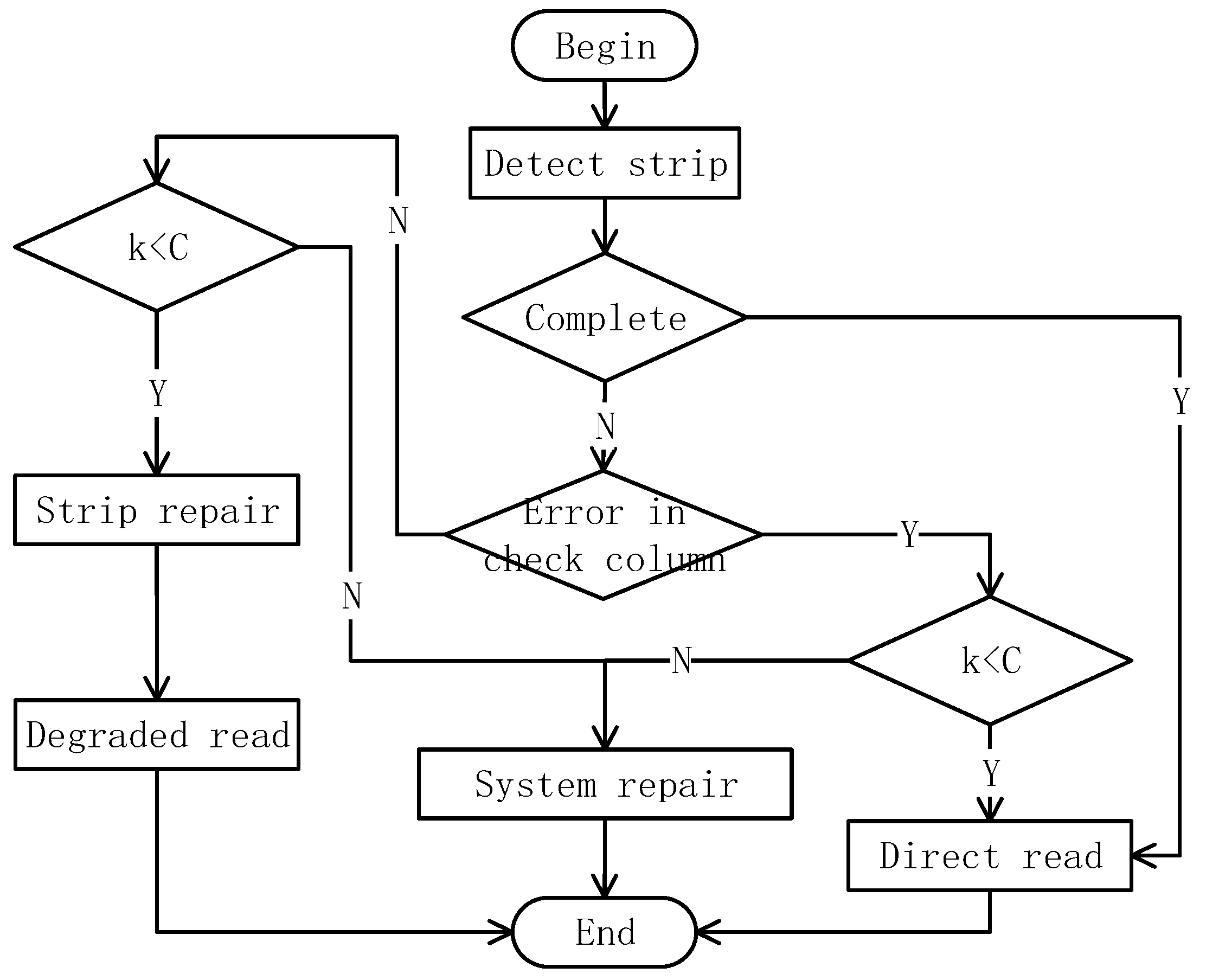
3.3. DCRS Repair Trigger Mechanism

The DCRS can repair the system when multiple node failures. However, if the repair operation is frequently performed, the system will waste a lot of computing resources and network bandwidth. If the repair operation is performed when the number of damaged node reaches the maximum tolerable number, the data will face a risk of unrecoverable data when a failed node is added into the repair process. At the same time, the hysteresis of the repair will also bring delay to the data read operation. Therefore, DCRS uses a repair trigger mechanism.
In DCRS, the read operation of data blocks can be divided into direct read operation and degraded read [22] operation. Data blocks in the desired stripe are complete, and can be read directly by users in the first method. Furthermore, there are some erroneous data blocks in the required stripe that need to be repaired before being read in the second method. The repair trigger mechanism is shown in Figure 5:
In the repair trigger mechanism of the DCRS, the system will detect whether the required stripe is complete after the users initiate a read request. If there are no damaged data blocks or there are some damaged data blocks but their positions are on the check columns, the stripe can be read directly. If there are some damaged data blocks and their positions are on the data columns, the stripe repair operation is performed at the replacement nodes, and the stripe is returned to users when the repair is finished. In the case of degraded reading, if the number of damaged data blocks in the stripe reaches the threshold C   { 0 < C < r } , the system repair will be triggered, and the damaged nodes will be repaired. Then, we will analysis the effectiveness of the trigger mechanism.
In a storage system, data can’t be repaired when k > r occurs. We can set the probability of node failure as p . When the node failure trigger mechanism is adopted, the repair of the damaged node begins at k = c * , and the irreparable probability of the system is P u s e ; if the node repair trigger mechanism is not used, the damaged node repair starts at k = r , and the irreparable probability of the system is P u s e ¯ . When the system performs a node repair trigger mechanism, the probability of node repair failure in the two cases can be shown in Formula (11) and Formula (12), respectively:
P u s e = 1 i = 0 r c * C n c * i p i ( 1 p ) n c * i
P u s e ¯ = 1 ( 1 p ) n r
Thus:
p u s e p u s e ¯ = 1 i = 0 r c * C n c * i p i ( 1 p ) n c * i 1 ( 1 p ) n r = 1 ( 1 p ) n r i = 0 r c * 1 C n c * i p i ( 1 p ) n c * i 1 ( 1 p ) n r = 1 i = 0 r c * 1 C n c * i p i ( 1 p ) n c * i 1 ( 1 p ) n r < 1
After the above-mentioned analysis, we can draw a conclusion that the repair trigger mechanism can effectively reduce the risk of irreparable data.

4. Performance Evaluation

The simulation compares SMR, MMR, and the DCRS in terms of degraded read delay, system repair delay, and system repair risk.

4.1. Simulation Platform and Parameters

The hardware that was used in the experimental platform was an Inter(R) Core(TM)2 Duo CPU T5670 @ 1.80GHz, memory (RAM) 2.00GB. The cluster related information is shown in Table 2.

4.2. Degraded Read Delay

In a storage cluster based on the generalized RDP code, in order to satisfy the user’s request, the system performs a degraded read operation when there are some erroneous data blocks in the read stripe. It preferentially decodes the erroneous data blocks on the stripe. In order to clearly describe the problem, we set the number of stripes requested by the user as five at a time. We set the waiting delay (total time from user request to receive) using the SMR to 1, and then normalize the simulation data. The average waiting delay in SMR, MMR, and the DCRS is shown in Figure 6. Among them, the abscissa indicates the number of damaged nodes, and the ordinate indicates the waiting delay.
Figure 6 shows that SMR has a longer delay in the three schemes, and the DCRS has the least delay. Since SMR uses centralized repair, a single repair node causes a repair bottleneck when the data is repaired, and this in turn makes a higher system repair delay. MMR adopts a distributed repair method to avoid the bottleneck of the system repair. However, this repair method increases the network throughput, and still leads to a higher delay. DCRS instead adopts a distributed and cross repair to avoid the repeated transmission of data, which reduces the network throughput. Therefore, DCRS can reduce the latency of degraded read, and thereby improve the system’s overall performance.

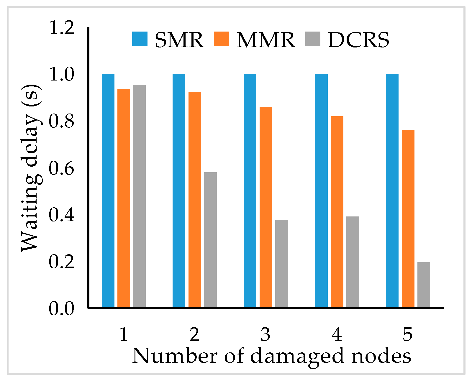
4.3. System Repair Delay

In order to ensure the system’s normal working, fault nodes will be repaired when there are quantities of fault nodes. We compare the repair delay of SMR, MMR, and the DCRS when the nodes have different storage sizes (the number of stripes in the node), as shown in Table 3.
Table 3 shows that using DCRS can reduce the system repair delay. Compared with MMR and SMR, DCRS adopts a distributed-cross repair method to repair the damaged nodes at multiple replacement nodes. After that, the repaired data is distributed to different replacement nodes. In this case, the redundant transmission of data is avoided and system network throughput is reduced, so DCRS can be used to speed up the system repair process.

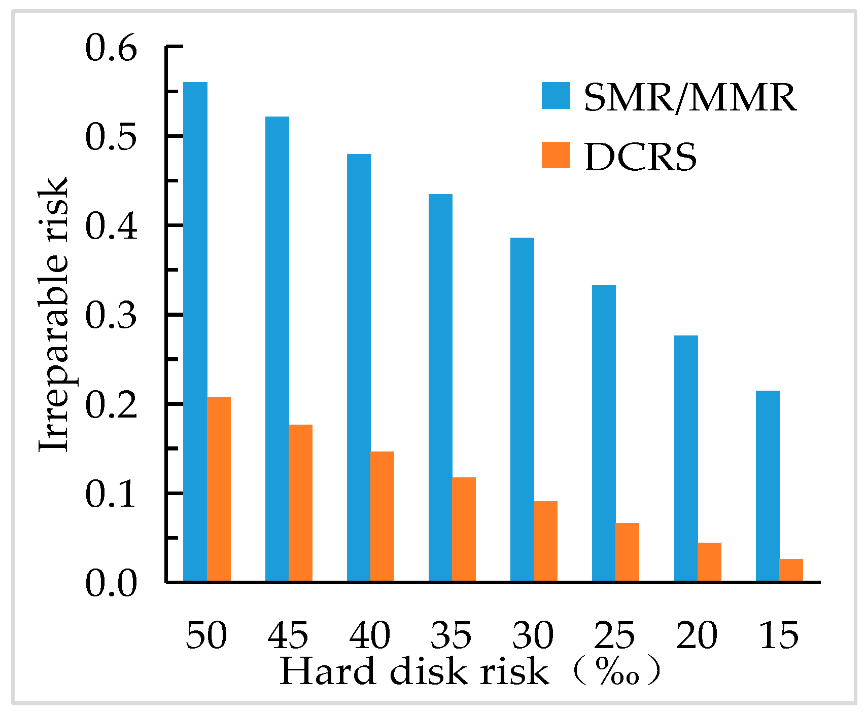
4.4. System Repair Risk

In DCRS, a repair trigger mechanism is added, and when the number of damaged data blocks reaches the threshold, a repair operation is triggered. The system’s irreparable risk index is shown in Figure 7. In this simulation, the number of check nodes is five; SMR and MMR do not use the repair trigger mechanism, the DCRS uses the repair trigger mechanism, and the threshold is four.
As the hard disk risk index (hard disk damage probability) decreases, the system risk decreases. As can be seen in Figure 7, the irreparable risk of DCRS is significantly lower than the SMR and MMR schemes. In DCRS, when the system is repaired, the number of damaged nodes is smaller than the number of check columns, so that the system can be repaired when other damaged nodes are added to the system during the reparation process. The simulation results are consistent with the inference of Section 3.3. Therefore, the repair trigger mechanism can reduce the system irreparable risk and increase the system security.

5. Conclusions

This paper studies the repair scheme of multi-nodes failure in cloud storage. A DCRS scheme is proposed for the problem of the excessive consumption of network bandwidth and bottlenecks during system repair. In this scenario, the data repair process is spread to various replacement nodes, and each damaged stripe is only transmitted to a unique replacement node. The node repairs the damaged data blocks and distributes them to various replacement nodes for storage. This repair scheme has a good effect on reducing the network throughput and eliminating the repair bottlenecks. At the same time, a new repair trigger mechanism is proposed in this scheme, which can reduce the risk of repair failure caused by the increase of new damage nodes when the system is repaired, thus improving the system availability. Simulation results have shown that it can reduce the system repair delay and improve the system availability.

Author Contributions

G.X. conceived and designed the study, and wrote the manuscript. H.Y. provided the technical advice. J.S. revised the manuscript. All authors have read and approved the final manuscript.

Funding

The research leading to these results has received funding from the Henan Foundation and Frontier Research Project (152300410212).

Conflicts of Interest

The authors declare no conflict of interest.

References

  1. Lv, Y.; Duan, Y.; Kang, W.; Li, Z.; Wang, F.Y. Traffic Flow Prediction with Big Data: A Deep Learning Approach. IEEE Trans. Intell. Transp. Syst. 2015, 16, 865–873. [Google Scholar] [CrossRef]
  2. Xu, Q.; Wang, W.Y.; Yong, K.L.; Aung, K.M.M. Building a Robust and Efficient Middleware for Geo-replicated Storage Systems. In Proceedings of the 2015 International Conference on Cloud Computing Research and Innovation (ICCCRI), Singapore, 26–27 October 2015; pp. 148–155. [Google Scholar] [CrossRef]
  3. Du, M.; Wang, Q.; He, M.; Weng, J. Privacy-preserving Indexing and Query Processing for Secure Dynamic Cloud Storage. IEEE Trans. Inf. Forensics Secur. 2018, 13, 2320–2332. [Google Scholar] [CrossRef]
  4. Yang, T.; Wang, M.; Zhang, Y.; Zhao, Y.; Pen, H. HDFS Differential Storage Energy-saving Optimal Algorithm in Cloud Data Center. Chin. J. Comput. 2018, 1–14. Available online: http://kns.cnki.net/kcms/detail/11.1826.TP.20180303. 1344.010.html (accessed on 8 January 2019). (In Chinese).
  5. Fu, Y.; Zhang, M.; Chen, K.; Feng, D. Proofs of Data Possession of Multiple Copies. J. Comput. Res. Dev. 2014, 51, 1410–1416. (In Chinese) [Google Scholar] [CrossRef]
  6. Moniz, H.; Leitão, J.; Dias, R.J.; Gehrke, J.; Preguiça, N.; Rodrigues, R. Blotter: Low latency transactions for geo-replicated storage. In Proceedings of the 26th International Conference on World Wide Web, Perth, Australia, 3–7 April 2017; pp. 263–272. [Google Scholar] [CrossRef]
  7. Yan, X.; Zhang, D.; Zhang, B. Cloud Storage Fault-tolerant Research Based on Adaptive Switching Scheme Between Replication and Erasure Codes. J. Electr. Syst. Inf. Technol. 2016, 39, 1–6. (In Chinese) [Google Scholar] [CrossRef]
  8. Lin, X.; Wang, Y.; Pei, X.; Xu, F. GRC: A High Fault-Tolerance and Low Recovery-Overhead Erasure Code for Multiple Losses. J. Comput. Res. Dev. 2014, 51, 172–181. (In Chinese) [Google Scholar]
  9. Liu, C.; Wang, Q.; Chu, X.; Leung, Y.W. G-CRS: GPU Accelerated Cauchy Reed-Solomon Coding. IEEE Trans. Parallel Distrib. Syst. 2018, 7, 1484–1498. [Google Scholar] [CrossRef]
  10. Xu, Q.Q.; Xi, W.Y.; Yong, K.L.; Jin, C. CRL: Efficient Concurrent Regeneration Codes with Local Reconstruction in Geo-Distributed Storage Systems. J. Comput. Sci. Technol. 2018, 33, 1140–1151. [Google Scholar] [CrossRef]
  11. Wan, W.; Yang, W.; Chen, Y. Research on MDS Array Codes in Fault-Tolerant Storage Systems. J. B. Univ. Post. Telecommun. 2014, 37, 75–79. (In Chinese) [Google Scholar] [CrossRef]
  12. Bao, X.; Lu, P.; Yang, L. Recognition of RS Coding Based on Galois Field Fourier Transform. J. Univ. Electr. Sci. Technol. Chin. 2016, 45, 30–35. (In Chinese) [Google Scholar]
  13. Hou, H.; Lee, P.P.C. A New Construction of EVENODD Codes with Lower Computational Complexity. IEEE Commun. Lett. 2018, 22, 1120–1123. [Google Scholar] [CrossRef]
  14. Huang, Z. Research on MDS Array Codes in Fault-Tolerant Storage Systems. J. Huazhong Univ. Sci. Technol. 2016, 5. (In Chinese) [Google Scholar]
  15. Ding, S.; Tong, X.; Chen, Y.; Ye, B. Bandwidth-Aware Node Repair Optimization for Distributed Storage System Based on Simple Regenerating Code. J. Soft. 2017, 28, 1940–1951. (In Chinese) [Google Scholar] [CrossRef]
  16. Zhong, R.; Liu, C.; Wang, C.; Xiang, F. Cost-Aware Data Reliability Provision Algorithm for the Cloud Providers. J. Soft. 2014, 25, 1874–1886. (In Chinese) [Google Scholar] [CrossRef]
  17. Xu, Q.; Xi, W.; Yong, K.L.; Jin, C. Concurrent regeneration code with local reconstruction in distributed storage systems. In Advanced Multimedia and Ubiquitous Engineering; Springer: Berlin/Heidelberg, Germany, 2016; pp. 415–422. [Google Scholar] [CrossRef]
  18. Zhang, J.; Li, S.; Liao, X. REDU: Reducing redundancy and duplication for multi-failure recovery in erasure-coded storages. J. Supercomput. 2016, 72, 3281–3296. [Google Scholar] [CrossRef]
  19. Pei, X.; Wang, Y.; Ma, X.; Xu, F. Efficient in-place update with grouped and pipelined data transmission in erasure-coded storage systems. Future Gener. Comput. Syst. 2017, 69, 24–40. [Google Scholar] [CrossRef]
  20. Prakash, N.; Abdrashitov, V.; Medard, M. The Storage vs Repair-Bandwidth Trade-off for Clustered Storage Systems. IEEE Trans. Inf. Theory 2018. [Google Scholar] [CrossRef]
  21. Su, Y.S. Pliable Fractional Repetition Codes for Distributed Storage Systems: Design and Analysis. IEEE Trans. Commun. 2018, 66, 2359–2375. [Google Scholar] [CrossRef]
  22. Li, P.; Jin, X.; Stones, R.J.; Wang, G.; Li, Z.; Liu, X.; Ren, M. Parallelizing degraded read for erasure coded cloud storage systems using collective communications. IEEE Trustcom/BigDataSE/ISPA 2016, 1272–1279. [Google Scholar] [CrossRef]
Figure 1. Transmission and Repair Process in Single Manager Repair (SMR).
Information 10 00020 g001
Figure 2. Transmission and Repair Process in Multi Manager Repair (MMR).
Information 10 00020 g002
Figure 3. Logical Relationship of Data Partitioning.
Information 10 00020 g003
Figure 4. Distributed-Cross Repair Solution (DCRS) Repair Model.
Information 10 00020 g004
Figure 5. Repair Trigger Mechanism.
Information 10 00020 g005
Figure 6. Degraded Read Latency.
Information 10 00020 g006
Figure 7. System Unrepair Risk.
Information 10 00020 g007
Table 1. Variables and their meanings in efficiency analysis.
VariablesMeanings
T b l o c k Total time to transfer and repair a data block
T s t r i p e Total time to transfer and repair a stripe
T X T Required transmission time, and x = { block , stripe , all } , same as below
T X R Required repair time
T b l o c k R i Required time for node[i] to repair a single data block
T Total time to system repair
r Number of check columns
m Number of stripes
n Number of data columns
k Number of failed columns (number of failed nodes)
γ i Repair node[i]’s computational performance parameters
Table 2. Cluster Parameter Table.
NameParameter
Network bandwidth (Mbit/s)1000
Number of nodes30
Number of data nodes16
Number of check nodes5
Number of stripes (per node)20
Data block size (MB)64
Table 3. Repair Delay Comparison.
Storage SizeSMR (s)MMR (s)DCRS (s)MMR/SMRDCRS/SMR
10119.9291.7723.160.76530.1931
20239.47182.4845.650.76200.1906
30358.83274.0669.280.76380.1931
40478.72365.5191.540.76350.1912
50598.20456.48114.670.76310.1917
60719.80547.46138.360.76060.1922
70836.05638.03160.270.76310.1917

