An Improved Reversible Image Transformation Using K-Means Clustering and Block Patching


Abstract
:1. Introduction
2. Related Work
2.1. Feature Extraction for Image Blocks Matching
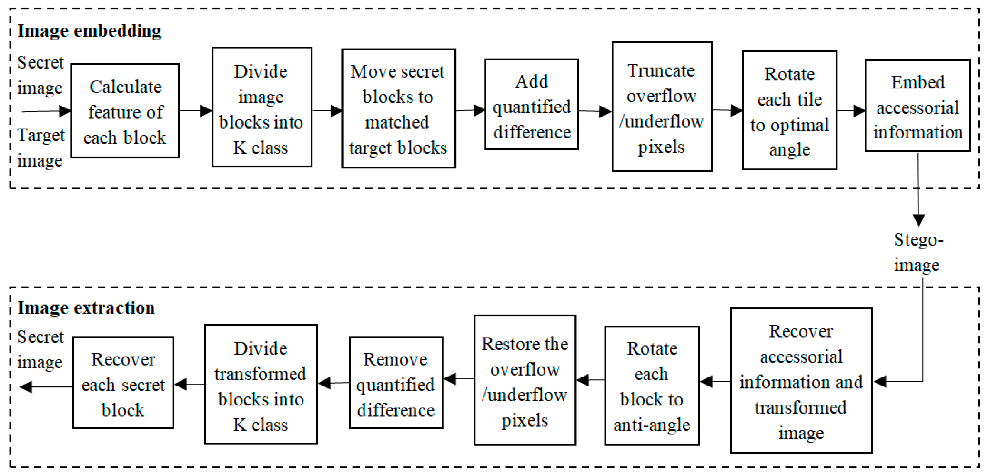
2.2. Reversible Shift and Rotate Transformation
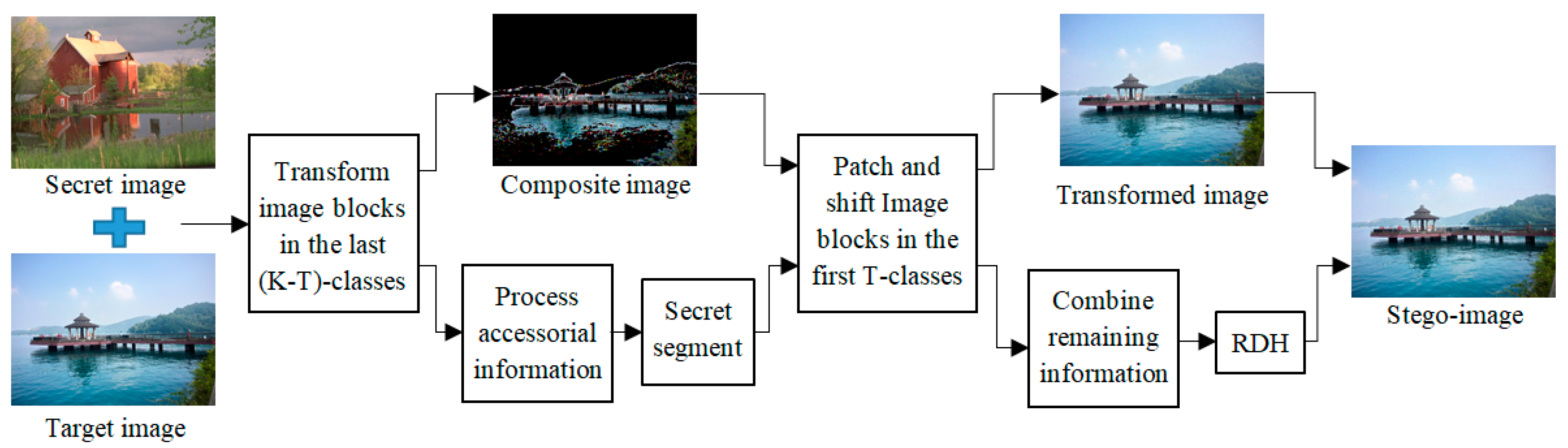
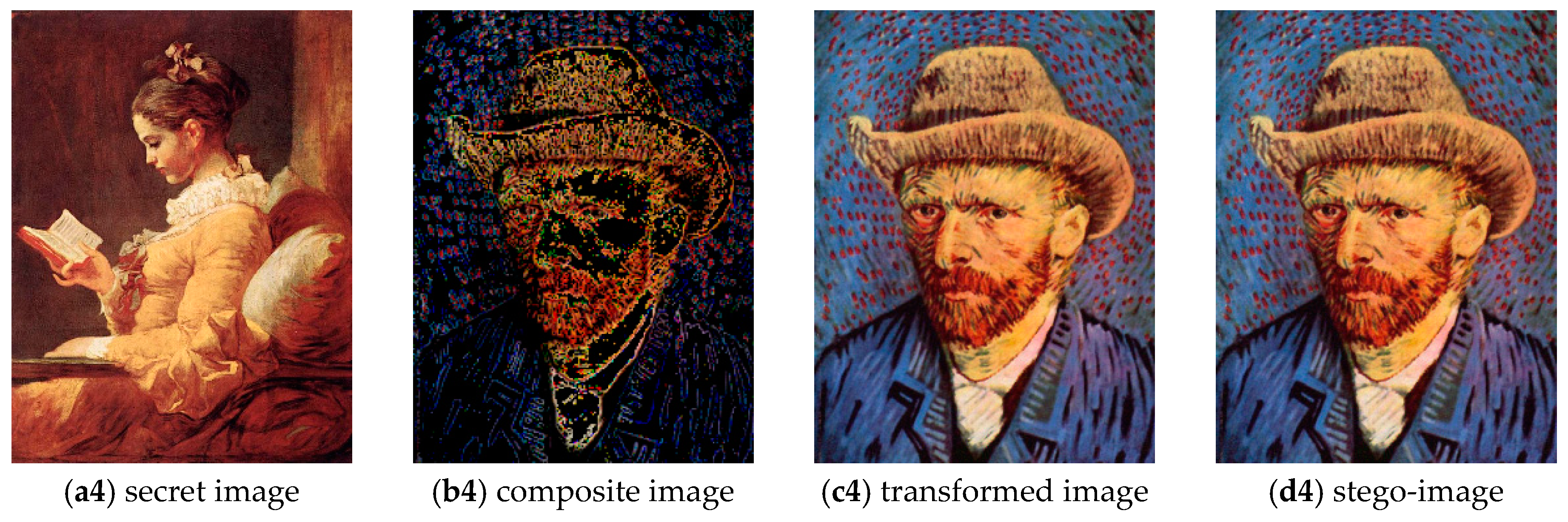
3. The Proposed Method
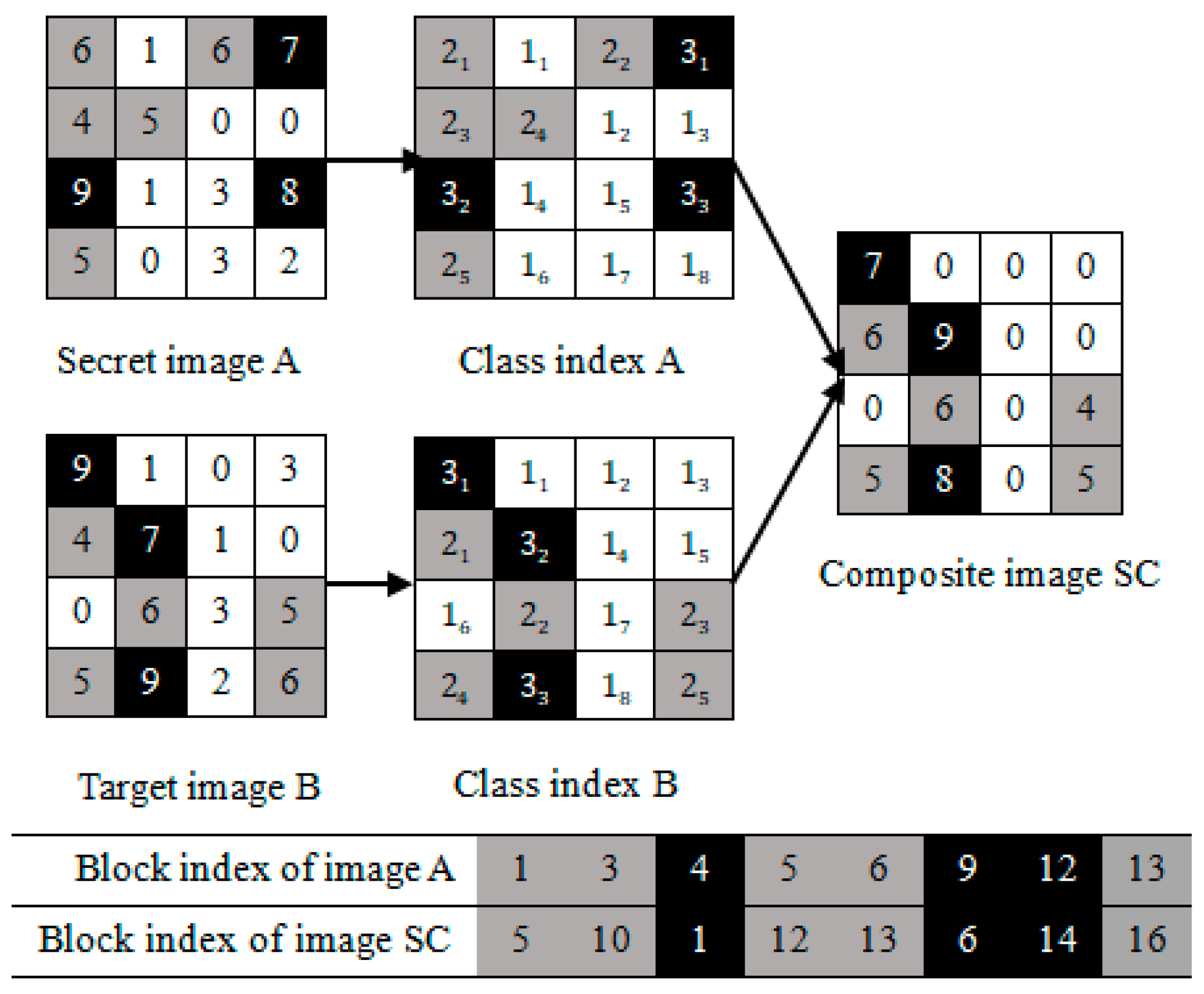
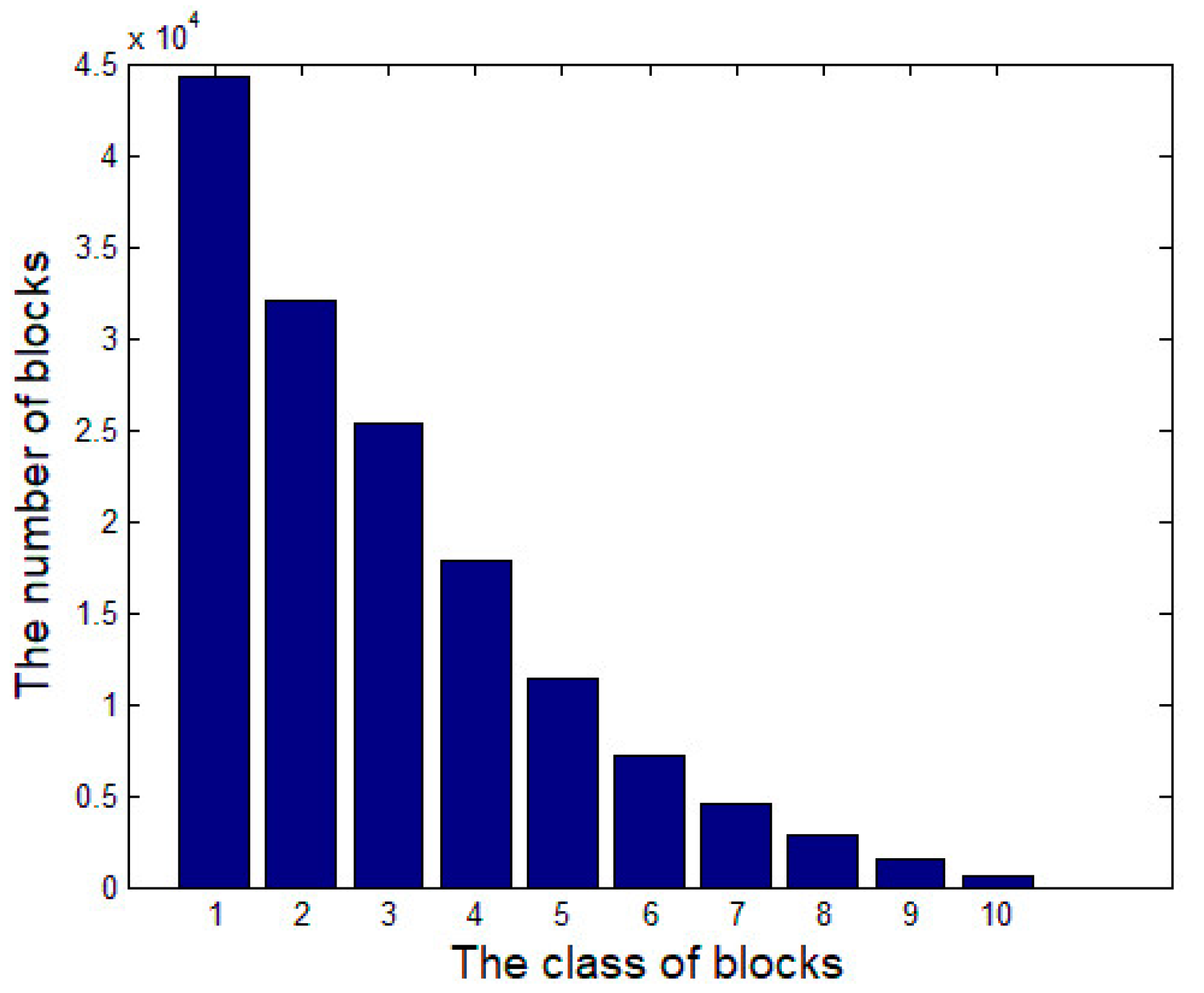
3.1. Image Blocks Matching of the Last (K-T)-Classes
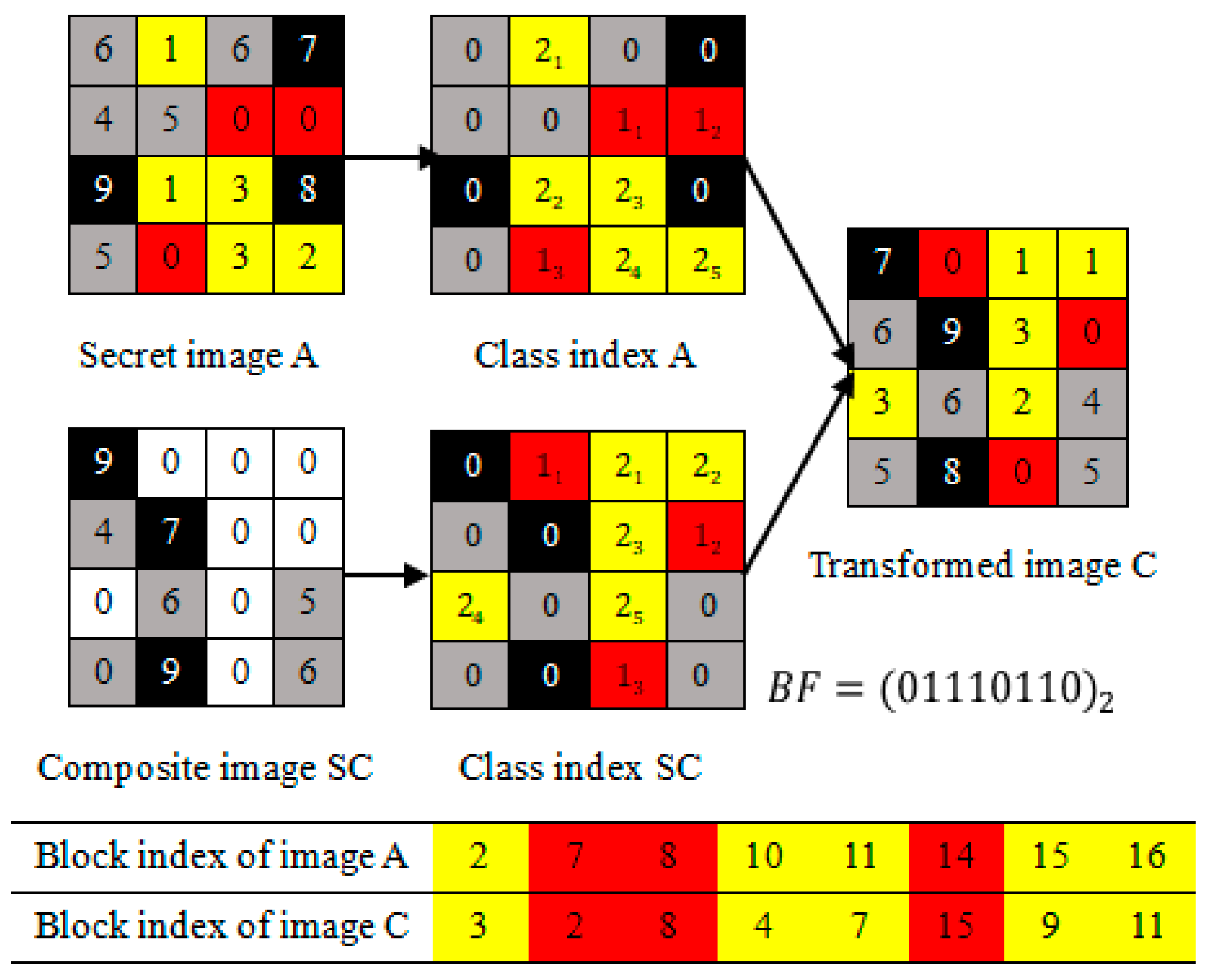
3.2. Image Blocks Patching of the First T-Classes
- (1)
- The first-3 image blocks of the ascending sequence belong to class 1; they are labeled as “red”;
- (2)
- The last-5 image blocks of the ascending sequence belong to class 2; they are labeled as “yellow”.
3.3. Algorithm Explaining of the Proposed Method
| Algorithm 1 Stego-image creation |
| Input: A secret image, target image and secret key sk. |
| Output: A stege-image. |
| 1: for each color channel of secret and target images do |
| 2: Divide each color channel of two images into non-overlapping blocks. |
| 3: for each block in these images do |
| 4: Calculate the mean and SD of each block. |
| 5: Cluster secret blocks into K classes by K-means clustering according to their SDs, and classify target blocks into K classes according to their SDs, the scanning order and the classes volumes of secret image. Assign a class index for each color channel of two images. |
| 6: for each block in the last (K-T)-classes do |
| 7: Match image blocks having same class index. |
| 8: Shift pixel values with Equations (3)–(5) and (7), and rotate each block with the optimal angel. |
| 9: Record the , and as the parameters for restoring the image. |
| 10: Replace the target image blocks with the corresponding transformed blocks in the last (K-T)-classes, and generate the composite image. |
| 11: Compress the AI , which brings from the last (K-T)-classes transformation, and divide them into and . |
| 12: for each block in the first T-classes do |
| 13: Distribute a class index to these blocks of secret and composite images by , then patch the secret image blocks into current position of composite image to hide . |
| 14: Shift pixel values with Equations (3)–(5) and (7), and rotate patched blocks with the optimal angel. |
| 15: Compress new parameters including , and as . |
| 16: Replace the target image blocks with the corresponding transformed blocks. |
| 17: Combine three color channels to generate the final transformed image. |
| 18: Combine and to obtain AI, and use secret key sk to encrypt the information, then embed the encrypted sequence into the transformed image by RDH method. |
| 19: return The stego-image. |
| Algorithm 2 Secret image recovery |
| Input: A stege-image and secret key sk. |
| Output: A secret image. |
| 1: Extract the encrypted sequence and recover the transformed image by RDH method. |
| 2: Decrypt and decompress the sequence to obtain and . |
| 3: for each color channel of transformed images do |
| 4: Divide each color channel of transformed image into non-overlapping blocks. |
| 5: for each block in the image do |
| 6: Calculate the mean and SD of each block. |
| 7: Obtain class index A according to , and classify the transformed blocks into K classes by their SDs and class index A, then generate , class index SC and B. |
| 8: for each block in the first T-classes do |
| 9: Rotate the block in the reverse direction and shift pixel values according to . |
| 10: Rearrange the transformed blocks in the first T-classes to generate the composite image by the mapping relation between class indexes A and SC. |
| 11: Combine and to obtain . |
| 12: for each block in the last (K-T)-classes do |
| 13: Rotate the block in the reverse direction and shift pixel values according to . |
| 14: Reassign the transformed blocks in the last (K-T)-classes by the mapping relation between class indexes A and B. |
| 15: return The original secret image. |
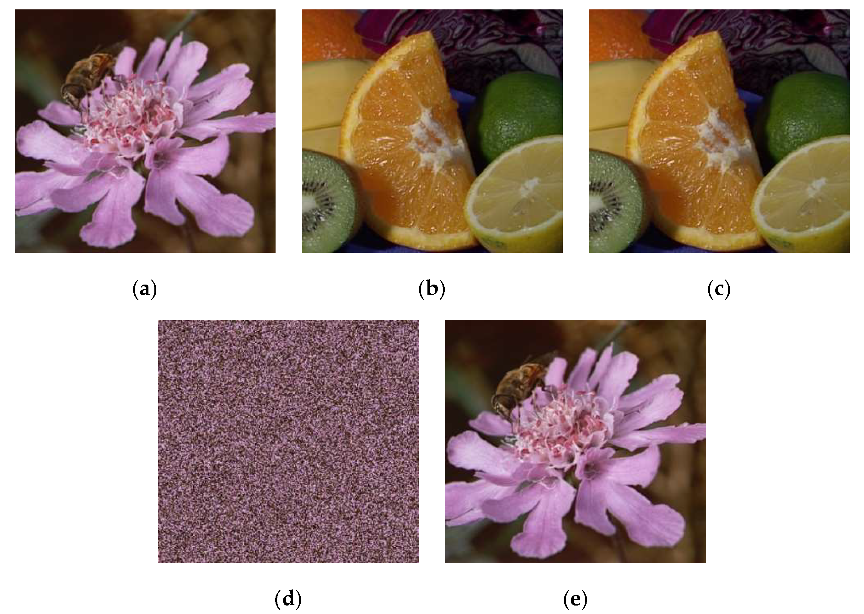
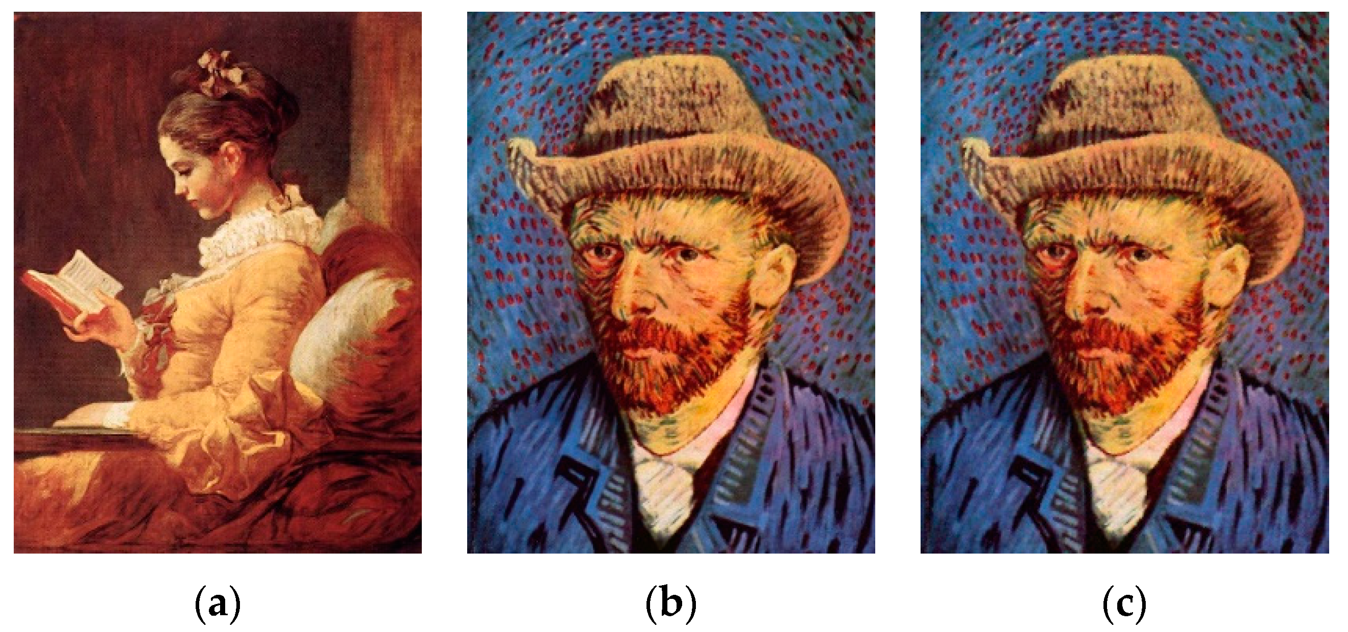
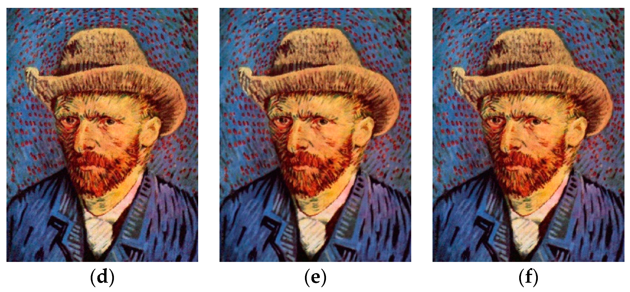
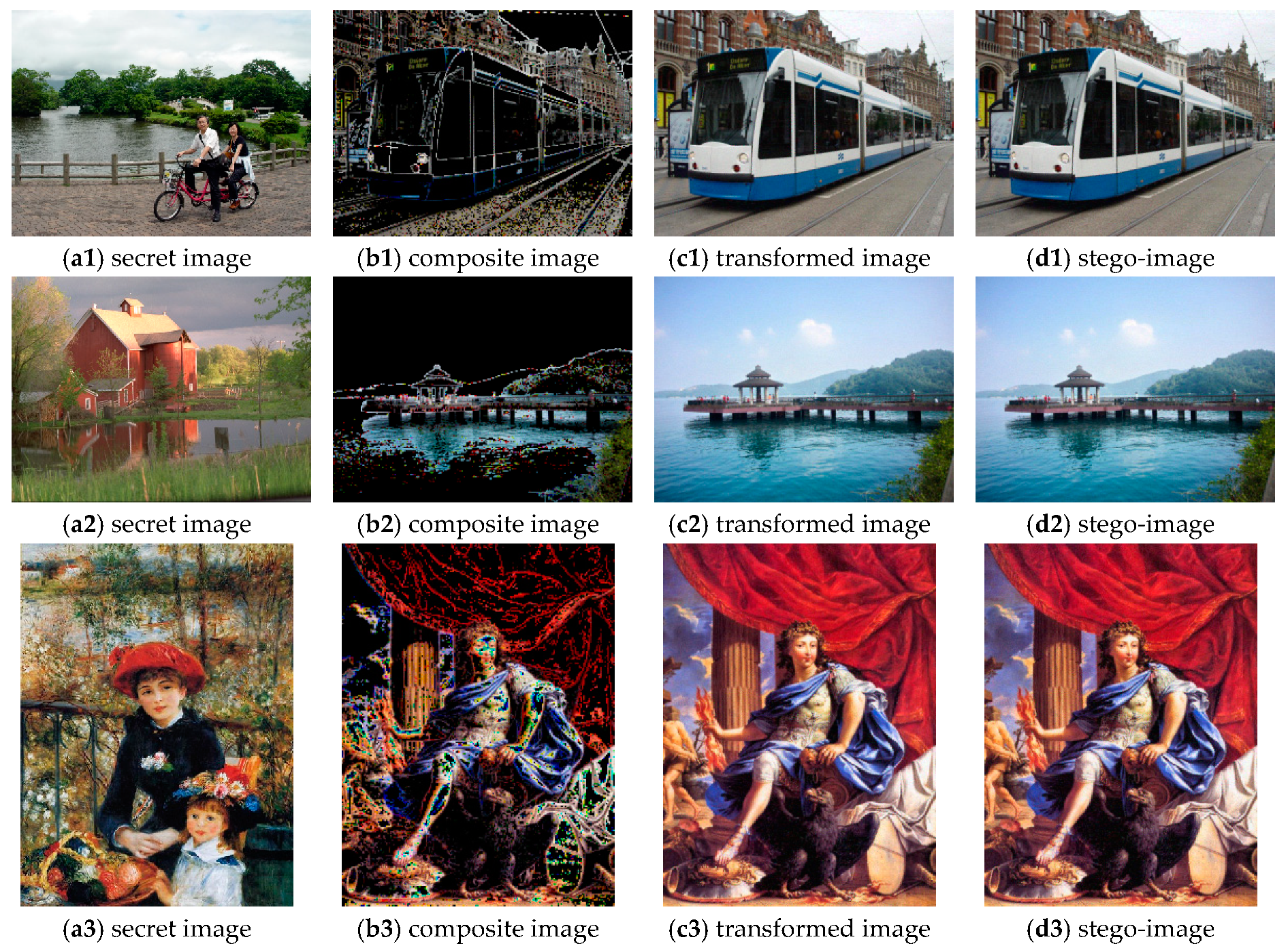
4. Experimental Results
4.1. Performance Indexes
4.2. Parameter Settings
4.3. Comparison the Proposed Method with Previous Methods
4.3.1. Performance Comparison
4.3.2. Feature Comparison
5. Conclusions
Author Contributions
Funding
Conflicts of Interest
References
- Chan, C.; Cheng, L. Hiding Data in Images by Simple LSB Substitution. Pattern Recognit. 2004, 37, 469–474. [Google Scholar] [CrossRef]
- Hong, W. Efficient Data Hiding Based on Block Truncation Coding Using Pixel Pair Matching Technique. Symmetry 2018, 10, 36. [Google Scholar] [CrossRef]
- Lu, T. Interpolation-based hiding scheme using the modulus function and re-encoding strategy. Signal Process. 2018, 142, 244–259. [Google Scholar] [CrossRef]
- Wu, K.; Wang, C.M. Steganography using reversible texture synthesis. IEEE Trans. Image Process. 2015, 24, 130–139. [Google Scholar] [PubMed]
- Hayat, U.; Azam, N. A novel image encryption scheme based on an elliptic curve. Signal Process. 2019, 155, 391–402. [Google Scholar] [CrossRef]
- Fridrich, J.; Goljan, M.; Du, R. Lossless data embedding new paradigm in digital watermarking. EURASIP J. Appl. Signal Process. 2002, 2, 185–196. [Google Scholar] [CrossRef]
- Tian, J. Reversible data embedding using a difference expansion. IEEE Trans. Circuits Syst. Video Technol. 2003, 13, 890–896. [Google Scholar] [CrossRef]
- Sachnev, V.; Kim, H.; Nam, J.; Suresh, S.; Shi, Y. Reversible Watermarking Algorithm Using Sorting and Prediction. IEEE Trans. Circuits Syst. Video Technol. 2009, 19, 989–999. [Google Scholar] [CrossRef]
- Pakdaman, Z.; Saryazdi, S.; Nezamabadi-pou, H. A prediction based reversible image watermarking in Hadamard domain. Multimed. Tools Appl. 2017, 76, 8517–8545. [Google Scholar] [CrossRef]
- Zhang, X. Reversible data hiding in encrypted images. IEEE Signal Process Lett. 2011, 18, 255–258. [Google Scholar] [CrossRef]
- Hong, W.; Chen, T.; Wu, H. An improved reversible data hiding in encrypted images using side match. IEEE Signal Process Lett. 2012, 19, 199–202. [Google Scholar] [CrossRef]
- Zhou, J.; Sun, W.; Dong, L.; Liu, X.; Au, O.; Tang, Y. Secure reversible image data hiding over encrypted domain via key modulation. IEEE Trans. Circuits Syst. Video Technol. 2016, 26, 441–452. [Google Scholar] [CrossRef]
- Yin, Z.; Niu, X.; Zhang, X.; Tang, J.; Luo, B. Reversible data hiding in encrypted AMBTC images. Multimed. Tools Appl. 2018, 77, 18067–18083. [Google Scholar] [CrossRef]
- Ma, K.; Zhang, W.; Zhao, X.; Yu, N.; Li, F. Reversible Data Hiding in Encrypted Images by Reserving Room Before Encryption. IEEE Trans. Inf. Forensics Secur. 2013, 8, 553–562. [Google Scholar] [CrossRef]
- Cao, X.; Du, L.; Wei, X.; Meng, D.; Guo, X. High Capacity Reversible Data Hiding in Encrypted Images by Patch-Level Sparse Representation. IEEE Trans. Cybern. 2016, 46, 1132–1143. [Google Scholar] [CrossRef] [PubMed]
- Yang, C.; Ouyang, J.; Harn, L. Steganography and authentication in image sharing without parity bits. Opt. Commun. 2012, 285, 1725–1735. [Google Scholar] [CrossRef]
- Lai, I.; Tsai, W. Secret-Fragment-Visible Mosaic Image–A New Computer Art and Its Application to Information Hiding. IEEE Trans. Inform. Forensics Secur. 2011, 6, 936–945. [Google Scholar]
- Lee, Y.; Tsai, W.A. New Secure Image Transmission Technique via Secret-Fragment-Visible Mosaic Images by Nearly Reversible Color Transformations. IEEE Trans. Circuits Syst. Video Technol. 2014, 24, 695–703. [Google Scholar]
- Hou, D.; Zhang, W.; Yu, N. Image camouflage by reversible image transformation. J. Vis. Commun. Image Represent. 2016, 40, 225–236. [Google Scholar] [CrossRef]
- Zhang, W.; Wang, H.; Hou, D.; Yu, N. Reversible Data Hiding in Encrypted Images by Reversible Image Transformation. IEEE Trans. Multimed. 2016, 18, 1469–1479. [Google Scholar] [CrossRef]


| Block Size | Transformed Image (RMSE) | Stego-Image (RMSE) | AI (bpp) |
|---|---|---|---|
| 10.725 | 14.990 | 0.852 | |
| 13.001 | 13.310 | 0.488 | |
| 16.000 | 16.060 | 0.227 | |
| 17.918 | 17.947 | 0.134 |
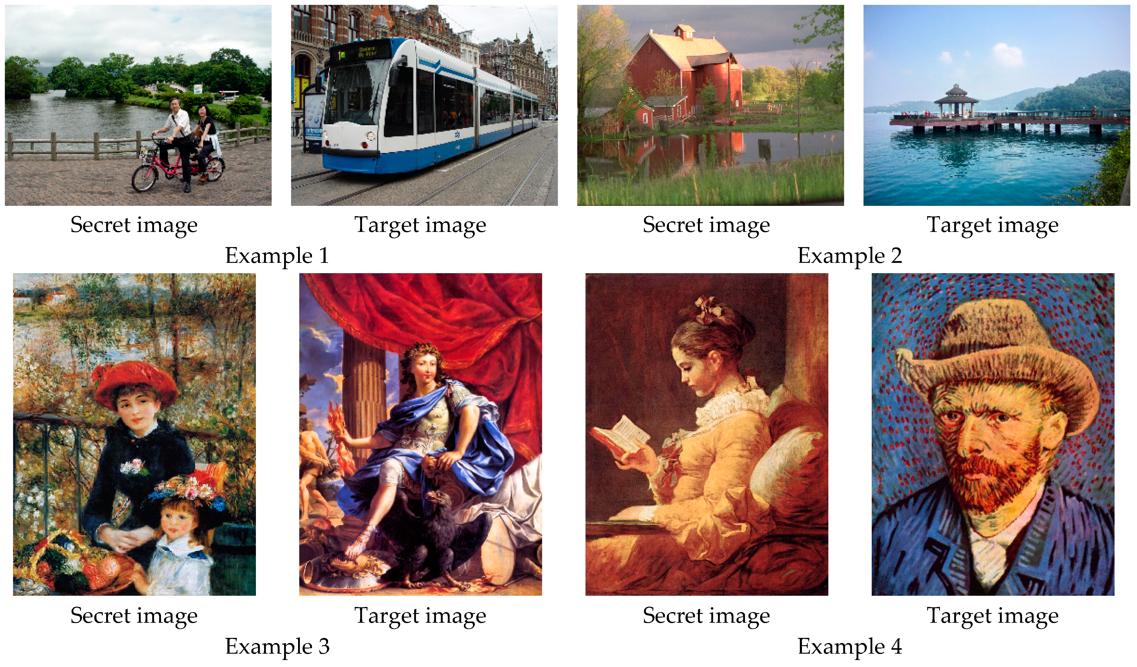
| Example 1 | Example 2 | Example 3 | Example 4 | Average | ||||||
|---|---|---|---|---|---|---|---|---|---|---|
| AI | RMSE | AI | RMSE | AI | RMSE | AI | RMSE | AI | RMSE | |
| 0.852 | 18.868 | 0.738 | 12.841 | 1.070 | 16.631 | 0.973 | 11.139 | 0.908 | 14.870 | |
| 0.541 | 19.131 | 0.494 | 13.023 | 0.584 | 16.756 | 0.495 | 11.242 | 0.529 | 15.038 | |
| 0.564 | 19.959 | 0.495 | 13.756 | 0.573 | 17.251 | 0.489 | 11.762 | 0.530 | 15.621 | |
| 0.552 | 21.050 | 0.475 | 14.777 | 0.561 | 18.426 | 0.471 | 12.442 | 0.515 | 15.682 | |
| 0.555 | 19.143 | 0.484 | 12.982 | 0.599 | 16.927 | 0.499 | 11.249 | 0.652 | 15.075 | |
| 0.540 | 19.111 | 0.490 | 12.971 | 0.586 | 17.369 | 0.493 | 11.250 | 0.627 | 15.175 | |
| 0.542 | 19.068 | 0.490 | 12.994 | 0.573 | 17.704 | 0.496 | 11.237 | 0.620 | 15.175 | |
| 0.540 | 20.138 | 0.510 | 13.023 | 0.578 | 17.900 | 0.496 | 11.248 | 0.618 | 15.251 | |
| Methods | Stego-Image (RMSE) | Stego-Image (SSIM) | AI |
|---|---|---|---|
| Hou et al.’s method | 17.653 | 0.593 | 0.647 |
| Proposed method | 17.178 | 0.602 | 0.527 |
| Method | Reversibility | High Capacity | Image Expansion | High Security |
|---|---|---|---|---|
| Zhou et al.’s method | No | No | No | Yes |
| Wu et al.’s method | Yes | No | Yes | No |
| Yang et al.’s method | Yes | Yes | No | Yes |
| Lai et al.’s method | Yes | Yes | Yes | Yes |
| Lee et al.’s method | No | Yes | No | Yes |
| Proposed method | Yes | Yes | No | Yes |
© 2019 by the authors. Licensee MDPI, Basel, Switzerland. This article is an open access article distributed under the terms and conditions of the Creative Commons Attribution (CC BY) license (http://creativecommons.org/licenses/by/4.0/).
Share and Cite
Zhong, H.; Chen, X.; Tian, Q. An Improved Reversible Image Transformation Using K-Means Clustering and Block Patching. Information 2019, 10, 17. https://doi.org/10.3390/info10010017
Zhong H, Chen X, Tian Q. An Improved Reversible Image Transformation Using K-Means Clustering and Block Patching. Information. 2019; 10(1):17. https://doi.org/10.3390/info10010017
Chicago/Turabian StyleZhong, Haidong, Xianyi Chen, and Qinglong Tian. 2019. "An Improved Reversible Image Transformation Using K-Means Clustering and Block Patching" Information 10, no. 1: 17. https://doi.org/10.3390/info10010017
APA StyleZhong, H., Chen, X., & Tian, Q. (2019). An Improved Reversible Image Transformation Using K-Means Clustering and Block Patching. Information, 10(1), 17. https://doi.org/10.3390/info10010017