Review

A Review of System Strength and Inertia in Renewable-Energy-Dominated Grids: Challenges, Sustainability, and Solutions

1
Department of Electrical Engineering, Engineering Institute of Technology, West Perth, WA 6005, Australia
2
Department of Information Systems, Durban University of Technology, Greyville, Durban 4001, South Africa
3
Electrical Engineering Discipline, School of Electrical Engineering, Computing and Mathematical Sciences, Curtin University, Bentley, Perth, WA 6102, Australia
*
Authors to whom correspondence should be addressed.
Challenges 2025, 16(1), 12; https://doi.org/10.3390/challe16010012
Submission received: 29 November 2024 / Revised: 6 February 2025 / Accepted: 7 February 2025 / Published: 10 February 2025

Abstract

:
The global shift towards renewable energy sources (RESs) presents significant challenges to power grid stability, particularly in grids with a high penetration of inverter-based resources (IBRs). The shift to RESs is critical to improve planetary health; however, grids must remain reliable and affordable throughout the transition to ensure economies can thrive and critical infrastructure remains secure. Towards that goal, this review introduces the issues of declining system strength and inertia in such grids, illustrated by case studies of curtailment measures employed by system operators in the deregulated electricity markets of Australia, Ireland, and Texas. In these high-IBR markets, curtailment has become essential to maintain system security. This paper presents the current mitigation strategies used by system operators and discusses their limitations. In addition, the paper presents a comprehensive review and analysis of current research on system strength and inertia estimation techniques, grid modelling approaches, and advanced inverter control, with a particular focus on virtual inertia. Future research directions and recommendations are outlined based on the identified gaps. These recommendations are intended to minimise system operator intervention and RES curtailment while maintaining reliable and affordable grid operation. The insights presented in this paper provide a framework to guide system operators, researchers, and policymakers toward enhancing grid stability while targeting 100% RES.

1. Introduction

The transition toward renewable energy sources (RESs) is driven by climate goals and the declining cost of RES technology such as wind and solar [1]. Firmed wind and solar are currently the lowest levelised cost of energy [2]. Electricity markets in Australia and Ireland have ambitious targets for RES integration, aiming for over 80% by the year 2030 [3]. Other markets globally are beginning to adopt similar goals. However, as RES levels rise, grid stability faces new challenges. Historically, power grids were dominated by synchronous generation (SG). SGs inherently provide system strength and inertia through their normal operation. These qualities are now rapidly declining as large SGs are decommissioned to make way for RESs.
Wind and solar RESs are connected asynchronously through inverters. This configuration is referred to as inverter-based resources (IBRs). IBRs rely on phase-locked loop (PLL) algorithms for grid synchronisation, which can fail if the voltage waveform is not purely sinusoidal [4]. The reduction in SGs decreases system strength and inertia, leading to reduced voltage and frequency stability margins, increasing the risk of IBR synchronisation loss [5]. Modern IBRs are of sufficient size that the loss of a solar or wind farm may destabilise other generating units on the grid.
This review explores the technical challenges and emerging solutions for maintaining system stability in high-IBR grids. It specifically covers system strength and inertia evaluation methods, mitigation techniques—such as grid-forming inverters (GFMIs), synchronous condensers (SynCons), flexible AC transmission systems (FACTS), and advances in grid modelling methods. The primary contribution of this review paper is the development of a framework of recommendations tailored for policymakers and system operators (SOs) worldwide.
Prior reviews of system strength and inertia [6,7,8,9,10,11] have provided valuable insights. This paper aims to build on these reviews with an updated review of recent case studies and mitigation strategies. Aljarrah et al.’s review [6] focused its future direction on grid-following inverter (GFLI) PLL improvement and a study on grid-forming inverters (GFMIs). This paper builds upon the existing body of knowledge in the literature by offering the following specific contributions:
  • An analysis of recent events and SO market intervention in the deregulated and weakly interconnected electricity markets of Australia, Ireland, and Texas.
  • A critical review of current mitigation techniques including synchronous condensers and ancillary services.
  • An evaluation of research gaps in system strength and inertia estimation methods, high-IBR grid modelling, and non-linear GFMI output current control techniques.
The paper is organised into six main sections. Section 2 provides a brief definition for system strength and inertia. Section 3 explores the impact of high levels of IBRs on system strength and stability. Case studies and SO interventions are reviewed in Section 4. Section 5 is a review of current mitigation approaches. Section 6 provides a review of the recent literature for the areas of system strength and inertia estimation, grid modelling, and advanced GFLI/GFMI control. A summary of the contribution and limitations in the recent literature along with a framework of novel recommendations for SOs and policy makers is presented in Section 7, followed by concluding remarks.

2. Understanding System Strength and Inertia

2.1. Definitions and Key Concepts

The Australian Energy Market Commission (AEMC) defines system strength as “a characteristic of an electrical power system that relates to the size of the change in voltage following a fault or disturbance on the power system” [12]. Historically, with power grids dominated by SGs, system strength was an inherent characteristic of the grid. With increasing IBR levels, this is no longer the case. Recent studies have sought to better quantify system strength [7,10,11]. Hosseinzadeh et al. [13] defined power system strength as the sensitivity of the node voltage to changes in current from generators or IBRs connected to that node.
Inertia is a measure of SG’s tendency to remain at constant speed despite disturbances. SG’s rotor speed and grid frequency are closely related in power grids. Inertia is highly beneficial for frequency stability and does not require measurement or control to function as it is a physical property of the SG rotor’s spinning mass. As IBR levels increase and replace SGs, grid inertia is diminishing and becoming increasingly variable due to the intermittent nature of RESs [14].

2.2. Impact of IBR Generation

Today’s grid operates as a hybrid of IBRs and synchronous machines. Alkhazim et al. [15] highlighted that this hybridisation, especially on the demand side, caused several distribution grid issues, including reverse power flow on feeders and the mis-operation of protection systems. Nearly all IBRs use GFLI control structures [16], relying on PLLs to synchronise with the grid voltage waveform. Voltage distortions, imbalances, and oscillations often cause PLL malfunctions, resulting in unscheduled IBR synchronisation loss. Aljarrah et al. [6] discussed the risk of further cascading grid failures as a result of this synchronisation loss.
IBRs use Maximum Power Point Tracking (MPPT) and operate at unity power factor [17,18], meaning that they supply active power without reactive power provision. This form of GFLI control limits IBRs to acting as current sources, offering no support for system strength or inertia.

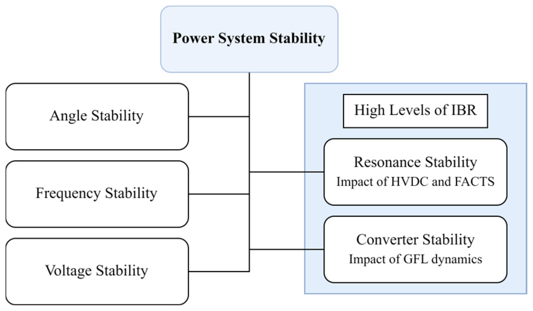
3. System Strength and Inertia Challenges

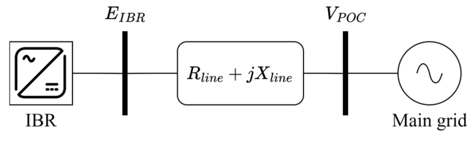
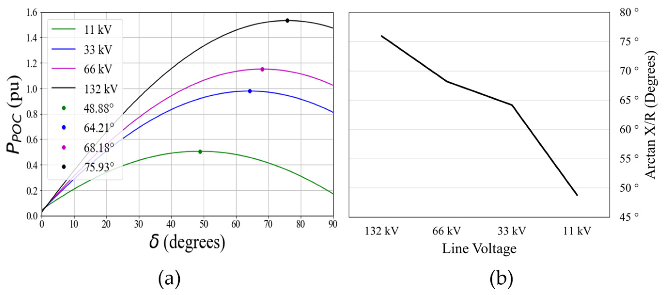
3.1. System Strength Issues

Reduced system strength leads to increased harmonic distortion levels, sub-synchronous oscillations (SSOs), increased magnitude of voltage dips and swells, and incorrect operation of protection systems and capacitor banks [19]. Weak grids are more vulnerable to voltage instability, with oscillation below system frequency that often arise from control loop interactions among IBRs after voltage disturbances. This phenomenon was demonstrated in [20].

Voltage Stability

High levels of IBRs increase the risk of voltage collapse [21,22]. Voltage stability should be considered for both steady-state and transient conditions. In steady state, insufficient reactive power can lead to voltage instability in heavy loading conditions. Figure 1 shows the voltage stability limits with varying grid power factor levels. Operation under the red dashed lines is unstable and may result in voltage collapse. Intermittent RESs cause sudden power fluctuations, increasing potential voltage instability. This is most notable on grid segments with poorly regulated voltage profiles [23,24].
Transient stability is becoming increasingly important considering the low short circuit ratio (SCR) conditions introduced by increasing levels of IBRs [25,26,27]. SCR is a measure of the fault current available at a node, providing a measure of voltage stiffness. SCR is covered in detail in Section 6.1.1. GFLI control algorithms used in IBRs pose three transient stability challenges [25,28]:
  • IBRs cause a drop in SCR making the node voltage more susceptible to rapid current changes caused by transient conditions.
  • GFLI algorithms demonstrate suboptimal performance under faulted conditions. IBR plant tripping during faulted conditions is a significant problem as shown by the examples provided in Section 4.3.
  • The tripping in item 2 can lead to further voltage instability and entire plant tripping.
These issues are covered in more detail with case studies in Section 4.

3.2. Inertia Issues

3.2.1. Frequency Stability

High IBR penetration raises the Rate of Change of Frequency (RoCoF) during contingencies, like generation plant trips. In SG-based grids, sufficient time is supplied by inertia for the primary controls (see Figure 2), such as a SG speed governor, to adjust. The RoCoF is defined by (1).
R o C o F = Δ f Δ t = Δ P p . u . f 0 2 H
where H is the inertia constant in seconds, Δ p p . u . is the generator trip amount in p.u., and f o is the system frequency prior to the trip. The value for RoCoF, therefore, will increase as inertia, H, decreases. This concept is illustrated in Figure 2.
In lower inertia levels, the RoCoF is faster, increasing the risk of sympathetic tripping, potentially followed by cascading grid outages. IBR sympathetic tripping occurs when the system’s RoCoF, following a generator trip, causes PLL phase jump errors [29].
The standard RoCoF limit for steam turbines is 2 Hz/s [7], posing two problems:
  • A greater than 2 Hz/s RoCoF may trigger the protection-based tripping of additional SGs.
  • The depth of the frequency nadir (see Figure 2) may trigger involuntary load shedding as discussed in depth in [30].

3.2.2. Angle Stability

Inertia levels in the grid are positively correlated with angle stability. High levels of SG result in well-damped frequency and phase angle deviations. A decrease in SGs with a corresponding increase in IBRs will reduce this damping effect as highlighted in [31].
Many IBRs are connected to distribution networks at voltages from 11 kV to 66 kV. According to [32], line resistance plays a more critical role in this type of connection.
The maximum power transfer for a generator on a line is typically determined as below:
P P O C = E g e n V P O C X l i n e s i n δ
where PPOC is the power flow at the point of coupling, and the value of R l i n e is ignored using the assumption that lines are dominated by reactance. Using this formula, maximum power transfer occurs at δ = 90 ° . In low X/R ratio lines, this simplification is no longer valid. Equation (3), adapted from [33], is a revised power transfer formulation for low X/R lines. It remains an approximation, assuming short line conditions and ignoring source impedance. For GFLIs, source impedance is constant and low, making this approach valid. However, this is not the case with the frequently varying impedances generated by GFMI. The parameters for (3) are shown graphically in Figure 3. Z and θ are defined in (4) and (5). With (3), V P increases while V Q decreases, diminishing the well-defined P δ and Q V relationships found in high-voltage SG-dominated grids [34].
P P O C = E I B R V P O C Z c o s θ z δ V P O C 2 Z c o s θ Z
Z = R 2 + X 2
θ Z = t a n 1 X R
Figure 4a illustrates Equation (3) for typical resistance and reactance values found in aluminium lines at the displayed voltage levels. Sending end voltage is assumed to be 1 p.u., and receiving end voltage is at 0.95 p.u. for a 20 km aluminium line. The impact on maximum power transfer and stability margins both show a significant reduction. Figure 4b shows that the impedance angle drops sharply from 66 kV.
Long transmission lines used for IBRs in remote locations have higher impedance values, which also causes stability issues. A study on the impact of X/R ratios and high impedance on GFMI stability is provided in [35].

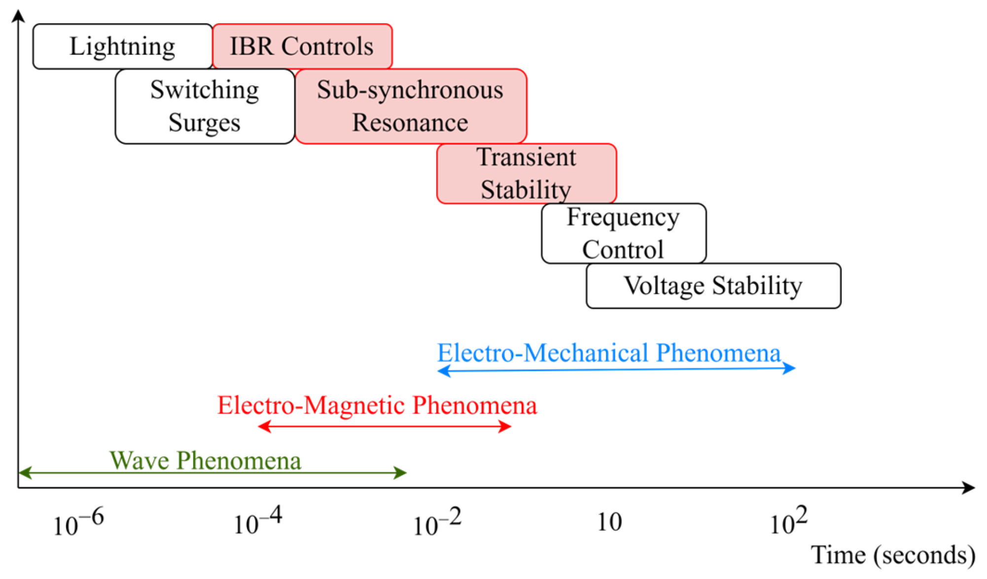
3.2.3. Emerging Stability Categories

Stability categories in SG-dominated grids were formalised in the seminal work [36]. Hatziargyriou et al. [37] proposed two new stability categories considering the modern high-IBR grid:
  • Resonance stability, related to the impact of HVDC and FACTS devices.
  • Converter stability, relating to the impact of GFLI (both current and voltage source).
The stability categories for the high-IBR grid are illustrated in Figure 5.
Feedback loop interactions between HVDC and FACTS devices with other grid components can lead to unintended sub-synchronous resonance (SSR) [38]. Power electronic (PE)-based control algorithms interact with transmission line parameters at specific frequencies. This form of resonance can lead to the damage of SG rotors if their resonant frequency aligns with the interaction frequencies. Surinkaew et al. [39] showed that these issues are time-consuming to diagnose and expensive to fix.
Control stability issues occur when delays in IBR control loops cause undesired negative damping. This results in sustained oscillation, which causes further instability in other IBRs. This control instability is a result of the software defined dynamics found in IBRs [40]. The study in [41] showed that GFMIs can cause similar control instability issues in stiff grids. This issue is confirmed in [42]. In that paper [42], the authors proposed and validated an active susceptance loop to increase GFMI robustness across a range of SCR values from ultra weak (SCR = 1) to stiff (SCR = 38.5).
As power systems continue to evolve towards 100% IBRs, it is likely that new categories of stability will be uncovered.

4. Case Studies from Regions with High Renewable Energy

Australia, Ireland, and Texas are all deregulated electricity markets. They are also weakly interconnected systems as illustrated in Figure 6. The weak interconnection rating for Ireland and Texas is due to their asynchronous DC connections to the UK in Ireland’s case and the broader US for Texas. Weak interconnection in Australia is due to three state regions, Queensland, South Australia and Tasmania, relying upon a single synchronous interconnector. Queensland and South Australia have an AC and DC interconnector pair to the Australia’s National Electricity Market (NEM), while Tasmania relies solely upon its DC interconnector.
For context, NEM has a generation capacity of 40 GW serving roughly 25 million people, Electricity Reliability Council of Texas (ERCOT) has a generation capacity of 90 GW serving roughly 26 million people, and Ireland’s Single Electricity Market (SEM) has a generation capacity of 10 GW serving roughly 6.5 million people.

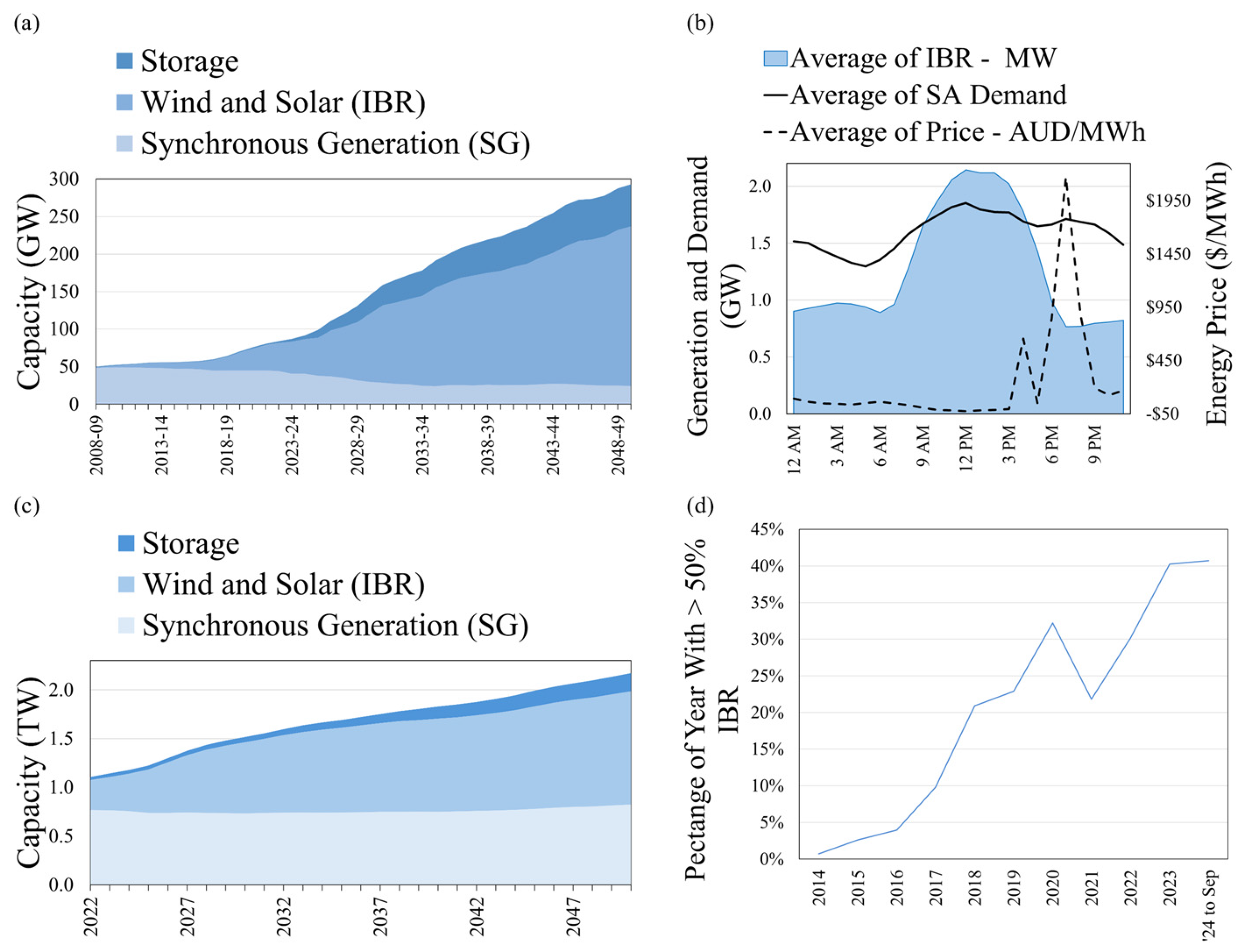
4.1. IBR Penetration Levels

IBR penetration is growing rapidly on each of the above-mentioned grids. Figure 7a shows projected IBR growth to 2050 in Australia, based on data from the Australian Energy Market Operator’s (AEMO’s) Integrated System Plan [43]. IBRs in South Australia already exceed the region’s demand, see Figure 7b, based on a dataset from Open Electricity [44]. ERCOT currently has 71% IBRs [45], putting it on par with levels in Australia and Ireland.
Similar IBR growth is projected in the United States and Ireland, shown in Figure 7c,d, based on data from [46,47]. Market deregulation in these regions hinders coordinated power system security planning due to a lack of incentives for an orderly transition from SGs to IBRs.
The impact of rapid IBR growth was highlighted in AEMO’s 2023 Inertia Report [48]. In the report, inertia shortfalls for Queensland (1.66 GWs), South Australia (500 MWs), and Tasmania (2.5 GWs) were declared. These shortfalls are based on the projections highlighted in Figure 7a. The assumptions in the report rely on major infrastructure projects such as new interconnections and so these shortfalls may be understated if projects are delayed.

4.2. System Operator Interventions

SOs use computerised dispatch optimisation engines to manage system security while dispatching the lowest cost electricity to consumers. AEMO uses a linear programming-based engine called NEMDE to solve the dispatch optimisation problem for the NEM. NEMDE does this in close to real time as the NEM operates in 5-min intervals [49]. AEMO manages system security and technical limitations using constraints in NEMDE. These constraints prevent dispatch solutions that would violate the grid’s technical limitations. These technical limitations include voltage and frequency stability. SOs can also intervene in normal market operations where it is deemed technically necessary. To highlight the growing problem of declining system strength, this section explores recent SO market interventions and dispatch constraint updates to maintain system security as IBRs grow.
On 24 September 2024, AEMO directed Snowy Hydro, the Australian government-owned operator of the Snowy Mountains hydro-electric scheme, to synchronise and operate their Murray 2 hydro turbine assets in SynCon mode [50]. This intervention was issued under market notice 119269 in accordance with National Electricity Rules (NER) clause 4.8.9 (a1) due to low system strength in the area. In the 2023 System Strength Report [51], AEMO identified shortfalls for the New South Wales, Queensland, and Tasmania regions.
To manage system strength shortfalls in the Irish SEM, EirGrid, and SONI, the Irish Transmission SOs (TSOs) have introduced two additional constraints to their generation dispatch engine [52]:
  • Maximum system non-synchronous penetration (SNSP) limit of 75%.
  • A minimum number of conventional units on (MUON) of seven units.
While EirGrid and SONI’s approach achieves the required system strength outcome, this action also increases fossil fuel consumption while limiting RESs. This is not a desirable outcome and is, therefore, an opportunity to develop new techniques to manage the objectives.
Due to the high levels of wind energy in Ireland, EirGrid has changed the maximum acceptable RoCoF as part of their DS3 program, first proposed in [53]. RoCoF changed from the previous setting of 0.5 Hz/s to a new value of 1 Hz/s. In 2023, TSOs in Ireland curtailed or constrained approximately 1795 GWh of IBRs to maintain system security [54].
ESIG forecasted that IBRs in Texas will reach over 92 GWs by 2025 [55]. The ESIG report goes on to highlight ERCOT’s use of generic transmission constraints (GTCs) to limit transmission flows from grid regions considered “weak” for system security protection.
Table 1 provides a summary of SO intervention to maintain system security and the outcome of that intervention in terms of RES curtailment.

4.3. System Strength and Inertia Events

There have been numerous reports of SSOs in the Murray region of the NEM. AEMO published data from the Red-Cliffs Transmission Station (RCTS) [58] showing a 16.81 Hz oscillation following a line trip in the area. Figure 8 shows the SSO FFT. Oscillation in the 15–20 Hz frequency range is known to be related to GFLI control dynamics [59]. There are four solar farms located in the West Murray region. Numerous studies [39,60,61] have analysed similar oscillation events in high-IBR grids. The West Murray region oscillations have led to heavy RES curtailment due to low system strength, as well as significant delays and cancellations of new RES developments.
In June 2022, ElectraNet, the state transmission provider in South Australia, directed Port Augusta Renewable Energy Park (PAREP) to disconnect shortly after energising the plant for commissioning [62]. PAREP is a combined wind and solar farm project (210 MW and 107 MW, respectively) located near Port Augusta in South Australia. ElectraNet observed voltage flicker on the network and made the direction to avoid voltage instability in the region.
The 2022 Odessa Disturbance occurred in Texas on 4 June 2022 [63]. This was a recurrence of an event at the same location nearly a year earlier [64]. Fan et al. [65] presented a thorough analysis of the 2021 Odessa event. In the 2022 event, a line to ground fault on the 345 kV system led to over 1.7 GW of IBRs in the area to trip off-line unexpectedly. These trips were due to the protection and control used at the plants. Overcurrent, anti-islanding protection, and other protection settings accounted for 84% of the tripped IBRs, with controller action and incorrect fault ride-through settings accounting for the remaining amount. The numbers in Table 2 are based on data provided in the NERC 2022 incident report [63].

5. Mitigation Strategies

5.1. Synchronous Condensers

SynCons, synchronous machines without a prime mover, provide system strength. They are an established and well-understood technology. Like SGs, SynCons’ dynamics are physics-defined, making them straightforward to model using standard phasor-based techniques. Several studies [66,67,68,69] showed that SynCons can provide voltage support to the grid by controlling the exciter voltage to deliver reactive power. SynCons can also contribute inertia to the grid by coupling a flywheel to the rotor shaft.
SynCons require further development for stable operation in weak grids [70]. Weak grids are defined as grids with SCR values greater than 3 [71]. A recent study [69] suggested that higher-order exciter controllers are essential to maintain stability for SynCons operating in weak grids. Ref. [66] highlighted that careful consideration must be given to the location and sizing of SynCons, given their associated costs and extended delivery timeframes.
AEMO has estimated it will require forty new 125 MVA SynCons in its proposed Inertia Service Provider Program to address system strength issues in the NEM [72]. In 2019, ElectraNet received regulatory approval to invest AUD 166 million in four synchronous condensers to manage system strength and inertia shortfalls in the South Australia region [73]. ERCOT installed two 150 MWA SynCons in the West Texas region in 2018 [74], and, according to a recent ESIG webinar, there are plans for an additional six 350 MVA SynCons by 2027. These investments are driven by declining system strength and inertia in the respective regions.

5.2. Flexible AC Transmission Systems

FACTS devices such as Static Var Compensators (SVCs) and Static Synchronous Compensators (STATCOMs) support system strength by providing reactive power support and [11,75,76]. SVCs have been utilised for a long time and are well understood [77], while STATCOMs can offer superior control performance. FACTS devices are installed to maintain voltage stability and improve power quality by regulating reactive power and counteracting voltage sags, swells, and other disturbances that can arise from high levels of IBRs.
While FACTS devices effectively improve reactive power and provide some short-circuit contribution, they do not inherently provide the inertia needed for frequency stability [76], and their fault current is limited as they are power electronic (PE) based [75]. To overcome the inertia limitation, energy storage systems and advanced control algorithms can be integrated with FACTS to simulate inertia at the cost of additional infrastructure and increased system complexity.

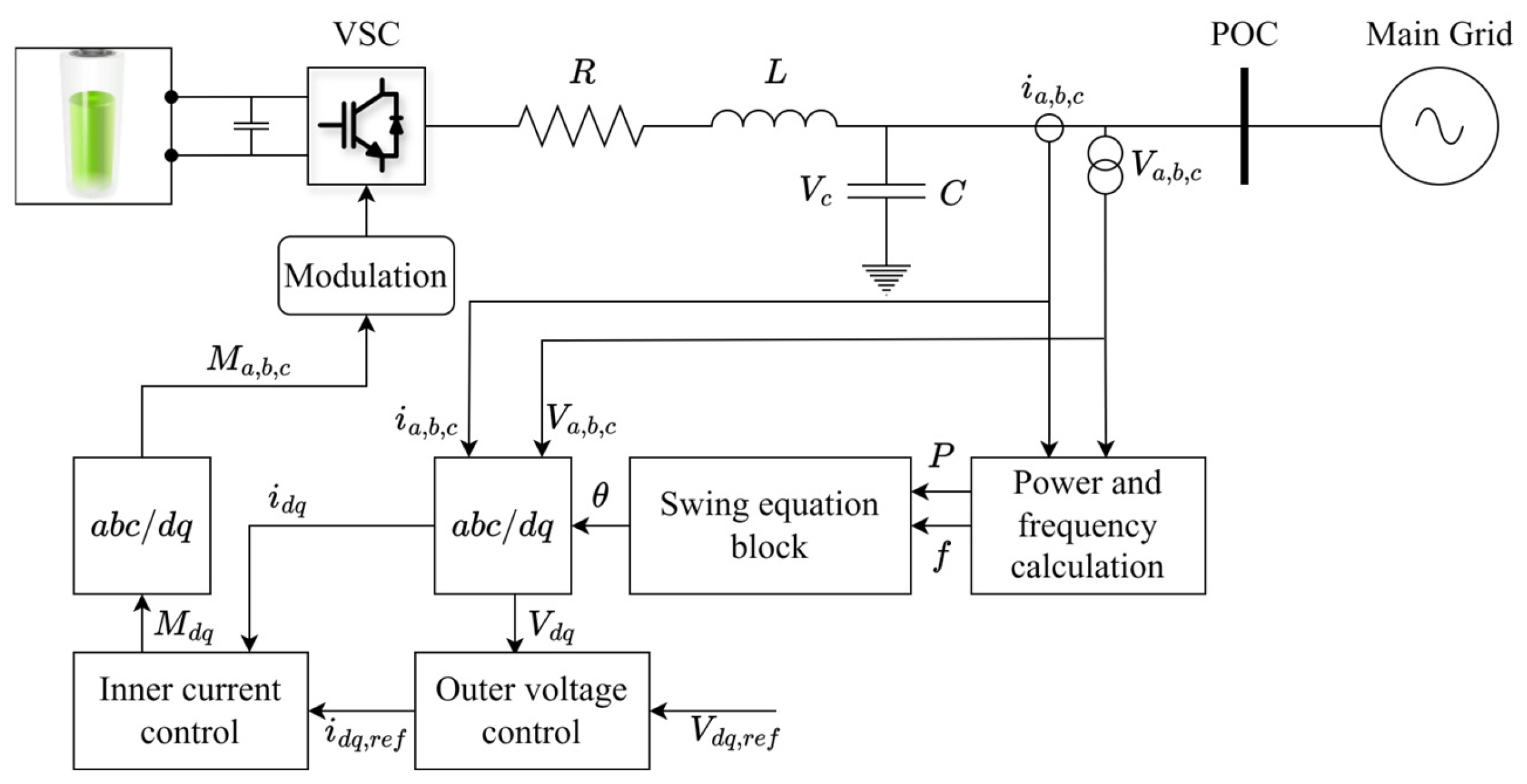
5.3. Grid-Forming Inverters

GFMIs have been established for some time in the microgrid context. Many microgrids have replaced diesel generators with GFMIs as their primary voltage reference when operating in islanded mode. However, most current GFMIs switch to GFLI mode when grid connected. The concept of GFMI operating as permanently grid-connected is relatively new and not well studied [78]. Badrzadeh at al. [79] provided a list of current grid-connected GFMI pilots implemented globally. SOs are beginning to publish requirements; however, they are still in the early stages. The National Grid Electricity SO (NG ESO, UK) published the first non-mandatory specification for GFMI in 2022 [61], followed by AEMO with a voluntary specification in 2023 [80]. TransGrid, the New South Wales transmission operator, published their test specification for voltage waveform support from GFMI in 2024 [81].
GFLIs measure grid voltage magnitude, frequency, and phase angle to control their active and reactive power outputs. Generally, GFLI’s reactive power is controlled to zero to maximise active power output and earnings in energy markets. GFMIs, on the other hand, control their output voltage magnitude, frequency, and phase angle, as shown in Figure 9. This leads to their classification as “grid-forming” [82].
The ability of GFMI algorithms to provide system strength and virtual inertia support varies widely. Numerous recent studies have focused on this topic [30,35,79,83,84,85,86,87].
Several grid-scale GFMI trials have been conducted in the NEM. The ESCRI Dalrymple battery energy storage system (BESS) was the first grid-scale BESS to implement primary frequency control. At the time of construction Dalrymple was the largest GFMI in the world, according to ElectraNet’s knowledge sharing report [88]. ElectraNet’s report demonstrated the fast frequency response capabilities of the BESS, along with the ability to island the local area using 100% RESs from the local wind farm. The BESS made contribution to the South Australian System Integrity Protection Scheme (SIPS). The report also highlighted key learnings including project delays due to complexities in the modelling of both the BESS and the local wind farm, regulatory barriers to do with asset ownership structures, and current market incentives to support such investments. Despite these challenges, the Australian Renewable Energy Agency (ARENA) has approved grants for an additional eight grid-scale GFMIs. A number of these are already operating including the Riverina BESS (150 MW) and the Hornsdale Power Reserve (150 MW). In December 2023, ARENA-approved AGL’s Liddell GFMI BESS sized at 500 MW [89].
Table 3 provides a comparison of system strength and inertia services provided by SGs, GFLIs, and GFMIs based on work presented in [90]. There is potential for wind and solar farms with appropriate control strategies to provide virtual inertia. Trials of this concept have been conducted as presented in [91]. However, the intermittent nature of RESs remains a challenge for IBRs providing reliable inertia.

5.4. Ancillary Services

To address declining grid inertia, SOs in high-IBR regions are updating or enhancing the speed of response required of frequency support ancillary services. Gilmore et al. [92] provided a comprehensive review of AEMO’s contingency frequency control ancillary services (C-FCAS). Inertia (spinning mass) alone does not restore the frequency following a contingency event, it simply slows the RoCoF down. Ancillary services with increasingly rapid responses are required to quickly restore grid frequency to the normal operating frequency band, 49.85–50.15 Hz in the NEM.
C-FCAS comprises eight markets (four raise and four lower) to restore system frequency to the normal operating band following a contingency event. In October 2023, AEMO introduced the new one-second (R1S/L1S) services to the existing suite of C-FCAS [93]. These services are also known as Very-Fast FCAS. The intent of Very-Fast FCAS is to arrest frequency decline following a contingency event, recognising that RoCoF is increasing with increasing IBR levels. R1S and L1S require a less than one-second response from service providers. For comparison, the previous fastest C-FCAS, R6S and L6S, requires a less than six second response from participants. AEMO calculates the R1S requirement every five minute interval in proportion to NEM grid inertia using (6) [94]. Based on (6), R1S demand increases as NEM inertia decreases. The legacy C-FCAS services do not use the inertia related multiplier (the first bracketed term in (6)) as the response times are not in the inertia timeframe (see Figure 2). Demand for the slower markets is based solely on the largest operating unit in the NEM less the load relief, the second bracketed term in (6). Load relief in the NEM is 0.5% of demand and represents the drop in load expected due to declining frequency [95].
R 1 S d e m a n d = 25 × M W N E M   l a r g e s t   u n i t I n e r t i a N E M                                         × M W N E M   l a r g e s t   u n i t M W l o a d   r e l i e f
The R1S market in Australia is dominated by fast-responding BESSs. NEOEN and Tesla constructed Australia’s first “big battery”. Since then, BESS construction has grown steadily, largely driven by the revenues available through providing C-FCAS services. A comprehensive list of operating BESS, detailing participation levels in both contingency and regulation FCAS, is provided on the NEMBESS website [96].
Demand response also makes a significant contribution to R1S and FCAS in general. Demand response accounts for 25% of the registered R1S capacity in the NEM. Demand response service providers (DRSPs) are aggregating large commercial and industrial plants to provide rapid C-FCAS response [97]. Demand side solutions are commendable and warrant further support and development as it does not require additional asset construction with the associated cost, time, and CO2 emissions. Table 4 provides a summary of R1S service providers in the NEM by location and capacity based on data published by AEMO as of 4 January 2025 [98].
A similar provision of rapid frequency response services via market mechanisms are seen in Ireland with the DS3 suite of services [99]. In DS3, EirGrid rewards participants with a multiplier for a fast response time down to the 150 ms level. In [99], the current frequency control approaches and virtual inertia capabilities of wind turbines are reviewed. The authors proposed that these techniques could enable up to 95% IBR penetration for the Irish grid. Kez et al. [100] demonstrated how ancillary services such as DS3 interact with spinning mass to prevent frequency deviations from the normal frequency operating band. Like Australia, demand side units (DSUs) play a significant role in the provision of DS3 services.
Ancillary service markets deal with primary frequency control; however, inertia is not currently addressed with an effective market mechanism. Several studies [92,101,102] proposed new market methods to incentivise inertia provision from non-traditional sources including virtual inertia from GFMIs. The studies highlighted that current market mechanisms are not sufficient to incentivise investment in inertia solutions. To solve the problem, ref. [101] proposed an auction-based market with investment models based on game theory. The author’s findings achieve a cost-effective high-IBR share, leveraging auction-based virtual inertia supply. Liang et al. [102] proposed a mixed-integer quadratic program (MIQP) with margin cost principals. The authors demonstrated the efficient market settlement to competitive equilibrium with their model.

6. Future Research Direction

6.1. Improve System Strength and Inertia Evaluation Methodology

6.1.1. System Strength

SCRPOC is the most widely used system strength measure for IBRs. Its formulation is provided in Table 5, along with a comparison of common SCR variations. Alternative SCR measures include the composite and weighted versions of SCR [103]. The North American Electric Reliability Corporation (NERC) published some of the earliest SCR alternative metrics in 2017 [104] based on work by CIGRE. Many of these SCR methods were analysed in [105].
In a recent study [106], IILSCR was proposed to improve on the WSCR method. The authors highlighted that the WSCR method assumes 100% interaction between IBRs at different buses, while IILSCR uses power tracing to reflect actual interactions. The IILSCR method does not consider the reactive power capability of IBRs. Li et al. [107] proposed and validated the use of deep learning to predict CSCR for IBR connections.
ESCR and the IESCR improvements were discussed in [108]. ESCR builds on the standard SCR approach by adding a term that considers reactive power from any shunt filter used at the IBR. MIESCR extends this concept further by considering multiple in-feeds. IESCR considers the MIESCR approach, with the addition of the IBR impedance as seen by the grid.
Table 5. Comparison of SCR and proposed system strength measures.
MethodFormulaContributionRef
SCRPOC S C M V A P O C M W I B R Commonly used metric. Suitable for single inverter connection at POC.[104,105]
WSCR-MW i N S C M V A i × P i ,   I B R i N M W i ,   I B R 2 Considered N IBRs in the locality and provided a weighted value.[104,105]
WSCR-MVA i N S C M V A i × P i ,   I B R i N M V A i ,   I B R 2 As per WSCR-MW but considered IBR reactive power capability.[104]
CSCR i N S C M V A i i N M W I B R Created composite bus and provides an average SCR. Assumes perfect bus coupling.[104,107]
ESCR S C M V A i , P O C Q i , f i l t e r M W i , I B R Enhanced SCR by including shunt reactive compensation.[108]
IILSCR S C M V A i , P O C M W i ,   I B R j = 1 , j i N M W i j , I B R Used power tracing to reflect bus interactions[106]
The QESCR method proposed in [109] was intended to maximise IBR penetration. It considered the reactive power that can be provided by IBRs by adding a Q I B R , j term to the SCR calculation representing the IBRs at node j’s reactive power capability, thereby increasing the effective SCR at the node. This method is shown in (7):
Q E S C R i = S C i + j = 1 , j i N N V I F j , i Δ Q j , I B R i = 1 N N V I F i , j M W i , I B R
where the NVIF term is approximately the ratio of inter-bus impedance with the bus impedance, Z j , i Z i , i . QESCR is an enhanced version of the HMESCR method proposed by the same authors in [110] to suit RES IBRs.
It is important for SOs to establish improved metrics for system strength, beyond SCRPOC, to allow for the efficient development of the grid and avoid unnecessary curtailment and constraint of IBRs. Approaches such as preventing IBR connection agreements and curtailing RES output at SCRPOC values less than 3 may not be necessary as demonstrated by [32,71,111]. The SCRPOC method does not account for IBR’s reactive power capability or GFMI contribution, and so improved measures such as QESCR are needed for a true evaluation of system strength and IBR hosting capacity.

6.1.2. Inertia

To maintain a stable grid, SOs require a real-time estimation of the grid inertia constant H. The importance of this can be referenced in Section 5.4 where an accurate inertia estimate is required to dispatch the correct amount of rapid frequency response services. H is variable in high-IBR grids, creating a need for improved on-line estimation tools. H is calculated as per (8):
H g r i d = i = 1 N 0.5 J i δ ˙ m , i 2 i = 1 N S i
where J is the i t h unit’s rotor moment of inertia, δ ˙ m , i is the i t h rotor’s angular velocity, and S i is the power rating of the   i t h unit.
An inertia estimation review [112] discussed three ongoing challenges for inertia estimation: the estimation of rotor speed and virtual frequency, the ambient and local signal perturbation for IBRs, and inertia uncertainty quantification. An inertia estimation approach was proposed in [113] based on a covariance matrix using least squares to fit the measured data to an assumed model. The authors highlighted that further work is required to improve the accuracy of their method. The method is also limited as it is dependent on the quantity and location of measurement and filtering used. The approach provided in [114] considered the asynchronous inertial contribution of loads and IBRs. The method proposed in [115] also considered asynchronous inertia. It performed well with adaptive inertia from virtual synchronous machines (VSMs) and with good noise immunity. However, limited real-world testing on the method was carried out.
The model proposed in [116] was based on phasor measurement units (PMUs) without requiring model data. The approach is limited as PMUs are not yet a standard feature on the grid and the estimation relies upon the availability of these data.
Other methods were proposed in the literature, such as perturbation-based techniques [117], preventative approaches to limit IBRs to safe frequency stability levels [118], and inferential estimates using system frequency response estimates [119]. Any approach that reduces RES levels in favour of SGs, such as [118], is to be avoided if the goal is 100% renewable energy. Constraint methods that aim to maintain minimum inertia levels while maximising RESs should be explored further. The authors of [120] demonstrated their nadir constraint approach met system requirements while increasing system costs by only 0.77% over their base case, compared with a minimum inertia-based approach, which increased costs by 12.23% while increasing thermal plant dispatch.

6.2. Improved Grid Modelling

SGs may be modelled using phasor-based approaches. They follow Newton’s laws and require minimal machine model inputs. The swing equation can be linearised around specific operating points. This approach, assuming sinusoidal steady state, allows for an analysis of systems where transients are in the electro-mechanical timeframe. Transient timeframes are illustrated in Figure 10 for reference.
IBR dynamical behaviour is software-defined [30]. IBR control algorithms are “black box” and often IP-protected by the Original Equipment Manufacturer (OEM). The dynamics occur in the Electro-Magnetic Transient (EMT) timeframe, meaning IBR dynamics cannot be accurately modelled using phasor-based techniques. EMT-based simulation is required to capture the microsecond dynamics associated with IBRs [121]. EMT simulations are computationally expensive, taking significant time to run. The Oak Ridge National Laboratory (ORNL) is running a project targeting a 100× speed improvement and 1000× scaling factor (1 million 3-phase nodes) for grid EMT simulations [122]. ORNL say this level of improvement is required for EMT to replace phasor-based simulation.
Dynamic phasor-based simulation shows promise as a hybridised approach, leveraging reduced phasor-based computational load and combining it with EMT-based fidelity [123,124,125]. The advantage of this technique is its ability to model IBR harmonics and grid interactions in the system. However, dynamic phasor modelling has limits in its ability to correctly model extreme system dynamics. Additionally, its computational complexity makes the approach unsuitable for real-time applications.
A new generic positive sequence model for IBRs was presented in [126]. This method performed well for small signal and transient analysis but uses generic current loop and PLL models; therefore, it may not capture all IBR dynamics.
Hybrid-based simulation approaches have been used since 2015, using a combination of EMT and electro-mechanical transient techniques to capture the dynamics of HVDC and FACTS devices. Ref. [127] proposed a hybrid of EMT and dynamic phasor techniques with the objective of minimising the need to model the entire network using EMT.
A review of AI-based approaches to modelling, including machine learning, was explored in [128]. The authors stated that these techniques offer similar accuracy with significant efficiency improvement when considering traditional modelling techniques.
Gomis-Bellmunt et al. [129] presented a new modelling methodology for the modern grid, considering GFMI contribution. They demonstrated the fault current error in traditional modelling methods when compared with the 0% error of their method.
These modelling improvements are required to better inform SOs. Without detailed models and scenario analysis, SOs must take a risk-based approach, which frequently results in RES curtailment. The requirement of improved grid modelling is also highlighted from the knowledge sharing report discussed in Section 5.3.
Table 6 provides a comparison of current grid modelling techniques and their characteristics.

6.3. Advanced GFLI/GFMI Control

GFLI/GFMI control methods are divided into three primary categories of droop control, virtual synchronous machine, and virtual oscillator. GFLI can provide the much-needed frequency and voltage regulation; however, VSM and dVOC capabilities are limited to GFMI inverters. In the following sub-sections, droop control will be covered briefly, while both VSM and VOC-based techniques will be explored in detail. Focus will be given to non-linear-based control techniques.
The structure for each of these control methods is provided in Figure 11 for reference. There are some notable GFMI technologies that do not fit neatly into these categories. Busada et al. [130] demonstrated a grid fault tolerant synchronverter. Their solution combined voltage source GFMI capabilities of virtual inertia and independence from a PLL with the ability to control output current to saturation while maintaining stability even with asymmetrical grid faults. The remainder of this section will focus on research that fits the three categories.

6.3.1. Droop Control

Droop control remains one of the most established control techniques for GFMIs, particularly in grid-connected applications. It is designed to replicate SG’s speed regulation [131] and is, therefore, a form of primary frequency control. Droop control is a phasor-based, linear control algorithm that effectively manages power sharing and frequency regulation in steady-state conditions, making it valuable for grid support [35].
GFMIs can provide both frequency and voltage stability support using droop control. The droop algorithms to control GFMI active and reactive power for frequency and voltage support are given as (9) and (10) [132]:
ω r e f = ω g r i d m p P m P r a t e d
V r e f = V g r i d m q Q m Q r a t e d
where w r e f and V r e f are the reference frequency and voltage, w g and V g are the corresponding measured values, and m p and m q are the active and reactive power gains.
Research continues to improve upon droop control algorithms. Numerous adaptive approaches have been proposed. An improved droop controller for wind farms was proposed in [133]. This technique leveraged fuzzy logic to dynamically adjust the droop gains based on grid conditions. Chen at al. [134] proposed an adaptive BESS droop controller that considers both grid conditions and the state-of-charge of the battery. To increase dynamic response and stability, Oraa et al. [135] proposed a single-loop droop controller for a wind turbine. This improved small signal stability, but the authors discovered instability in the approach with resonance detected in high slip and reduced phase margin at low slip. Two solutions were proposed for this: the first was a virtual resistor to damp the resonance, and the second was to introduce rotation to increase the phase margin. These solutions resolved the instabilities.
Droop control has the limitation of relying upon a PLL for synchronisation. A recent study [136] found that droop control shows a higher RoCoF and frequency overshoot. While droop control can achieve the primary frequency response shown in Figure 2, it is limited in its immediate response required to arrest the initial RoCoF.
Inverters with droop control work in conjunction with other primary frequency control measures, such as fast ancillary services and steam turbine governor control, to return and maintain grid frequency in the normal operating band.

6.3.2. Virtual Synchronous Machine

The VSM approach represents an advancement in GFMI control by dynamically linking active power to angular frequency, creating a virtual form of inertia. Ref. [137] provided a derivation and linearisation of VSM modelling together with small signal stability analysis. Wang et al. [138] demonstrated the droop and VSM response equivalence in terms of active and reactive power dynamics, meaning VSM can deliver an accurate droop-like response. In addition to droop response, VSM is designed to emulate the characteristic inertia and damping response of the swing equation. The control structure for VSM is shown in Figure 12.
The transient power angle stability for VSM was analysed in [31]. The authors highlighted that the inertia and damping constants used in the VSM control loop have a significant impact on the VSM transient stability. Li et al. [139] proposed an integral feedback control method for active power control to enhance VSM transient stability during grid faults. They used hardware in the loop (HiL) testing to demonstrate their proposed solution can maintain angle stability during a 44% voltage dip—a scenario when the base case VSM loses synchronism. Multi-VSM transient stability is analysed and improved in [140]. The authors employed a deep learning method to deal with a variety of faults. They achieved a maximum power deviation of 3.3% in all scenarios tested. The impact of VSM on grid transient and frequency stability is analysed in [141]. The authors found that the impact can be as significant as the impact from the loss of a SG. VSMs bring additional complexity as parameter changes can result in frequency stability issues. For this reason, a parameter design method was provided, focused on the damping ratio, and the authors validated their technique using RT-Lab HiL.
A key advantage of VSM over SG is its inherent ability to adjust model parameters to suit grid conditions in real time. This is especially promising for weak grids where characteristics can change quickly. Several researchers are developing adaptive-based VSM techniques [142,143,144,145,146,147,148,149,150,151,152,153,154,155,156,157,158,159,160]. Ref. [144] proposed an adaptive approach considering the converter and energy storage constraints. The proposed approach maximised inertia to reduce RoCoF and frequency nadir. The improvement to RoCoF, when compared to a fixed parameter VSM approach, was validated using the IEEE39 bus. Wang et al. [147] developed an adaptive VSM approach leveraging reinforcement learning. They demonstrated reduced oscillation following grid disturbances in weak grid conditions. Importantly, the peak amplitude of the oscillation remained within the converter limits. Study presented in [154] employed fuzzy logic in the adaptive VSM approach focused on dynamic inertia and damping parameter adjustment for enhanced system stability. Shi et al. [159] focused their adaptive VSM approach on damping frequency oscillation. The authors’ solution achieved the ability to switch between active/reactive (PQ) control in response to grid conditions. PQ mode was used for fast frequency regulation in steady state, while VSG was employed in transient conditions for enhancing frequency stability.
Much of the research in VSM focuses on inverter control. Energy storage is also a critical component required for the provision of inertia and adequate voltage support. Areed et al. [161] studied the limitation of the battery ramp rate on the provision of VSM services. The authors discovered the potential for instability due to the battery ramp rate limits in transient conditions where the inverter controller analysis may have shown stability. To address battery ramp rate issues, two studies were found in the literature. Akram et al. [162] found that the supercapacitor is an economic form for energy storage for VSMs providing fast frequency and voltage support when compared with battery energy storage. Their paper proposed a location and capacity method for VSM deployment. A flywheel based approach for VSM was proposed in [163]. The paper demonstrated that a commercial flywheel of 120 kW could emulate inertia of 47.7 kWs. This inertia contribution is comparable to a 1 MW SG.
To further enhance system transient stability in weak grids, the use of non-linear control methods such as sliding mode control (SMC) [164,165] and model-predictive control (MPC) [166,167,168,169,170,171,172] has been proposed. SMC control for VSM was developed in [164] and demonstrated improved robustness and transient response for voltage control from the VSM, while the SMC-based current loop improved load disturbance dynamics. Oshnoei and Blaabjerg [165] highlighted the transient stability issue encountered with the common (dq) synchronous reference frame and proportional integral (PI) control used in VSMs. The authors propose a hybrid MPC and SMC approach to enhance stability. SMC is used to quickly establish the weighting factors for the MPC. The work demonstrated superior total harmonic distortion (THD) reduction under disturbance conditions (4.13%) when compared to standard PI-based control (5.79%). Guo et al. [169] implemented MPC for VSM to overcome the issue of varying component values (filter components such as inductors and capacitors) during temperature and current fluctuations. Using HiL-based experiments, the authors validated the superior robustness of their method during grid disturbances with varying component parameter values. MPC was also demonstrated in [172] to enhance VSM control methods by addressing the overcurrent protection and fault ride through issues. Fuzzy approaches are demonstrated in [173,174]. Ref. [173] proposed a fuzzy-based solution to mitigate the frequency deviations that may occur as a VSM synchronises to the grid when considering islanded operation mode.
Communication is a significant issue for VSM in the modern smart grids. The method proposed in [167] explored the issues of restricted or no communication for their MPC-based controller. Methods such as MPC rely upon communication for accurate state estimation. This proposal avoided the issue by integrating an observer into their system. The issue of cyber security was explored in [175]. To avoid the costs, cyber security threats, and delays involved in communications for GFMI, Ref. [34] proposed a communication free implementation for GFMI. The computational complexity issue of advanced VSM control is addressed in [176]. The authors’ polymorphic VSM control is optimised considering the limited computational power of commercial inverters. The study provided an analysis of the trade-off in VSM performance and computational burden.
Based on the above discussion, VSM areas call for more detailed research including the following:
  • The energy storage ramp rate impact on VSM stability requires further study. Research is required before the integration and impact of energy storage for VSM systems is clear.
  • The transient stability issue remains for VSM. This is due to the use of linear control techniques, such as PI, in many current implementations. Issues such as energy storage ramping and filter parameter changes have also been shown to impact stability. Non-linear techniques, SMC and MPC, have demonstrated increased stability margin and robustness for VSM, but research and real-world implementation remain limited.
  • Smart-grid technologies like VSM involve the use of communications and can be computationally expensive. As VSMs are a critical power grid infrastructure, further research is required in this area to ensure that new solutions are secure, cost-effective, and implementable on existing inverter technology.

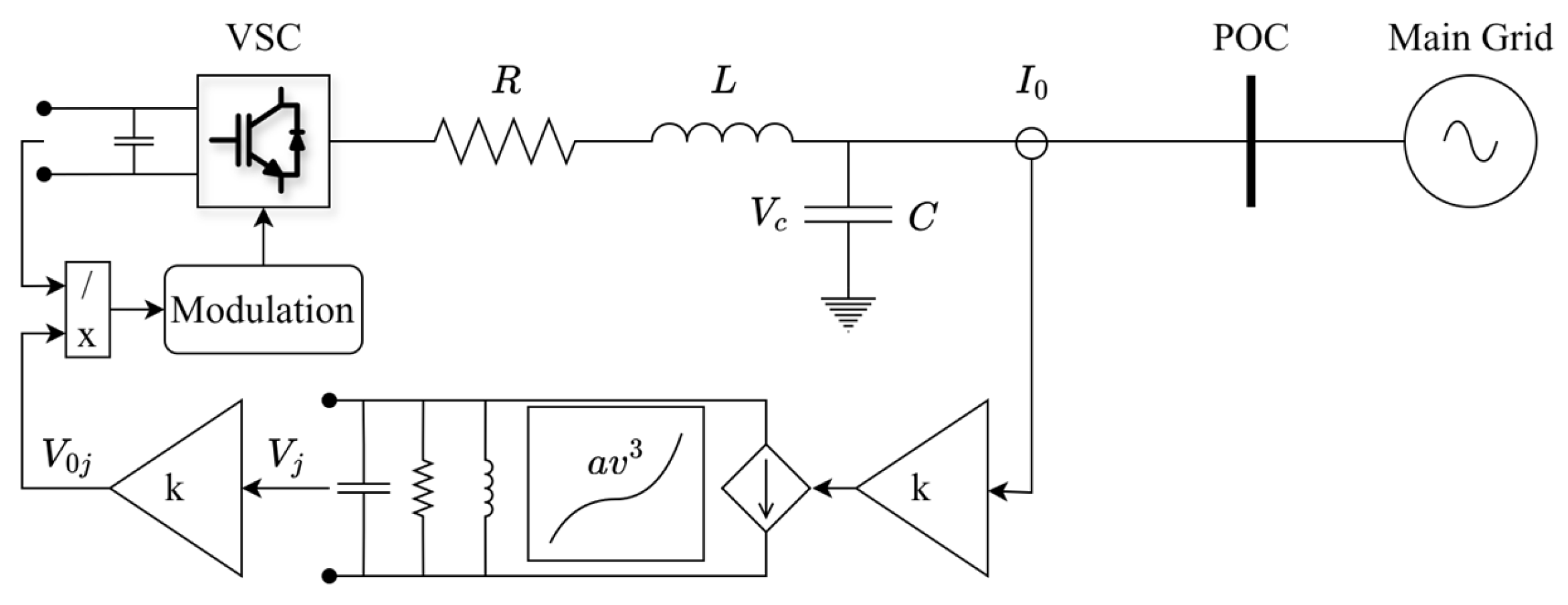
6.3.3. Dispatchable Virtual Oscillator Control

The general structure for dVOC is shown in Figure 13 where the current measurement is fed back via a gain block to the oscillator, and the output is fed via another gain block to the modulation block for the VSC. dVOC is a non-linear, time-domain-based control algorithm and does not rely upon PLL for synchronisation. dVOC was shown to outperform droop control for dynamic response in [177].
Quedan et al. [152] demonstrated the fast response and recovery from transient conditions they achieved using the Andronov–Hopf oscillator (AHO) VOC approach. A solution for the third-order harmonic issue associated with VOCs is addressed in [178]. Awal et al. [179] addressed the asymmetrical fault issue of standard Voltage Source Converters (VSCs) by achieving negative sequence synchronisation along with the positive sequence in their dVOC implementation. Nui et al. [180] combined VOC with SMC-based control. The improved voltage tracking during synchronisation is demonstrated using RT-LAB HIL-based experiments. Further VOC-based solutions were demonstrated in [181,182]. Detailed unified sequence impedance models for VOC and VSM were developed in [183]. This work helped to capture the voltage characteristics and characterise the synchronisation of both methods.
The time-based control introduces difficulties for dVOCs in providing system strength services. To overcome this limitation, a virtual impedance-based approach was proposed in [85]. This is a promising step; however, dVOC research appears to be lagging the VSM approach in the literature.

6.3.4. GFMI Fault Current

All three GFMI control solutions still have the fault current limits of PE, and post-fault event recovery issues [87]. GFMI control algorithms generally switch to GFLI or current saturation mode during faults to protect the PE from overcurrent damage [184]. These approaches limit the provision of system strength and inertia services at a critical time. Therefore, GFMI control algorithms require further research and development.

6.3.5. Swing Equation Derivation from Energy

It is instructive for power system engineers to consider the swing equation from the perspective of energy rather than from the traditional forces approach using Newton’s equation. This is relevant for non-linear control and modelling and supports advanced stability analyses. This is also a critical area for achieving resilient and adaptive IBR power systems. Therefore, the swing equation will be driven here using Lagrangian mechanics to highlight energy transfer within the system.
The kinetic energy (KE) of the SG of a rotor moment of inertia J is given by (11):
K E = 0.5 J δ ˙ m 2
The potential energy for a 2-pole SG is given by (12):
P E = P e , m a x s i n δ m d δ m
Integrating (12) gives (13) representing the potential energy of the SG:
P e , m a x c o s δ m
The Lagrangian of the system, representing the difference between the kinetic and potential energy, is formulated as (14):
L = 0.5 J δ ˙ m 2 P e , m a x c o s δ m
The modified Euler–Lagrange equation with forcing terms P m and D δ ˙ m (15) is then applied to (14):
d d t L δ ˙ m L δ m = P m D δ ˙ m
yielding the conventional swing Equation (16):
J ω m s δ ¨ + D δ ˙ + P e , m a x s i n δ m = P m
where ω m s is the mechanical synchronous speed, and δ m is the rotor angle, calculated from δ m = θ m ω m s t , where θ m is the absolute mechanical angular position.

7. Discussion

This review covers a broad range of recent research in the categories of system strength and inertia evaluation methods, grid modelling, and advanced GFMI control. A summary of the recent literature—since 2021—reviewed in this work, together with the contributions and limitations is provided in Table 7.
Novel and less-studied approaches from this review are presented as a framework in Table 8. This work represents the author’s insights to inform policy makers and SOs of new and emerging mitigation solutions for declining system strength and inertia that may not be otherwise under consideration.

Benefit to Planetary Health

Transitioning to beyond 100% RESs is a critical strategy to mitigate climate change, safeguard ecosystems, and promote global well-being [185]. Ensuring adequate system strength and inertia in high-IBR grids not only secures reliable power supply but also underpins essential infrastructure—from critical healthcare to water treatment—that collectively contributes to societal resilience and human health [186]. By reducing dependence on carbon-intensive generation, robust RESs help to lower pollution and resource depletion, supporting both ecological stability and public health outcomes. This aligns with key United Nations Sustainable Development Goals (e.g., SDG 7: Affordable and Clean Energy; SDG 13: Climate Action) [187], which highlights the broader socio-economic and environmental benefits of a cleaner, more resilient energy future.
Demand response is seen as a key component of the social and cultural aspects given that the concept promotes public involvement and monetary benefits from playing a supporting role in providing the stability services described in this review. This level of involvement promotes public awareness and much needed support to achieve the necessary goals during the energy transition. Increased awareness of demand response’s role can also help to control the costs and economic impacts of the energy transition.

8. Conclusions

As energy markets shift towards high levels of RES integration, the reduction in system strength and inertia poses significant challenges to grid stability. This paper has outlined the critical issues and current solutions, examining the roles of SynCons, FACTS, and GFMIs in mitigating these issues. The paper shows that SOs in the electricity markets of Australia, Ireland, and Texas are forced to curtail significant amounts of RESs to maintain power system security. System strength evaluation methods result in more RES curtailment and project delays than is necessary. To address this, our review shows that improved system strength measures are required along with real-time inertia estimation methods, highlighting the urgency of developing new tools for grid operators. Emerging technologies, including hybrid grid modelling techniques and advanced GFMI controls, require further research and development to reliably support high-IBR grids on a large scale. The paper has provided a detailed analysis of the recent literature on VSM and VOC techniques to address the declining inertia and system strength issue. The potential of VSM to enhance grid stability has been assessed, along with its limitations and areas for future research. Moreover, the paper provides actionable insights and a recommendation framework to reduce operator interventions and avoid unnecessary RES curtailment, paving the way for a sustainable 100% IBR grid while facilitating improved planetary health outcomes.

Author Contributions

Conceptualization, P.M.; methodology, P.M.; investigation, P.M., O.A.A. and A.A.-S.; resources, O.A.A.; writing—original draft preparation, P.M.; writing—review and editing, A.A.-S. and O.A.A.; visualization and supervision, O.A.A. and A.A.-S. All authors have read and agreed to the published version of the manuscript.

Funding

This research received no external funding.

Data Availability Statement

Not Applicable.

Conflicts of Interest

The authors declare no conflicts of interest.

References

  1. United Nations Climate Change The Paris Agreement | UNFCCC. Available online: https://unfccc.int/process-and-meetings/the-paris-agreement (accessed on 13 September 2024).
  2. Graham, P.; Hayward, J.; Foster, J. GenCost 2023-24: Final Report; CSIRO: Canberra, ACT, Australia, 2023. [Google Scholar]
  3. CEC Quarterly Carbon Market Report December Quarter 2023. Available online: https://cer.gov.au/markets/reports-and-data/quarterly-carbon-market-reports/quarterly-carbon-market-report-december-quarter-2023/state-of-total-renewables (accessed on 13 September 2024).
  4. Vorwerk, J.; Dozein, M.G.; Mancarella, P.; Hug, G. Analytical Discussion on Dynamics of Inverter-Based Resources under Small-Signal Conditions. In Proceedings of the 2023 IEEE Belgrade PowerTech, Belgrade, Serbia, 25–29 June 2023; pp. 1–6. [Google Scholar]
  5. Gu, H.; Yan, R.; Saha, T.K.; Muljadi, E. System Strength and Inertia Constrained Optimal Generator Dispatch Under High Renewable Penetration. IEEE Trans. Sustain. Energy 2020, 11, 2392–2406. [Google Scholar] [CrossRef]
  6. Aljarrah, R.; Fawaz, B.B.; Salem, Q.; Karimi, M.; Marzooghi, H.; Azizipanah-Abarghooee, R. Issues and Challenges of Grid-Following Converters Interfacing Renewable Energy Sources in Low Inertia Systems: A Review. IEEE Access 2024, 12, 5534–5561. [Google Scholar] [CrossRef]
  7. Gu, H.; Yan, R.; Saha, T.K. Review of System Strength and Inertia Requirements for the National Electricity Market of Australia. CSEE J. Power Energy Syst. 2019, 5, 295–305. [Google Scholar] [CrossRef]
  8. Peng, Q.; Jiang, Q.; Yang, Y.; Liu, T.; Wang, H.; Blaabjerg, F. On the Stability of Power Electronics-Dominated Systems: Challenges and Potential Solutions. IEEE Trans. Ind. Appl. 2019, 55, 7657–7670. [Google Scholar] [CrossRef]
  9. Qays, M.O.; Ahmad, I.; Habibi, D.; Aziz, A.; Mahmoud, T. System Strength Shortfall Challenges for Renewable Energy-Based Power Systems: A Review. Renew. Sustain. Energy Rev. 2023, 183, 113447. [Google Scholar] [CrossRef]
  10. Boričić, A.; Torres, J.L.R.; Popov, M. System Strength: Classification, Evaluation Methods, and Emerging Challenges in IBR-Dominated Grids. In Proceedings of the 2022 IEEE PES Innovative Smart Grid Technologies—Asia (ISGT Asia), Singapore, 1–5 November 2022; pp. 185–189. [Google Scholar]
  11. Ghazavi, M.; Mancarella, P.; Saha, T.; Yan, R. System Strength and Weak Grids: Fundamentals, Challenges, and Mitigation Strategies. In Proceedings of the 2018 Australasian Universities Power Engineering Conference (AUPEC), Auckland, New Zealand, 27–30 November 2018; pp. 1–7. [Google Scholar]
  12. AEMO. System Strength in the NEM Explained; Australian Energy Market Operator: Melbourne, VIC, Australia, 2020. [Google Scholar]
  13. Hosseinzadeh, N.; Liyanarachchi, L.; Gargoom, A.; Alhelou, H.H.; Bahrani, B.; Fahiman, F.; Farahani, E. Power System Strength Assessment with High Penetration of Inverter-Based Resources—A Conceptual Approach. In Power System Strength Evaluation Methods, Best Practise, Case Studies, and Applications; Institution of Engineering and Technology: Stevenage, UK, 2023. [Google Scholar]
  14. Fang, J.; Li, H.; Tang, Y.; Blaabjerg, F. On the Inertia of Future More-Electronics Power Systems. IEEE J. Emerg. Sel. Top. Power Electron. 2019, 7, 2130–2146. [Google Scholar] [CrossRef]
  15. Alkhazim, H.A.; Bajunaid, S.I.; Alsulami, W.A.; Alghamdi, M.S. Impact of Inverter Based Resources on Power System Protective Relaying, Fault Calculation and Protection Setting: A Systematic Literature Review. In Proceedings of the 2022 Saudi Arabia Smart Grid (SASG), Riyadh, Saudi Arabia, 12–14 December 2022; pp. 1–11. [Google Scholar]
  16. Matevosyan, J.; MacDowell, J.; Miller, N.; Badrzadeh, B.; Ramasubramanian, D.; Isaacs, A.; Quint, R.; Quitmann, E.; Pfeiffer, R.; Urdal, H.; et al. A Future With Inverter-Based Resources: Finding Strength From Traditional Weakness. IEEE Power Energy Mag. 2021, 19, 18–28. [Google Scholar] [CrossRef]
  17. Ghosh, S.; Alhatlani, A.; Safayatullah, M.; Batarseh, I. Review of MPPT Methods for LLC Converters in Photovoltaic Applications. In Proceedings of the 2022 IEEE Energy Conversion Congress and Exposition (ECCE), Detroit, MI, USA, 9–13 October 2022; pp. 1–6. [Google Scholar]
  18. Alharbi, M. Control Approach of Grid-Connected PV Inverter under Unbalanced Grid Conditions. Processes 2024, 12, 212. [Google Scholar] [CrossRef]
  19. Yu, L.; Meng, K.; Zhang, W.; Zhang, Y. An Overview of System Strength Challenges in Australia’s National Electricity Market Grid. Electronics 2022, 11, 224. [Google Scholar] [CrossRef]
  20. Modi, N.; Farahani, E.M.; Jalali, A.; Ramamurthy, J.; Chin, C.; Soetantijo, B. Replication of Real-World Sub-Synchronous Oscillations in Inverter-Based Resources Dominated Grid. IEEE Trans. Power Deliv. 2024, 39, 1399–1406. [Google Scholar] [CrossRef]
  21. Alshareef, A.; Shah, R.; Mithulananthan, N.; Alzahrani, S. A New Global Index for Short Term Voltage Stability Assessment. IEEE Access 2021, 9, 36114–36124. [Google Scholar] [CrossRef]
  22. Feng, F.; Fang, J. Weak Grid-Induced Stability Problems and Solutions of Distributed Static Compensators with Voltage Droop Support. Electronics 2022, 11, 1385. [Google Scholar] [CrossRef]
  23. Zhang, Q.; Mao, M.; Ke, G.; Zhou, L.; Xie, B. Stability Problems of PV Inverter in Weak Grid: A Review. IET Power Electron. 2020, 13, 2165–2174. [Google Scholar] [CrossRef]
  24. Saleem, M.I.; Saha, S.; Ang, L.; Izhar, U.; Roy, T.K. Factors Affecting Voltage Stability While Integrating Inverter Based Renewable Energy Sources into Weak Power Grids. IET Gener. Transm. Distrib. 2023, 17, 1216–1231. [Google Scholar] [CrossRef]
  25. Yan, N.; Shi, L. Transient Voltage Stability Assessment Incorporating Uncertainties of Wind-PV Generation and Load. In Proceedings of the 12th International Conference on Renewable Power Generation (RPG 2023), Shanghai, China, 14–15 October 2023; The Institution of Engineering and Technology: Stevenage, UK, 2023; Volume 2023, pp. 773–778. [Google Scholar]
  26. Li, M.; Zhang, X.; Fu, X.; Geng, H.; Zhao, W. Stability Studies on PV Grid-Connected Inverters under Weak Grid: A Review. Chin. J. Electr. Eng. 2024, 10, 1–19. [Google Scholar] [CrossRef]
  27. Yallamilli, R.S.; Dwibhashyam, T.; Bavisetti, K. Weak Grid Integrated PV Plant Design Considerations for Improved Voltage Stability. In Proceedings of the 2022 22nd National Power Systems Conference (NPSC), New Delhi, India, 17–19 December 2022; pp. 59–64. [Google Scholar]
  28. Hu, B.; Cao, W.; Yang, M.; Lu, Y. The Optimal Ratio of GFM-Converters to GFL-Converters for Transient Voltage Regulation with Weak Grid Condition. In Proceedings of the 2023 IEEE 7th Conference on Energy Internet and Energy System Integration (EI2), Hangzhou, China, 15–18 December 2023; pp. 1993–1998. [Google Scholar]
  29. Alanazi, M.; Salem, M.; Sabzalian, M.H.; Prabaharan, N.; Ueda, S.; Senjyu, T. Designing a New Controller in the Operation of the Hybrid PV-BESS System to Improve the Transient Stability. IEEE Access 2023, 11, 97625–97640. [Google Scholar] [CrossRef]
  30. Ravanji, M.H.; Zhou, W.; Mohammed, N.; Bahrani, B. Comparative Analysis of the Power Output Capabilities of Grid-Following and Grid-Forming Inverters Considering Static, Dynamic, and Thermal Limitations. IEEE Trans. Power Syst. 2024, 39, 2693–2705. [Google Scholar] [CrossRef]
  31. Cheng, X.K.; Liu, H.; Song, P.; Sun, D.W.; Zhang, R.F. Review on Transient Power Angle Stability of System with Doubly-Fed Induction Generator Based on Virtual Synchronous Generator. In Proceedings of the 2020 IEEE 4th Conference on Energy Internet and Energy System Integration (EI2), Wuhan, China, 30 October–1 November 2020; pp. 1614–1619. [Google Scholar]
  32. Yu, L.; Sun, H.; Xu, S.; Zhao, B.; Zhang, J. A Critical System Strength Evaluation of a Power System with High Penetration of Renewable Energy Generations. CSEE J. Power Energy Syst. 2022, 8, 710–720. [Google Scholar] [CrossRef]
  33. Dong, X.; Kang, C.; Ding, Y.; Wang, C. Estimating the Wind Power Integration Threshold Considering Electro-Thermal Coupling of Overhead Transmission Lines. IEEE Trans. Power Syst. 2019, 34, 3349–3358. [Google Scholar] [CrossRef]
  34. He, L.; Yu, S. Systematic Decoupling Grid-Forming Control for Utility-Scale Inverter-Based Distributed Energy Resources in Weak Distribution Grids. IEEE Open Access J. Power Energy 2024, 11, 27–39. [Google Scholar] [CrossRef]
  35. Mohammed, N.; Udawatte, H.; Zhou, W.; Hill, D.J.; Bahrani, B. Grid-Forming Inverters: A Comparative Study of Different Control Strategies in Frequency and Time Domains. IEEE Open J. Ind. Electron. Soc. 2024, 5, 185–214. [Google Scholar] [CrossRef]
  36. Kundur, P. Classification of Stability. In Power System Stability and Control; Power Engineering Series; McGraw Hill: New York, NY, USA, 1994. [Google Scholar]
  37. Hatziargyriou, N.; Milanovic, J.; Rahmann, C.; Ajjarapu, V.; Canizares, C.; Erlich, I.; Hill, D.; Hiskens, I.; Kamwa, I.; Pal, B.; et al. Definition and Classification of Power System Stability—Revisited & Extended. IEEE Trans. Power Syst. 2021, 36, 3271–3281. [Google Scholar] [CrossRef]
  38. Sainz, L.; Cheah-Mane, M.; Monjo, L.; Liang, J.; Gomis-Bellmunt, O. Positive-Net-Damping Stability Criterion in Grid-Connected VSC Systems. IEEE J. Emerg. Sel. Top. Power Electron. 2017, 5, 1499–1512. [Google Scholar] [CrossRef]
  39. Surinkaew, T.; Emami, K.; Shah, R.; Islam, S.; Mithulananthan, N. Forced Oscillation in Power Systems With Converter Controlled-Based Resources–A Survey With Case Studies. IEEE Access 2021, 9, 150911–150924. [Google Scholar] [CrossRef]
  40. Damas, R.N.; Son, Y.; Yoon, M.; Kim, S.-Y.; Choi, S. Subsynchronous Oscillation and Advanced Analysis: A Review. IEEE Access 2020, 8, 224020–224032. [Google Scholar] [CrossRef]
  41. Liao, Y.; Wang, X.; Liu, F.; Xin, K.; Liu, Y. Sub-Synchronous Control Interaction in Grid-Forming VSCs with Droop Control. In Proceedings of the 2019 4th IEEE Workshop on the Electronic Grid (eGRID), Xiamen, China, 11–14 November 2019; pp. 1–6. [Google Scholar]
  42. Zhao, F.; Wang, X.; Zhou, Z.; Sun, Y.; Harnefors, L.; Zhu, T. Robust Grid-Forming Control With Active Susceptance. IEEE Trans. Power Electron. 2023, 38, 2872–2877. [Google Scholar] [CrossRef]
  43. AEMO. 2024 ISP Chart Data; Australian Energy Market Operator: Melbourne, VIC, Australia, 2024. [Google Scholar]
  44. OpenNEM. Open Electricity: South Australia; The SuperPower Institute: Fitzroy, VIC, Australia, 2024. [Google Scholar]
  45. Chaudhuri, B.; Ramasubramanian, D.; Matevosyan, J.; O’Malley, M.; Miller, N.; Green, T.; Zhou, X. Rebalancing Needs and Services for Future Grids: System Needs and Service Provisions With Increasing Shares of Inverter-Based Resources. IEEE Power Energy Mag. 2024, 22, 30–41. [Google Scholar] [CrossRef]
  46. U.S. Energy Information Administration. Table 9. Electricity Generating Capacity. 2024. Available online: https://www.eia.gov/outlooks/aeo/data/browser/#/?id=9-AEO2023&cases=ref2023&sourcekey=0 (accessed on 7 November 2024).
  47. EirGrid. System and Renewable Data Reports; EirGrid: Dublin, Ireland, 2024. [Google Scholar]
  48. AEMO. 2023 Inertia Report; Australian Energy Market Operator: Melbourne, VIC, Australia, 2023. [Google Scholar]
  49. Harper, K. FCAS Model in NEMDE; Australian Energy Market Operator: Melbourne, VIC, Australia, 2024. [Google Scholar]
  50. AEMO. Market Notices. Available online: https://aemo.com.au/market-notices (accessed on 4 November 2024).
  51. AEMO. 2023 System Strength Report; Australian Energy Market Operator: Melbourne, VIC, Australia, 2023. [Google Scholar]
  52. EirGrid; SONI System Strength Requirements Secure Operation of the All-Island Power System in the Presence of High Shares of Inverter Based Resources; EirGrid: Dublin, Ireland, 2024.
  53. EirGrid; SONI DS3 Rate of Change of Frequency Modification Recommendation to the CER; EirGrid: Dublin, Ireland, 2012.
  54. EirGrid; SONI Annual Renewable Energy Constraint and Curtailment Report 2023; EirGrid SONI: Dublin, Ireland, 2024.
  55. Matevosyan, J. Benefits of Grid-Forming Energy Storage Resources: A Unique Window of Opportunity in ERCOT. ESIG (Energy Systems Integration Group): Reston, VA, USA, 2022. [Google Scholar]
  56. Lee, D. Keeping Up with the Curtailment Part 2: The What and the Where; WattClarity: Brisbane, QLD, Australia, 2024. [Google Scholar]
  57. IMM. 2023 State of the Market Report for the ERCOT Electricity Markets; Independent Market Monitor (Potomac Economics): Fairfax, VA, USA, 2024. [Google Scholar]
  58. AEMO. West Murray Zone Intermittent Power System Oscillations—Sample 19 Hz Oscillations Data; Australian Energy Market Operator: Melbourne, VIC, Australia, 2021. [Google Scholar]
  59. Khan, M.; Wu, W.; Li, L. Grid-Forming Control for Inverter-Based Resources in Power Systems: A Review on Its Operation, System Stability, and Prospective. IET Renew. Power Gener. 2024, 18, 887–907. [Google Scholar] [CrossRef]
  60. Cheng, Y.; Fan, L.; Rose, J.; Huang, S.-H.; Schmall, J.; Wang, X.; Xie, X.; Shair, J.; Ramamurthy, J.R.; Modi, N.; et al. Real-World Subsynchronous Oscillation Events in Power Grids With High Penetrations of Inverter-Based Resources. IEEE Trans. Power Syst. 2023, 38, 316–330. [Google Scholar] [CrossRef]
  61. Modi, N.; Escudero, M.V.; Aramaki, K.; Zhou, X.; Partinen, P. High Inverter-Based Resource Integration: The Experience of Five System Operators. IEEE Power Energy Mag. 2024, 22, 78–88. [Google Scholar] [CrossRef]
  62. Parkinson, G. Flicker Fest: Production Halted at Australia’s Biggest Wind and Solar Farm After Voltage Issues. Available online: https://reneweconomy.com.au/flicker-fest-production-halted-at-australias-biggest-wind-and-solar-farm-after-voltage-issues/ (accessed on 31 December 2024).
  63. NERC. 2022 Odessa Disturbance; North American Electric Reliability Corporation: Atlanta, Georgia, 2022. [Google Scholar]
  64. NERC. Odessa Disturbance 2021; North American Electric Reliability Corporation: Atlanta, Georgia, 2021. [Google Scholar]
  65. Fan, L.; Wang, Z.; Miao, Z. Large Angle Deviation in Grid-Following IBRs Upon Grid Voltage Dip. IEEE Trans. Energy Convers. 2024, 39, 368–378. [Google Scholar] [CrossRef]
  66. Hadavi, S.; Mansour, M.Z.; Bahrani, B. Optimal Allocation and Sizing of Synchronous Condensers in Weak Grids With Increased Penetration of Wind and Solar Farms. IEEE J. Emerg. Sel. Top. Circuits Syst. 2021, 11, 199–209. [Google Scholar] [CrossRef]
  67. Hadavi, S.; Saunderson, J.; Mehrizi-Sani, A.; Bahrani, B. A Planning Method for Synchronous Condensers in Weak Grids Using Semi-Definite Optimization. IEEE Trans. Power Syst. 2023, 38, 1632–1641. [Google Scholar] [CrossRef]
  68. Zhang, Y.; Gole, A.M. Quantifying the Contribution of Dynamic Reactive Power Compensators on System Strength at LCC-HVdc Converter Terminals. IEEE Trans. Power Deliv. 2022, 37, 449–457. [Google Scholar] [CrossRef]
  69. Hadavi, S.; Rathnayake, D.B.; Jayasinghe, G.; Mehrizi-Sani, A.; Bahrani, B. A Robust Exciter Controller Design for Synchronous Condensers in Weak Grids. IEEE Trans. Power Syst. 2022, 37, 1857–1867. [Google Scholar] [CrossRef]
  70. Hadavi, S.; Mohammed, N.; Mehrizi-Sani, A.; Bahrani, B. Quantifying Stability in Inverter-Based Weak Grids in the Presence of Synchronous Condensers. IEEE Open Access J. Power Energy 2024, 11, 314–324. [Google Scholar] [CrossRef]
  71. Yamada, Y.; Tsusaka, A.; Nanahara, T.; Yukita, K. A Study on Short-Circuit-Ratio for an Inverter-Based Resource With Power-Voltage Curves. IEEE Trans. Power Syst. 2024, 39, 6076–6086. [Google Scholar] [CrossRef]
  72. Siemens. Supporting Grid Stability—Building a New Energy System with Synchronous Condenser Conversion; Siemens Energy Global GmbH: Erlangen, Germany, 2024; Available online: https://www.siemens-energy.com/global/en/home/publications/technical-paper/download-grid-stability-synchronous-condenser-conversion.html (accessed on 23 October 2024).
  73. ElectraNet Power System Strength (Synchronous Condensers). Available online: https://www.electranet.com.au/what-we-do/projects/power-system-strength/ (accessed on 16 March 2024).
  74. Conn, J.; Huang, S.H.; Schmall, J.; Atallah, A.; Kynev, S. Synchronous Condenser for Integration of Wind Generation in Texas Panhandle Area; CIGRE US National Committee 2019 Grid of the Future Symposium; CIGRE: Paris, France, 2019. [Google Scholar]
  75. Sharma, S.; Gupta, S.; Zuhaib, M.; Bhuria, V.; Malik, H.; Almutairi, A.; Afthanorhan, A.; Hossaini, M.A. A Comprehensive Review on STATCOM: Paradigm of Modeling, Control, Stability, Optimal Location, Integration, Application, and Installation. IEEE Access 2024, 12, 2701–2729. [Google Scholar] [CrossRef]
  76. Arabi, S.; Kundur, P. Stability Modelling of Storage Devices in FACTS Applications. In Proceedings of the 2001 Power Engineering Society Summer Meeting. Conference Proceedings (Cat. No.01CH37262), Vancouver, BC, Canada, 15–19 July 2001; Volume 2, pp. 767–771. [Google Scholar]
  77. Su, J.; Chen, C. Dynamic Modeling and Stability Analysis of the Composite Power System with Power Electronic Equipments. In Proceedings of the Proceedings. International Conference on Power System Technology, Kunming, China, 13–17 October 2002; Volume 3, pp. 1488–1492. [Google Scholar]
  78. Rathnayake, D.B.; Akrami, M.; Phurailatpam, C.; Me, S.P.; Hadavi, S.; Jayasinghe, G.; Zabihi, S.; Bahrani, B. Grid Forming Inverter Modeling, Control, and Applications. IEEE Access 2021, 9, 114781–114807. [Google Scholar] [CrossRef]
  79. Badrzadeh, B.; Cardozo, C.; Hishida, M.; Shah, S.; Huq, I.; Modi, N.; Morton, A. Grid-Forming Inverters: Project Demonstrations and Pilots. IEEE Power Energy Mag. 2024, 22, 66–77. [Google Scholar] [CrossRef]
  80. AEMO. Voluntary Specification for Grid-Forming Inverters; Australian Energy Market Operator: Melbourne, VIC, Australia, 2023. [Google Scholar]
  81. Transgrid. Stable Voltage Waveform Support Specifications for Grid-Forming BESS; Meeting System Strength Requirements in NSW’ Project Assessment Draft Report (PADR); Tansgrid: Sydney, NSW, Australia, 2024. [Google Scholar]
  82. Hoke, A.; Boemer, J.C.; Badrzadeh, B.; MacDowell, J.; Kurthakoti, D.; Marszalkowski, B.; Meuser, M. Foundations for the Future Power System: Inverter-Based Resource Interconnection Standards. IEEE Power Energy Mag. 2024, 22, 42–54. [Google Scholar] [CrossRef]
  83. Liyanage, C.; Nutkani, I.; Meegahapola, L. A Comparative Analysis of Prominent Virtual Synchronous Generator Strategies Under Different Network Conditions. IEEE Open Access J. Power Energy 2024, 11, 178–195. [Google Scholar] [CrossRef]
  84. Jiang, S.; Zhu, Y.; Xu, T.; Konstantinou, G. Current-Synchronization Control of Grid-Forming Converters for Fault Current Limiting and Enhanced Synchronization Stability. IEEE Trans. Power Electron. 2024, 39, 5271–5285. [Google Scholar] [CrossRef]
  85. Ghosh, R.; Tummuru, N.R.; Rajpurohit, B.S. Dynamic Voltage Stiffness Control Technique for a Virtual Oscillator-Based Grid- Forming Controller. IEEE Trans. Ind. Electron. 2024, 71, 5725–5733. [Google Scholar] [CrossRef]
  86. Ducoin, E.A.S.; Gu, Y.; Chaudhuri, B.; Green, T.C. Analytical Design of Contributions of Grid-Forming and Grid-Following Inverters to Frequency Stability. IEEE Trans. Power Syst. 2024, 39, 6345–6358. [Google Scholar] [CrossRef]
  87. Bahrani, B.; Ravanji, M.H.; Kroposki, B.; Ramasubramanian, D.; Guillaud, X.; Prevost, T.; Cutululis, N.-A. Grid-Forming Inverter-Based Resource Research Landscape: Understanding the Key Assets for Renewable-Rich Power Systems. IEEE Power Energy Mag. 2024, 22, 18–29. [Google Scholar] [CrossRef]
  88. ElectraNet. ESCRI-SA Battery Energy Storage Final Knowledge Sharing Report; ElectraNet: Adelaide, SA, Australia, 2021. [Google Scholar]
  89. ARENA. Green Light for Australia’s Largest Grid-Forming Battery. Available online: https://arena.gov.au/news/green-light-for-australias-largest-grid-forming-battery/ (accessed on 5 January 2025).
  90. Phurailatpam, C.; Flynn, D. Requirements and Grid Standards for Grid-Forming Inverters. In Grid-Forming Power Inverters Control and Applications; CRC Press: Boca Raton, FL, USA, 2023. [Google Scholar]
  91. AEMO. Hornsdale Wind Farm 2 FCAS Trial; Australian Energy Market Operator: Melbourne, VIC, Australia, 2018. [Google Scholar]
  92. Gilmore, J.; Nolan, T.; Simshauser, P. The Levelised Cost of Frequency Control Ancillary Services in Australia’s National Electricity Market. Energy J. 2022, 45, 201–229. [Google Scholar] [CrossRef]
  93. Corbet, L. Very Fast Raise and Lower FCAS Markets to Start on 9 October 2023; WattClarity: Brisbane, QLD, Australia, 2023. [Google Scholar]
  94. AEMO. Market Ancillary Service Specification 8.2; Australian Energy Market Operator: Melbourne, VIC, Australia, 2024. [Google Scholar]
  95. AEMO. Review of NEM Load Relief; Australian Energy Market Operator: Melbourne, VIC, Australia, 2023. [Google Scholar]
  96. NEMBESS. Available online: https://nembess.com (accessed on 2 January 2025).
  97. Corbet, L. Very Fast FCAS—A Week in Review; WattClarity: Brisbane, QLD, Australia, 2023. [Google Scholar]
  98. AEMO. NEM Registration and Exemption List; Australian Energy Market Operator: Melbourne, VIC, Australia, 2025. [Google Scholar]
  99. Boyle, J.; Littler, T. A Review of Frequency-Control Techniques for Wind Power Stations to Enable Higher Penetration of Renewables onto the Irish Power System. Energy Rep. 2024, 12, 5567–5581. [Google Scholar] [CrossRef]
  100. Al Kez, D.; Foley, A.M.; Ahmed, F.; Morrow, D.J. Overview of Frequency Control Techniques in Power Systems with High Inverter-Based Resources: Challenges and Mitigation Measures. IET Smart Grid 2023, 6, 447–469. [Google Scholar] [CrossRef]
  101. Hu, J.; Yan, Z.; Xu, X.; Chen, S. Inertia Market: Mechanism Design and Its Impact on Generation Mix. J. Mod. Power Syst. Clean Energy 2023, 11, 744–756. [Google Scholar] [CrossRef]
  102. Liang, Z.; Mieth, R.; Dvorkin, Y. Inertia Pricing in Stochastic Electricity Markets. IEEE Trans. Power Syst. 2023, 38, 2071–2084. [Google Scholar] [CrossRef]
  103. Zhu, Y.; Green, T.C.; Zhou, X.; Li, Y.; Kong, D.; Gu, Y. Impedance Margin Ratio: A New Metric for Small-Signal System Strength. IEEE Trans. Power Syst. 2024, 39, 7291–7303. [Google Scholar] [CrossRef]
  104. NERC. Integrating InverterBased Resources into Low Short Circuit Strength Systems; North American Electric Reliability Corporation: Atlanta, GA, USA, 2017; December. [Google Scholar]
  105. Liyanarachchi, L.; Hosseinzadeh, N.; Gargoom, A. Power System Strength Assessment with Inverter Based Resources: Case Studies. In Proceedings of the 2023 5th International Conference on Smart Power & Internet Energy Systems (SPIES), Shenyang, China, 1–4 December 2023; pp. 35–40. [Google Scholar]
  106. Kim, D.; Lee, B. Impact of Renewable Energy Sources on AC System Strength Using Inverter Interaction Level. In Proceedings of the 2019 IEEE Sustainable Power and Energy Conference (iSPEC), Beijing, China, 21–23 November 2019. [Google Scholar]
  107. Li, B.; Xu, S.; Sun, H.; Li, Z.; Yu, L. System Strength Assessment Based on Multi-Task Learning. CSEE J. Power Energy Syst. 2024, 10, 41–50. [Google Scholar] [CrossRef]
  108. Ni, X.; Gole, A.M.; Zhao, C.; Guo, C. An Improved Measure of AC System Strength for Performance Analysis of Multi-Infeed HVdc Systems Including VSC and LCC Converters. IEEE Trans. Power Deliv. 2018, 33, 169–178. [Google Scholar] [CrossRef]
  109. Kim, Y.-K.; Lee, G.-S.; Yoon, J.-S.; Moon, S.-I. Evaluation for Maximum Allowable Capacity of Renewable Energy Source Considering AC System Strength Measures. IEEE Trans. Sustain. Energy 2022, 13, 1123–1134. [Google Scholar] [CrossRef]
  110. Kim, Y.-K.; Lee, G.-S.; Kim, C.-K.; Moon, S.-I. An Improved AC System Strength Measure for Evaluation of Power Stability and Temporary Overvoltage in Hybrid Multi-Infeed HVDC Systems. IEEE Trans. Power Deliv. 2022, 37, 638–649. [Google Scholar] [CrossRef]
  111. Henderson, C.; Egea-Alvarez, A.; Kneuppel, T.; Yang, G.; Xu, L. Grid Strength Impedance Metric: An Alternative to SCR for Evaluating System Strength in Converter Dominated Systems. IEEE Trans. Power Deliv. 2024, 39, 386–396. [Google Scholar] [CrossRef]
  112. Tan, B.; Zhao, J.; Netto, M.; Krishnan, V.; Terzija, V.; Zhang, Y. Power System Inertia Estimation: Review of Methods and the Impacts of Converter-Interfaced Generations. Int. J. Electr. Power Energy Syst. 2022, 134, 107362. [Google Scholar] [CrossRef]
  113. Bizzarri, F.; del Giudice, D.; Grillo, S.; Linaro, D.; Brambilla, A.; Milano, F. Inertia Estimation Through Covariance Matrix. IEEE Trans. Power Syst. 2024, 39, 947–956. [Google Scholar] [CrossRef]
  114. Dhara, P.K.; Rather, Z.H. Non-Synchronous Inertia Estimation in a Renewable Energy Integrated Power System With Reduced Number of Monitoring Nodes. IEEE Trans. Sustain. Energy 2023, 14, 864–875. [Google Scholar] [CrossRef]
  115. Liu, M.; Chen, J.; Milano, F. On-Line Inertia Estimation for Synchronous and Non-Synchronous Devices. IEEE Trans. Power Syst. 2021, 36, 2693–2701. [Google Scholar] [CrossRef]
  116. Gayathri, K.; Jena, M.K. A Practical Approach to Inertia Distribution Monitoring and Impact of Inertia Distribution on Oscillation Baselining Study for Renewable Penetrated Power Grid. IEEE Syst. J. 2023, 17, 3593–3601. [Google Scholar] [CrossRef]
  117. Best, R.J.; Brogan, P.V.; Morrow, D.J. Power System Inertia Estimation Using HVDC Power Perturbations. IEEE Trans. Power Syst. 2021, 36, 1890–1899. [Google Scholar] [CrossRef]
  118. Choi, W.Y.; Kook, K.S.; Lee, J.-O. Frequency Stability-Based Penetration Limit Evaluation of Variable Energy Resources in Power Systems for Online Application. IEEE Access 2024, 12, 56503–56516. [Google Scholar] [CrossRef]
  119. Madura, B.T.; Wolter, M.; Glende, E. Dynamic Grid Modeling for Estimation of Influence of Inertia on Frequency Behavior. In Proceedings of the PESS 2020; IEEE Power and Energy Student Summit, Online, 5–7 October 2020. [Google Scholar]
  120. Liu, X.; Fang, X.; Gao, N.; Yuan, H.; Hoke, A.; Wu, H.; Tan, J. Frequency Nadir Constrained Unit Commitment for High Renewable Penetration Island Power Systems. IEEE Open Access J. Power Energy 2024, 11, 141–153. [Google Scholar] [CrossRef]
  121. Monit, A.; Quint, R.; Ramasubramanian, D. Simulation Methods, Models, and Analysis Techniques to Represent the Behavior of Bulk Power System Connected Inverter-Based Resources; PES-TR113; IEEE Power & Energy Society: Piscataway, NJ, USA, 2023. [Google Scholar]
  122. Ghassemian, A. EMT Simulation. In Proceedings of the Oak Ridge National Laboratory EMT Workshop, Manufacturing Demonstration Facility, Knoxville, TN, USA, 12–13 August 2024. [Google Scholar]
  123. Chen, P.; Zhao, P.; Lu, L.; Ruan, X.; Luo, C. Dynamic Phasor-Based Stochastic Transient Simulation Method for MTDC Distribution System. IEEE Trans. Ind. Electron. 2023, 70, 11516–11526. [Google Scholar] [CrossRef]
  124. Gurumurthy, S.K.; Mirz, M.; Amevor, B.S.; Ponci, F.; Monti, A. Hybrid Dynamic Phasor Modeling Approaches for Accurate Closed-Loop Simulation of Power Converters. IEEE Access 2022, 10, 101643–101655. [Google Scholar] [CrossRef]
  125. Khodaparast, J. A Review of Dynamic Phasor Estimation by Non-Linear Kalman Filters. IEEE Access 2022, 10, 11090–11109. [Google Scholar] [CrossRef]
  126. Misyris, G.; Ramasubramanian, D.; Escudero, M.V.; Kërçi, T.; Murray, S. Weak Grid Analysis for Interconnecting Inverter-Based Generation—Ireland Case Study. CIGRE Sci. Eng. 2023, 29, 1–19. [Google Scholar]
  127. Katuri, K.; Nguyen, H.T.; Anagnostou, E. Advanced EMT Simulation Techniques for Large Scale Transmission & Distribution Networks. In Proceedings of the 2023 North American Power Symposium (NAPS), Asheville, NC, USA, 15–17 October 2023; pp. 1–6. [Google Scholar]
  128. Maramba Gamage, D.; Ranasinghe, M.; Dinavahi, V. Application of Artificial Intelligence Techniques on Computational Electromagnetics for Power System Apparatus: An Overview. IEEE Open Access J. Power Energy 2024, 11, 130–140. [Google Scholar] [CrossRef]
  129. Gomis-Bellmunt, O.; Fanals-Batllori, J.; Song, J. Short-Circuit Calculations and Grid Equivalents of Modern Power Systems with Power Electronics. In Proceedings of the Short-Circuit Calculations and Grid Equivalents of Modern Power Systems with Power Electronics, IEEE PES Conferences, Online, 18 October 2023. [Google Scholar]
  130. Busada, C.; Jorge, S.G.; Solsona, J.A. Current-Controlled Synchronverter: A Grid Fault Tolerant Grid Forming Inverter. IEEE Trans. Ind. Electron. 2024, 71, 3233–3241. [Google Scholar] [CrossRef]
  131. Liu, B.; Song, Z.; Yu, B.; Yang, G.; Liu, J. A Feedforward Control-Based Power Decoupling Strategy for Grid-Forming Grid-Connected Inverters. Energies 2024, 17, 424. [Google Scholar] [CrossRef]
  132. D’Arco, S.; Suul, J.A. Virtual Synchronous Machines—Classification of Implementations and Analysis of Equivalence to Droop Controllers for Microgrids. In Proceedings of the 2013 IEEE Grenoble Conference, Grenoble, France, 16–20 June 2013; pp. 1–7. [Google Scholar]
  133. Zhang, Y.; Duan, J.; Tao, J.; Li, Z.; Li, L. Fuzzy Droop Control Strategy for Doubly-Fed Wind Turbines Considering Frequency Influencing Factors. In Proceedings of the 2024 6th Asia Energy and Electrical Engineering Symposium (AEEES), Chengdu, China, 28–31 March 2024; pp. 529–533. [Google Scholar]
  134. Chen, Y.; Li, Z.; Deng, C.; Zhang, W.; Zhang, S.; Gao, T. Improved Droop Control for Power Grid Considering State-of-Charge of Battery Energy Storage. In Proceedings of the 2023 3rd International Conference on Electrical Engineering and Control Science (IC2ECS), Hangzhou, China, 29–31 December 2023; pp. 224–228. [Google Scholar]
  135. Oraa, I.; Samanes, J.; Lopez, J.; Gubia, E. Single-Loop Droop Control Strategy for a Grid-Connected DFIG Wind Turbine. IEEE Trans. Ind. Electron. 2024, 71, 8819–8830. [Google Scholar] [CrossRef]
  136. Chen, Y.; Zhang, B.; Qiu, D.; Chen, Y.; Xie, F.; Sun, H. Switched Active Power Control of a Grid-Connected Inverter With Reduced RoCoF and Frequency Overshoot. IEEE Trans. Power Electron. 2024, 39, 4062–4077. [Google Scholar] [CrossRef]
  137. D’Arco, S.; Suul, J.; Fosso, O. A Virtual Synchronous Machine Implementation for Distributed Control of Power Converters in SmartGrids. Electr. Power Syst. Res. 2015, 122, 180–197. [Google Scholar] [CrossRef]
  138. Wang, J.; Liu, Z.; Shi, Y.; Liu, J. A Full Comparison between Droop Control and Virtual Synchronous Generator Control Considering Reactive Power Dynamics in Grid-Forming Inverters. In Proceedings of the 2023 IEEE 14th International Symposium on Power Electronics for Distributed Generation Systems (PEDG), Shanghai, China, 9–12 June 2023; pp. 651–660. [Google Scholar]
  139. Li, K.; Cheng, P.; Wang, L.; Tian, X.; Ma, J.; Jia, L. Improved Active Power Control of Virtual Synchronous Generator for Enhancing Transient Stability. IET Power Electron. 2023, 16, 157–167. [Google Scholar] [CrossRef]
  140. Chen, L.; Tang, J.; Qiao, X.; Chen, H.; Zhu, J.; Jiang, Y.; Zhao, Z.; Hu, R.; Deng, X. Investigation on Transient Stability Enhancement of Multi-VSG System Incorporating Resistive SFCLs Based on Deep Reinforcement Learning. IEEE Trans. Ind. Appl. 2024, 60, 1780–1793. [Google Scholar] [CrossRef]
  141. Yang, W.; Tu, C.; Xiao, F.; Yu, J. A Method to Improve Both Frequency Stability and Transient Stability of Virtual Synchronous Generators during Grid Faults. Sustainability 2024, 16, 1769. [Google Scholar] [CrossRef]
  142. Markovic, U.; Chu, Z.; Aristidou, P.; Hug, G. LQR-Based Adaptive Virtual Synchronous Machine for Power Systems With High Inverter Penetration. IEEE Trans. Sustain. Energy 2019, 10, 1501–1512. [Google Scholar] [CrossRef]
  143. Li, T.; Wen, B.; Wang, H. A Self-Adaptive Damping Control Strategy of Virtual Synchronous Generator to Improve Frequency Stability. Processes 2020, 8, 291. [Google Scholar] [CrossRef]
  144. Chen, J.; Liu, M.; Milano, F.; O’Donnell, T. Adaptive Virtual Synchronous Generator Considering Converter and Storage Capacity Limits. CSEE J. Power Energy Syst. 2022, 8, 580–590. [Google Scholar] [CrossRef]
  145. Deng, W.; Zhong, J.; Huang, M.; Zhang, J.; Zhang, Z. Adaptive Control Strategy with Threshold of Virtual Inertia and Virtual Damping for Virtual Synchronous Generator. J. Phys. Conf. Ser. 2022, 2203, 012039. [Google Scholar] [CrossRef]
  146. Liu, P.; Bi, Y.; Liu, C. Data-Based Intelligent Frequency Control of VSG via Adaptive Virtual Inertia Emulation. IEEE Syst. J. 2022, 16, 3917–3926. [Google Scholar] [CrossRef]
  147. Wang, Z.; Yu, Y.; Gao, W.; Davari, M.; Deng, C. Adaptive, Optimal, Virtual Synchronous Generator Control of Three-Phase Grid-Connected Inverters Under Different Grid Conditions—An Adaptive Dynamic Programming Approach. IEEE Trans. Ind. Inform. 2022, 18, 7388–7399. [Google Scholar] [CrossRef]
  148. Yang, X.; Li, H.; Jia, W.; Liu, Z.; Pan, Y.; Qian, F. Adaptive Virtual Synchronous Generator Based on Model Predictive Control with Improved Frequency Stability. Energies 2022, 15, 8385. [Google Scholar] [CrossRef]
  149. Zheng, W.; Liu, R.; Dan, Y.; Wang, Z. Adaptive Virtual Inertia Control Based on Nonlinear Model Predictive Control for Frequency Regulation. In Proceedings of the 2022 4th International Conference on Smart Power & Internet Energy Systems (SPIES), Beijing, China, 9–12 December 2022; pp. 1036–1041. [Google Scholar]
  150. Jin, N.; Jia, K.; Guo, L.; Wu, Z. Virtual Synchronous Generator Parameter Adaptive Adjustment Model. In Proceedings of the 2023 IEEE International Conference on Predictive Control of Electrical Drives and Power Electronics (PRECEDE), Wuhan, China, 16–19 June 2023; pp. 1–6. [Google Scholar]
  151. Ling, Z.; Liu, Y.; Wang, Z.; Yin, J. Adaptive Inertia and Damping of Grid-Connected Inverter with Improved VSG Control. IET Power Electron. 2023, 16, 2769–2781. [Google Scholar] [CrossRef]
  152. Quedan, A.; Wang, W.; Ramasubramanian, D.; Farantatos, E.; Asgarpoor, S. An Adaptive Virtual Oscillator Control Structure for Grid-Forming Inverters. IEEE Syst. J. 2023, 17, 3447–3455. [Google Scholar] [CrossRef]
  153. Ren, B.; Li, Q.; Fan, Z.; Sun, Y. Adaptive Control of a Virtual Synchronous Generator with Multiparameter Coordination. Energies 2023, 16, 4789. [Google Scholar] [CrossRef]
  154. Shi, D.; Lv, L.; Wang, X.; Zhang, L. Proposed Adaptive Control Strategy of Modular Multilevel Converter Based on Virtual Synchronous Generator. Electronics 2023, 12, 4274. [Google Scholar] [CrossRef]
  155. Suvorov, A.; Askarov, A.; Ruban, N.; Rudnik, V.; Radko, P.; Achitaev, A.; Suslov, K. An Adaptive Inertia and Damping Control Strategy Based on Enhanced Virtual Synchronous Generator Model. Mathematics 2023, 11, 3938. [Google Scholar] [CrossRef]
  156. Utkarsha, P.; Naidu, N.K.S.; Sivaprasad, B.; Singh, K.A. A Flexible Virtual Inertia and Damping Control Strategy for Virtual Synchronous Generator for Effective Utilization of Energy Storage. IEEE Access 2023, 11, 124068–124080. [Google Scholar] [CrossRef]
  157. Wang, L.; Zhou, H.; Hu, X.; Hou, X.; Su, C.; Sun, K. Adaptive Inertia and Damping Coordination (AIDC) Control for Grid-Forming VSG to Improve Transient Stability. Electronics 2023, 12, 2060. [Google Scholar] [CrossRef]
  158. Luo, R.; Gao, H.; Peng, F.; Guo, Y. An Adaptive Low-Voltage Ride-Through Method for Virtual Synchronous Generators During Asymmetrical Grid Faults. IEEE Trans. Sustain. Energy 2024, 158, 1589–1600. [Google Scholar] [CrossRef]
  159. Shi, T.; Sun, J.; Han, X.; Tang, C. Research on Adaptive Optimal Control Strategy of Virtual Synchronous Generator Inertia and Damping Parameters. IET Power Electron. 2024, 17, 121–133. [Google Scholar] [CrossRef]
  160. Yu, Y.; Chaudhary, S.K.; Tinajero, G.D.A.; Xu, L.; Vasquez, J.C.; Guerrero, J.M. Active Damping for Dynamic Improvement of Multiple Grid-Tied Virtual Synchronous Generators. IEEE Trans. Ind. Electron. 2024, 71, 3673–3683. [Google Scholar] [CrossRef]
  161. Areed, E.F.; Yan, R.; Saha, T.K. Impact of Battery Ramp Rate Limit on Virtual Synchronous Machine Stability During Frequency Events. IEEE Trans. Sustain. Energy 2024, 15, 567–580. [Google Scholar] [CrossRef]
  162. Akram, U.; Mithulananthan, N.; Shah, R.; Alzahrani, S. Design of Energy Storage for Frequency Stability in Low-Inertia Power Grid. IEEE Syst. J. 2023, 17, 4763–4774. [Google Scholar] [CrossRef]
  163. Reißner, F.; De Carne, G. Virtual Synchronous Machine Integration on a Commercial Flywheel for Frequency Grid Support. IEEE Trans. Power Electron. 2024, 39, 12086–12090. [Google Scholar] [CrossRef]
  164. Li, Z.; Cheng, Z.; Li, S.; Si, J.; Gao, J.; Dong, W.; Das, H.S. Virtual Synchronous Generator and SMC-Based Cascaded Control for Voltage-Source Grid-Supporting Inverters. IEEE J. Emerg. Sel. Top. Power Electron. 2022, 10, 2722–2736. [Google Scholar] [CrossRef]
  165. Oshnoei, A.; Blaabjerg, F. Sliding Mode-Based Model Predictive Control of Grid-Forming Power Converters. In Proceedings of the 2023 European Control Conference (ECC), Bucharest, Romania, 13–16 June 2023; pp. 1–6. [Google Scholar]
  166. Jongudomkarn, J.; Liu, J.; Ise, T. Virtual Synchronous Generator Control With Reliable Fault Ride-Through Ability: A Solution Based on Finite-Set Model Predictive Control. IEEE J. Emerg. Sel. Top. Power Electron. 2020, 8, 3811–3824. [Google Scholar] [CrossRef]
  167. Ademola-Idowu, A.; Zhang, B. Frequency Stability Using MPC-Based Inverter Power Control in Low-Inertia Power Systems. IEEE Trans. Power Syst. 2021, 36, 1628–1637. [Google Scholar] [CrossRef]
  168. Long, B.; Liao, Y.; Chong, K.T.; Rodríguez, J.; Guerrero, J.M. MPC-Controlled Virtual Synchronous Generator to Enhance Frequency and Voltage Dynamic Performance in Islanded Microgrids. IEEE Trans. Smart Grid 2021, 12, 953–964. [Google Scholar] [CrossRef]
  169. Guo, L.; Xu, Z.; Jin, N.; Li, Y.; Wang, W. A Weighted Voltage Model Predictive Control Method for a Virtual Synchronous Generator with Enhanced Parameter Robustness. Prot. Control Mod. Power Syst. 2021, 6, 38. [Google Scholar] [CrossRef]
  170. Li, Y.; Li, W.; Guo, L.; Jin, N.; Lu, F. Current Sensor-Less Virtual Synchronous Generator Model Predictive Control Based on Sliding Mode Observer. IEEE Access 2021, 9, 17898–17908. [Google Scholar] [CrossRef]
  171. Long, B.; Liao, Y.; Chong, K.T.; Rodríguez, J.; Guerrero, J.M. Enhancement of Frequency Regulation in AC Microgrid: A Fuzzy-MPC Controlled Virtual Synchronous Generator. IEEE Trans. Smart Grid 2021, 12, 3138–3149. [Google Scholar] [CrossRef]
  172. Pouresmaeil, M.; Sangrody, R.; Taheri, S.; Montesinos-Miracle, D.; Pouresmaeil, E. Enhancing Fault Ride Through Capability of Grid-Forming Virtual Synchronous Generators Using Model Predictive Control. IEEE J. Emerg. Sel. Top. Ind. Electron. 2024, 5, 1192–1203. [Google Scholar] [CrossRef]
  173. Benhmidouch, Z.; Moufid, S.; Abbou, A.; Ait-Omar, A.; Laabassi, H.; Chatri, C.; Ali, I.H.O.; Bouzekri, H. A Fuzzy Logic Based Controller for Synchronization of VSG Controlled Grid-Forming Inverters. In Proceedings of the 2023 IEEE PES/IAS PowerAfrica, Marrakech, Morocco, 6–10 November 2023; pp. 1–5. [Google Scholar]
  174. Thiruveedula, M.; Asokan, K. Harmonics Reduction in Virtual Synchronous Generator Using Fuzzy Logic Controller. Int. J. Eng. Technol. Manag. Sci. 2024, 8, 159–167. [Google Scholar]
  175. Awal, M.A.; Yu, H.; Tu, H.; Lukic, S.M.; Husain, I. Hierarchical Control for Virtual Oscillator Based Grid-Connected and Islanded Microgrids. IEEE Trans. Power Electron. 2020, 35, 988–1001. [Google Scholar] [CrossRef]
  176. Moulichon, A.; Alamir, M.; Debusschere, V.; Garbuio, L.; Hadjsaid, N. Polymorphic Virtual Synchronous Generator: An Advanced Controller for Smart Inverters. Energies 2023, 16, 7075. [Google Scholar] [CrossRef]
  177. Awal, M.A.; Husain, I. Unified Virtual Oscillator Control for Grid-Forming and Grid-Following Converters. IEEE J. Emerg. Sel. Top. Power Electron. 2021, 9, 4573–4586. [Google Scholar] [CrossRef]
  178. Luo, S.; Wu, W.; Koutroulis, E.; Chung, H.S.-H.; Blaabjerg, F. A New Virtual Oscillator Control Without Third-Harmonics Injection For DC/AC Inverter. IEEE Trans. Power Electron. 2021, 36, 10879–10888. [Google Scholar] [CrossRef]
  179. Awal, M.A.; Rachi, M.R.K.; Yu, H.; Husain, I.; Lukic, S. Double Synchronous Unified Virtual Oscillator Control for Asymmetrical Fault Ride-Through in Grid-Forming Voltage Source Converters. IEEE Trans. Power Electron. 2023, 38, 6759–6763. [Google Scholar] [CrossRef]
  180. Niu, S.; Wang, W.; Zhang, G.; Chen, A. A Sliding Mode Control-Based Pre-Synchronization Strategy for Virtual Oscillator Controlled Grid-Forming Inverters. In Proceedings of the 2024 IEEE 10th International Power Electronics and Motion Control Conference (IPEMC2024-ECCE Asia), Chengdu, China, 17–20 May 2024; pp. 1860–1864. [Google Scholar]
  181. Kong, L.; Xue, Y.; Qiao, L.; Wang, F. Enhanced Synchronization Stability of Grid-Forming Inverters With Passivity-Based Virtual Oscillator Control. IEEE Trans. Power Electron. 2022, 37, 14141–14156. [Google Scholar] [CrossRef]
  182. Cheng, H.; Li, C.; Ghias, A.M.Y.M.; Blaabjerg, F. Dynamic Coupling Mechanism Analysis Between Voltage and Frequency in Virtual Synchronous Generator System. IEEE Trans. Power Syst. 2024, 39, 2365–2368. [Google Scholar] [CrossRef]
  183. Elshenawy, M.A.; Radwan, A.; Mohamed, Y.A.-R.I. Unified Sequence Impedance Models of Synchronous Generator-and Virtual Oscillator-Based Grid-Forming Converters. IEEE Trans. Power Deliv. 2024, 39, 56–70. [Google Scholar] [CrossRef]
  184. Gu, Y.; Green, T. Power System Stability With a High Penetration of Inverter-Based Resources. Proc. IEEE 2022, 111, 832–853. [Google Scholar] [CrossRef]
  185. Mago, A.; Dhali, A.; Kumar, H.; Maity, R.; Kumar, B. Planetary Health and Its Relevance in the Modern Era: A Topical Review. SAGE Open Med. 2024, 12, 1–9. [Google Scholar] [CrossRef] [PubMed]
  186. Ani, E.C.; Olajiga, O.K.; Sikhakane, Z.Q.; Olatunde, T.M. Renewable Energy Integration for Water Supply: A Comparitive Review of African and U.S. Initiatives. Eng. Sci. Technol. J. 2024, 5, 1086–1096. [Google Scholar] [CrossRef]
  187. THE 17 GOALS | Sustainable Development. Available online: https://sdgs.un.org/goals (accessed on 5 February 2025).
Figure 1. Impact of power transfer limit on grid voltage stability limits. The impact of power factor levels is also illustrated. The dashed red lines indicate the voltage levels at the nose of the curves.
Challenges 16 00012 g001
Figure 2. Frequency drop following a contingency event at t(0). Timeframes for inertial, primary, and secondary response are shown across the time axis.
Challenges 16 00012 g002
Figure 3. IBR connected to the grid via a transmission line.
Challenges 16 00012 g003
Figure 4. (a) Maximum power transfer angle for various line voltages and (b) typical line impedance angle values for common line configurations.
Challenges 16 00012 g004
Figure 5. Power system stability, including two additional categories due to the high-IBR modern grid.
Challenges 16 00012 g005
Figure 6. Maps showing interconnections for the Australian NEM, Irish SEM, and the Texan ERCOT systems. DC interconnectors are shown in blue, while AC interconnectors are in yellow.
Challenges 16 00012 g006
Figure 7. (a) Projected increase in IBR and decline in SG for Australia, (b) South Australian IBR and state demand 30-day daily average profile for September 2024, (c) projected increase in IBR in the United States, and (d) growth in IBR share percentage for Ireland.
Challenges 16 00012 g007
Figure 8. West Murray sub-synchronous oscillation on 25 May 2021, with FFT showing a peak at 16.81 Hz.
Challenges 16 00012 g008
Figure 9. Control structure comparison of GFLI and GFMI.
Challenges 16 00012 g009
Figure 10. System modelling timeframes with system strength and inertia related issues highlighted in red frames, illustrating the need for EMT-based modelling.
Challenges 16 00012 g010
Figure 11. The three primary GFMI control methods: (a) VSM, (b) droop control, and (c) VOC.
Challenges 16 00012 g011
Figure 12. Block diagram of a typical VSM implementation.
Challenges 16 00012 g012
Figure 13. Block diagram of a typical dVOC implementation.
Challenges 16 00012 g013
Table 1. Summary of system operator intervention.
Grid SystemSystem OperatorPlatformActionOutcome
NEMAEMONEM Dispatch Engine (NEMDE)Network curtailment
Economic constraint
9.44% of solar in the NEM was curtailed during October 2023 [56].
SEMEirGrid/SONISEMOpxSNSP limit of 75%
MUON of 6 SGs
Dispatch down instruction
1795 GWh of RESs was curtailed in 2023 [54].
ERCOTERCOTSecurity-Constrained Economic Dispatch (SCED)GTCsAlmost 6000 h of GTC-based curtailment in 2023 [57].
Table 2. Power reduction post the Odessa disturbance 2022.
Plant CategoryPlant Loss (MW)
SG884
IBR1771
Table 3. Comparison of system strength and inertia services provided by inverters and synchronous machines.
ServiceGFLIGFMISynchronous Machine
Inertia-VirtualPhysical
DampingLimitedVirtualPhysical
Fault current-1.2–1.5 p.u.6–8 p.u.
Voltage/reactive power supportYesYesYes
System strength support-YesYes
Phase jump support-YesYes
Primary frequency responseYesYesYes
Fast frequency responseYesYes-
Table 4. Summary of demand response service providers providing R1S service in the NEM.
Service ProviderLocationsCapacity
Enel-XNSW, SA, QLD, VIC134 MW
Grid BeyondSA, VIC, NSW145 MW
VIOTASSA, VIC, NSW, QLD, TAS53 MW
Participants in R1S must achieve full registered capacity response in <500 ms.
Table 6. Comparison of grid modelling techniques.
Simulation CategoryComplexityComputational DemandFidelityApplicationAssumptionsDomain
Phasor Based (RMS)LowLowLowLong-term dynamic analysis such as load flow and stability analysis.Linearity, stable, and pure system frequencyFrequency
Positive SequenceLowLowMediumStability analysis.Balanced systemSteady state
Electromagnetic Transient (EMT)HighHighHighAnalysing EMT phenomena such as switching, IBR dynamics, and protection system operation.NoneTime
Table 7. Recent literature review contribution and limitations summary.
Ref.MethodResearch ContributionLimitation
[103,105,107,109,110]Improved system strength metricsResearch has developed new metrics that better reflect the reactive power control capabilities of IBRs. Proposed methods such as QESCR are not yet sufficiently studied to gain widespread industry adoption by SOs.
[113,114,115,116,117,118]Improved inertia estimationSignificant research has been conducted to obtain real-time online estimates of grid inertia. Notably, refs. [104,105] consider virtual inertia contribution.SOs take a conservative approach in the absence of accurate real-time inertia estimates. More research is required to develop solutions that can be widely adopted.
[121,122,123,124,125,126,127,128]EMT grid modellingAdvancements have been made, notably with hybrid modelling techniques.Further research is required to develop modelling techniques with required EMT level fidelity to represent IBR dynamics while adhering to reasonable computational requirements. Modelling for grid connection approvals remains a bottle neck as noted in Section 5.3.
[131,133,134,135,136]Droop controlDroop control aims to emulate governor control in a steam turbine. Improved concepts such as adaptive droop control and blending non-linear techniques, such as fuzzy logic, have been made.Droop controllers generally rely on PLLs for synchronisation. Droop is a measured and control response and, therefore, limited to primary frequency control. This is a valuable service in declining inertia.
[130,131,136,138,139,140,141,144,145,146,147,148,149,150,151,153,154,155,156,157,158,159,160,161,163,164,165,167,168,169,170,171,172,173,176,182,183]Virtual synchronous machineVSM can replace declining inertia with a virtual form by emulating the swing equation for SGs. Non-linear control methods such as SMC and MPC are gaining traction with improved transient stability and recovery characteristics.Energy storage requirements and integration techniques for inertia provision has limited research.
VSM transient stability remains a problem in strong grids. Fault current provision remains a limitation as most proposed research solutions involve performance compromises.
Communication and computational requirements need to be carefully managed.
[85,152,177,178,179,180,181,183]Dispatchable Virtual Oscillator ControlLike non-linear VSM, dVOC is emerging as a solution in the literature for fast transient response for inverters and reliable recovery from faulted conditions.dVOC techniques struggle to provide good system strength due to its time-domain-based control.
dVOC experiences 3rd order harmonics that require new solutions to meet grid requirements.
dVOC is not as active in the research as VSM; as a result, development appears slower.
Table 8. Framework of non-standard recommendations for grid operators with declining system and inertia.
Theme 1. Addressing system strength decline
RecommendationCommentaryPaper section reference
Improved system strength metrics.Seek new methods of system strength evaluation, beyond SCRPOC, that appropriately recognise the reactive power control capability of IBRs. This is important to avoid unnecessary curtailment of RESs and delay of RES projects. The QESCR method is of particular interest to achieve this goal.Section 6.1.1
Voltage and frequency support requirements.Droop control algorithms can increase the primary control effectiveness of IBRs in providing both voltage and frequency support to the grid. Clearly quantified SO requirements for frequency and voltage support will greatly aid researchers in further developing solutions.Section 6.3.1
Theme 2. Compensation for falling inertia
RecommendationCommentarySection reference
Demand side solutions.Demand response, often used for peak demand reduction, can also provide valuable primary frequency control services. These services support declining inertia. Demand response is low cost, quick to implement, and effective. SOs should consider demand response as a key component of their primary frequency control strategy.Section 5.4
Improved inertia estimation.Accurate dispatch of inertia supporting services becomes critical in high-IBR grids. SOs require accurate real-time inertia data to determine ancillary service requirements. Joint research and development with academia is highly recommended.Section 5.4 and Section 6.1.2
Theme 3. Market incentives
RecommendationCommentarySection reference
Market-based incentives for advanced GFLI/GFMI asset investments.Market incentives to compensate for both GFMI and RESs for providing voltage, frequency, and inertia support. Provision of these services will come at an opportunity cost for plant operators; compensation will be required. A market-based approach can provide a low-cost path but requires more development. Incentives should consider industry and academic partnership approaches.Section 4.1, Section 5.3, Section 5.4, and Section 6.3.1
Disclaimer/Publisher’s Note: The statements, opinions and data contained in all publications are solely those of the individual author(s) and contributor(s) and not of MDPI and/or the editor(s). MDPI and/or the editor(s) disclaim responsibility for any injury to people or property resulting from any ideas, methods, instructions or products referred to in the content.

