Article

An Experimental Analysis of Active Pitch Control for an Assault Amphibious Vehicle Considering Waterjet-Hydrofoil Interaction Effect

1
Department of Naval Architecture and Ocean Engineering, Seoul National University, Seoul 08826, Korea
2
Department of Electrical and Computer Engineering, Seoul National University, Seoul 08826, Korea
3
Research Institute of Marine Systems Engineering, Seoul National University, Seoul 08826, Korea
4
Department of Naval Architecture and Marine Engineering, Changwon National University, Changwon 51140, Korea
5
Amphibious Assault Vehicle Systems Division, Agency for Defense Development, Daejeon 34186, Korea
*
Author to whom correspondence should be addressed.
J. Mar. Sci. Eng. 2021, 9(8), 894; https://doi.org/10.3390/jmse9080894
Submission received: 5 July 2021 / Revised: 11 August 2021 / Accepted: 17 August 2021 / Published: 19 August 2021
(This article belongs to the Section Ocean Engineering)

Abstract

:
The present study aims to reduce the pitch motion of an assault amphibious vehicle system in seaways by waterjet impeller revolution rate control. A series of seakeeping tests were performed in a towing tank with a 1/4.5-scale model. This vehicle is manufactured as a box-shaped hull, and since an appendage that generates lift force is attached, the amount of change in pitch motion is large according to the forward speed. For pitch motion reduction, the impeller revolution rate and resultant pitch moment were controlled through a proportional-integral-derivative controller. Improvements in seakeeping performance were examined in both regular and irregular conditions by the model tests in terms of root mean square of pitch motion. The tuned controller decreased pitch motion by more than 60%.

1. Introduction

Assault amphibious vehicles (AAVs) are categorized as a weapon system used for landing operations and landing amphibious forces from the sea. For landing operation, fast arrival at the shore from ships is a critical issue; thus, reliable and robust hydrodynamic performance of AAVs at high speed is essential. AAVs usually have a box-shaped chassis, but some appendages are installed to reduce resistance. The design of AAVs with appendages for operation at the sea considers trim-control devices such as hydrofoil to achieve high speed by decreasing the wetted surface area at high speed. In addition, AAVs are equipped with waterjets for propulsion, which are common in high-speed vessels. Therefore, the running attitude of AAVs changes dynamically in the sea.
The resistance performance of an AAV is strongly related to the attitude of the vehicle body, so it is necessary to install an appendage to maintain stability during operation and to improve resistance performance. However, it causes negative impacts on dynamic instability during high-speed maneuvering on the surface. Therefore, it should be designed to control the running attitude by installing appendages such as a bow plate and hydrofoil on the front and rear of the vehicle body.
Helvacioglu et al. [1] conducted experiments and analyzed data focusing on the river crossing capability of a scale model of an amphibious armored personnel carrier (AAPC). Because an AAPC has a low freeboard, the longitudinal and lateral stability of the vehicle were tested for resistance within 10 km/h of the actual vehicle speed, and the effect of reducing resistance was confirmed by installing an appropriate bow plate on the front of the armored vehicle. In addition, the resistance performance according to the direction of the tide was confirmed among floating ships. Lee et al. [2] conducted model tests to investigate running attitude and powering performance. The test model was a box-shaped AAV and a hydrofoil was applied as a trim-control device. They found that the interaction between the waterjets and hydrofoil can enhance the dynamic lift of the hydrofoil. Previous studies on box-shaped vehicles focused on design for resistance reduction and hydrodynamic characteristics such as vehicle running attitude and powering performance.
Box-shaped vehicles should overcome instability while maneuvering at the sea because the pressure between the bow and stern is larger than that of a general displacement type vessel. Therefore, motion control using an appendage such as a hydrofoil is required. In general, however, amphibious vehicles are operated by using a waterjet propulsion system. The waterjet propulsion system obtains thrust by using the change in momentum generated by supplying the momentum to water by rotating the impeller at high speeds. [3] Due to the rapid change in the flow on the vehicle’s bottom as a result of the rotation of the impeller, it is expected that a large change in the attitude of the vehicle body will occur. In addition, due to the lift generated on the bow plate and hydrofoil, vertical motions such as heaving and pitching are large in most cases. The pitch motion eventually affects the operator’s forward vision adversely and acts as a factor that hinders seakeeping performance. Therefore, it is necessary to analyze the hydrodynamic characteristics of such a box-shaped vehicle and to improve the running attitude to secure stability in waves.
Katayama et al. [4] investigated a control system using trim tabs and interceptors on a high-speed passenger ship. The characteristics of hydrodynamic forces created by trim tabs and interceptors in a steady running condition were investigated through model tests. Then, two controllers were applied to perform motion response tests in regular waves and compare to each other, then the effectiveness in terms of the reduction of pitch motion was confirmed. However, the efficiency of the control systems decreased in long wavelength conditions. Santos et al. [5] designed a fuzzy control system to reduce the vertical motions of a fast ferry. It aims to reduce pitch acceleration by controlling flaps installed on the stern and a T-foil installed on the bow of the fast ferry. They applied a fuzzy proportional-integral-derivative (PID) controller and the performance of the controller was simulation-tested in regular and irregular waves. The results were highly satisfactory, with a considerable reduction of vertical acceleration. Karimi et al. [6] investigated the impact of controlled interceptors on a planing craft’s seakeeping quality with the application of experimental and theoretical methods. They designed control systems based on a linear quadratic regulator (LQR) controller and showed the application of a controlled stern interceptor reduced pitch and heave to have reductions of up to 25% and 20%, respectively. Choi et al. [7] identified the pitch dynamics model of a planing hull that includes a stern interceptor capable of active control by performing model tests in regular waves. They designed a controller that controls the attitude of the ship and verified the effectiveness of active control through towing tank experiments. Park et al. [8] studied an active control system using an interceptor. The subject vessel was a high-speed planing vessel. It was applied to verify the performance of the controllable interceptor system. Trim and rise decreased as interceptor depth increased. The effects of pitch motion reduction by about 41.3% in the regular wave condition and 32.4% in the irregular wave condition was experimentally confirmed. Liu et al. [9] experimentally studied a control method for the vertical stabilization of a trimaran. They investigated a trimaran’s pitch motion in irregular waves. A T-foil and a flap were applied as appendages for motion control. The resultant force and moment distribution with Kalman filter (RFMD-K) was applied as a control strategy, and the reduction rates of heave and pitch were 31.31% and 58.79%, respectively.
In summarizing the previous research results, in terms of motion control, pitch motion was controlled by the flow change around the hull using appendages such as interceptors and trim tabs. Changes in the flow around the hull through appendage control are disadvantageous in terms of powering performance because it eventually changes the hull resistance. In addition, the controller based on changing the flow is limited in obtaining sufficient control force for motion that requires a fast response.
In the case of a general waterjet system, a mechanical power device such as a diesel engine is installed to rotate the impeller. In the case of the engine, it is possible to control the revolution rate, but it is hard to achieve precise dynamic performance for ship control because it is usually connected to the propulsion shaft through a reduction gear. However, if the impeller is driven by an electric motor, it is possible to control the revolution rate of the motor dynamically. Since the dynamic performance of an electric propulsion system is more precise than that of a mechanical propulsion system, it can be more effectively used for pitch motion control.
In this study, pitch motion is controlled using impeller revolution rate control for an amphibious vehicle equipped with a motor-driven waterjet system. The revolution rate of the impeller at the self-propelled point was obtained through a self-propulsion test. The effectiveness of pitch motion control through impeller revolution rate control in regular and irregular wave conditions was verified. As a result of the experiment, it could be confirmed that the reduction in pitch motion was greater than the methods proposed in the previous papers.

2. Experimental Setup

2.1. Coordinate Systems

Figure 1 shows a right-handed Cartesian coordinate system consisting of an earth-fixed coordinate system ( O x y z ) and a body-fixed coordinate system ( o x b y b z b ) on the horizontal and vertical planes, respectively. The trajectory and attitude of the amphibious vehicle are represented in the earth-fixed coordinate system, while the external force acting on the vehicle and the equations of motion are expressed in the body-fixed coordinate system.

2.2. Test Model

The test model is a scale model of an assault amphibious vehicle. The scale ratio of the test model is 1/4.5. As the specific dimensions of the vehicle and model are classified, only basic dimensions are provided in Table 1.
Figure 2 shows the fully appended test model. A foldable bow plate and NACA 4412 hydrofoil were installed on the bow and stern of the box-shaped chassis to generate lift force. The chassis model was made of fiber-reinforced plastic. The wheels and tracks of the vehicle are covered by side skirts. The bow plate has an incline angle of 15° and 35° for the lower and upper parts, respectively. The incident angle of the hydrofoil angle is 5°. Such an installation angle was optimized by self-propulsion tests in a towing tank, considering trim and delivered power. Note that, the angle of the bow plate and hydrofoil was fixed without active control during the model tests.
Waterjet propulsion is a system that obtains thrust by a reaction to exhaust water through the nozzle, which is accelerated by the impeller. At this time, the momentum given by the impeller varies by the impeller revolution rate. In the case of the amphibious vehicle in the present experiment, the hydrofoil was mounted at the bottom of the stern and near the exhaust nozzle. As the accelerated exhaust flow met the suction side of the hydrofoil, the appendage was thought to gather additional lift force from the exit flow.

2.3. Test Facility and Equipment

The model tests were conducted in the Seoul National University Towing Tank (Figure 3), which has a length, width, and depth of 110 m, 8 m, and 3.5 m, respectively. The towing tank is equipped with a towing carriage capable of speed control within the speed range of 0.1–5 m/s, with an error of 0.05%.
Figure 4 shows the test setup for the tests. In the test model, a dynamometer that can measure the thrust and torque of the impeller and a load cell that can measure the x-directional component of the force were installed. The pitch angle of the model was measured using a potentiometer, the axis of which was aligned at the intersection of the x-directional center of mass of the model and the impeller shaft line. The revolution rate of the waterjet impeller was controlled by a pulse width modulation (PWM) inverter, and the revolution rate of the impeller shaft was also recorded by a rotary encoder.

3. Active Pitch Control System

3.1. Impeller Rrevolution and Pitch Moment

The equation of motion of the vehicle of rotation in the x b -direction (pitch) in calm water relates the pitch angle ( η 5 ) and its time-derivatives to the moment of force ( M e x t ). It can be expressed by the moment of inertia in pitching ( I 55 ), pitching added moment of inertia in pitching ( A 55 ), damping coefficient in pitching ( B 55 ), and restoring moment coefficient ( C 55 ), as follows.
( I 55 + A 55 ) η ¨ 5 + B 55 η ˙ 5 + C 55 η 5 = M e x t
In the steady-state, the equation of motion is expressed by the restoring moment, as follows.
C 55 η 5 = M e x t
C 55 is determined by the displacement of the center of buoyancy at the running trim, lift force by appendages, resistance, and thrust. Therefore, C 55 is a function of advance speed of the vehicle model ( V M ).
In the present study, M e x t in Equation (1) is divided by the contribution of wave ( M w a v e ), impeller ( M i m p ), hydrofoil ( M h f ), bow plate ( M b p ) and resistance ( M R ) as follows.
( I 55 + A 55 ) η ¨ 5 + B 55 η ˙ 5 + C 55 η 5 = M w a v e + M i m p + M h f + M b p + M R
Among the moment of force components presented in Equation (3), the force to be controlled in the present study is the thrust and lift by the hydrofoil, which is caused by the accelerated exhaust flows over the suction side of the hydrofoil. With the active control of the thrust, a pitch moment opposite to the wave-induced term can be generated to keep stability in waves.
Figure 5 shows a schematic of pitch moment separated by the waterjet and hydrofoil. The waterjet axis is designed to intersect with the vertical center of buoyancy, that is, the towing point, which is usually lower than the center of gravity. The difference between the towing point and the center of gravity is defined as z i m p . X i m p is the thrust generated by the waterjet operation, which is a function of the impeller revolution rate. The pitch moment caused by the waterjet thrust is derived as follows.
M i m p = z i m p X i m p
M R = z R R T
z i m p changes according to the vertical center of gravity, but in this study, the center of gravity in the design condition is applied. So, the pitching moment M i m p and M R can be expressed as z i m p X i m p and z R R T , respectively. The contribution of exhaust flow to the foil lift can be identified by the bollard pull test with the model impeller revolution rate ( n m ) variation. The trim in changing n m is measured while the model advance speed is fixed as zero. Figure 6 shows the trim and pitch moment with n m variation. The pitch moment is estimated with the underwater geometry of the vehicle. An increase in n m generates lift force by the hydrofoil on the stern and thereby produces larger bow trim.
The pitch moment caused by the hydrofoil lift force can be defined by Equation (6).
M h f = x h f Z h f
Here, x h f means the longitudinal distance from the center of gravity to the center of pressure of the hydrofoil. Z h f ( n ) means the lift generated by the thrust and hydrofoil interaction. Considering the thrust and hydrofoil lift, the net pitch moment by the waterjet operation can be defined as Equation (7). Since two terms are function of n m , the pitch motion of the vehicle can be controlled by changing n m .
M c t r l ( n ) = z i m p X i m p ( n ) x h Z h f ( n )

3.2. Propulsion Motor Control Method

In order to control the pitch motion through impeller revolution rate control, high bandwidth is required for the motor speed control system. In this study, a pulse-width modulation (PWM) inverter was used to control the impeller revolution rate. In general, the speed control system of an electric motor is designed in a multistage structure in which a current controller is in the inner loop and a speed controller is in the outer loop. In this type of design, there is an advantage in that the controllers can be designed separately when the bandwidth of each controller is sufficiently separated. The bandwidth of the current controller ( ω c c ) used in this study is 500 Hz, and the current control system can be represented as a first-order low-pass filter (LPF) with a cut-off frequency of 500 Hz. The speed control system of the motor is shown in Figure 7 [10].
The open loop transfer function of speed control system is as follows.
G s c o = K s p + K s i s ω c c s + ω c c K J s
where K s p and K s i are proportional (P) and integral (I) gains of speed controller, respectively, K is a torque coefficient, and J is the inertia of the system. The closed-loop transfer function of the speed control system is as follows.
G s c ( s ) = ω r m ω r m K K s p s + K K s i J s 2 + K K s p s + K K s i = K K s p J s + K K s i J s 2 + K K s p J s + K K s i J
where ω r m and ω r m are revolution rate and reference revolution rate, respectively. The bandwidth and damping ratio of the speed control system can be designed by selecting the P and I gains of the speed controller as follows.
K s p = J ω s c K
K s i = K s p ω s c 5
In this study, ω s c was selected as 5 Hz.

3.3. Active Pitch Control System

As shown in Figure 8, the active pitch control (APC) system is proposed to reduce root mean square (RMS) of the pitch motion.
The APC is a feedback control system to minimize pitch RMS, feedback pitch value, and change impeller revolution rate actively. The desired pitch value, which is a reference value ( θ ) of controller, is a low frequency component of θ . Figure 9 shows the reference generating method.
θ is generated by applying θ to a first‐order LPF measured by a potentiometer. That is,
θ = ω A P C s + ω A P C θ
where ω A P C is a cut-off frequency of LPF.
A pitch error ( θ ˜ ), which is the difference between θ and θ , can be expressed as follow.
θ ˜ = θ θ = ω A P C s + ω A P C 1 θ = s s + ω A P C θ
So, a high-pass filtered value of θ can be used as an input of APC. In this case, the cut-off frequency of the high-pass filter (HPF) should be selected in consideration of the frequency of the wave. In an ITTC standard wave spectrum, a wave spectral density below 0.5 rad/s can be negligible. Therefore, in this study, ω A P C is selected as 0.1 Hz. A PID controller is adopted in the APC system. The output of the PID controller is an impeller speed compensation value ( ω r m , mod ). The limiter functions to limit the amount of change in impeller revolution rate within an appropriate range to prevent excessive thrust fluctuation. An overall block diagram of the APC system is shown in Figure 10, where K A P C p , K A P C i , K A P C d are P, I and derivative (D) gains of APC, ω r m is revolution rate at self-propulsion point. For numerical stability, an LPF is applied before the derivative operation.

4. Results and Discussions

To verify the effectiveness of the APC system applied in this study, the experimental results were analyzed as follows.

4.1. Self-Propulsion Tests in Calm Water

Self-propulsion tests were conducted for various towing speeds. The revolution rate of the self-propulsion point at each forward speed, trim angle, and rise were measured during self-propulsion tests in calm water. The self-propulsion point was determined when the resistance and thrust are in equilibrium at the design advance speed. The equilibrium point was found by measuring external force on the model while varying the rotor revolution rate. As shown in the coordinate system of Figure 1, the trim angle is a negative sign when the bow is raised, and the rise is a positive sign in the vertical upward direction. The trim angle and rise according to the Froude number ( F r ) are shown in Figure 11.
As shown in Figure 11, the trim angle and rise increase as the forward speed increases. This is due to the lift generated by the bi-fold bow plate attached to the bow and the hydrofoil attached to the stern.

4.2. Regular Wave Tests

In general, AAVs operate at a reduced speed in rough seas. To verify the effectiveness of APC, tests were performed at F r 0.369. The revolution rate of the waterjet impeller was set to the self-propulsion point obtained from the self-propulsion tests, and the self-propulsion point at the control target speed of F r 0.369 was 1500 r/min. The test conditions in regular waves are presented in Table 2.
Assuming that the amphibious vehicle operates in the sea state 2, the regular wave frequencies are determined. As shown in Figure 12, the range of wave frequencies with large wave energy is about 1.5 to 5.0, and when this frequency range is converted to the dimensionless wavelength ( λ / L ), it is about 0.5 to 3.5. For this reason, λ / L is set as shown in Table 2 to include all wave frequencies in which wave energy exists. To satisfy the linear surface wave, the wave steepness should be small, and if λ / L is less than 1/50, the linear surface wave is generated. To satisfy these conditions, the wave height is determined as listed in Table 2.
Both the case where the controller was applied and the case where the controller was not applied were performed under the conditions of wave direction 180° and 8 regular wave frequencies. Figure 13 shows the comparison results of regular wave tests without control and with control cases. The fitting data means the result of using the least square method assuming that the frequency of pitch motion is the same as the wave encountering frequency as sinusoidal fluctuation θ A sin ω e t . Here, θ A denotes the amplitude of pitch. The pitch is divided by wave steepness k A to express dimensionless motion angles, and the time is divided into an encountering wave period to make it dimensionless. The encountering wave frequency and period are expressed as Equations (14) and (15), respectively.
ω e = ω k U cos μ
T e = 2 π ω e
where k denotes the wave number and μ denotes the incident wave direction, setting 180° as the head wave. Figure 13 shows that the pitch with the control case was significantly reduced compared to the pitch without the control case. From the signal for more than 10 cycles, the overall pitch motion can be seen significantly reduced. When the controller is applied, it can be inferred that the damping moment caused by the hydrofoil produces an effect that can sufficiently cancel the wave exciting moment.
Figure 14 shows the response amplitude operator (RAO), which is a linear transfer function of the pitch without and with the controller. As can be seen in Figure 14, when the controller is applied, the RAO decreases by more than 70% in the frequency domain where the pitch is large. In the short wavelength region where the pitch motion is small, when the controller was applied, it was not possible to see a great effect, but as the wavelength increased, the performance of the controller could be clearly confirmed. In the wavelength condition where the pitch response is very small ( λ / L ≤ 1.0), the damping moment caused by the impeller revolution may increase the pitch motion when the controller is applied. However, since this effect is very small, we can be sure that using the controller in the overall frequency range is effective in reducing the pitch motion.

4.3. Irregular Wave Tests

The frequency characteristics of irregular waves are based on the International Towing Tank Conference (ITTC) 1978 standard wave spectrum. The ITTC wave spectrum targets fully developed waves as wind-generated waves in the ocean. The ocean spectral formulation is defined as Equation (16).
S ( ω ) = A ω 5 e B / ω 4
where, A = 173 H 1 / 3 2 T 1 4 , B = 691 T 1 4 , T 1 = 0.733 T p .
H 1 / 3 , T 1 , and T p denote significant wave height, mean period, and modal period of the sea state, respectively. The significant wave height and modal period corresponding to sea state 2 are described in Table 3. 0.3 m of H 1 / 3 is equal to the mid value of sea state 2. And 6.3 s of T p is the most probable modal period corresponding to sea state 2.
Figure 15 shows the result of sampling for 50 s by performing two repeated tests, each in the sea state 2 irregular wave conditions for the case where the controller is applied and the case where it is not.
Measured data can be processed in two ways, as shown in Figure 16.
The first is statistical analysis, and the pitch RMS can be calculated as shown in Equation (17).
θ R M S = 1 n t = 1 6 θ ( t ) 2
Another approach is to use Fourier analysis with spectral analysis for the pitch motion energy spectrum corresponding to the sea state 2. Fourier transform was performed on the measured time series signal to obtain the pitch amplitude for each wave encountering frequency. Then, in the sea state 2, the pitch transfer function defined as RAO ( θ A / k ) can be obtained by dividing by the wave slope ( k A ) corresponding to each frequency. The pitch motion energy spectrum can be obtained by superpositioning the obtained RAO with the wave energy spectrum, expressed as Equation (18). The solid and dashed lines shown in Figure 17 indicate the case where the controller is not applied and the case where it is applied, respectively.
S θ ( ω e ) = S ω ( ω e ) θ A k A 2
By calculating the 0-th moment defined in Equation (18) of the pitch motion energy spectrum, the pitch motion RMS at the sea state can be obtained using Equation (19).
m 0 = 0 S θ ( ω θ ) d ω e
θ R M S = m 0
In Figure 17, it can be seen that the frequency distribution of motion energy is significantly different from the case where the controller is applied and the case where it is not. Using this motion energy spectrum, the pitch RMS was calculated and compared, and it is described in Table 4. Both the statistical analysis defined in Equation (17) and the spectral analysis defined in Equation (19) show similar results, and when the controller is applied, the pitch motion reduction result is approximately 61%.

5. Conclusions

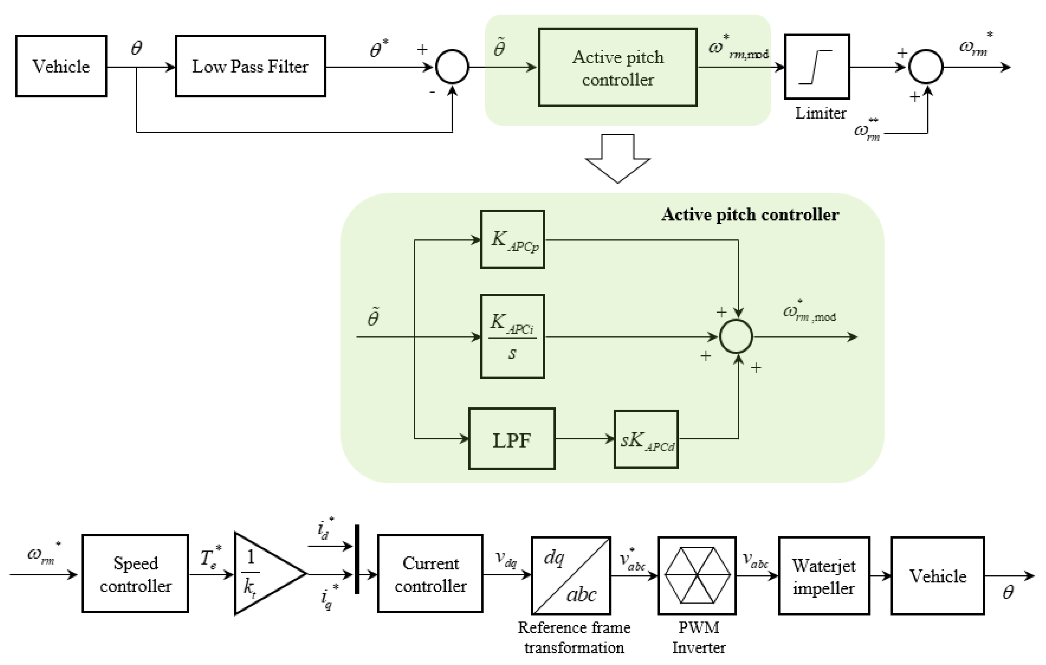
In this study, the effectiveness of the pitch motion control of an AAV was experimentally verified through the impeller revolution rate control of a motor-driven waterjet propulsion system. The real-time pitch angle was passed through an LPF to generate motion commands. The controller was configured to follow the command value by passing the difference between the generated command and the current pitch angle to the input of the controller. In order to minimize the change in design speed, the final speed command was generated by limiting the PID controller output to a certain range.
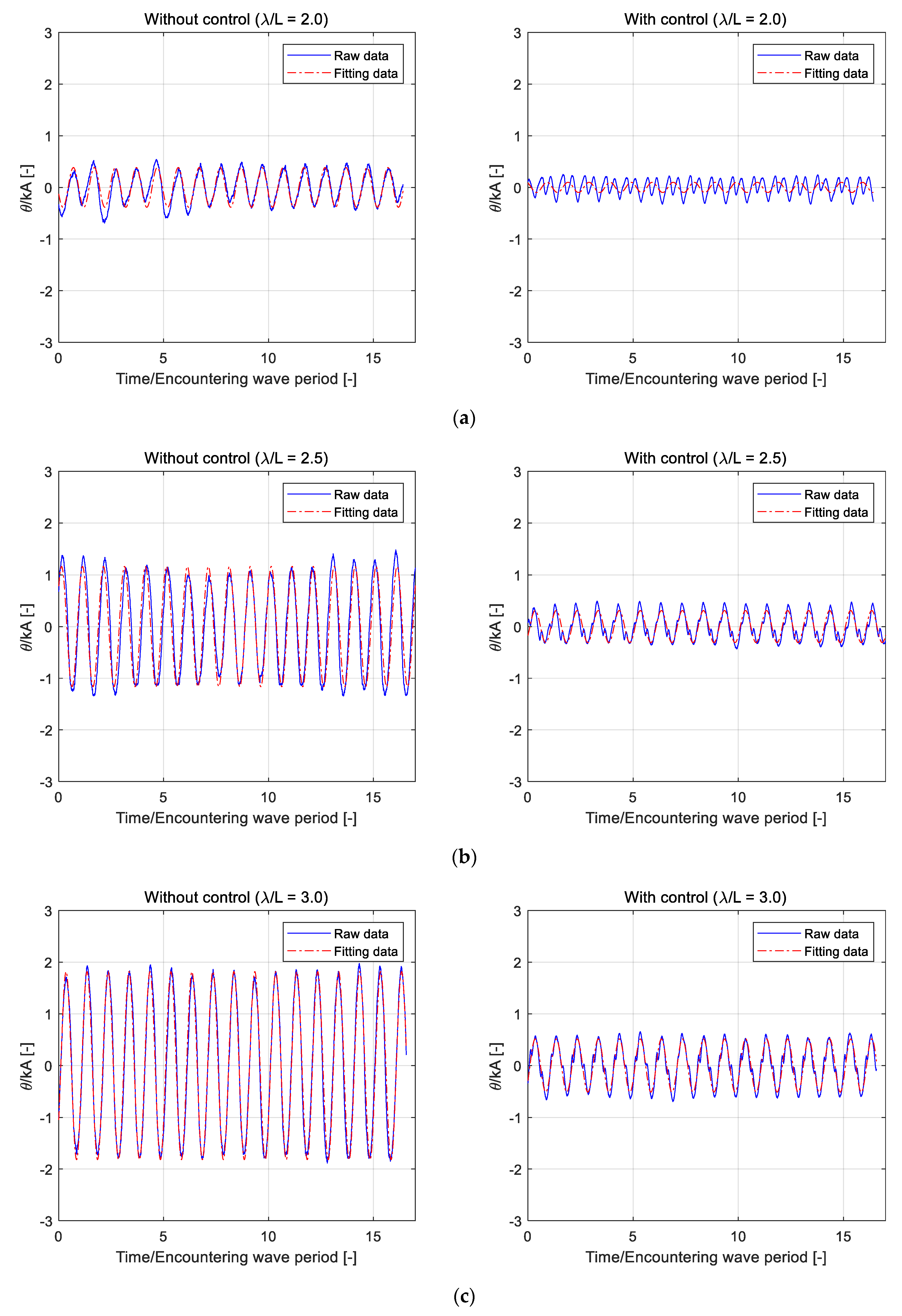
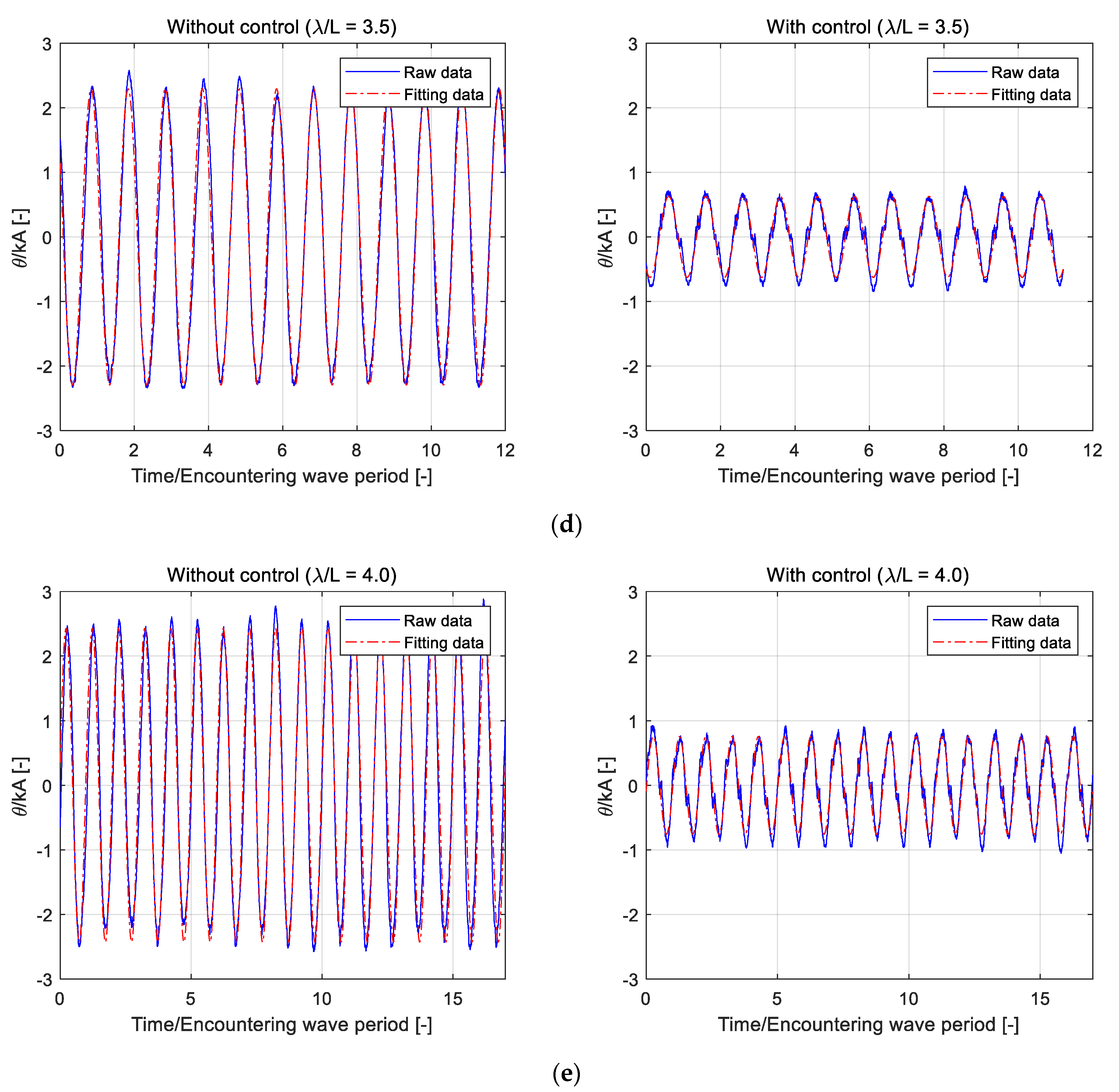
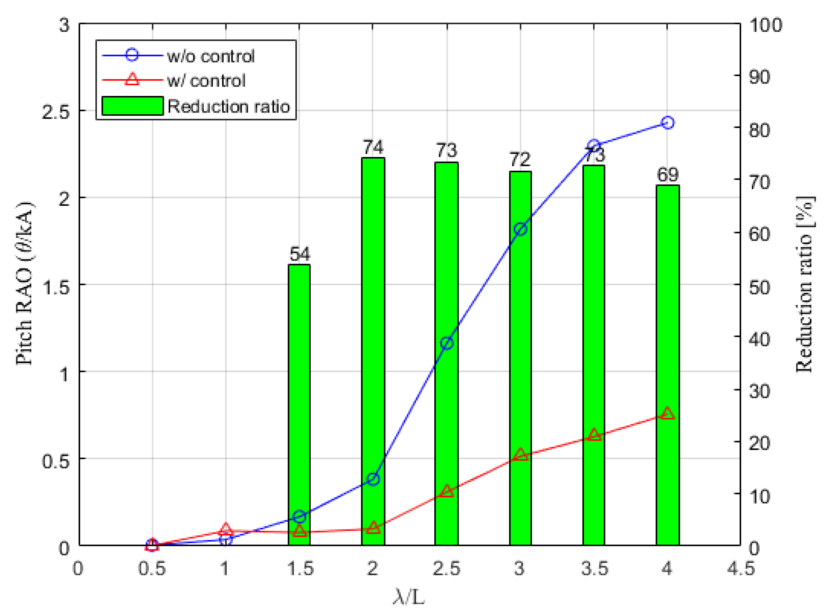
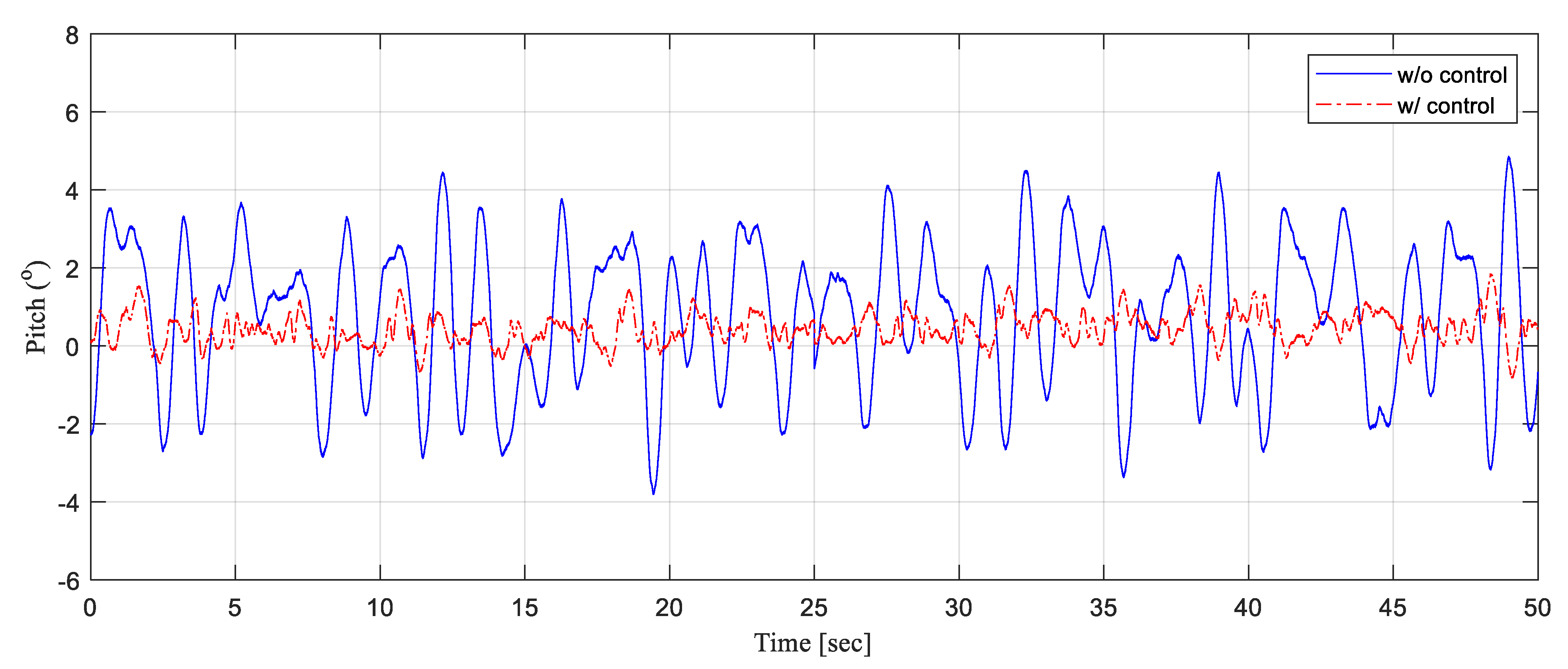
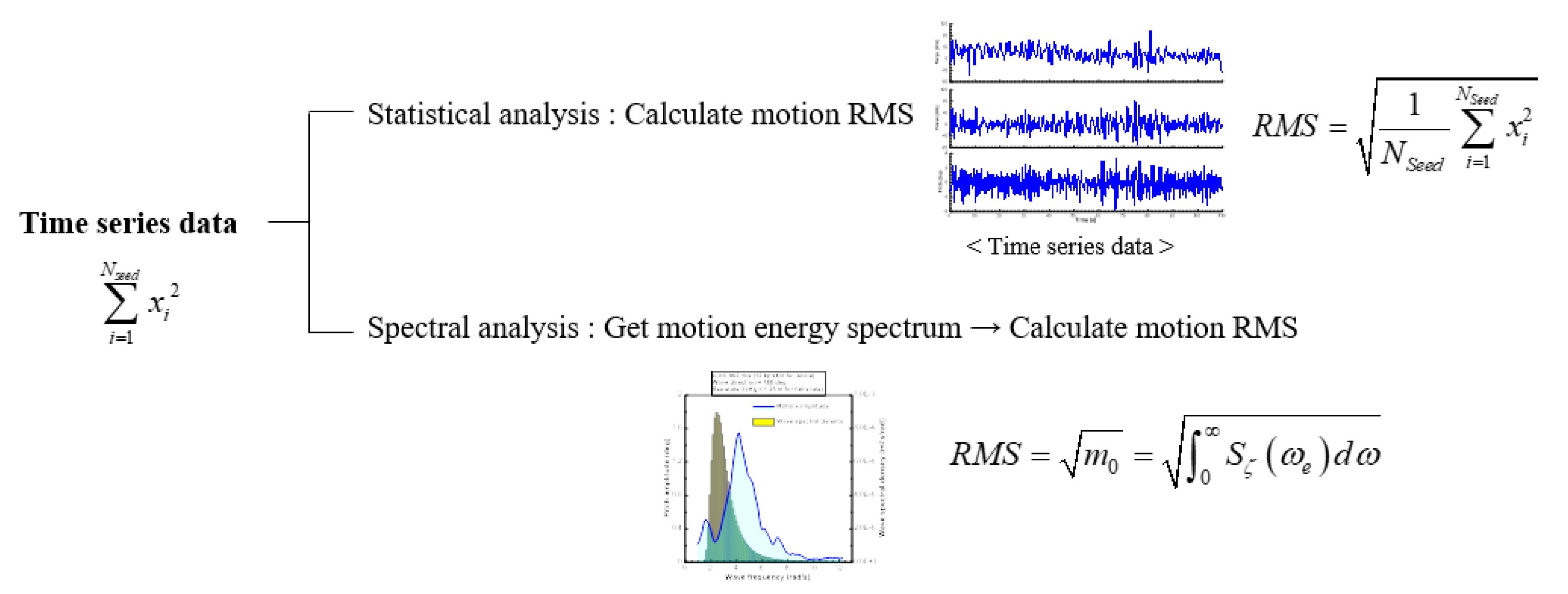
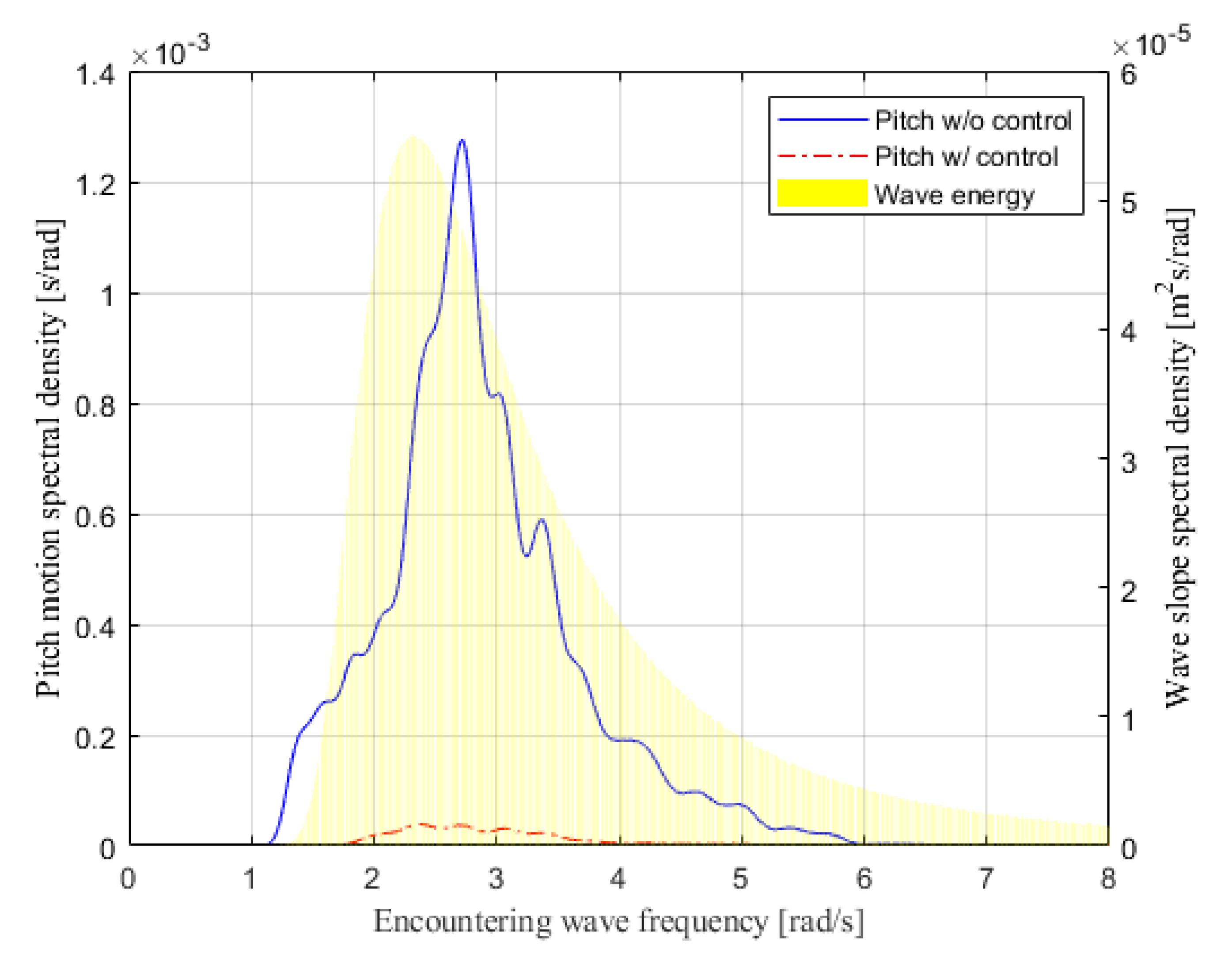
The seakeeping tests in regular waves were performed with and without control at eight regular wave frequencies. As the wavelength increases, the response of the pitch increases, showing a tendency of typical motion characteristics. When control is applied, the tendency of the pitch response shows a similar result to that of the case where the controller is not activated, and most of the motion responses are reduced by about 70% in the frequency region where the pitch motion largely occurs. Since a noticeable decrease in motion is seen in most of the wave frequency ranges, this result is considered to be a remarkable achievement when compared with previous studies. After first checking the performance of the controller in regular wave conditions, the performance of the controller was checked again in the long-crested irregular wave corresponding to sea state 2. Two methods were applied to analyze motion data according to whether or not a controller is applied in an irregular wave environment. The first one is a statistical analysis that directly estimates RMS from time-series data, and the second one is a spectral analysis that estimates RMS by transforming the data in the time domain to the frequency domain. It was confirmed that both methods showed similar results. When the controller was applied, the result was that the pitch RMS decreased by more than 60%. In general, the pitch motion is the largest in the head wave, so even if it results from performing the model tests only in the head wave, it is considered a control performance that can be practically applied.
Since pitch motion is prominent in the head sea condition, the worst case of the head sea condition in terms of seakeeping ability was mainly analyzed. However, in other wave direction conditions such as bow sea and beam sea, it may be necessary to change the gain of the controller designed in the head sea condition. The results of this study show the results of the towing tank experiment, that is, basic research, to test the performance of reducing pitch motion by applying a controller. Although the performance was sufficiently verified by model tests, a more reliable performance verification is required by free-running model tests for the designed controller. In addition, we plan to perform system identification to estimate parameters including added mass and damping coefficients of heave-pitch coupled equations of motion by using the data measured through the free-running model tests. It is believed that more effective controller tuning can be performed by using the equations of motion identified through the system identification. Moreover, this experiment re-emphasizes that the focus is applied only to the pitching motion control in the head sea condition, and the change of waterjet rpm to control the pitch can affect other motions such as roll and heave. From this study, it is considered as a matter to be continued in the future.

Author Contributions

Conceptualization, D.L. and S.K.; methodology, M.J.; software, Y.C.K.; validation, D.L., S.K. and M.J.; formal analysis, J.P.; investigation, D.L.; writing—original draft preparation, D.L. and S.K.; writing—review and editing, D.L.; supervision, S.H.R.; project administration, S.H.R.; funding acquisition, T.H.K. All authors have read and agreed to the published version of the manuscript.

Funding

This research was funded by Agency for Defense Development.

Institutional Review Board Statement

Not applicable.

Informed Consent Statement

Not applicable.

Data Availability Statement

Not applicable.

Acknowledgments

This research was financially supported by the Agency for Defense Development, and Geuk-sang Yoo provided enormous technical support during the experiment.

Conflicts of Interest

The authors declare no conflict of interest.

References

  1. Helvacioglu, S.; Helvacioglu, I.H.; Tuncer, B. Improving the river crossing capability of an amphibious vehicle. Ocean Eng. 2011, 38, 2201–2207. [Google Scholar] [CrossRef]
  2. Lee, S.-J.; Lee, T.-I.; Lee, J.-J.; Nam, W.; Suh, J.-C. Hydrodynamic Characteristics of a Hydrofoil-assisted Amphibious Vehicle. J. Ship Res. 2017, 61, 15–22. [Google Scholar] [CrossRef]
  3. Allison, J.L. Marine waterjet propulsion. Trans. Soc. Nav. Archit. Mar. Eng. 1993, 101, 275–335. [Google Scholar]
  4. Katayama, K.; Suzuki, K.; Ikeda, Y. A new ship motion control system for high-speed craft. In Proceedings of the FAST 2003 The 7th International Conference on Fast Sea Transportation, Ischia, Italy, 7–10 October 2003; pp. 17–24. [Google Scholar]
  5. Santos, M.; Lopez, R.; De La Cruz, J. Fuzzy control of the vertical acceleration of fast ferries. Control Eng. Pract. 2005, 13, 305–313. [Google Scholar] [CrossRef]
  6. Karimi, M.H.; Seif, M.S.; Abbaspoor, M. A study on vertical motions of high-speed planing boats with automatically controlled stern interceptors in calm water and head waves. Ships Offshore Struct. 2015, 10, 335–348. [Google Scholar] [CrossRef]
  7. Choi, H.; Park, J.; Kim, D.; Kim, S.; Lee, J.; Ahn, J. System identification and pitch control of a planing hull ship with a controllable stern intercepter. J. Soc. Nav. Archit. Korea 2018, 219, 401–414. [Google Scholar] [CrossRef] [Green Version]
  8. Park, J.Y.; Choi, H.; Lee, J.; Choi, H.; Woo, J.; Kim, S.; Kim, D.J.; Kim, S.Y.; Kim, N. An experimental study on vertical motion control of a high-speed planning vessel using a controllable interceptor in waves. Ocean. Eng. 2019, 173, 841–850. [Google Scholar] [CrossRef]
  9. Liu, Z.; Zheng, L.; Li, G.; Yuan, S.; Yang, S. An experimental study of the vertical stabilization control of a trimaran using an actively controlled T-foil and flap. Ocean Eng. 2021, 219, 108224. [Google Scholar] [CrossRef]
  10. Sul, S.K. Control of Electric Machine Drive Systems; John and Wiley and Sons: Hoboken, NJ, USA, 2011. [Google Scholar]
Figure 1. Coordinate systems. (a) Earth-fixed coordinate system ( O x y z ); (b) body-fixed coordinate system ( o x b y b z b ).
Jmse 09 00894 g001
Figure 2. Test model of AAV.
Jmse 09 00894 g002
Figure 3. Seoul National University Towing Tank (SNUTT).
Jmse 09 00894 g003
Figure 4. Overall test configuration.
Jmse 09 00894 g004
Figure 5. Schematic of pitch moment by the waterjet and hydrofoil.
Jmse 09 00894 g005
Figure 6. Pitch moment and trim with respect to impeller revolutions.
Jmse 09 00894 g006
Figure 7. Block diagram of the speed control system.
Jmse 09 00894 g007
Figure 8. Schematic illustration of the APC system. (a) pitch RMS of without APC system; (b) pitch RMS of with APC system.
Jmse 09 00894 g008
Figure 9. Reference generating method. (a) low-pass filter; (b) high-pass filter.
Jmse 09 00894 g009
Figure 10. Block diagram of the active pitch control system.
Jmse 09 00894 g010
Figure 11. Trim angle and rise according to Froude number.
Jmse 09 00894 g011
Figure 12. ITTC standard wave energy spectrum.
Jmse 09 00894 g012
Figure 13. Comparison of time series measurements. (a) λ / L = 2.0 ; (b) λ / L = 2.5 ; (c) λ / L = 3.0 ; (d) λ / L = 3.5 ; (e) λ / L = 4.0 .
Jmse 09 00894 g013aJmse 09 00894 g013b
Figure 14. Comparison of pitch RAO.
Jmse 09 00894 g014
Figure 15. Comparison of time series measurements.
Jmse 09 00894 g015
Figure 16. Analysis method for motion data in irregular waves.
Jmse 09 00894 g016
Figure 17. Wave slope and motion energy spectrum.
Jmse 09 00894 g017
Table 1. Principal dimensions of scale model of the test model.
ItemSymbolFull ScaleTest Model
Vehicle length L 10.22 L
Vehicle width or breadth B 10.22 B
Design draft T 10.22 T
Bow plate incline angle 35° (upper), 15° (lower)
Hydrofoil incident angle
Table 2. Details of regular wave conditions.
λ / L T [ s ] H [ m m ] A / L U [ m / s ]
0.50.76180.0201.57
1.01.07360.0201.57
1.51.32360.0131.57
2.01.52360.0101.57
2.51.70360.0081.57
3.01.86360.0071.57
3.52.01360.0061.57
4.02.15360.0051.57
Table 3. Statistical values in sea state 2 of full case and scale model case.
Item [Unit]FullModel
H 1 / 3 [ m ] 0.30.067
T p [ s ] 6.32.97
Table 4. Comparison of pitch RMS.
ItemPitch RMS [°]
Operating Statistical AnalysisSpectral Analysis
w/o Control1.8761.850
w/Control0.7290.726
Publisher’s Note: MDPI stays neutral with regard to jurisdictional claims in published maps and institutional affiliations.

