Article

Investigation of Non-Linear Ship Hydroelasticity by CFD-FEM Coupling Method

1
School of Naval Architecture, Dalian University of Technology, Dalian 116024, China
2
State Key Laboratory of Deep Sea Mineral Resources Development and Utilization Technology, Research Institute of Mining and Metallurgy, Changsha 410012, China
3
State Key Laboratory of Structural Analysis for Industrial Equipment, Dalian 116024, China
4
Collaborative Innovation Center for Advanced Ship and Deep-Sea Exploration, Shanghai 200240, China
5
CED Group, University of Southampton, Southampton S0167QF, UK
*
Authors to whom correspondence should be addressed.
J. Mar. Sci. Eng. 2021, 9(5), 511; https://doi.org/10.3390/jmse9050511
Submission received: 13 April 2021 / Revised: 30 April 2021 / Accepted: 4 May 2021 / Published: 9 May 2021
(This article belongs to the Section Ocean Engineering)

Abstract

:
With the increase of ship size, the stiffness of the hull structure becomes smaller. This means that the frequency of wave excitation tends to be closer to the natural frequency of the hull vibration, which in turn makes the hydroelastic responses more significant. An accurate assessment of the wave loads and motion responses of hulls is the key to ship design and safety assessment. In this paper, the coupled CFD (Computational Fluid Dynamics)-FEM (Finite Element Method) method is used to investigate the non-linear hydroelasticity effect of a 6750-TEU (Twenty-foot Equivalent Unit) container ship. First, by comparing the heave, pitch, and vertical bending moment at midship section (VBM4) against experimental results reported in the literature, the validity of the numerical method in this paper is illustrated. Secondly, the ship responses under different wave length–ship length ratio, wave frequency-structure natural frequency, wave steepness, and ship speeds are studied. It is found that the wave length–ship length ratio has a more important influence on the hydroelastic response than that from wave frequency-structure natural frequency ratio, and the effect of wave non-linearity will behave differently under different wave length–ship length ratio. The increase of rigid body motion caused by forward speed will not correspondingly increase the non-linearity of the hydroelastic response.

1. Introduction

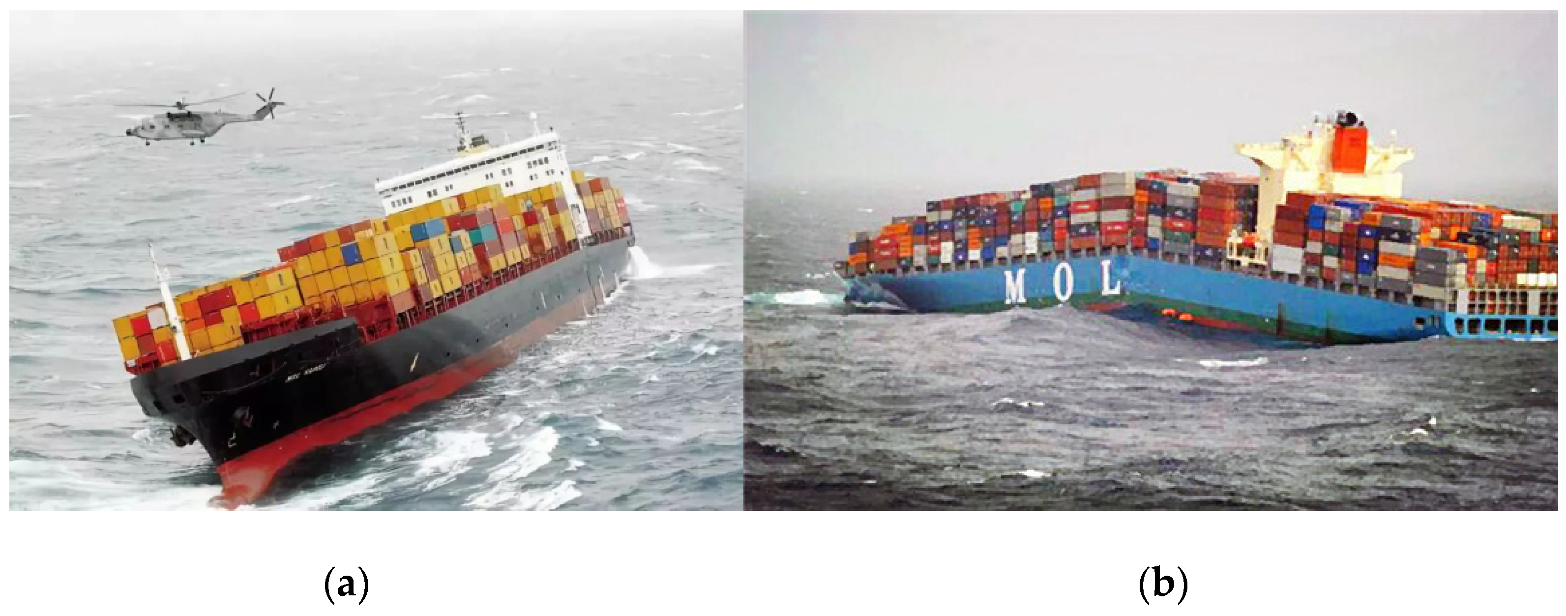
The increase of the scale of modern ships and marine structures means their structure stiffness tends to become smaller. Therefore, the reduction of the natural frequency of the vertical vibration of ship and offshore structure makes the hydroelastic responses such as Spring and Whipping more likely to occur. Thus, the influence of hydroelastic response must be considered. In recent years, some major accidents have occurred due to the failure of the structure linked to the hydroelastic effect. For example, two serious accidents occurred on large container ships, MSC NAPOLI in 2007, and MOL COMFORT in 2013, as shown in Figure 1. It was reported that both vessels were broken due to the large hogging of the hull structure.
The experiment methods considered as an irreplaceable way to study the physics of hydroelasticity and to validate different numerical models. Jiao [1] made a detailed review on the experimental study of ship hydroelasticity. The segmented ship model experiment has become the main method to study the ship hydroelasticity [2,3,4].
On the other hand, the rapid development of different numerical models has made numerical simulation, which has the advantages of relatively low cost and easy for systematically parameter studies, as equally important as experimental approaches. The theory of ship hydroelasticity has seen a process from potential flow to viscous flow, from two-dimensional (2D) to three-dimensional (3D), and from linear to nonlinear [5]. The 2D hydroelasticity theory consists of 2D strip theory for the fluid dynamics and mode superposition method for structure dynamics [6,7,8]. The work by Bishop and Price [9] is one of the milestones of the 2D hydroelasticity theory. Wu [10] pioneered the 3D linear hydroelasticity theory, which can be used to solve arbitrary variable bodies in waves. Price [11] modified this theory so that the viscous resistance of fluid could be taken into account in the calculation. Based on the original 2D and 3D linear hydroelasticity theory, many scholars proposed 2D and 3D nonlinear hydroelasticity theories by considering a series of nonlinear factors. Some typical works include Yamamoto’s nonlinear 2D strip model [12] and the systematic works of Wu [13,14,15] that combines linear model and impulse type theory for high-speed ships. There are also many works on Boundary Element Method (BEM) based models for hydroelasticity problems [16,17,18].
The abovementioned potential flow-based theories have been widely used for hydroelasticity computations, but the basic assumptions of the theory make it difficult to directly simulate the non-linear factors such as wave breaking or large body motions. On the other hand, the CFD (Computational Fluid Dynamics) technology, which is based on solving RANS (Reynolds-Averaged Navier-Stokes) equation, can easily take all these non-linear factors into account. By further coupling it with Finite Element Method, the CFD-FEM method such as the work by Lakshmynarayanana [19] can theoretically capture all the non-linear factors in the fluid and structure interaction process. According to whether the structure deformation feedback is taken into account for flow computation, the fluid structure interaction problem is divided into one-way and two-way coupling. Dhavalikar [20] compared the results calculated by one-way coupling with experimental results and found the results are larger than the experimental results, Paik [21] calculated the hydroelasticity of container ships by two methods and found that the results of two-way coupling calculation were closer to the experimental results. These works all indicate the necessity of two-way coupling, i.e., taking the structure deformation into account for hydroelasticity computation.
In the last few decades, many scholars have studied the nonlinearity of ships’ vertical motions and the wave load. Paik [21] made a detailed review of this. Watanabe’s experiments show that the ship’s flare shape has influence on the vertical bending moment peak and pitch motion [22]. Fonseca and Soares also demonstrated by model experiments that the nonlinearity of wave loads is much more significant than that of motion due to the geometry with a large flare at the bow [23]. Some scholars have studied the effects of wave nonlinearity and speed on hydroelastic response. Lakshmynarayanana [19] studied the influence of wave steepness on the structural response of barges under the condition of no speed. Then, Lakshmynarayanana [24] calculated the effect of wave steepness on the structural response of ships with speed at different encounter frequencies. Tian studied the effect of ship speed on the hydroelastic calculation of wave loads on large bulk carriers [25]. Ni studied the effects of wave nonlinearity and speed on the hydroelastic response of large bulk carriers [26]. Yang [27] used a 3D nonlinear hydroelastic method in the time domain to study the nonlinear springing and whipping of a 6750 TEU container ship. Jiao [28] analyzed the hydroelastic response and slamming loads of ships in real waves by large-scale model measurement. From the literature, we found that most of the previous scholars only studied the influence of ship speed and wave nonlinearity on the hydroelastic response, respectively. As an important factor for ship and wave interaction, the wave length–ship length ratio can potentially have a significant influence on the hydroelasticity response, which has not thoroughly investigated in the literature. In this paper, the two-way coupling CFD-FEM method is used to calculate the hydroelastic response of a container ship under the combined influences of various factors, including wave length–ship length ratio, forward speed, and wave steepness.
The following sections are arranged as follows: the basics of the numerical models used in this study is briefly stated and validated in Section 2 and Section 3, respectively. Then, in Section 4, the hydroelastic responses with and without forward speed are investigated in more details; and finally, the conclusion is drawn in Section 5.

2. The Numerical Method

2.1. CFD Model

The governing equations of the flow field are continuity equation and Reynolds Averaged Navier Stokes (RANS) equation, which is expressed as follows.
u i ¯ x i = 0
ρ [ u i ¯ t + ( u i u j ¯ ) x j ] = p ¯ x i + μ 2 u i ¯ + x j ( ρ u i u j ¯ )
where ρ is density, μ is turbulent viscosity. u ¯ is the time average of velocity, p ¯ is the time average of pressure, ρ u i u j ¯ is the turbulent stress term.
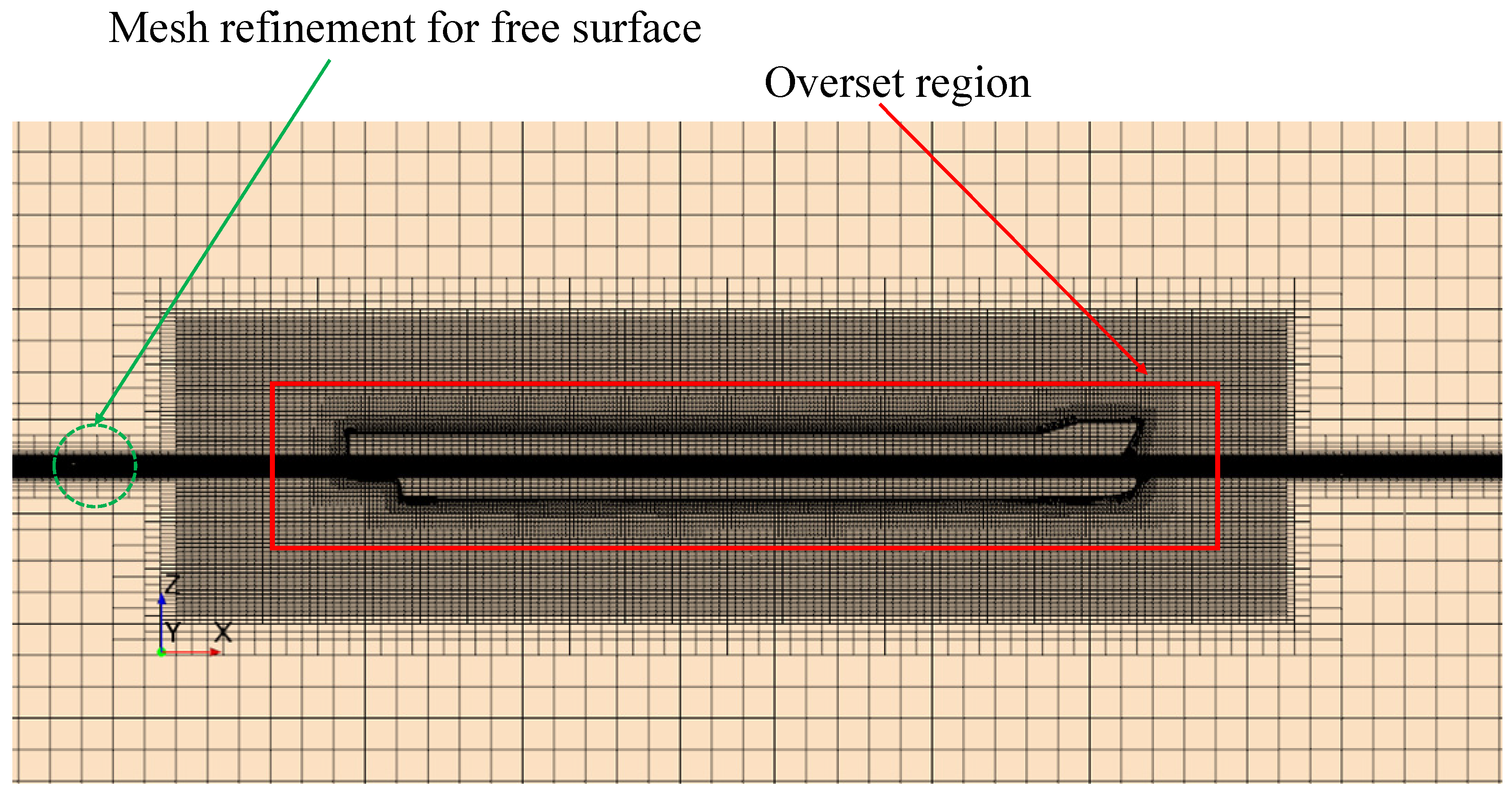
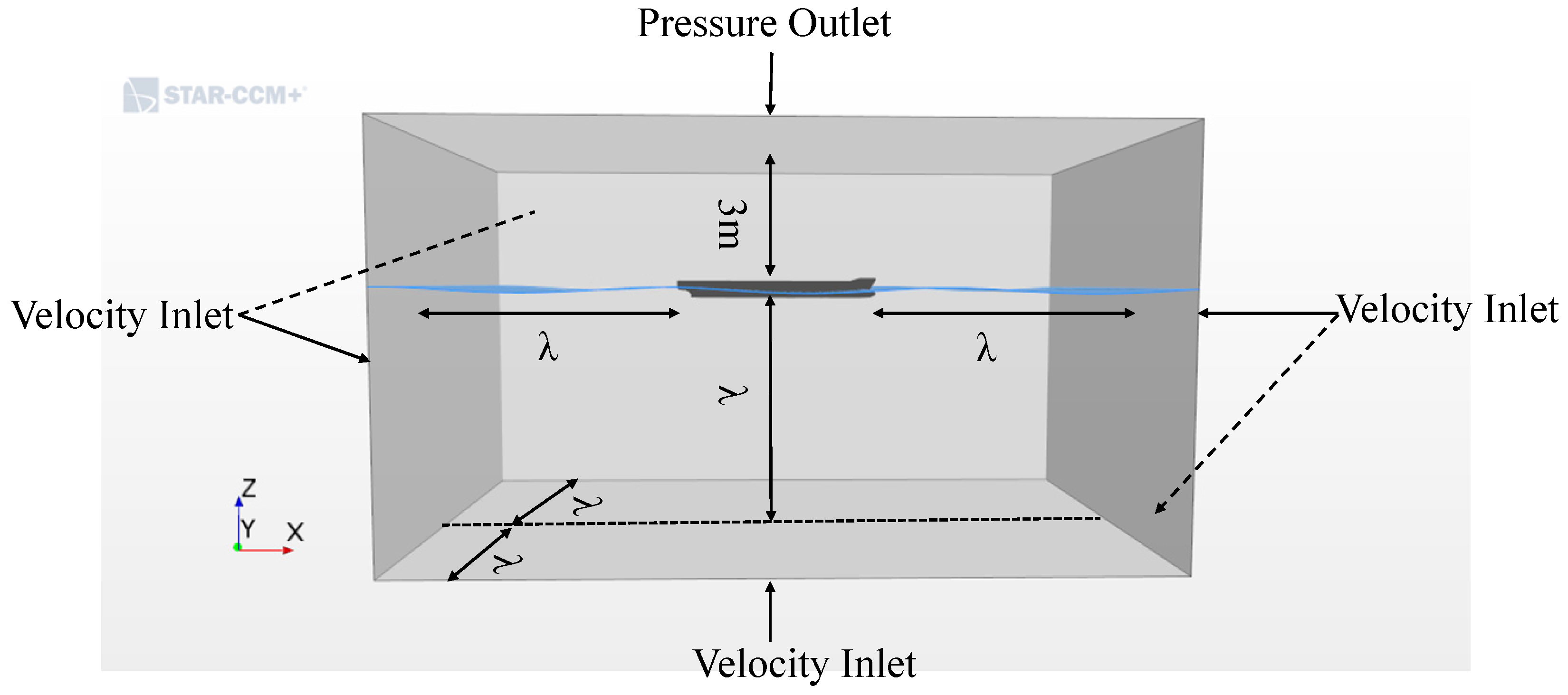
The CFD software STAR-CCM+ is used for the simulation. The spatial discretization method of flow field is finite volume method. In the discrete flow space, the “Separated Flow Solver” is used in the coupling calculation, which uses SIMPLE (Semi-Implicit Method for Pressure-Linked Equations) algorithm to solve the velocity and pressure of the flow field [29,30]. Euler multiphase flow is used to model the air and water phases. Then, the VOF (Volume of Fluid) method is used to capture the free surface between two phases [31]. The k-ε model is used for modeling the flow turbulence. The fifth order Stokes waves is adopted by specifying velocity conditions on the flow inlet boundary [30,32]. Besides, the “VOF Wave Forcing” is used on the outlet boundary of the computation domain, which added a source term to the transport (momentum) equations of a zone outside the computation zone to eliminate the reflections of surface waves at boundaries. Kim [33] gives a more detailed theoretical explanation of this method. A “Pressure Outlet” boundary condition is used for the top of the computational domain. The detailed size of the computational domain is shown in Figure 2. The flow field is discretized by trimmed grid. The overset mesh and mesh deformation called “morpher” are used in the domain covering the hull (As shown in Figure 3). The overset mesh allows the ship to move freely with large amplitude. The overset mesh method has high computational efficiency and accuracy in solving the problem of the structure having a large amplitude of motion. Therefore, it has been widely used in the numerical calculation of many engineering problems [34,35,36,37,38]. The mesh deformation is updated according to the displacement feedback from the structure. The area near the free surface is divided into 80 grids per wave length and 20 grids along wave height direction [30]. The overall meshing is shown in Figure 3.

2.2. FEM Model

The governing equation for structure dynamics is shown as follows:
M   u ¨ + C   u ˙ + K   u = F
where M is the mass of the structure, C is the damping of the structure, K is the stiffness of the structure, u is the displacement of the structure,   u ˙ and   u ¨ are the velocity and acceleration of the structure, and F is the external force on the structure. It should be noted that the damping of the structure is not considered in this paper [19].
The FEM software ABAQUS [19,39] is used to solve the motion of the structure. A total of 144 B31 type elements are used to model the beam of the container ship, 12,618 three node triangular membrane elements SFM3D3 are used to model the hull [19]. The concentrated mass points are distributed along the longitudinal direction of the hull girder, the mass distribution of the finite element model is consistent with the model of the experiment in Kim’s article [3]. Membrane elements can only transfer the fluid force to beam elements. The beam will deform according to the hydrodynamic force acting on the structure and the membrane elements do not carry any load, i.e., the membrane element and beam element are connected by kinematic coupling constraints [39], which means the displacement of the membrane element is the same as that of the control nodes of the beam element. The finite element calculation model is shown in Figure 4.

2.3. Coupling between Fluid and Structure Solvers

The pressure data in flow field and displacement data in structure solver are exchanged through the coupling surface. Fluid pressure and shear force, which are exported from flow field, are enforced as boundary conditions for structure solver. The structure displacement, which is exported from structure solver, is used as boundary condition for fluid solver. The implicit coupling is adopted, which allows multiple data exchange between flow and structure solver in a fixed time step. The time step Δ t = T e 2.4 × 80 (where T e is the encounter period).

3. Numerical Model Validation

The results of the hydroelastic model test of the 6750-TEU container ship in KRISO Institute are used to verify the numerical calculation results in this paper. The experimental model of container ship is made by elastic beam and segmented hull. Kim has given a very detailed introduction to the information of the model experiment [3,27]. The three-dimensional geometric model of 6750-TEU container ship is shown in Figure 5. The body plan of the 6750-TEU containership can be found in reference [3,27]. The principal dimensions of the 6750-TEU containership are shown in Table 1.
The numerical model used in this paper has been validated against experimental results [3] in our previous work [40]. For the sake of simplicity, only a brief review of the comparison between numerical and experimental results is given in this section.
The rigid body responses such as heave, pitch and hydroelastic response, i.e., vertical bending moment at Section 4 (VBM4) near the amidship are compared. The results under one of the typical non-linear wave conditions, which is called NL1, is shown in Table 2 (H is the wave height, λ is the wave length, β is the heading angle).
In order to check the grid convergence performance, three sets of meshes, which are shown in Table 3, are generated for the same condition mentioned above.
As shown in Figure 6, the results from three sets of meshes are very close to each other, which shows good mesh convergence property of the numerical model. The type b (4.6 million mesh) is selected in this paper considering the accuracy and efficiency of calculation. Moreover, the results marked by “Max”, “Min”, and “Mean” (which means maximum, minimum, and mean values, respectively) are obtained by analyzing several different types of numerical methods (most of them are potential flow based methods) as reported in Kim’s article [3]. “Exp” represents the experimental value. It is worth noting that the various numerical models mentioned in ref [3] show a large variation between different models (most of which are potential flow based methods), which deviate from the experimental values by a relatively large amount. The current CFD-FEM coupled model shows a comparable level of accuracy as the “mean” value of the other numerical models (compared with experimental values). In terms of the most concerned hydroleasticity results, i.e., vertical bending moment time series at midship (Figure 6c) and spatical distribution along the ship length (Figure 6d), the current CFD-FEM results show better accuracy. More specifically, compared with experimental results, the maximum relative error of the VBM4 time series by the current CFD-FEM model is about 2.5% (type b grid), whereas the mean value of other models in ref [3] is about 4.3%. For the vertical bending moment spatical distribution, the current model shows maximum 5% difference with experimental values, whereas the maximum relative error of mean value of other models in ref is more than 10%.
It is clear that the current numerical model match very well with experimental results and close to the mean value of the results from other numerical models. This confirms the accuracy and reliability of the current numerical model.

4. Results and Discussion

4.1. Hydroelastic Response without Ship Forward Speed

The non-linear hydroelasticity effects under different wave length–ship length ratio, wave frequency-structure natural frequency ratio, wave steepness under no forward speed condition are investigated in this section.
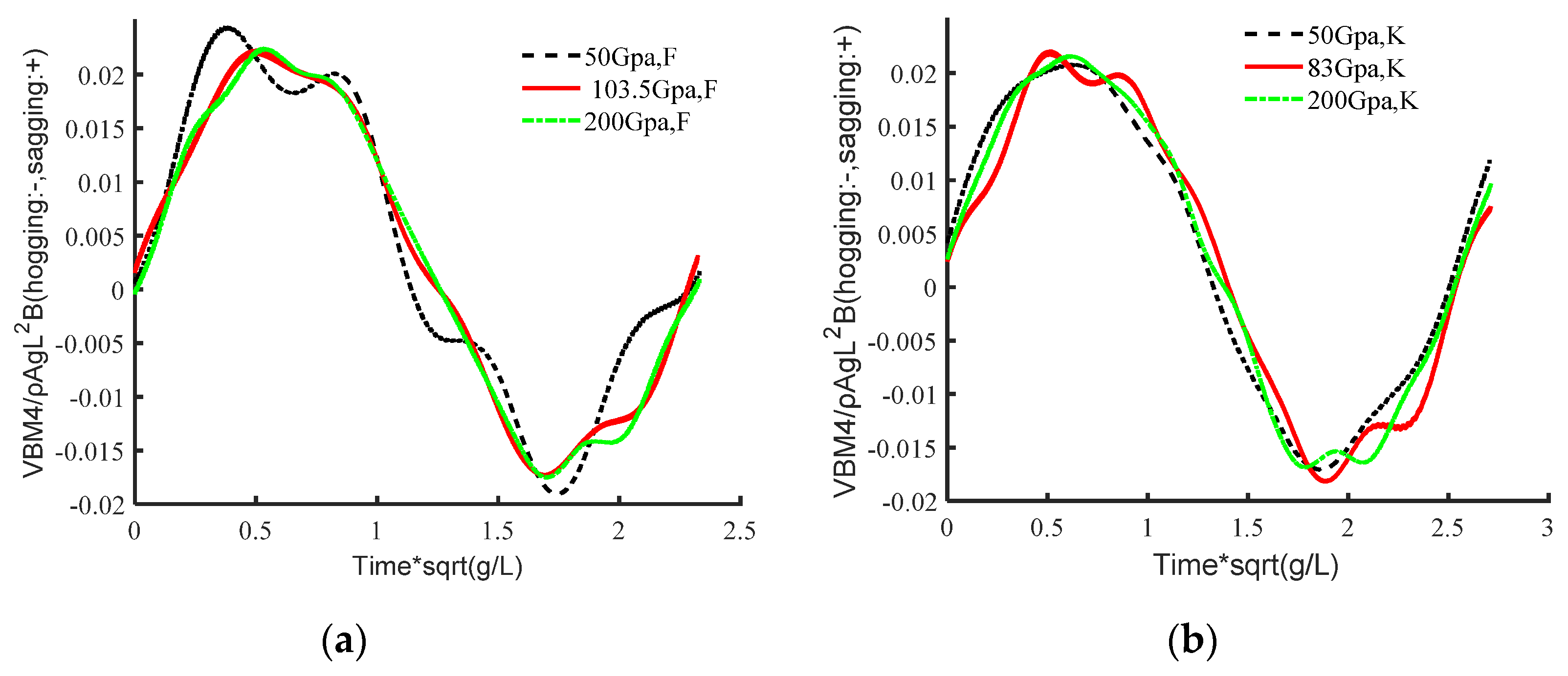
The wave parameters are shown in Table 4, in which ω0 is the wave frequency. It is worth mentioning that the wave steepness of these three wave conditions are kept the same, which is designed to isolate and investigate the effects from the wave length–ship length ratio and wave frequency–structure natural frequency ratio. The vertical bending moment response of the hull structure with different wave frequency-structure natural frequency (2 node bending, the same below) ratios were realized by changing the stiffness of the hull structure as shown in Table 5. (the elastic modulus in the model test mentioned in Section 3 is E = 200 GPa). The natural frequency of hull structures with E = 103.5 GPa, E = 83 GPa and E = 72 GPa were designed to be almost equal to the wave frequencies of cases F, K and M respectively.

4.1.1. Constant Wave Steepness

The non-dimensional vertical bending moment responses of hull structures under three wave conditions are shown in Figure 7. It is found that when λ/L is less than 1 (λ/L = 0.857), the non-dimensional vertical bending moment under low structure stiffness (E = 50 GPa) shows strong non-linearity (Figure 7a). The responses under resonance condition (E = 103.5 GPa) and stiffer case (E = 200 GPa) are very similar. Both are about 9% smaller than that of softer ship hull structure (E = 50 GPa).
When λ/L is close to or larger than 1, the non-dimensional vertical bending moment of the midship section does not show significant difference for different wave frequency-structure natural frequency ratios. More specifically, as shown in Figure 7b, for the case where λ/L = 1.07, the largest non-dimensional vertical bending moment indeed occurs under resonance condition (E = 83 Gpa), but the difference between three cases is only about 5%. When the λ/L is larger than 1, Figure 7c shows that the stiffness of the hull structure has little effect on the non-dimensional vertical bending moment of the midship section as well. The difference between three rigidities is less than 3%.
Overall, the non-linearity of the hydroelastic response is not sensitive to the ratio between wave frequency and structure natural frequency, but affected by the ratio between the wave length and ship length λ/L.

4.1.2. Different Wave Steepness

In this section, the effect of wave nonlinearity (i.e., wave steepness) on the ship hull responses is further investigated under different structure stiffness and wave length–ship length ratios. The wave steepness is changed from 1/28 (as in Table 3) to 1/50 as shown in Table 6. The non-dimensional vertical bending moment of midship section under two different wave steepness for structures with E = 50 Gpa and E = 200 Gpa are analyzed.
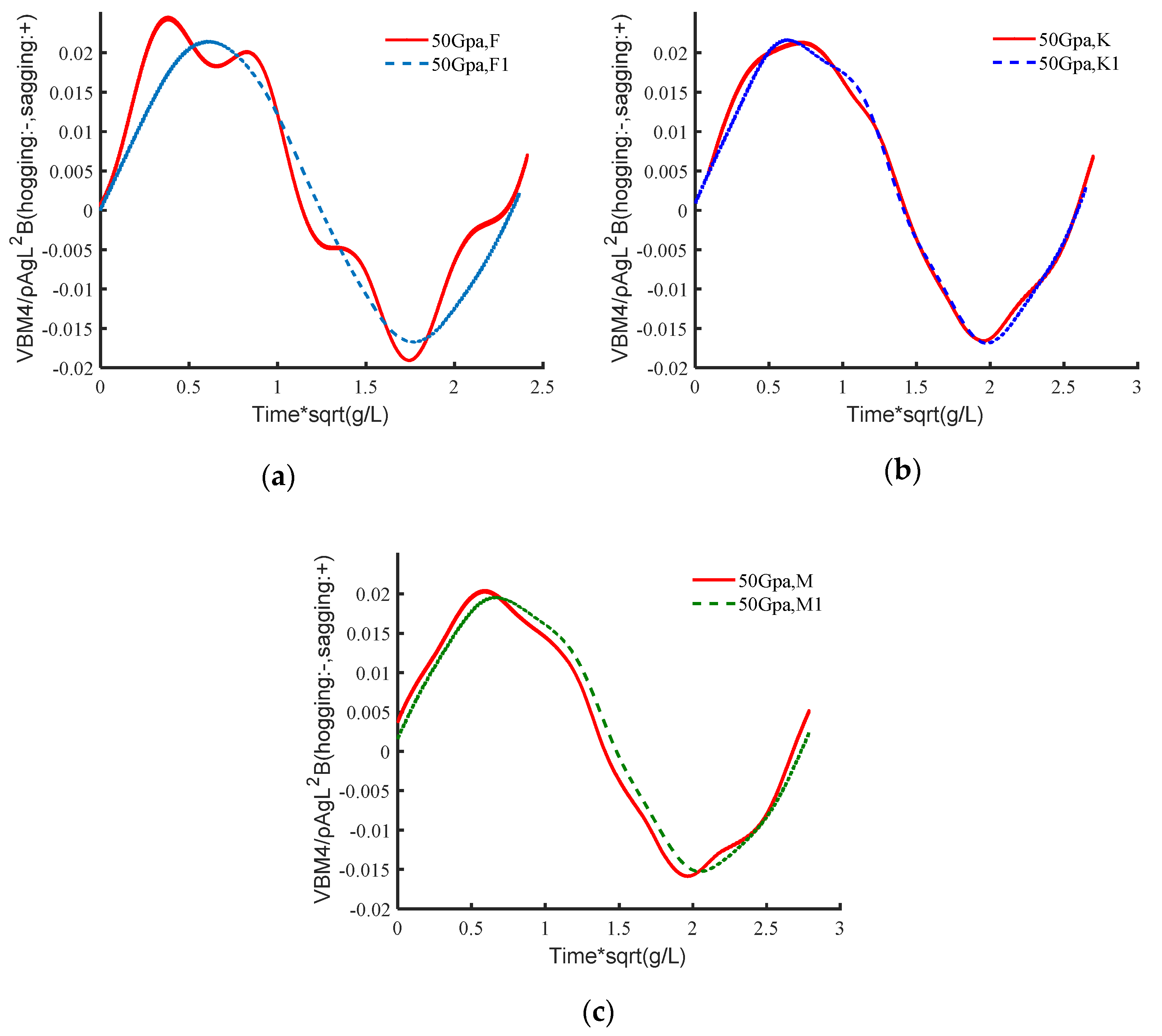
When the elastic modulus of hull structure is E = 50 Gpa, the wave frequencies of the cases in Table 4 and Table 6 are all larger than the structure natural frequency. As shown in Figure 8, the significant wave non-linear effect can only be observed for the case with λ/L is less than 1, i.e., 14% difference as shown in Figure 8a. In addition, the vertical bending moment time-history curve of midship section under wave load F presents significant non-linear characteristics. However, when the wave length–ship length ratio is close to or larger than 1, the wave non-linearity has very little effect on the non-linearity of vertical bending moment. The difference between the amplitude of the non-dimensional vertical bending moment of the midship section between wave load K and K1 is less than 2% and the difference between M and M1 is less than 4%, as shown in Figure 8b,c.
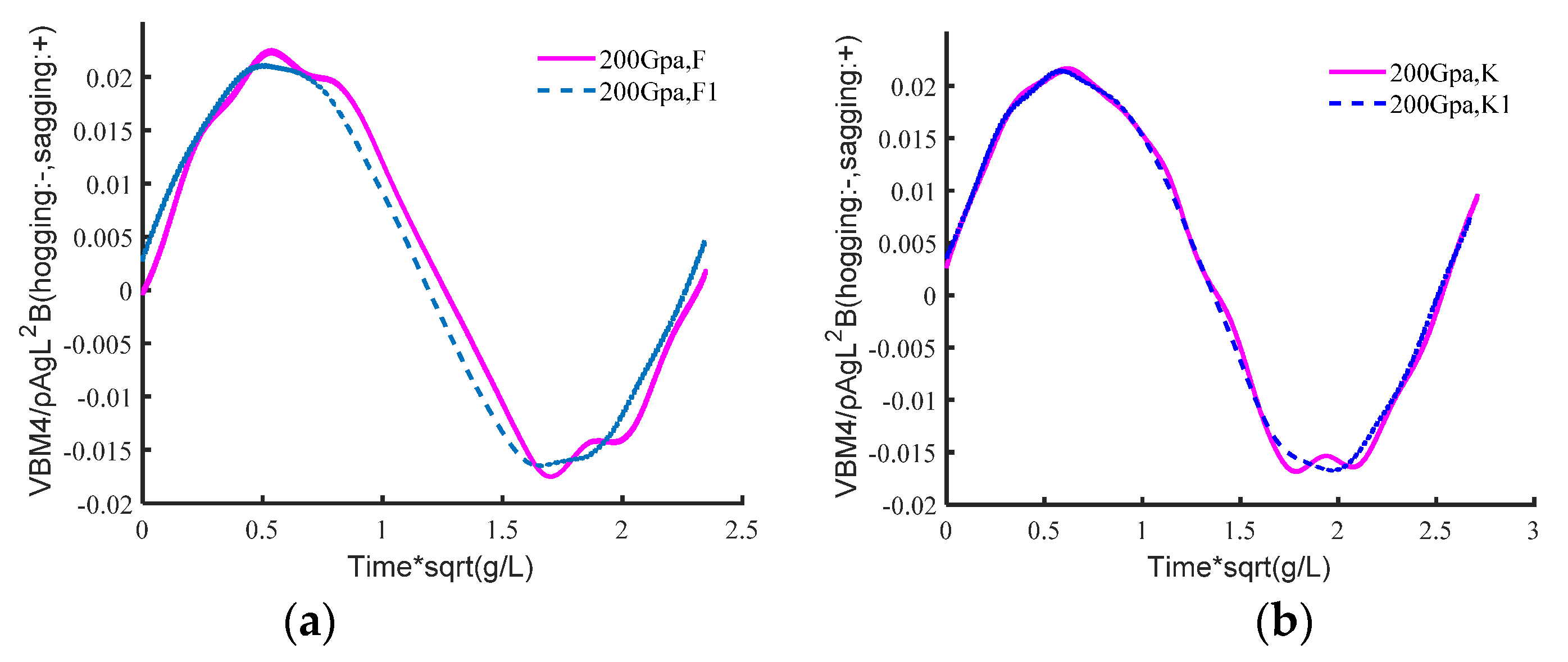
The wave non-linear effect has minor influence on the structure response for cases with relatively high rigidity. More specifically, as shown in Figure 9, for the cases with elastic modulus E = 200 Gpa, in which the structure natural frequency is larger than the wave frequencies, the largest vertical bending moment difference occurs for the cases with λ/L = 0.857 (Figure 9a), but the difference between the cases of wave steepness 1/50 (i.e., F1) and 1/28 (i.e., F) is only about 6%. For the cases with other wave length–ship length ratio as shown in Figure 9b,c, the vertical bending moments difference between different wave steepness (i.e. K and K1, M and M1) are less than 1% and 4% respectively.
It is clear that the effect from wave non-linearity will be more significant when λ/L < 1 under zero forward speed condition. The discussion on cases with forward speeds will be further conducted in Section 4.2.

4.2. Hydroelastic Response with Ship Forward Speed

As discussed in Section 4.1, the hydroelastic response is not sensitive to the ratio of wave frequency and structure natural frequency, i.e., the non-dimensional vertical bending moment shows no significant difference at resonate frequency, however, the non-linear wave effect under different wave length–ship length ratios will behave differently. In this section, the influence of forward speed on the non-linear hydroelasticity response with λ/L = 0.857~1.228 (the same range in Section 4) is further investigated. The elastic modulus E = 200 Gpa of the hull structure is selected for the simulation in this section.

4.2.1. Response with Same Wave Conditions but Different Forward Speeds

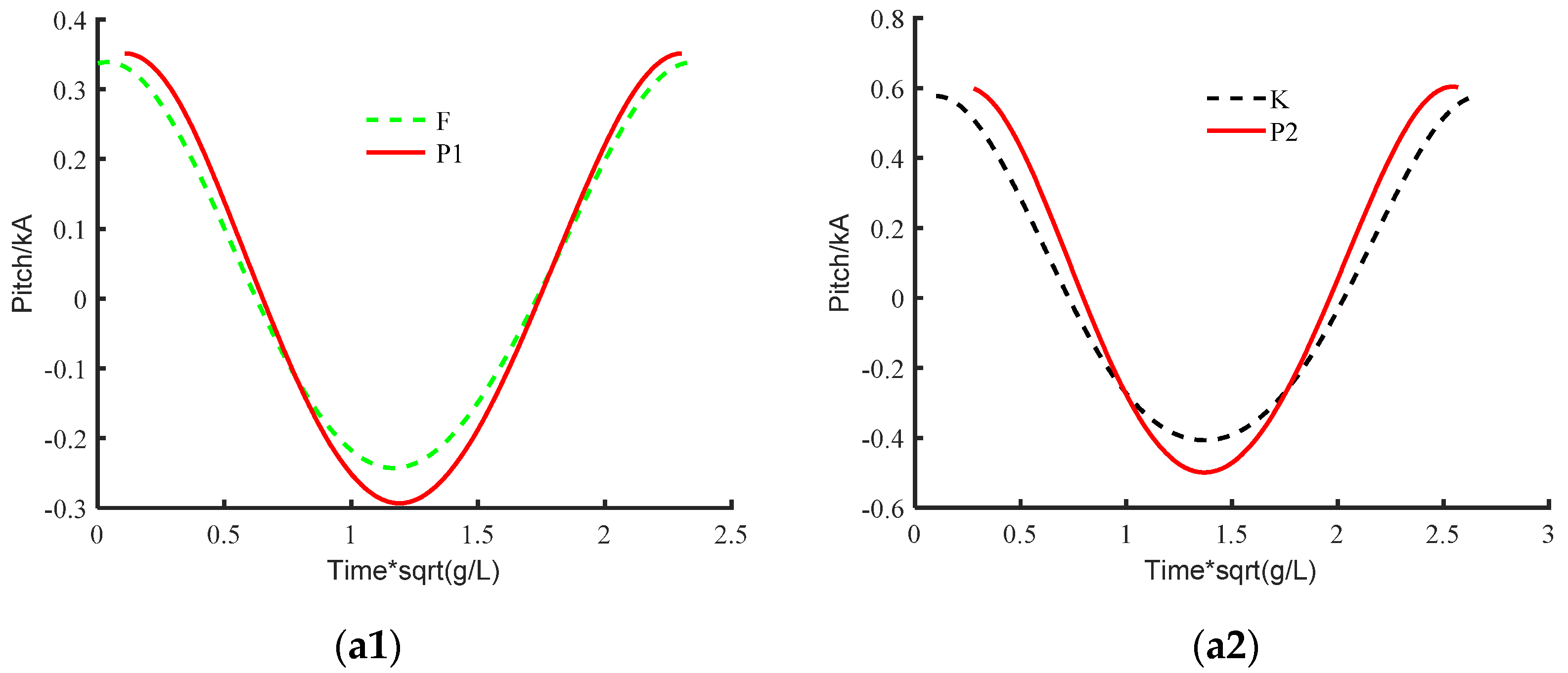
The simulation parameters of different waves are shown in Table 7, in which V is the ship forward speed, the wave steepness is set to be 1/28. The wave conditions in cases P1, P2 and P3 are the same as the conditions of F, K, and M, respectively.
Figure 10, Figure 11 and Figure 12 shows the comparison of structural responses with or without speed for the same wave conditions. The response period is consistent with the excitation period (i.e., the encountered wave frequency) as expected. For the amplitude of the responses, compared with the zero speed cases, it is clear that the ship speed will significantly increase the non-dimensional rigid body motion responses of the ship, i.e., heave and pitch. However, the speed effect on the hydroelastic response is not as much as that on rigid body motion, i.e, the amplitude of the non-dimensional vertical bending moment with forward speed is almost the same with zero speed scenarios results. This indicates that the relatively large rigid body motion caused by forward speed does not correspondingly increase the non-linearity of the hydroelastic response. The wave steepness factor under different λ/L conditions are further discussed below.

4.2.2. Quantitative Comparison of the Nonlinear Factors’ Effects

The non-linearity of the hydroelastic response due to the wave non-linearity, i.e., the wave steepness, are quantitatively investigated in this section. The parameters of the simulations are shown in Table 8.
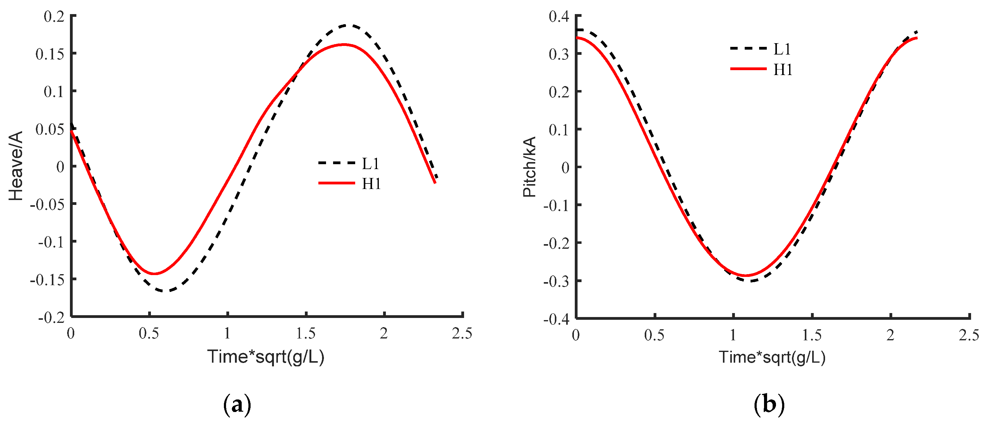
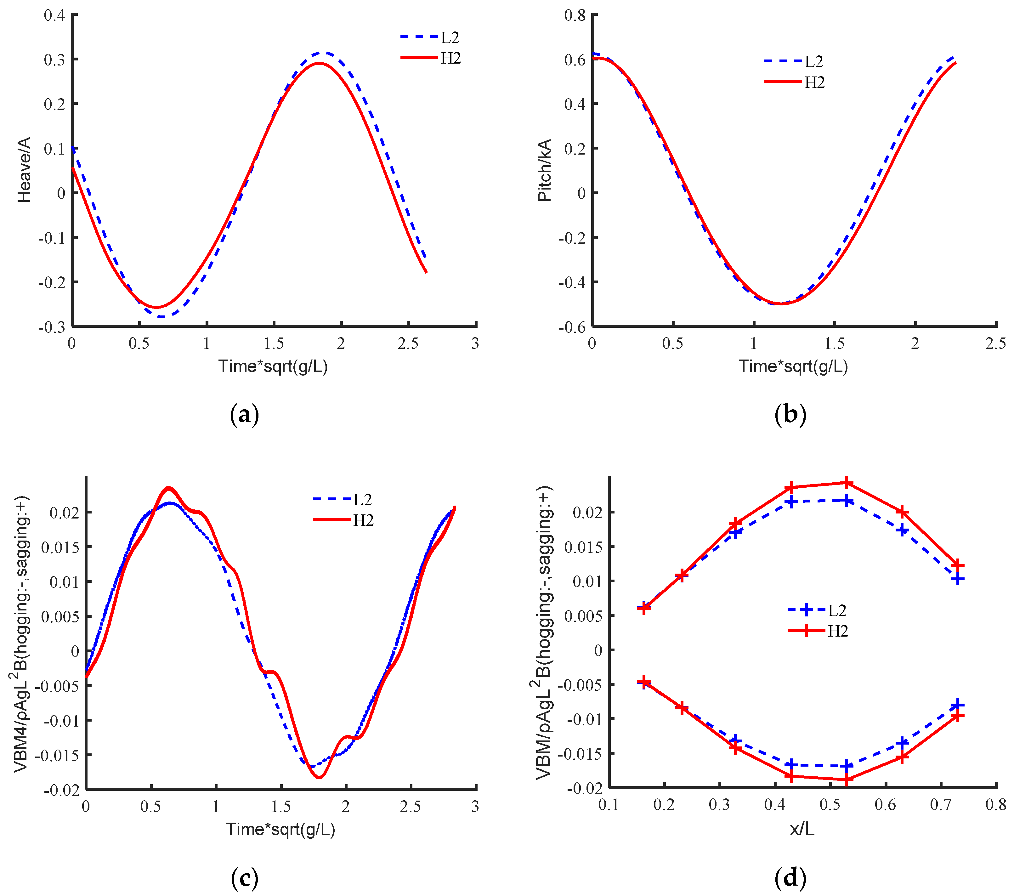
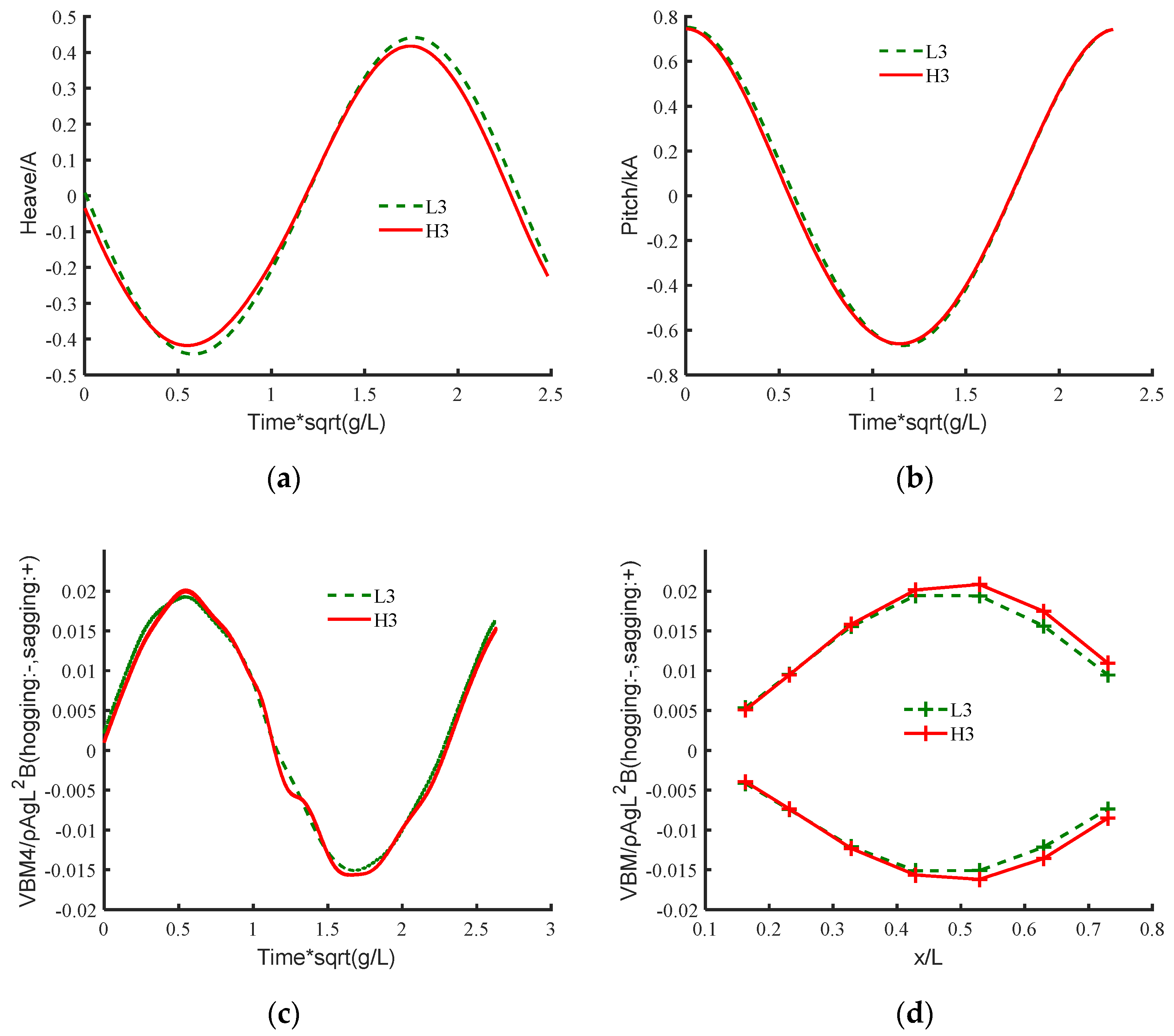
From case L1, L2, L3 to H1 H2, H3, the wave steepness is doubled. As shown in Figure 13, Figure 14 and Figure 15, the non-dimensional heave motion is more sensitive to wave steepness than non-dimensional pitch motion, i.e., with the increase of wave steepness, the non-dimensional heave motion decreases by about 16% (see Figure 13a) and 7% (see Figure 14a and Figure 15a); the non-dimensional pitch motion is almost not changed (see Figure 13b, Figure 14b, and Figure 15b).
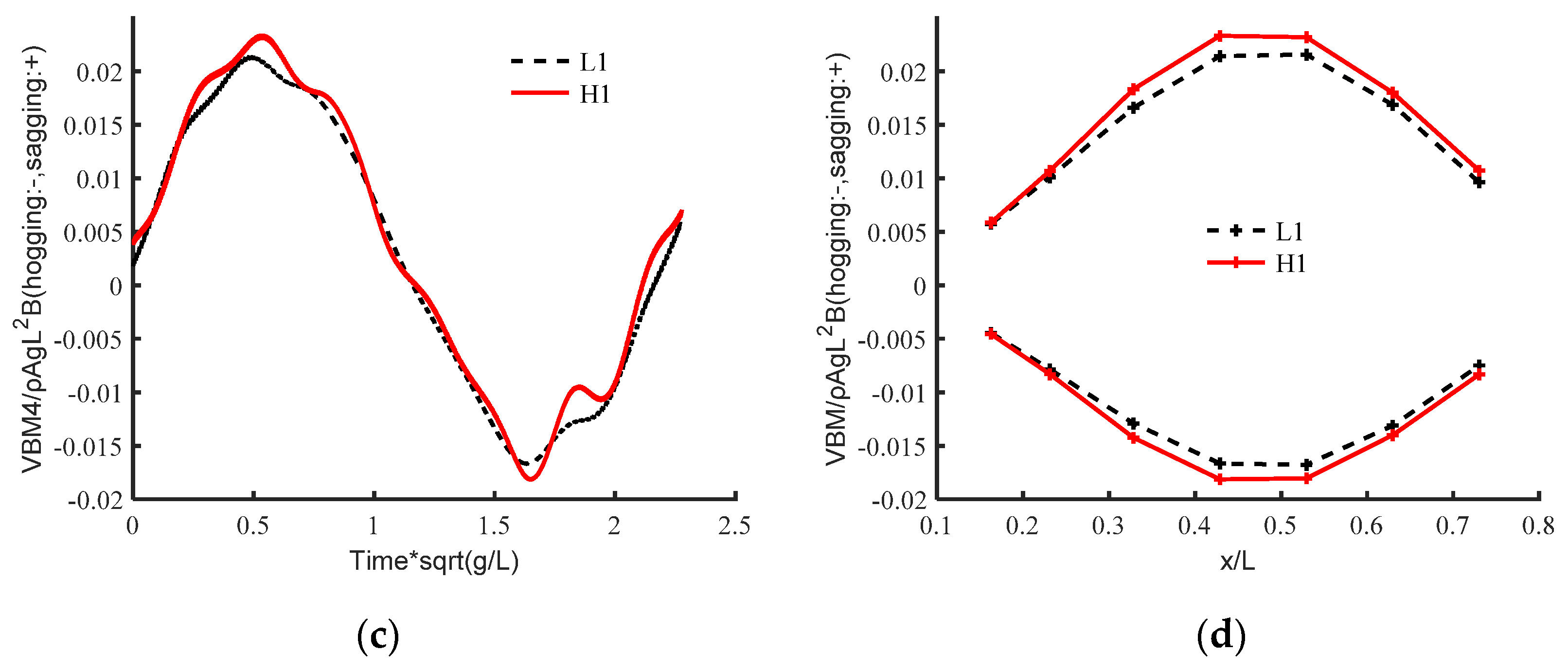
For the hydroelastic response, the cases of L1/H1 and L2/H2 in which λ/L = 0.857 and 1.07 show significant difference for different wave steepness. The non-dimensional vertical bending moment of the midship section increases by about 10% (see Figure 13c and Figure 14c). But for the cases of L3 and H3, the difference is small (Figure 15c). This implies that the influence of wave non-linearity is also affected by λ/L under forward speed condition, i.e., the hydroelastic response is more sensitive to wave steepness when λ/L is smaller or close to 1.
It is found that when the wave steepness increases, the amplitude of the non-dimensional vertical bending moment of Section 4 and Section 5 calculated by H1 increases significantly compared with that of L1, and Section 5 increases by about 7.6% (Figure 13d). The amplitude of the non-dimensional vertical moment of Section 5 calculated by H2 and H3 are about 11.8% and 7.4% larger than those calculated by L2 and L3, respectively. In addition, the increase rate of the amplitudes of the non-dimensional vertical bending moment of the sections near the bow calculated by H2 and H3 is larger (Figure 14d and Figure 15d).

5. Conclusions

In this paper, the coupled CFD-FEM computational method is used for the ship hydroelastic response simulation. The numerical method is firstly validated against the model test results reported in the literature [3]. Then, the hydroelastic response of the model without and with forward speed are calculated, respectively.
For the cases without forward speed, the wave length–ship length ratio has a considerable influence on the hydroelastic responses. For the cases where λ/L is smaller than 1 (0.857 in this case), the non-dimensional vertical bending moments under low structure stiffness (E = 50 GPa in this case) show strong non-linearity instead of the resonance or high rigidity conditions. For the cases where λ/L is equal or larger than 1 (1.07 and 1.228 in this case), the non-dimensional vertical bending moments show no significant difference with different wave frequency-structure natural frequency ratios. The wave non-linearity, i.e., wave steepness, also shows more significant influence under low structure stiffness and λ/L < 1 condition (0.857 in this case).
For the cases with forward speed, the non-dimensional rigid body motions (heave and pitch) will be considerably increased by forward speed under the same wave conditions, but the non-dimensional vertical bending moments are not correspondingly affected by the larger rigid body motion. The non-linearity of waves, i.e., wave steepness, will have a more significant influence on hydroelastic response under the conditions when λ/L is smaller or close to 1 (0.857 and 1.07 in this case).
Author Contributions

Conceptualization, investigation, methodology and validation, Z.S. and G.-J.L.; supervision, Z.S. and L.Z.; resources, Z.S., L.Z. and H.Z.; writing and editing, Z.S., G.-J.L., K.D. All authors have read and agreed to the published version of the manuscript.

Funding

This research was funded by the National Key Research and Development Program of China, grant number 2019YFC0312400 & 2019YFC0312402, National Natural Science Foundation of China, grant number 51809035, Open Project of State Key Laboratory of Deep Sea Mineral Resources Development and Utilization Technology, grant number SH-2020-KF-A01, Liao Ning Revitalization Talents Program, grant number XLYC1908027, and the Fundamental Research Funds for the Central Universities, grant numbers DUT20TD108, DUT20LAB308.

Institutional Review Board Statement

Not applicable.

Informed Consent Statement

Not applicable.

Data Availability Statement

The data presented in this study are available on request from the corresponding author.

Conflicts of Interest

The authors declare no conflict of interest.

References

  1. Jiao, J.; Ren, H.; Sun, S.; Adenya, C.A. Experimental Investigation of Wave-Induced Ship Hydroelastic Vibrations by Large-Scale Model Measurement in Coastal Waves. Shock Vib. 2016, 2016, 1–14. [Google Scholar] [CrossRef] [Green Version]
  2. Jiao, J.; Ren, H.; Sun, S.; Adenya, C.A. Investigation of a ship’s hydroelasticity and seakeeping performance by means of large-scale segmented self-propelling model sea trials. J. Zhejiang Univ.-SCIENCE A 2016, 17, 468–484. [Google Scholar] [CrossRef] [Green Version]
  3. Kim, Y.; Kim, J.-H. Benchmark study on motions and loads of a 6750-TEU containership. Ocean Eng. 2016, 119, 262–273. [Google Scholar] [CrossRef] [Green Version]
  4. Wu, M.; Lehn, E.; Moan, T. Design of segmented model for ship seakeeping tests with hydroelastic effects. In Proceedings of the 6th International Conference on Hydroelasticity in Marine Technology, Tokyo, Japan, 19–21 September 2012; pp. 135–144. [Google Scholar]
  5. Tian, C.; Wu, Y. Review of Research on the Hydroelasticity of Ship(in Chinese). Ship Sci. Technol. 2008, 49, 37–43+48. [Google Scholar]
  6. Betts, C.; Bishop, R.; Price, W. The symmetric generalised fluid forces applied to a ship in a seaway. Int. Shipbuild. Prog. 1977, 199, 265–278. [Google Scholar]
  7. Korvin-Kroukovsky, B.; Jacobs, W. Pitching and heaving motions of a ship in regular waves. Trans. SNAME 1957, 65, 590–632. [Google Scholar]
  8. Salvesen, N. Ship motion and sea loads. Trans. SNAME 1970, 78, 250–287. [Google Scholar]
  9. Bishop, R.; Price, W. Hydroelasticity of Ships; Cambridge University: Cambridge, UK, 1979. [Google Scholar]
  10. Wu, Y. Hydroelasticity of Floating Bodies; Brunel University: Uxbridge, UK, 1984. [Google Scholar]
  11. Price, W.; Wu, Y. The influence of nonlinear fluid forces in the time responses of flexible swath ships excited by a seaway. Proc. OM AE′89 1989, 2, 125–135. [Google Scholar]
  12. Yamamoto, Y.; Sugai, K.; Inoue, H. Wave loads and response of ships and offshore structures from the viewpoint of hydroelasticity. In Proceedings of the International Conferences on Advances in Marine Structure, Dunfermline, UK, 20–23 May 1986. [Google Scholar]
  13. Wu, M.; Hermundstad, O. Time-domain simulation of wave-induced nonlinear motions and loads and its applications in ship design. Mar. Struct. 2002, 15, 561–597. [Google Scholar] [CrossRef]
  14. Wu, M.; Moan, T. Efficient calculation of wave-induced ship responses considering structural dynamic effects. Appl. Ocean Res. 2005, 27, 81–96. [Google Scholar] [CrossRef]
  15. Wu, Y.; Maeda, H.; Kinoshita, T. The second order hydrodynamic actions on a flexible body. SEISAN-KENKYU Inst. Ind. Sci. Univ. Tokyo 1997, 49, 8–19. [Google Scholar]
  16. Kim, K.; Bang, J.; Kim, J.; Kim, Y.; Kim, S.; Kim, Y. Fully coupled BEM-FEM analysis for ship hydroelasticity in waves. Mar. Struct. 2013, 33, 71–99. [Google Scholar] [CrossRef]
  17. Datta, R.; Soares, C. Analysis of the hydroelastic effect on a container vessel using coupled BEM–FEM method in the time domain. Ships Offshore Struct. 2019, 15, 393–402. [Google Scholar] [CrossRef]
  18. Senjanović, I.; Vladimir, N.; Cho, D.S. Application of 1D FEM & 3D BEM Hydroelastic Model for Stress Concentration Assessment in Large Container Ships. Brodogradnja 2012, 63, 307–317. [Google Scholar]
  19. Lakshmynarayanana, P.; Temarel, P. Application of CFD and FEA coupling to predict dynamic behaviour of a flexible barge in regular head waves. Mar. Struct. 2019, 65, 308–325. [Google Scholar] [CrossRef] [Green Version]
  20. Dhavalikar, S.; Awasare, S.; Joga, R.; Kar, A. Whipping response analysis by one way fluid structure interaction—A case study. Ocean Eng. 2015, 103, 10–20. [Google Scholar] [CrossRef]
  21. Paik, K.; Carrica, P.; Lee, D.; Maki, K. Strongly coupled fluid–structure interaction method for structural loads on surface ships. Ocean Eng. 2009, 36, 1346–1357. [Google Scholar] [CrossRef]
  22. Watanabe, I.; Ueno, M.; Sawada, H. Effects of Bow Flare Shape to the Wave Loads of a container ship. J. Soc. Nav. Archit. Jpn. 2009, 1989, 259–266. [Google Scholar] [CrossRef]
  23. Fonseca, N.; Soares, C. Experimental Investigation of the Nonlinear Effects on the Vertical Motions and Loads of a Containership in Regular Waves. J. Ship Res. 2004, 48, 118–147. [Google Scholar] [CrossRef]
  24. Lakshmynarayanana, P.A.; Temarel, P. Application of a two-way partitioned method for predicting the wave-induced loads of a flexible containership. Appl. Ocean Res. 2020, 96, 102052. [Google Scholar] [CrossRef]
  25. Tian, C.; Guan, T. Appliction of THAFTS in hydroelastic response of a large bulk carrier(in Chinese). Ship Sci. Technol. 2018, 40, 37–43+48. [Google Scholar]
  26. Ni, X.; Cheng, X.; Lu, Y.; Wu, B.; Wang, Q.; Zhang, K.; Yu, J. Evaluation of hydroelastic responses of a 180k DWT large bulk carrier. Ocean Eng. 2020, 199, 106948. [Google Scholar] [CrossRef]
  27. Yang, P.; Gu, X.; Peng, Z.; Wu, D.; Zhang, K. Study on nonlinear springing and whipping of a 6750 TEU container ship(in Chinese). J. Ship Mech. 2020, 24, 221–235. [Google Scholar]
  28. Jiao, J.; Chen, C.; Ren, H. Investigation of hydroelastic response and slamming loads of ships in real waves by large-scale model measurement(in Chinese). J. Ship Mech. 2021, 25, 137–145. [Google Scholar]
  29. Patankar, S.; Spalding, D. A calculation procedure for heat, mass and momentum transfer in three-dimensional parabolic flows. Int. J. Heat Mass Transf. 1972, 15, 1787–1806. [Google Scholar] [CrossRef]
  30. STAR-CCM+ Version 11.04 Manual. 2016. Available online: https://support.sw.siemens.com/en-US/ (accessed on 1 October 2016).
  31. Hirt, C.W.; Nichols, B.D. Volume of fluid (VOF) method for the dynamics of free boundaries. J. Comput. Phys. 1981, 39, 201–225. [Google Scholar] [CrossRef]
  32. Fenton, J. A Fifth-Order Stokes Theory for Steady Waves. J. Waterw. Port Coast. Ocean Eng. 1985, 111, 216–234. [Google Scholar] [CrossRef] [Green Version]
  33. Kim, J.; O’Sullivan, J.; Read, A. Ringing Analysis of A Vertical Cylinder by Euler Overlay Method. In Proceedings of the ASME 2012 31st International Conference on Ocean, Offshore and Arctic Engineering, Rio de Janeiro, Brazil, 1–6 July 2012. [Google Scholar]
  34. Ma, Z.H.; Qian, L.; Martínez-Ferrer, P.J.; Causon, D.M.; Mingham, C.G.; Bai, W. An overset mesh based multiphase flow solver for water entry problems. Comp. Fluids 2018, 172, 689–705. [Google Scholar]
  35. Chen, H.; Qian, L.; Ma, Z.; Bai, W.; Li, Y.; Causon, D.; Mingham, C. Application of an overset mesh based numerical wave tank for modelling realistic free-surface hydrodynamic problems. Ocean Eng. 2019, 176, 97–117. [Google Scholar] [CrossRef]
  36. Hu, Z.Z.; Greaves, D.; Raby, A. Numerical wave tank study of extreme waves and wave-structure interaction using OpenFoam®. Ocean Eng. 2016, 126, 329–342. [Google Scholar] [CrossRef] [Green Version]
  37. Paolo, B.; Lara, J.; Barajas, G.; Losada, I.J. Numerical analysis of wave and current interaction with moored floating bodies using overset method. In Proceedings of the International Conference on Ocean, Oshore and Arctic Engineering, Madrid, Spain, 17–22 June 2018. [Google Scholar]
  38. Romano, A.; Lara, J.; Barajas, G.; Paolo, B.; Bellotti, G.; Risio, M.; Losada, I.; Girolamo, P. Tsunamis generated by submerged landslides: Numerical analysis of the near-field wave characteristics. J. Geophys. Res. Oceans 2020, 125, 016157. [Google Scholar] [CrossRef]
  39. Abaqus 6.14-1 Manual. 2014. Available online: https://www.4realsim.com/abaqus/ (accessed on 1 November 2014).
  40. Sun, Z.; Liu, G.; Li, H. A coupled CFD-FEM method for ship hydrelasticity(in Chinese). In Proceedings of the Sixth National CFD Conference on Ship and Ocean Engineering, Guangzhou, China, 16–19 November 2020. [Google Scholar]
Figure 1. Severe accidents of large container ships. (a) MSC NAPOLI Accidents; (b) MOL COMFORT Accidents.
Jmse 09 00511 g001
Figure 2. Calculating domain size and Boundary Conditions setting.
Jmse 09 00511 g002
Figure 3. Meshing of section perpendicular to the Y-axis.
Jmse 09 00511 g003
Figure 4. Finite Element calculation model.
Jmse 09 00511 g004
Figure 5. Three-dimensional geometric model of 6750TEU container ship.
Jmse 09 00511 g005
Figure 6. Comparison of the results between current model and other numerical/experimental results. (a) Heave; (b) Pitch; (c) Non-dimensional vertical bending moment at midship; (d) Non-dimensional vertical bending moment along the ship length.
Jmse 09 00511 g006
Figure 7. Non-dimensional vertical bending moment response of midship section with different λ/L. (a) λ/L = 0.857; (b) λ/L = 1.070; (c) λ/L = 1.228.
Jmse 09 00511 g007aJmse 09 00511 g007b
Figure 8. Non-dimensional vertical bending moment response of hull structure with E = 50 Gpa. (a) λ/L = 0.857; (b) λ/L = 1.070; (c) λ/L = 1.228.
Jmse 09 00511 g008
Figure 9. Non-dimensional vertical bending moment response of hull structure with E = 200 Gpa. (a) λ/L = 0.857; (b) λ/L = 1.070; (c) λ/L = 1.228.
Jmse 09 00511 g009aJmse 09 00511 g009b
Figure 10. Effects of ship’s speed on rigid body motion response with different λ/L. (a1) time series of heave with λ/L = 0.857; (a2) time series of heave with λ/L = 1.07; (a3) time series of heave with λ/L = 1.228.
Jmse 09 00511 g010
Figure 11. Effects of ship’s speed on rigid body motion response with different λ/L. (a1) time series of pitch with λ/L = 0.857; (a2) time series of pitch with λ/L = 1.07; (a3) time series of pitch with λ/L=1.228.
Jmse 09 00511 g011aJmse 09 00511 g011b
Figure 12. Effects of ship’s speed on hydroelastic response with different λ/L. (a1) time series of VBM4 with λ/L = 0.857; (a2) time series of VBM4 with λ/L = 1.07; (a3) time series of VBM4 with λ/L = 1.228.
Jmse 09 00511 g012
Figure 13. Comparison of structural response between L1 and H1. (a) time series of Heave; (b) time series of Pitch; (c) time series of VBM4; (d) VBM at seven sections.
Jmse 09 00511 g013aJmse 09 00511 g013b
Figure 14. Comparison of structural response between L2 and H2. (a) time series of Heave; (b) time series of Pitch; (c) time series of VBM4; (d) VBM at seven sections.
Jmse 09 00511 g014
Figure 15. Comparison of structural response between L3 and H3. (a) time series of Heave; (b) time series of Pitch; (c) time series of VBM4; (d) VBM at seven sections.
Jmse 09 00511 g015
Table 1. Principal dimensions of the 6750-TEU container ship.
ItemReal ScaleModel Scale
Scale1/11/70
LBP:L(m)286.64.094
Breadth (m)400.571
Height (m)24.20.346
Table 2. Parameter information of NL1 calculation.
IDH (m)λ (m)λ/LH/λβ (deg)
NL10.0884.3811.071/50180
Table 3. Base size of three different grids and the total grid number.
Grid TypeBase Size Number of Grids
a0.061 m2.1 million
b0.086 m4.6 million
c0.122 m11 million
Table 4. The simulation conditions for case F, K and M.
IDH (m)λ (m)λ/LH/λω0 (rad/s)β (deg)
F0.1253.5100.8571/284.189180
K0.1564.3811.0701/283.750180
M0.1795.0291.2281/283.500180
Table 5. Natural frequency of two-node vertical bending of different stiffness hull grides.
E (GPa)ωbeam (rad/s)
2005.827
103.54.191
833.754
723.496
502.913
Table 6. Wave parameter information for F1, K1, and M1.
IDH (m)λ (m)λ/LH/λω0 (rad/s)β (deg)
F10.0703.5100.8571/504.189180
K10.0884.3811.0701/503.750180
M10.1015.0291.2281/503.500180
Table 7. The simulation conditions for case P1, P2, and P3.
IDH (m)λ (m)λ/LH/λV (m/s)ω0 (rad/s)β (deg)
P10.1253.5100.8571/280.1184.189180
P20.1564.3811.0701/280.3073.750180
P30.1795.0291.2281/280.5533.500180
Table 8. The simulation conditions for case L1–L3 and H1–H3.
IDH (m)λ (m)λ/LH/λV (m/s)ω0 (rad/s)β (deg)
L10.0883.5100.8571/400.1184.189180
H10.1563.5100.8572/450.1184.189180
L20.0884.3811.0701/500.3073.750180
H20.1564.3811.0701/280.3073.750180
L30.0885.0291.2281/570.5533.500180
H30.1565.0291.2281/320.5533.500180
Publisher’s Note: MDPI stays neutral with regard to jurisdictional claims in published maps and institutional affiliations.