1. Introduction
Seas and oceans are the least-explored region of the Earth, and the ocean floor is less well mapped than the surface of other planets [
1]; nonetheless, oceans cover most of the Earth’s surface and host most of its biodiversity. The protection and sustainable development of ocean resources are, hence, not only crucial topics to address but also formidable challenges [
2]. In particular, coastal areas are even more important because of the closer and increasing interaction between environmental dynamics and human activities [
3]: quantitative analysis of the morphological and sedimentary evolution of coastlines plays an essential role in the integrated management of coastal zones. It is especially critical for coastal regions when planning future conservation initiatives and assessing their effectiveness.
The importance of monitoring aimed at a proactive and adaptive defense strategy for a resilient coastal zone is clearly underlined in several policies: the Integrated Coastal Zone Management (ICZM) Protocol in the Mediterranean [
4] enables coastal Regions to increase the management strategies for their coastal zones and deal with the emerging coastal environmental challenges, such as climate change. In particular, Article 16 of the ICZM Protocol states that “
the Parties shall use and strengthen existing appropriate mechanisms for monitoring and observation, or create new ones if necessary. They shall also prepare and regularly update national inventories of coastal zones which should cover, to the extent possible, information on resources and activities, as well as on institutions, legislation and planning that may influence coastal zones”.
However, the latest report (June 2020) adopted by the European Commission on the first implementation cycle of the Marine Strategy Framework Directive (in force since 2008 [
5]) shows still main gaps in the monitoring programs related to a lack of knowledge or lack of methodological standards. It becomes mandatory to understand and work in line with physical processes and not to do anything that could hinder future strategies and solutions. In this scenario, the in-depth comprehension of coastal processes and their driving factors is one of the most relevant tools to support conscious coastal management [
6].
The observation of these evolving phenomena has to occur within the proper time frame; therefore, it requires extremely accurate and high-quality data gathering and processing procedures. Spatial and temporal data resolution must adapt to all its possible variables to obtain a low cost/benefit ratio required for effective coastal management, keeping in mind that standardized datasets are the key for their wider applicability (e.g., for operational forecast model validation and long-term reanalysis over recent decades).
Standard coastal monitoring operations are affected by high logistic complexity and costs [
7,
8]. Special vehicles are usually employed—either aerial or marine—equipped with specific sensors according to the requirements. In addition, the availability of such assets is not always guaranteed; therefore, conducting such monitoring campaigns usually requires lengthy planning. Consequently, collecting geomorphological and sedimentological information right before or right after an event of interest (e.g., a particularly violent storm) remains difficult to achieve.
From this impossibility comes the loss of crucial data for enhancing the models in charge of predicting phenomena as the shoreface and nearshore sediment distribution, volumetric changes and longshore bars migration. In this scenario, marine robotics will play an increasingly crucial role in the near future. The robotic tools that are mentioned in this paper—i.e., Remote Operated Vehicles (ROVs), Autonomous Surface Vehicles (ASVs) and Autonomous Underwater Vehicles (AUVs), see
Section 2—could all represent a valuable complementary alternative to the standard monitoring techniques.
In the last decade, these vehicles have become compact, robust and highly autonomous. They are now capable of performing frequent and rapid surveys and enhancing the acquired data coverage and resolution thanks to optimized survey strategies. (see
Section 3). Increasingly intelligent control and trajectory planning systems, high maneuverability, sophisticated anti-collision systems, as well as high data collection and processing capabilities have made them particularly well suited for studying the bathymetric profile (from 1 to 10 m of depth) of micro-tidal areas or monitor the status of submerged defense infrastructures or cliffs at risk of landslide.
Some of the immediate advantages are transportation ease and straightforward deployment without special equipment (from a deck and from the shore). Finally, the high autonomy that limits the required human intervention greatly simplifies the monitoring operation logistics. For all of these reasons, marine robots have the potential to capture data that were previously difficult to acquire and, thus, integrate with existing models and databases.
Furthermore, it is worth noting that Europe leads in many aspects of maritime technology, and the marine-robotics industry is proliferating. It is a crucial high-value/high-cost sector with considerable entry barriers to research and development. This industry’s full growth potential will be significantly enhanced with access to shared robotic research infrastructure (such as those promoted by pan-European projects like EUMarineRobots—EUMR). Projects like these open up critical national and regional marine robotics Research Infrastructures to all European researchers, both in academia and industry, ensuring optimal use and joint development to establish a world-class marine robotics integrated infrastructure.
However, several cautions must be considered, such as: (i) enhancing the general uses of marine robotic infrastructures; (ii) developing business plans to ensure the sustainability of the proposed infrastructures and the involvement of SMEs (as forecast by the European Commission in the latest Work Programme Drafts acknowledging the need to stimulate more SMEs to invest in the digitization and use of AI technologies [
9]); (iii) contributing to the extension of the “robotics revolution” to marine robotics; (iv) fostering cross-fertilization of ideas, tools, technologies; and (v) contributing to the efficient and effective utilization of infrastructures in Europe.
The purpose of this article is to draw a comprehensive picture of the potential of marine robotics in support of today’s strategies for monitoring and managing coastal environments. Given the variety of the existing and almost-off-the-shelf robotic vehicles, the discussion will focus on the differences among the possible solutions aiming to highlight how the corresponding prosecutable approaches could enrich the acquirable information about these challenging scenarios. Some of the most suitable monitoring tools and some real-world data acquired via FeelHippo AUV (the small-sized autonomous vehicle developed by the Department of Industrial Engineering a the University of Florence) will be showcased as demonstration examples of robots’ application to study coastal morphology.
The remainder of this paper is organized as follows.
Section 2 will describe the currently available robotic technologies for marine applications.
Section 3 will discuss the main capabilities and potential of marine robots.
Section 4 will report the results of recent test-cases performed in the Mediterranean Sea.
Section 5 will conclude the paper.
2. Available Marine Robotic Technologies
Marine robotics has been steadily expanding researchers’ possibilities to study and monitor the underwater environment [
10]. Robots’ capability of operating and exploring challenging and hazardous scenarios has made these technologies essential tools for field specialists, such as archaeologists [
11], biologists [
12,
13], oceanographers or geologists [
14], for collecting high-quality data to analyze and understand complex underwater environments. This section will provide an overview of the current marine robotic technologies, presenting the main available solutions and synthetically highlighting strengths, flaws and possible applications for each of them. Modern marine robots are often classified as Remotely Operated or Autonomous Vehicles [
15].
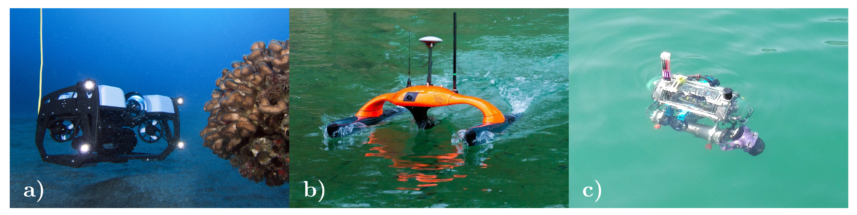
2.1. Remotely Operated Vehicles (ROVs)
ROVs are tethered to a ship or a generic external control station (see
Figure 1a). The tether streams data and images from the vehicle, allowing a human operator to real-time control the robot; therefore, the operator can organize data acquisition campaigns and close-up investigations in new and demanding environments [
16,
17,
18]. The tether generally also delivers power to the vehicle enabling long-time missions. However, it limits the ROVs working range, and it must be carefully and closely monitored to avoid bending, abrasion, or possible breakages. Teleoperation allows for the exploitation of all the human pilot’s creativity and dexterity and is currently preferred for delicate operations such as underwater manipulation.
As much as the use of this technology offers greater safety than recruiting technical underwater operators to explore particularly hazardous environments (e.g., underwater tunnels, harbour waters, or submerged infrastructures and cliffs), it still needs direct human intervention and, hence, is associated with an inevitable cost of personnel.
While ROVs can be deployed with proper precautions in shallow water (i.e., considering the presence of obstacles where the cable can get stuck, or identifying a proper area where the support vessel can navigate), their commonly generous dimensions make deep-water applications preferable. Finally, being underwater vehicles, their functioning is generally little impacted by waves and, therefore, their use (net of deployment) is poorly affected by the sea state.
2.2. Autonomous Surface Vehicles (ASVs)
ASVs represent a solution to replace fully-crewed ships to acquire data from the sea surface, e.g., bathymetric measurements, also over large areas (see
Figure 1b). Unlike AUVs, ASVs can rely on GPS measurements that increase the positioning accuracy, leading to a better quality of the bathymetric measurements. As discussed in [
19], ASVs are of great effectiveness in very shallow water areas that are inaccessible to AUVs, ROVs and commercial boats. The authors used an ASV to collect bathymetric data and reconstruct the sea-bottom of the Loano beach, Liguria, Italy.
Moreover, the study also highlighted the benefits of using robotics technologies by comparing the number of collected bathymetric samples with the available historical data. In addition, several other campaigns that exploited ASVs for collecting significant coastal management data are reported in the literature: e.g., in [
20], an ASV was used for acquiring bathymetric measures for risk assessment in shallow water environments and breaker zones; [
21] describes instead an automatic bathymetry sampling solution and an adaptive isobath environmental profiles tracking methodology for ASV surveys. In general, it is reasonable to state that surface navigation makes the use of ASVs the preferable solution for shallow water applications. ASV navigation is heavily affected by the sea state. For this reason, their applicability during or at the tail end of a storm is limited.
2.3. Autonomous Underwater Vehicles (AUVs)
AUVs are unmanned robots provided with their own power and control systems allowing them for highly independent mobility (see
Figure 1c). They usually conduct pre-programmed missions for a few hours up to several days, depending on the power systems and sensor set. When an accurate underwater navigation is needed, e.g., to georeference targets of interest, AUVs make use of Inertial Navigation Systems (INS) with Doppler Velocity Logs (DVL) and compasses in either Dead Reckoning (DR) navigation strategies [
22] or Bayesian estimators, such as Kalman Filters (KF) [
23].
Moreover, they can navigate close to the seabed and are, hence, capable of acquiring seafloor mapping, profiling and imaging data up to two orders of magnitude higher resolution compared to surface vehicles [
24,
25]. As a side note: AUVs can also be used as ASVs as they are usually equipped with GPS antenna and can thus be employed also in very shallow water; the vehicle stability on the surface is nonetheless reduced compared to ASVs due to the torpedo shape commonly adopted for the best underwater navigation.
Broadly, compared to ROVs, AUVs are more expensive due to the cost of the underwater sensors required for the navigation and localization algorithms, which have to guarantee high localization accuracy in a GPS-denied environment. Nevertheless, since AUVs can autonomously perform large-area mapping activities and underwater surveys without requiring continuous monitoring of an active operator, i.e., not requiring the support vessel to be located nearby, they significantly reduce the cost of the intervention and are suitable for frequent monitoring campaigns [
26]. Finally, AUVs can be deployed from shores or port’s quays, drastically reducing the campaign costs by skipping the ship’s logistic support.
Generally speaking, the robot’s size determines the maximum reachable depth, the minimum depth for operation, the sensor payloads it can carry and the mission time. Large dimensions usually are related to long autonomy, coverage of large areas, sophisticated payloads and great reachable depths. However, bulk vehicles have the non-negligible drawbacks of requiring a fully-crewed ship endowed with a crane for their deployment and high cost. Therefore, the purposes of marine-coastal environment monitoring may ask for more modular and compact robots [
26,
27,
28,
29] characterized by low logistic requirements and capable of performing frequent surveys in very shallow water [
30,
31].
As the name suggests, modular vehicles are composed of several modules each of which is usually dedicated to a specific task, allowing easy customization of the carried payload according to the mission to perform. The robot modularity also simplifies the logistic complexity since they can be carried dismantled and then assembled in situ.
The Gavia AUV
http://www.teledynemarine.com/gavia-auv (last accessed: 11 October 2021) represents a noteworthy example of commercial modular vehicles. It was specifically designed to reduce the logistic complexity and provide a self-contained modular platform for gathering high-quality data while operating from small vessels, port quays and shores. The Gavia AUV has a base configuration composed of four modules that can be extended with additional plug and play payloads modules. All modules are splash-proof and can be configured between the dives. Unfortunately, modularity also means several components (usually connectors) and design choices that make the vehicle forcibly cumbersome.
Compact robots, instead, which can hardly be modular due to the need for miniaturization and space optimization, are characterized by high maneuverability and limited weight and dimensions. Therefore, they offer reduced logistics but are much less flexible concerning changes in mission requirements—they are indeed usually provided with a semi-fixed core payload. On the upside, the small size allows their application not only in shallower waters but also in narrower spaces compared to modular robots.
In addition, as an average value, small and compact AUV can acquire reliable data up to 150 m deep, which makes this category of vehicles remarkably flexible in their field of application. As an example, FeelHippo AUV, described in detail in
Section 4, belongs to this class of vehicles. This small and lightweight vehicle can be easily carried around and requires a small crew to be handled. It can be deployed from a quay, a small boat, or even from the seashore, and its payload set can be extended in a limited amount.
The authors’ opinion is that, for recurrent monitoring campaigns in micro-tidal environments, modular and compact robots—ROVs, ASVs or AUVs—arise as strategic tools since they allow science-users to frequently investigate the ongoing processes without being affected by cumbersome logistic. The next section will dive deeper into the potential of marine robotics technology.
3. Marine Robotics Capabilities and Potential
Whether autonomous or remote-controlled, surface or deep-sea, large or small, all marine robots require a navigation system, mission planning strategies and a payload appropriate to the task they shall perform. All the above points will be here discussed in more detail. The purpose of this section is to highlight the capabilities of these systems and the different potentialities that this technology offers rather than to compare the different techniques since, as described, each one has its own peculiarities concerning specific applications.
3.1. Navigation Systems
As already mentioned, accurate navigation is not an issue for surface vehicles as they can reliably exploit the Global Navigation Satellite System (GNSS) signal for localization. When considering, instead, underwater vehicles, one of the most crucial aspects is represented by the navigation module intended as the real-time estimation of the vehicle’s position, orientation and velocity. Indeed, the GNSS signal is not an option in underwater environments because of the water’s well-known property of highly absorbing electromagnetic waves. The importance of this aspect goes beyond the capability of smoothly moving along the desired path: it also affects the capability of georeferencing the acquired data. The literature is dense with works on this topic [
22,
32].
A good knowledge of the dynamic model of the vehicle for predicting its motion is an aspect that cannot be underestimated. The data collected by all payload sensors can refine this prediction: the commonly adopted framework to fuse all the available information is based on Bayesian estimation that exploits the Kalman’s approach. Various techniques—ranging from the classical Extended Kalman Filter (EKF) to, e.g., the Unscented Kalman Filter (UKF) [
33] or the Particle Filter (PF) [
34]—can be implemented according to the degree of nonlinearity of the specific problem and the available computation resources. High-quality sensors, such as DVLs or high-grade Inertial Measurement Units (IMU), can guarantee low errors compared with the traveled distance (approximately 0.1%) and should be considered as essential payloads especially in long-term missions when periodical resurfacing to obtain GNSS signal is not possible or not energetically convenient.
In such cases, positioning systems based on acoustics are adopted to maintain low error values. According to the distance of the sensitive elements of the acoustic array, these systems are classified as Ultra-Short BaseLine (USBL), Short BaseLine (SBL), or Long BaseLine (LBL). In the multi-vehicle cooperation scenarios (i.e., more than one vehicle cooperating within a common mission) [
35], the acoustic devices in charge of the communication are also exploited as indirect observation of the navigation state with the swarm that acts as a mobile LBL system [
36,
37].
Another alternative or a complementary solution to acoustic positioning is “geophysical navigation”: all the techniques that use information collected from the environment fall under this classification. In this case, sensors capable of extracting environmental features (e.g., magnetic field, gravity field, bottom morphology) are necessary.
3.2. Mission Planning Strategies
Environmental monitoring missions carried out with autonomous vehicles—either ASVs or AUVs—usually cover broad geographical areas. Therefore, a specific path that minimizes costs while maximizing the explored area has to be carefully planned. In general, the primarily optimized aspects are related to safety conditions and the vehicle’s battery consumption. Therefore, the ideal situation is to follow routes that avoid obstacles or risky zones, covering the whole desired area while minimizing the traveling time and properly considering environmental conditions (e.g., flat and sloping areas for land operations or marine currents for marine exploration) to minimize energy consumption.
This requires implementing a good path planner that optimizes all the aspects mentioned above. The uniform environment to study the path-planning problem among static obstacles is called Configuration Space- in the literature. The main idea is to represent the vehicle as a point (i.e., a configuration). A vehicle configuration is a set of parameters that identify the vehicle position in the environment. The is the set of all possible configurations.
The set of regions free of static obstacles is called , while the set of areas containing obstacles is called . Coverage Path Planning (CPP) algorithms can be classified as offline or online depending on the environment’s a priori knowledge. Offline algorithms assume full prior knowledge of the environment, while online algorithms rely on real-time sensor measurements.
Usually, vehicles used for bottom morphology missions are equipped with acoustic sensors, such as Side Scan Sonar (SSS), Multi-Beam Echo Sounder (MBES) and Single-Beam Echo Sounder (SBES). The information provided by these kinds of sensors can be integrated into a path planning algorithm optimizing the path in real-time. There are two main philosophies for addressing the motion planning approach: combinatorial planning (the deterministic approach) and sampling-based planning (the probabilistic approach).
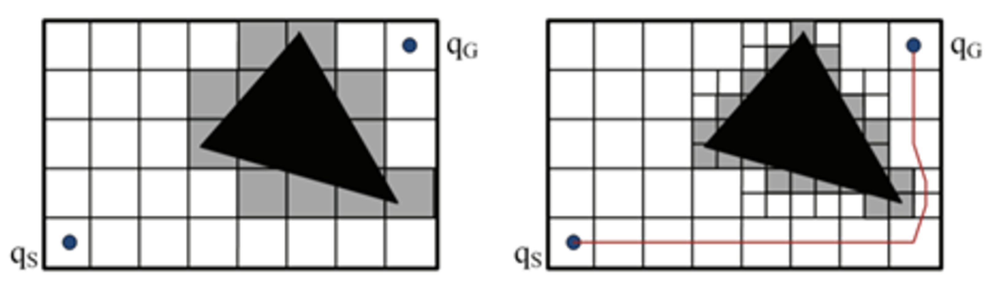
Combinatorial planning requires a priori knowledge of the environment. Therefore, it is used in environmental monitoring missions where the seabed morphology is well known, and the path can be computed without any sensor information. It requires an expensive computation of and ; however, since the path is calculated offline, it does not represent a bottleneck for this approach. The combinatorial planning implies a discretization of the free space and the generation of a topological graph on it. The most popular idea is to decompose the space into cells with predefined shapes so that any path inside a cell is obstacle-free.
The union of such obstacle-free cells is a lower approximation of the set
. The cell size determines the resolution of the algorithm and often constitutes a path optimization constraint.
Figure 2 shows the same scenario with two different cell sizes. The algorithms applied to combinatorial planning are based on graph inspection. The optimal path has to satisfy, in addition to resolution constraints, also vehicle motion constraints (kinematics and dynamics) and coverage constraints depending on the missions to be carried out. There is limited literature on deterministic path planning for autonomous vehicles: one of the first deterministic approaches for underwater path planning was presented by Carroll et al. in 1992 [
38], who proposed an underwater application of the A* path search algorithm. However, the results were strongly affected by marine currents; therefore, in [
39], Garau et al. proposed an adapted version of the A* algorithm that took currents into account.
Conversely, sampling-based planning does not require any a priori knowledge of the map. It is, in fact, used in exploratory surveys. A crucial property for any sampling-based planning algorithm is probabilistic completeness [
40]. This property has been proven for many path planning algorithms, including the Probabilistic RoadMap (PRM) [
41] and the Rapidly-exploring Random Tree (RRT) [
42].
The probabilistic approach in bottom morphology missions includes the modeling of the altitude in a stochastic process. The most commonly used stochastic process in the literature to model altitude is undoubtedly the Gaussian one, representing a powerful method to model spatial phenomena.
Figure 3 shows an example of a Gaussian process applied to the bathymetry study.
The probabilistic path planning aims to maximize the amount of information gathered. Therefore, the choice of an appropriate information metric plays a crucial role and in literature, many different metrics have been used for this purpose: Ruiz et al. in 2015 [
43] exploited the entropy as the reference metric, Levin et al. in 2010 [
44] used the Fisher information, while Julian et al. in 2014 [
45] applied the mutual information metric. A replanning phase is, therefore, essential to perform in order to update the stochastic process parameters with the information acquired during the mission.
3.3. Payloads
ROVs, ASVs and AUVs are all capable of carrying a wide variety of relevant sensor payloads. In [
46], an MBES was used to collect high-resolution data on the northern Ligurian margin, western Mediterranean. By exploiting underwater robots, the authors managed to collect data at a higher resolution than the MBES mounted on the surface ship; in fact, a ten-meter high fault scarp on the seafloor was imaged, and the field specialists were able to characterize the active tectonic and gravitational deformation. MBESs have been extensively used in the last few years for studying the seafloor morphology.
Such sensors allow mapping large areas in relatively short time periods. In addition, MBES capabilities extend beyond the acquisition of bathymetric data, and they can be employed for classifying the seabed sediments by investigating the sediment backscatter signal strength of the received echo. In fact, the backscatter strength depends on the seabed properties, such as the sediment bulk density, seafloor roughness, volume heterogeneity, discrete scatterers and sediment layering [
47].
Consequently, MBES data can also be used to monitor sediment distribution over large areas [
48]. Additionally, MBESs can play a key role in marine seep hunting: hydrocarbon seeps are small and difficult to sample but are instead evident in MBES measurements, making these acoustic devices an efficient tool to locate and map seep features [
49].
However, the underwater domain has several complex ongoing physical-chemical processes that need to be understood and several environmental variables that must be observed: MBESs are, then, used along with other sensors that provide environmental information, such as depth, temperature, salinity and optical images.
In [
50], the data collected by two robotic campaigns [
51,
52] were used along with multibeam bathymetry to investigate the distribution of the benthic communities of the Ningaloo Marine Park, Australia. In [
53], the authors equipped their robot with a mapping system composed of a MBES, a SSS and a Sub Bottom Profiler (SBP) to collect multi high-resolution data efficiently.
The system was employed in several seafloor observation campaigns along both the East and West North America coasts, which enabled the study of the bathymetric changes associated with sediment transport, seafloor morphology and benthic habitats, to mention a few. The same sensor payload set (MBES, SSS and SBP) was used in [
54] to map the Sigsbee Escarpment in the Gulf of Mexico.
Recent studies concerning the use of robotic vehicles in marine geoscience are not limited to mapping tasks. Indeed, in [
55] high-resolution photographic, bathymetric and sub-bottom data acquired from a robot were used to perform a seismo-acoustic characterization of the Green Canyon Lease Block 600, located in the Gulf of Mexico. The detailed seafloor maps and bathymetries were used to highlight numerous pockmarks, cones and micro-mounds of variable sizes and shapes. Seafloor sediment types were inferred by acoustic backscatter data. These data, combined with ground-truthing photo surveys, have also shown the presence of authigenic carbonate hardgrounds, gas hydrates and chemosynthetic communities.
Furthermore, marine robots are also being exploited to collect optical and acoustic imagery that can be analyzed by a human operator to monitor areas of interest and detect particular patterns that highlight the ongoing physical-chemical processes. Modern Automatic Target Recognition (ATR) strategies, based on Deep Neural Networks (DNN), applied to both optical and acoustic images [
56,
57,
58], represent a possible and promising solution to help (or even replace) human interventions in these particular tasks.
Finally, together with optical cameras, under good visibility conditions, Light Amplification by Stimulated Emission of Radiation (LASER) solutions can be found in [
59,
60,
61]. In [
59], a 3D LASER system was presented for middle-distance surveys of the seabed. The solution was validated during field tests, where the 3D seabed topography is obtained. In [
60], a 3D LASER system was reported for localization-aiding in a pose-based EKF Simultaneous Localization And Mapping (SLAM) framework. In particular, the feasibility of the LASER-based strategy to generate accurate point-cloud maps is demonstrated in real-time employing tank tests.
4. Test Case
This section provides the results of robotic experimentation campaigns carried out using FeelHippo AUV, the small underwater robot designed and built by the Department of Industrial Engineering at the University of Florence. Details of both FeelHippo’s characteristics and navigation strategy are reported in [
62], and a brief description of the vehicle is reported here. The data presented here are intended only to provide tangible examples of the information that can be gathered using a marine robot as a showcase of the potential described in
Section 3.
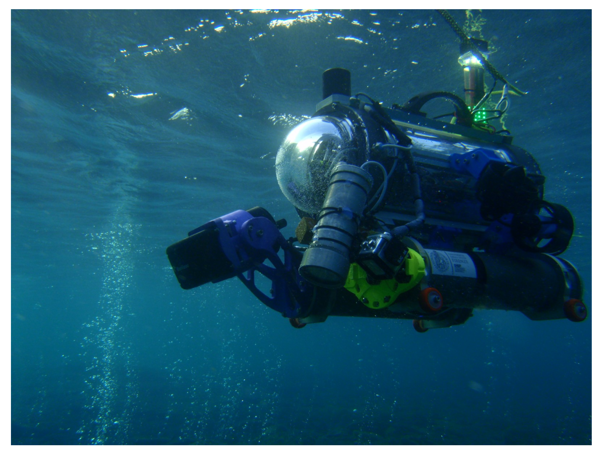
4.1. FeelHippo AUV
FeelHippo AUV (see
Figure 4) is composed of a central body made of a Polymethylmethacrylate (PMMA) hull and two aluminum pipes attached under the main body. The hardware and electronics are housed in the central body, while the lower aluminum pipes contain the batteries. Its dimensions (L × W × H) are 640 × 500 × 600 mm, it can reach a maximum depth of 30 m and has a total mass, a cruise longitudinal speed and power autonomy of 35 kg, 1 m/s and 3 h, respectively.
The propulsion is realized using six thrusters (two at the stern, two at the bow and one each on both sides inclined at 45° to the horizontal) arranged in a vectored configuration that allows for the control of all the Degrees Of Freedom (DOFs) of the vehicle, except for the pitch motion that depends entirely on the inner mass distribution and the configuration.
The control architecture is based on a main computer for onboard processing (Intel i-7-based LP-175-Commel motherboard) and on an additional payload as one NVIDIA Jetson Nano and two Intel Neural Compute Stick 2 for running onboard machine learning algorithms. In addition, it is equipped with the following sensors:
U-blox 7P precision Global Positioning System (GPS);
Orientus Advanced Navigation Attitude Heading Reference System (AHRS);
KVH DSP 1760 single-axis high precision Fiber Optic Gyroscope (FOG);
Nortek DVL1000 DVL, measuring linear velocity and acting as Depth Sensor (DS);
Teledyne BlueView M900 2D Forward Looking Sonar;
3 × Microsoft Lifecam Cinema cameras.
The first three sensors are used only for navigation purposes, while the others are proper payload.
4.2. Optical and Acoustic Monitoring: Mosaicking
Underwater mosaicking is a common topic in marine robotics. Relevant studies on this subject, which is fundamental to enhance the knowledge of underwater environments and a crucial tool for scientists, have been carried out by several researchers [
63,
64,
65,
66,
67]. This can be performed exploiting optical or acoustic sensors.
On the one hand, optical images (i.e., obtained from cameras) present high-resolution information provided at high refresh rates, but turbidity, intense light absorption and illumination effects can strongly influence the final results. On the other hand, acoustic images (i.e., obtained from acoustic payload as sonars) are characterized by lower resolution but, at the same time, are intrinsically more robust, being the acoustic sensors able to penetrate the water even in low visibility conditions and for longer ranges.
Information collected through mosaicking can be exploited to monitor interesting things from the coastal management point of view. Mosaics made by optical technology can be very useful to verify the status of underwater flora (e.g., Posidonia oceanica seagrass meadows) and, consequently, acquire information on water pollution. At the same time, optical mosaics can be used to check submerged defence structures. On the other hand, acoustic ones can provide valuable information about the littoral dynamics of longshore bars or enrich bathymetric maps with 2D/3D images of the seabed.
The test site was 130 m far from the coast. FeelHippo AUV was deployed from the pier of the basin by means of a small crane and navigated autonomously for a total time of almost 330 s covering roughly 120 m along a pre-programmed path covering an area of about 1100 m2 with an average depth of 10 m, while maintaining an elevation of 3 m above the seafloor.
During the exploration, FeelHippo updated/shared its estimated position and the mission status to the control station (on a small boat) using an acoustic modem. Eventually, specific emergency commands could have been sent to it to abort the mission.
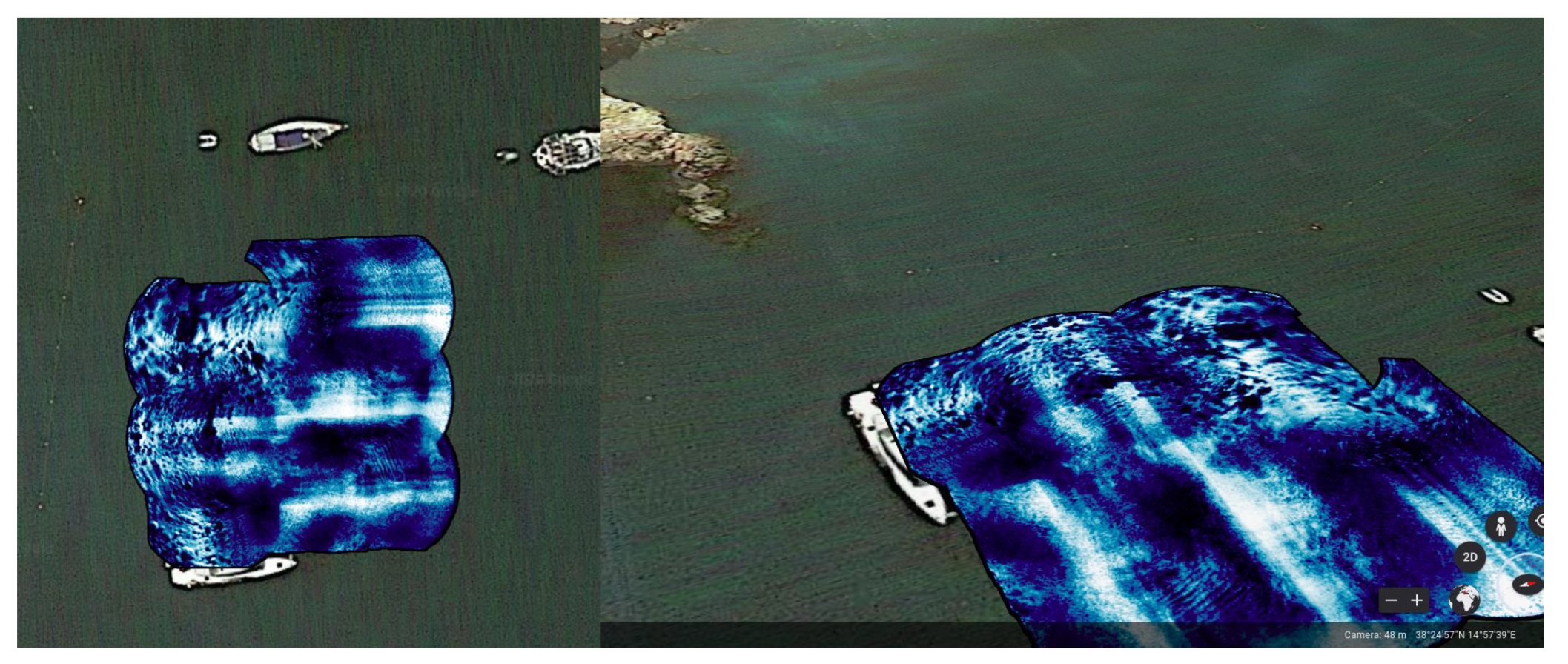
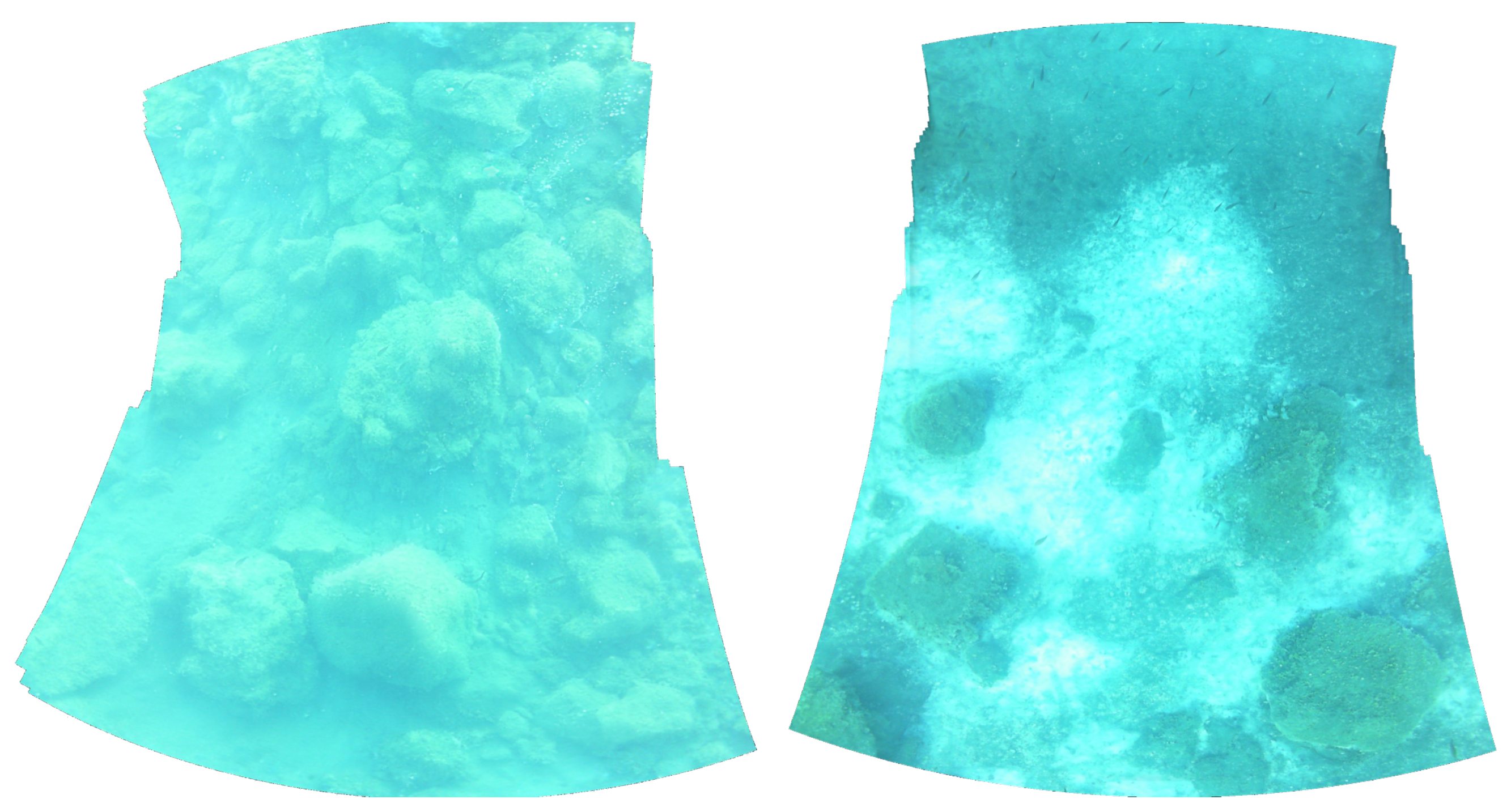
Right after the end of the autonomous mission, the acquired Forward Looking Sonar (FLS) images were processed on an i7-6700HQ laptop PC. The final results are depicted in
Figure 5 and
Figure 6. Important information on the seabed can be appreciated from both figures. In particular, the acoustic mosaics clearly highlight that the inspected underwater domain presents areas with different structural characteristics: the mosaic’s left portion covers a seabed disseminated with rocks of different shapes and dimensions while the right area showcases a flat seabed. The optical images give, instead, high-resolution information about the seabed and the status of the flora.
As already pointed out, the acquisition of high-quality optical data, as the two mosaics shown in
Figure 6, are strictly dependent on the sea conditions. The water clarity required to obtain such results is a characteristic that not all underwater environments possess. Therefore, it is necessary to ensure that the robot can acquire as much information as possible, even in low visibility conditions. Acoustic mosaic arises then as a noteworthy alternative in low-visibility scenarios.
4.3. Bathymetry
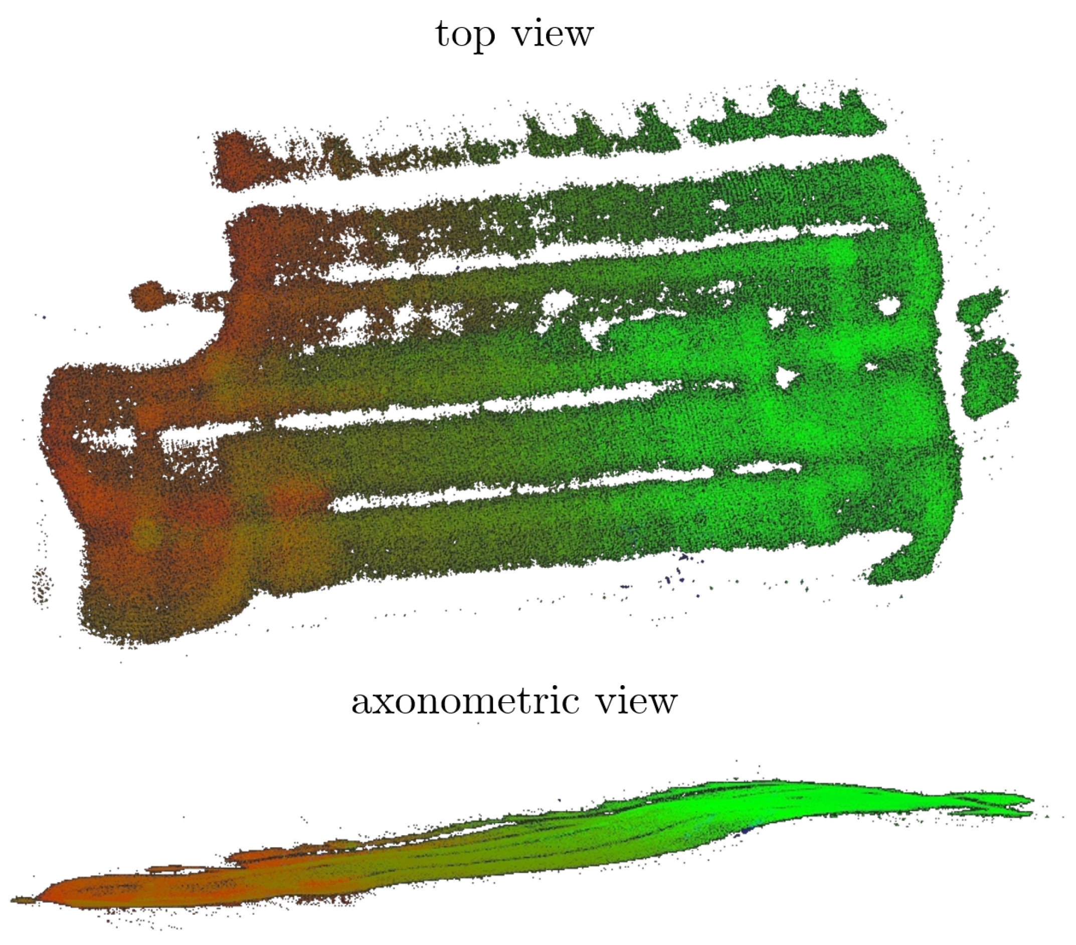
Bathymetric acquisitions, in addition to the already mentioned acoustic explorations, are an excellent example of data that can be acquired even when underwater visibility is not sufficient for the use of optical sensors. Another mission that can be mentioned is a test study that has taken place in La Spezia (Italy) in 2019, exploiting FeelHippo AUV equipped with the same instruments and payload configuration of the above mentioned mission. The results are presented in
Figure 7, where the sea bottom is roughly reconstructed by employing an altimeter and a FLS. Although the mission was carried out in a basin, and thus, in an all-too-controlled and regular environment, it is possible to appreciate the additional bathymetric information that can be gathered with these strategies.
The accuracy of the bathymetric acquisition depends on several factors, and an evaluation of the compounding accuracy has neither been undertaken theoretically nor experimentally. Certainly, among the factors mentioned above, the localization performance of the AUV, the accuracy of the sensing device and the reconstruction method, play a significant role. Concerning the localization accuracy, specific information is not available. However, without the employment of absolute positioning systems, while underwater, a suitable value (obtained from past underwater missions) is in the range of 1–3% of the length autonomously navigated.
With regard to the FLS accuracy, the device presents 768 beams with a beam spacing of 0.18° and a beam width of 20°. In addition to this, the range resolution is 1.3 cm. Last, concerning the reconstruction method, being the result of computer-vision algorithms, the accuracy evaluation is complex, and a thorough experimental campaign has not been performed yet. It is the authors’ opinion that, at 10 m altitude, the total accuracy is in the range of tens of centimeters.
4.4. Autonomous Coverage
Currently, the majority of AUVs do not employ exteroceptive sensor feedback to plan autonomous missions. However, water conditions and seafloor morphology definitely affect the performance of acoustic and optical payload. Indeed, to name an example, it is well known that FLS acquisition strongly depends on the presence of objects (especially tall objects) and the sea bottom characteristics. Therefore, AUVs that use perception-aware algorithms for planning can be a crucial tool for obtaining satisfying acquisitions during marine surveys.
In light of the reasoning, the authors developed an original AUV-based FLS-driven coverage framework to autonomously perform inspection surveys for area coverage [
68,
69]. Turning to technical details, a two-level planning paradigm was designed, where a high-level planner expands random trees considering the AUV kinematic constraints. The tree nodes are evaluated according to information gain metrics obtained from the occupancy map visibility and, working in a receding-horizon fashion, and only the first node is sent to an RRT-based motion planner.
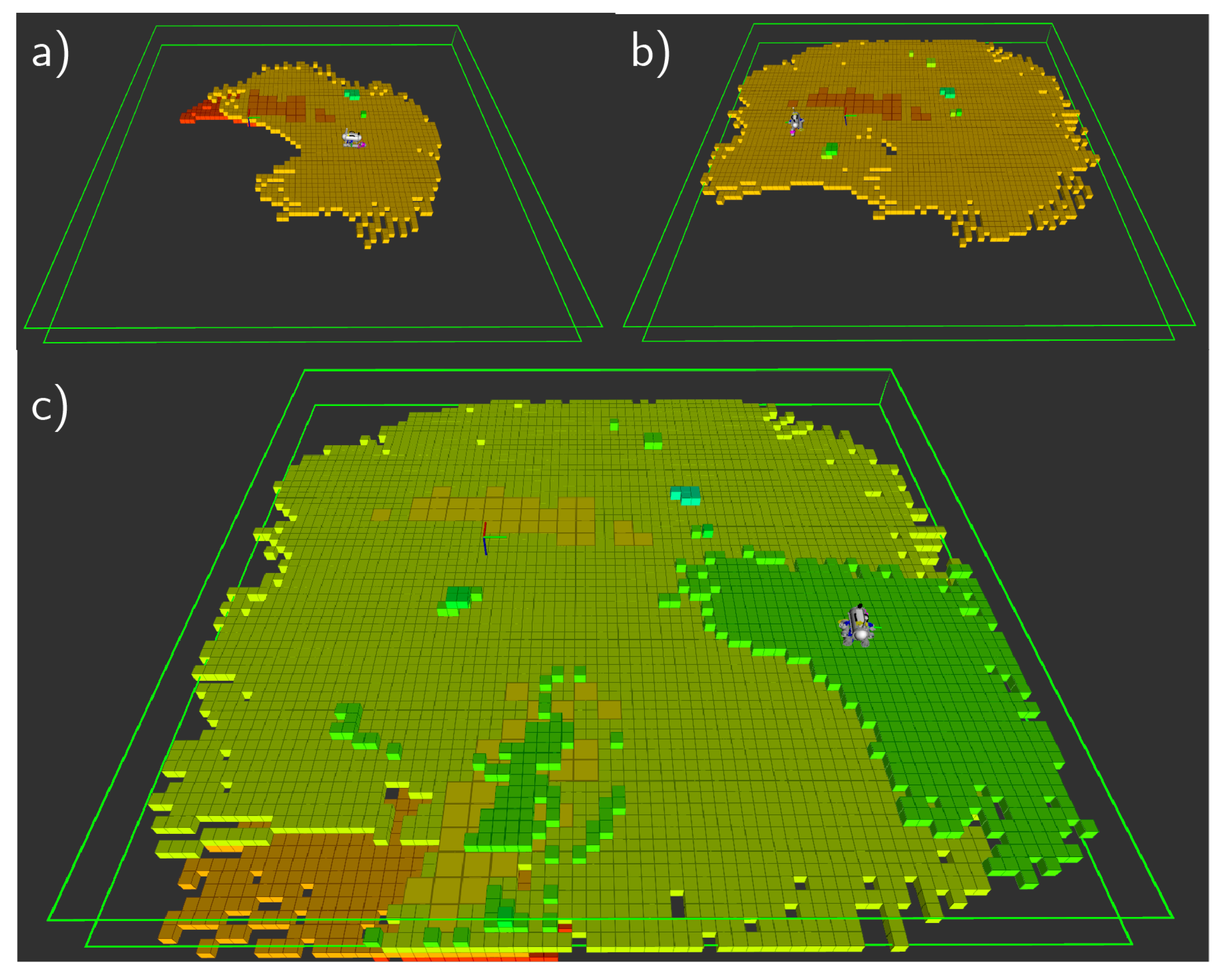
With regard to the environment representation, an occupancy grid map tailored to FLS observations is employed. In this context, FeelHippo AUV performed an underwater mission in La Spezia (Italy), on the 7 July 2021, within the EUMR project framework. The result of this test is visible in
Figure 8.
One of the main advantages of this technique is that, once the area to be covered has been defined, there is no need for further human intervention. This drastically reduces the need for on-site personnel during inspections and allows for easy and efficient scheduling of autonomous periodic monitoring of a given area of interest.
5. Discussion and Conclusions
A high number of processes affects the coastal zones. Therefore, monitoring is a vital and functional activity, which is often based on a time scale that is not compatible with some of the ongoing changes, failing to provide information that can effectively support decision-making. Such a wide time variability in coastal environments requires innovative solutions to be integrated with the current ones to fill this gap, especially when dealing with fast or recurrent surveys.
The promising field of marine robotics has been consolidating for years now and arises as a valuable ally for the management of coastal environments. A large numbers of different robots have been developed: some in prototype form and others already established as a commercial reality; they can move as teleoperated or autonomous vehicles, on the surface or underwater. The main differences as well as the strengths and weaknesses of each were described in
Section 2. Just as these robotic tools are diverse, so can be the applications they can be used for;
Section 3 gave an overview of their potential while
Section 4 showed some results that can be achieved by using this technology.
The use of these robotic vehicles for integrating the current strategies of coastal monitoring arises as particularly promising, especially when micro-tidal environments are considered. The features that make them complementary to standard techniques relate primarily to the intervention time, reduced need for personnel to supervise and investigable areas. These vehicles generally require little logistics and also short notice before field deployment.
This means that they can be used for both one-shot intensive surveys (e.g., right after an extreme event or a storm) and recurrent monitoring. In addition to being powered by Artificial-Intelligence-based algorithms, such robots can navigate, collect data, and make decisions autonomously. It follows that the little human intervention usually required to manage them, would, in fact, dramatically reduces the personnel costs required to operate them. Finally, the small size and the high maneuverability of some of the available vehicles will allow them to explore areas unreachable by standard vessels or too risky for operators.
The potential of marine robotics is not limited to the acquisition of data but, rather, is fulfilled in the rational and analytical exploitation of the enormous amount of information they make available. Indeed, such new information will offer the opportunity for enhancing and renewing modeling chains from ocean to coastal scales and also enriching sharing framework, as the Copernicus Marine Environment Monitoring Service (CMEMS), with new products and services. Exploiting data representative of high-resolution and high-dynamics phenomena will provide effective solutions for coastal areas that are key for significant human activities (in order to pursue the challenges targeted by the Horizon Europe Mission: “Healthy oceans, seas, coastal and inland waters”). This, reasonably, will be an important development point for the foreseeable future.
The last point of interest concerns marine robotics regulations. Unlike its aerial counterpart (i.e., aerial drones), the use of autonomous marine robots is not currently under such tight regulation. The authors believe that one of the main reasons for this delay may be undoubtedly the limited exploitation of this technology, which is more expensive and complex than aerial robots. However, it is reasonable to expect a rapid change in the coming years regarding the laws governing marine robot use.
In addition to the “standard” hazards (e.g., bathing hazards, collision with other vessels, the release of pollutant material, and the disturbance of underwater fauna and flora), the growing autonomy of these devices raises new questions about civil and criminal liability in the event of an accident. Therefore, the authors expect that the scientific debate on these issues will soon cause precise and timely regulations on the use of marine robotics to arise.


 ,
, 
