1. Introduction
Accurate physical modelling requires in many cases to deal in a proper way with wave reflections from models or boundaries in the model testing facility. Reflected waves in wave flumes and basins will, without active absorption, be re-reflected at the wavemaker and become incident waves. The purpose of the active absorption system is to generate an opposite wave to the re-reflected one so that the two will cancel each other out.
In wave flumes, a single paddle is usually used for wavemaking, and reflected waves are usually unidirectional. Thus, active absorption systems usually assume reflected waves to be head-on to the wavemaker. Examples of such systems are Milgram [
1,
2], Schäffer et al. [
3], and Lykke Andersen et al. [
4,
5] for nearfield surface elevation feedback, Frigaard and Christensen [
6] and Hald and Frigaard [
7] for farfield surface elevation and/or particle velocity feedback, and Salter [
8], Chatry et al. [
9] and Spinneken and Swan [
10] for force feedback.
Even though waves in such systems are assumed to be head-on to the wavemaker, these systems are widely used in wave basins. In such cases, a number of 2-D systems are used in parallel to form a pseudo-3D system, whereby the wave direction is not taken into account, and thus, performance decreases with increasing obliqueness of the waves to be absorbed. To perfectly absorb an oblique wave, a reduced wavemaker stroke will be required, and the phase must also be slightly different. For this reason, pseudo-3D systems overreact when absorbing oblique waves, cf. Schäffer and Klopman [
11].
The system by Schäffer et al. [
3] was extended to a full-3D system by Schäffer [
12], in which the wave direction is taken into account by including neighboring wave paddles. The Schäffer [
12] system was validated in a numerical wave basin by Schäffer and Skourup [
13]. The transfer function used for the full-3D system [
12] is based on linear wavemaker theory for fully dispersive waves including evanescent modes (fully linear wavemaker theory). Evanescent modes are standing waves in the nearfield caused by not generating the correct vertical velocity distribution, e.g., when using a piston wavemaker to generate a deep water wave. However, Schäffer did not take into account the spurious waves generated by the wrong longitudinal velocity distribution, which occurs due to the segmentation of the wavemaker (i.e., insufficient discretization of the wavemaker). As demonstrated by Sand [
14] and also by Schäffer [
15], these spurious waves might be standing waves in the nearfield, but they might also be free propagating waves with a different direction to the target free wave. Inherently Schäffer [
12] thus assumed an infinitely small segment width. Schäffer and Skourup [
16] mention this limitation, but its consequences were not discussed.
In the present study, the consequence of spurious waves on the performance of active absorption systems is studied. First, the mathematical model for the nearfield surface elevation without and with spurious waves is presented. Then, the equations for the theoretical absorption performance are introduced, with and without spurious waves included. Based on the developed equations, the influence of paddle discretization on the theoretical performance curve for oblique waves is quantified for typical configurations of shallow water wave basins. Finally, the consequences of the obtained results with respect to the performance and stability of active absorption systems are discussed.
2. Nearfield Surface Elevations for Infinitely Narrow Paddles
The surface elevation in the nearfield may be calculated from the Biésel far- and near-field transfer functions, cf. Biésel and Suquet [
17]. The nearfield disturbance appears because the vertical velocity profile generated by the wavemaker deviates from the one in the farfield. In the present section, we only consider a linear wave generated by infinitely narrow paddles; thus, spurious waves which occur due to the segmentation of the wavemaker are not considered. Assuming the wavemaker is located along the
y-axis, then Equation (2) defines the motion needed to generate a linear regular wave with the farfield surface profile given by Equation (1).
where ω is the cyclic frequency. The displacement amplitude at the still water level (
z = 0) is
e0 =
0.5H/C0,3D, where
C0,3D is the farfield Biésel transfer constant for oblique waves, cf. Equation (5).
f(
z) describes the vertical variation of the paddle displacement and is unity for piston wavemakers, while expressions for other wavemaker types are given in Lykke Andersen and Frigaard [
17]. The distance between two crests along the wavemaker (
y-axis) is
Ly = 2π/
ky =
L/sin θ, where
L is the wavelength. Thus,
k = [
kx,
ky] =
k[cos θ, sin θ] is the wave number vector for the progressive wave. The wave number (
k) is the real solution to the linear dispersion relation:
where
g is the gravity acceleration and
h is the water depth. In Equation (3), the surface tension and nonlinearity effects are ignored. Surface tension is important for very short waves (capillary waves), but for the frequencies examined in the present paper (0–4 Hz), the influence of surface tension on the wavelength is 3% at most. For frequencies that show the most interesting results (up to 2.5 Hz), the effect is less than 0.5% on the wavelength, and is thus, negligible. Nonlinear effects might be more important. The phenomena studied later in the paper are mainly related to the wavelength. As both amplitude dispersion and surface tension effects result in waves which are longer than those given by Equation (3), some of the observed phenomena might occur at slightly higher frequencies than what is given by the results of the present paper.
The surface elevation (
η), including the nearfield disturbance generated by the displacement in Equation (2), may be calculated using linear wavemaker theory in a given coordinate (
x,
y) as a function of time (
t) according to Lykke Andersen and Frigaard [
18]:
where
Cj,3D are the Biésel transfer constants which, for
j = 0, is the farfield transfer constant and for
j>0 is the nearfield transfer constants (evanescent waves). The far- and near-field transfer constants for oblique waves are related to those for head-on waves through:
The constants
Cj,2D depend on the wavemaker type and are given in Biésel and Suquet [
17]. For a piston wavemaker, we have:
The wave numbers
kj for the evanescent waves (
j>0) might be calculated as the positive solutions to:
Equation (4) may be written as:
where the nearfield Biésel transfer function is given by:
These equations are used to generate linear regular waves. Linear irregular waves are produced by generating a number of regular wave components at various frequencies and in various directions. Thus, by applying above theory for each component, irregular waves may be generated.
3. Spurious Waves
To generate waves obliquely to a wavemaker, a segmented wavemaker is needed. Due to the inability of the segmented front of the wavemaker to form the sinusoid given by Equation (2), so-called spurious waves are generated. Spurious waves are caused by the generated velocity variation along the wavemaker being different from the theoretical profile of the target farfield wave. The nearfield disturbance presented in
Section 2 is due to vertical variations in the velocity being different from the target. Thus, spurious waves have a similar origin to the nearfield disturbances described in
Section 2, but are caused by the wrong longitudinal distribution, as opposed to the vertical one. The wrong vertical distribution causes only a nearfield disturbance (evanescent modes), whereas the wrong longitudinal distribution may lead to both evanescent and progressive waves. If progressive spurious waves occur, they will propagate into the model area.
Spurious waves were dealt with theoretically by Sand [
14] and Schäffer [
15], who showed that their relevance depends on the wavelength (
L), wave direction (
θ), segment width (
lp) as well as on the discretization type. Typically, stepwise linear (vertical hinged) or stepwise constant (box-mode) segmented wavemakers are used (see
Figure 1).
In both cases, the paddle shape deviates from the target sinusoid described by Equation (2) and spurious waves are generated. For identical segment width (lp), the piecewise linear discretization is a much better approximation of the theoretical sinusoid. For this reason, the spurious waves are also much smaller for this segmentation than for box-mode paddles. Box-mode wavemakers are more common due to their simpler mechanical arrangement.
In order to study the influence of spurious waves on active absorption systems, it is necessary to establish a mathematical model for the surface elevation in the nearfield including spurious waves. For this purpose, we use the method outlined by Sand [
14] and Schäffer [
15] for infinitely long segmented wavemakers. It is desirable to work with complex notation, with
being the imaginary unit number.
In the actuator positions
ym, the motions perfectly follow Equation (2); using complex notation, we have:
where
ym =
mlp with
m being an integer. Between the actuator positions, the paddle positions may be written as:
where ξ(
y) is dependent on the discretization type. At the actuator positions, we have in accordance with Equation (12) that ξ(
ym) = exp(-
ikyym). For box-mode paddles, we have a piecewise constant function where the paddle position for each board is equal to the position at the actuator, and is thus given by Equation (14). For vertical hinged paddles, the displacement is a piecewise linear function between two actuators, as given by Equation (15).
Sand [
14] and Schäffer [
15] expanded ξ(
y) in a Fourier series, and after quite some algebra, they found:
where:
p = 0 corresponds to the desired motion that occurs for infinitely narrow paddles.
p ≠ 0 is the unwanted spurious modes that occur due to the discretization. Thus, the ideal sine shape given by Equations (2) and (12) only occurs if
a0 = 1 and
ap = 0 for
p ≠ 0. The variation of |
ap| with
lp/
Ly is shown in
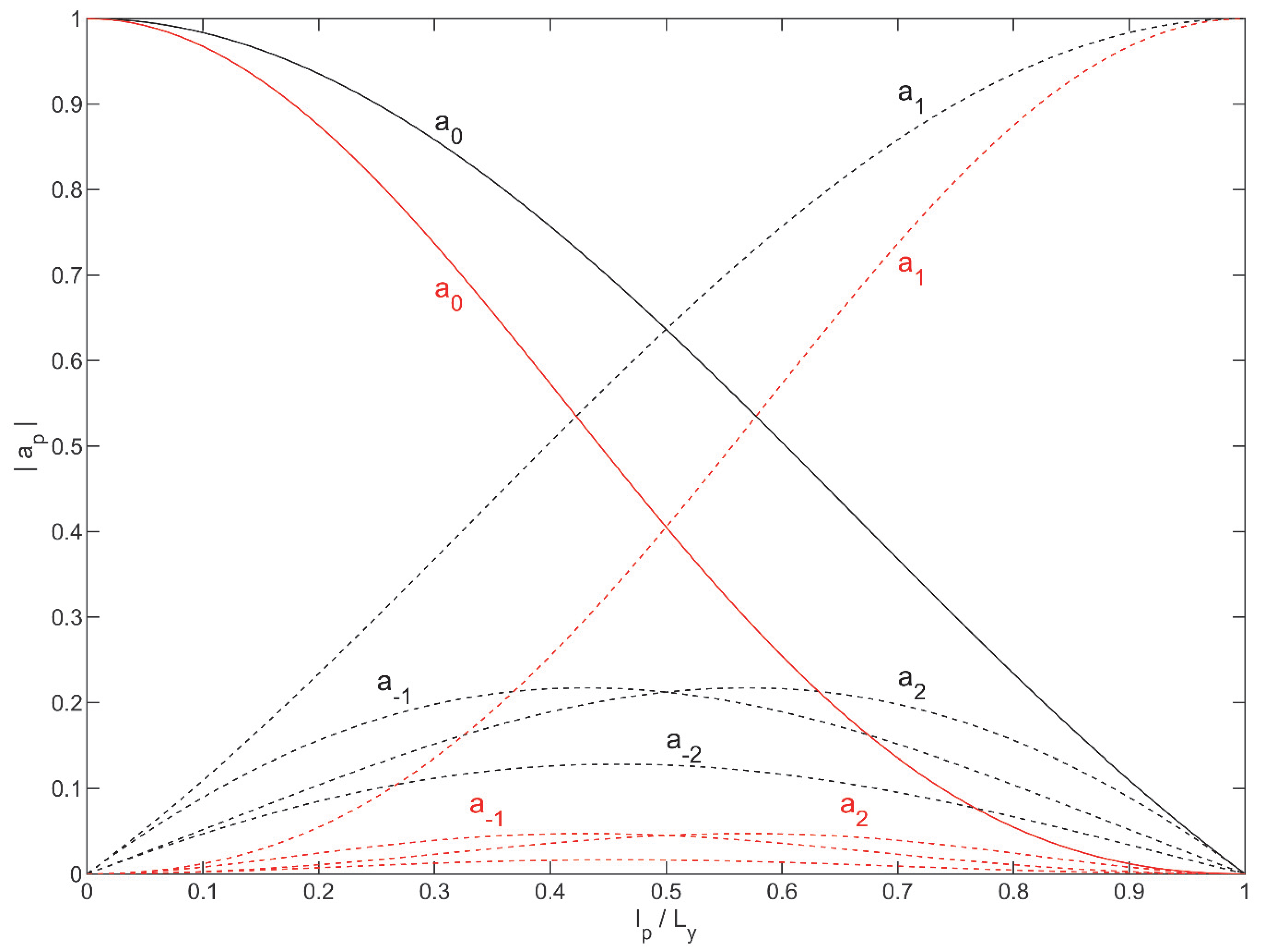
Figure 2 for the two discretization types.
It is demonstrated by
Figure 2, that by increasing
lp/
Ly, the amplitude of the desired motion (
a0) decreases, and the amplitude of the spurious components increases. At small values of
lp/
Ly, the amplitudes of the spurious modes vanish for vertical hinged systems while they grow linearly with
lp/
Ly for box-mode systems. At
lp/
Ly = 0.5 (the Nyquist limit), the amplitude of the first spurious component (
p = 1) is the same as the amplitude of the desired motion, independent of the discretization type. The amplitude of the other spurious components is at the Nyquist frequency though much higher for box-mode than for vertical hinged systems. At
lp/
Ly = 1, all paddles move in phase and only head-on waves are generated; thus, no energy is introduced in the desired motion (only spurious waves generated). The overall conclusion is that vertical hinged paddles have much less spurious energy than box-mode systems.
It is also interesting to note that the decrease of |
a0| with
lp/
Ly is stronger for vertical hinged systems than for box-mode systems. This is because for vertical hinged systems, less energy is introduced, as is also shown in
Figure 1. In wave generation, this can be compensated for, so the desired progressive wave has the desired amplitude. The decrease in
a0 will also affect the active absorption of oblique waves, as will be shown later.
4. Nearfield Surface Elevations Including Spurious Waves
The nearfield surface elevation caused by the motion given by Equations (13)–(20) may be calculated using linear wavemaker theory for each mode (
p) in Equation (16). In order to make a comparison with Equation (10), it is written in real notation, yielding:
where the first term is progressive waves (the desired one for
p = 0 and otherwise spurious). Progressive spurious waves exist when γ = 0 and p ≠ 0, where γ is defined as:
The second term in Equation (21) is evanescent spurious waves and the last term is the evanescent modes due to the incorrect vertical velocity profile, as described in
Section 2 (for each of the
p modes). The following definitions are used in Equation (21):
For active absorption, it is only necessary to evaluate Equation (21) at the gauge positions, which means usually only at
y =
ym, and thus:
The last term is a multiple of 2π, and thus,
inside the sines and cosines can be replaced by
. The extension of Equation (21) to irregular and short-crested waves is obtained by applying Equation (21) to each individual component, as discussed in
Section 2.
5. Nearfield Active Absorption Theory
In the present section, the target transfer function for perfect absorption of oblique waves for infinitely narrow paddle will be given first. This is based on fully linear wavemaker theory, including evanescent modes, as also used by Schäffer [
12]. Compared to Schäffer [
12], however, the present transfer function is extended to also cover cases where the wave gauge is mounted with a small gap to the paddle face, as also done by Lykke Andersen et al. [
5] for head-on waves.
Afterwards, the filter design method is outlined, followed by the method to calculate the theoretical re-reflection coefficient of the paddle as a function of frequency and direction for the designed filter. Compared to previous studies, these formulae will be extended to include the spurious waves based on the mathematical description given in
Section 4.
5.1. Active Absorption Theory
From Equations (2) and (10), it can be seen that the following relation applies in Fourier space in case of no reflection:
where
Xgen is the paddle position at
z = 0.
AWG,Gen is the surface elevation in Fourier space measured by the wave gauge (WG) located at (
x,
y) = (
dWG,
ym), i.e., with a gap
dWG between the paddle and the wave gauge. Using this equation, it is possible to calculate the expected surface elevation at the wave gauge without reflections and active absorption.
In the present paper, a dual mode active absorption system is considered, so the generation and absorption loops are separated. Thus, the generation may be nonlinear, and only the absorption correction is based on linear wavemaker theory, as given in Equations (27)–(28). Thus, the active absorption will only react to the difference between the measured surface elevation and that which occurs due to the generated incident waves that may be calculated with nonlinear theory. In Fourier space we have:
A reflected wave with a complex amplitude at the paddle
AR and a re-reflected with complex amplitude
ARR is now included; paddle displacement correction (
XAbs), that these conditions lead to, is also included. When components due to
XGen are removed, this gives a surface elevation at the wave gauge:
Assuming 100% reflection at the paddle, then
ARR =
AR, and thus:
The incident farfield waves at the paddle (
AI) include the farfield components generated due to the paddle motion and the re-reflections at the paddle (
ARR =
AR). Due to dual mode system, only the generated waves due to active absorption correction should be included:
Isolating
AR and inserting it into Equation (31) after setting
AI,Abs = 0 for perfect active absorption gives:
Thus, the theoretical transfer function as a function of frequency and wave direction has been derived.
5.2. Realtime Realisation
In order to apply the transfer function in a real time system, a causal filter (digital or analogue) is needed. Due to the causality requirement of the system, the filter design is far from trivial, and only suboptimal filters may be designed. Thus, the real filter response
will be different from the target
H(
f,θ). The dependency of the wave direction may be included by using a 2-D filter for each paddle, as used by Schäffer [
12], i.e., the response of the considered paddle depends also on the surface elevations measured on one or more neighboring paddles.
In the present case, a pseudo-3D system is used, and thus, a 1-D filter is applied for each paddle. The filter response is thus independent of θ, and the filter response is given by
. Lykke Andersen et al. [
5] showed that with an iterative procedure, it is possible to develop a FIR filter with slightly better performance for head-on waves than the IIR filter developed by Schäffer [
12]. By using a FIR filter, error accumulation in the filter is avoided. Examples of filter designs and related performances were presented by Lykke Andersen et al. [
5] for head-on waves. In the following subsection, it will be shown how the performance is calculated for oblique waves.
5.3. Theoretical Performance Curve
When a causal filter has been designed with frequency response function , the theoretical re-reflection coefficient of the paddle can be calculated based on linear wavemaker theory. In the present and following subsections, the method will be outlined both when spurious waves are excluded and included.
The active absorption paddle correction signal
from
is found by inserting Equation (31) into Equation (33):
which can be rearranged into:
The re-reflection coefficient of the paddle is defined as the re-reflected amplitude divided by the amplitude of the wave to be absorbed (the reflected wave). The re-reflected amplitude is the sum of the generated incident waves from the absorption correction
and
ARR =
AR. For infinitely narrow paddles, the re-reflected amplitude becomes:
By including
from Equation (36) and rewriting, the following is found:
where the right hand side is the performance parameter λ(
f,θ). Thus, we get the following equation to calculate the reflection coefficient:
The re-reflection coefficient can thus be calculated by Equation (39), where for infinitely narrow paddles, the performance parameter λ is calculated from:
5.4. Theoretical Performance Curve Including Spurious Waves
For finite paddle segment width, spurious waves occur, causing two changes to the equation presented above. The function α that relates the paddle displacement to the nearfield surface elevation (see Equation (27)) is changed in accordance with Equation (21). This is the only change in the function of
in Equation (36). Furthermore, Equation (37) is changed, as it is seen that the incident waves due to absorption correction in the direction of the re-reflected waves are found for
p = 0 only. Thus, Equation (37) becomes:
The paddle re-reflection coefficient can thus be calculated from Equation (39) for
p = 0 using the following parameters:
The above relation for α is determined using Equation (21), remembering that Equation (26) applies for the wave gauge positions assuming gauges located at y = ym.
5.5. Reflections in Other Directions Due to Spurious Waves
Above, we only considered the direction of the re-reflected waves, but the absorption correction might lead to unwanted waves in other directions being generated due to spurious waves being generated during the absorption of the reflected waves. The spurious waves are progressive for
. As shown in
Figure 2, the spurious waves might be high, and thus it cannot be ruled out that re-reflections in other directions may be higher than in the direction of the re-reflected wave. Waves in other directions occur for
p≠0 when the
p value corresponds to a progressive wave. In that case, they lead to an additional re-reflection being generated with amplitude:
The re-reflection caused in other directions (
p ≠ 0) is found by inserting
from Equation (36) into the above, which gives:
where α is given by Equation (44). Thus, both the reflection in the direction of the re-reflected wave and in the direction of the progressive spurious waves are studied in the following section.
6. Results
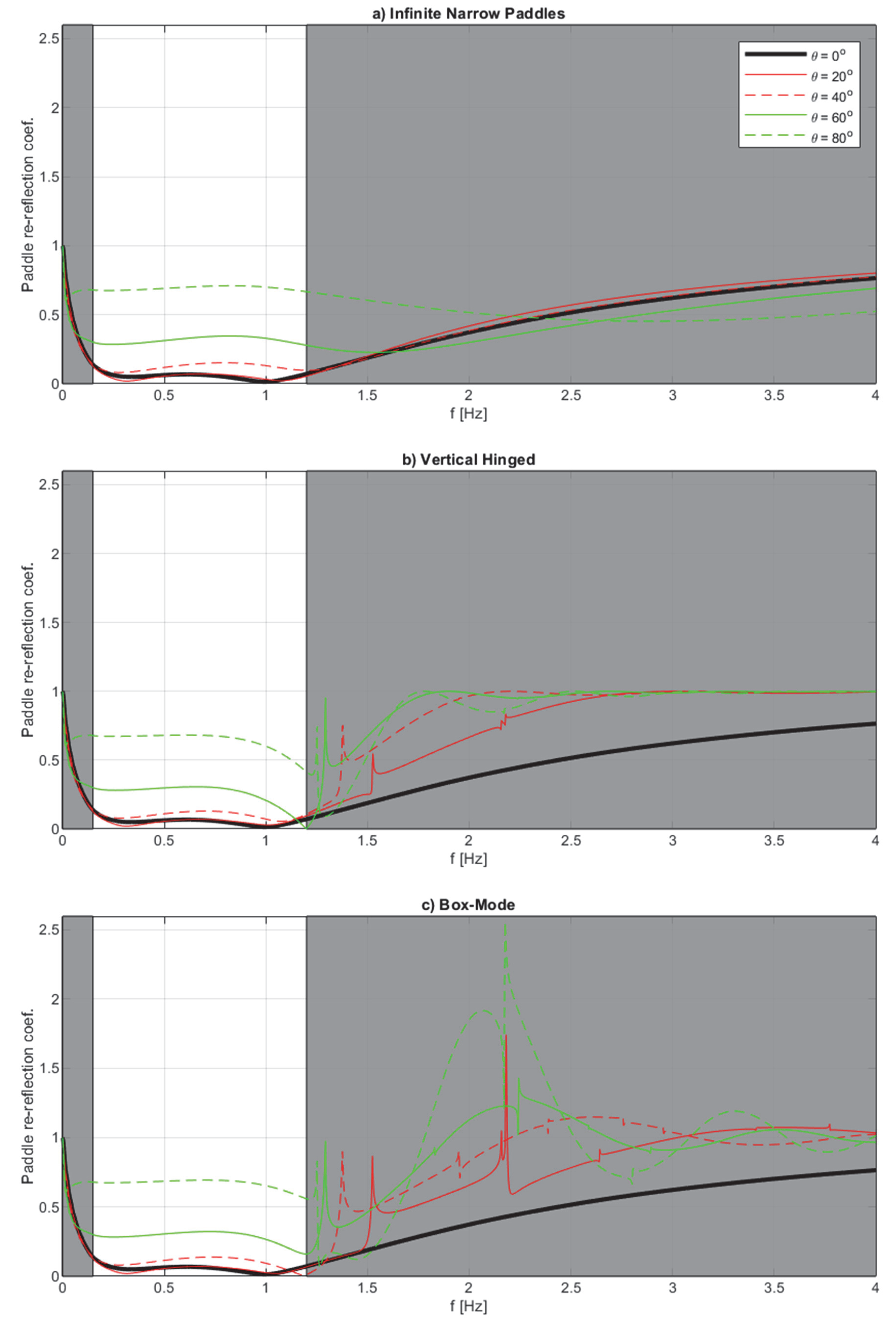
In order to demonstrate the influence of the spurious waves on the performance and stability of the pseudo-3D active absorption system, a typical shallow water basin with water depth h = 0.65 m is considered. Such a basin typically uses a segmented piston wavemaker with a segment width of around half a meter; for this reason, we consider piston wavemakers with lp = 0.5 m. The control delay used is 40 ms, which is a typical value for control systems with low delay (VTI for example). As the control delay is low, the wave gauge can be flush mounted (dwg = 0) with good absorption performance for head-on waves. Lykke Andersen et al. (2016) demonstrated less than 10% reflection in a wide frequency range. The frequency band in which the system performance is optimized is, in the present case, from 0.15 Hz to 1.2 Hz. The filter has 3281 filter coefficients at a 50 Hz sample frequency, corresponding to a duration of around 65 s. The long filter length makes it possible to absorb long waves with a FIR filter.
6.1. Re-Reflection Coefficient in the Direction of the Re-Reflected Wave (p = 0)
Using Equation (39), the theoretical performance curves for the re-reflection in the direction of the re-reflected wave are calculated and given in
Figure 3 for the case with
dwg = 0. Performance curves are given for infinitely narrow paddles (Equations (39)–(41)), as well as vertical hinged and box-mode segmented wavemakers (Equations (39), (43), and (44)). It appears that from 1.25 Hz and beyond, there are peaks and jumps in the paddle re-reflection coefficients caused by spurious waves. A closer examination reveals that the jumps occur when the spurious wave components change from being evanescent (γ = 1) to progressive (γ = 0). This transition occurs for a given mode (
p) of the spurious waves when |
kyp| =
k.
Table 1 shows the frequencies where this is fulfilled for various values of
p for the present case (i.e.,
lp = 0.5 m and
h = 0.65 m) and the directions considered in
Figure 3.
It is also clear from
Figure 3 that box-mode paddles might have significant stability issues as the paddle re-reflection coefficient exceeds unity significantly for highly oblique waves and peaks at
Cr = 2.5 at
f = 2.2 Hz. Both the vertical hinged system and the infinitely narrow paddles have re-reflection coefficients which are below unity at every frequency and wave direction combination. This reveals the importance of considering spurious waves in stability assessments of active absorption systems with box-mode paddles.
One might think that stability issues can be avoided by only introducing energy at frequencies below the limit where stability issues can occur. However, this does not solve the problem, as energy at higher frequencies is generated in the model area due to wave nonlinearities, wave-structure interactions, and wave breaking. Also, electrical noise in the signals might occur at the problematic frequencies. In both cases, the result is the introduction of energy at the problematic frequencies that might grow over time, and might even lead to an unstable system. It should be noted that most control systems (e.g., PID controllers) attenuate higher frequencies to some extent, and thus, reduce somewhat the stability issues presented in
Figure 3. With respect to the performance inside the operational frequency band, it can be seen that from 0.8–1.2 Hz, the performance of the vertical hinged system is notably better than for infinitely narrow paddles. For box-mode paddles, the same effect is observed, but to lesser degree. This directional dependency for segmented wavemakers is caused by the generated amplitude of the target wave (
p = 0) is decreasing when
lp/
Ly increases (see
Figure 2). For this reason, the effect is most pronounced at higher frequencies (low values of
Ly). For vertical hinged system, the effect is more pronounced than for box-mode systems (see variation of
a0 in
Figure 2). For this reason, there is some directional dependency, even in a pseudo-3D system, but it is only significant in a small part of the operational frequency band.
It appears that even though only pseudo-3D systems are used, the performance is excellent up to 40 degree obliquity with less than 13% reflection in the tuned frequency range from 0.15 to 1.2 Hz. For 60 degree obliquity, the reflection shows a maximum of around 30% re-reflection in the same band.
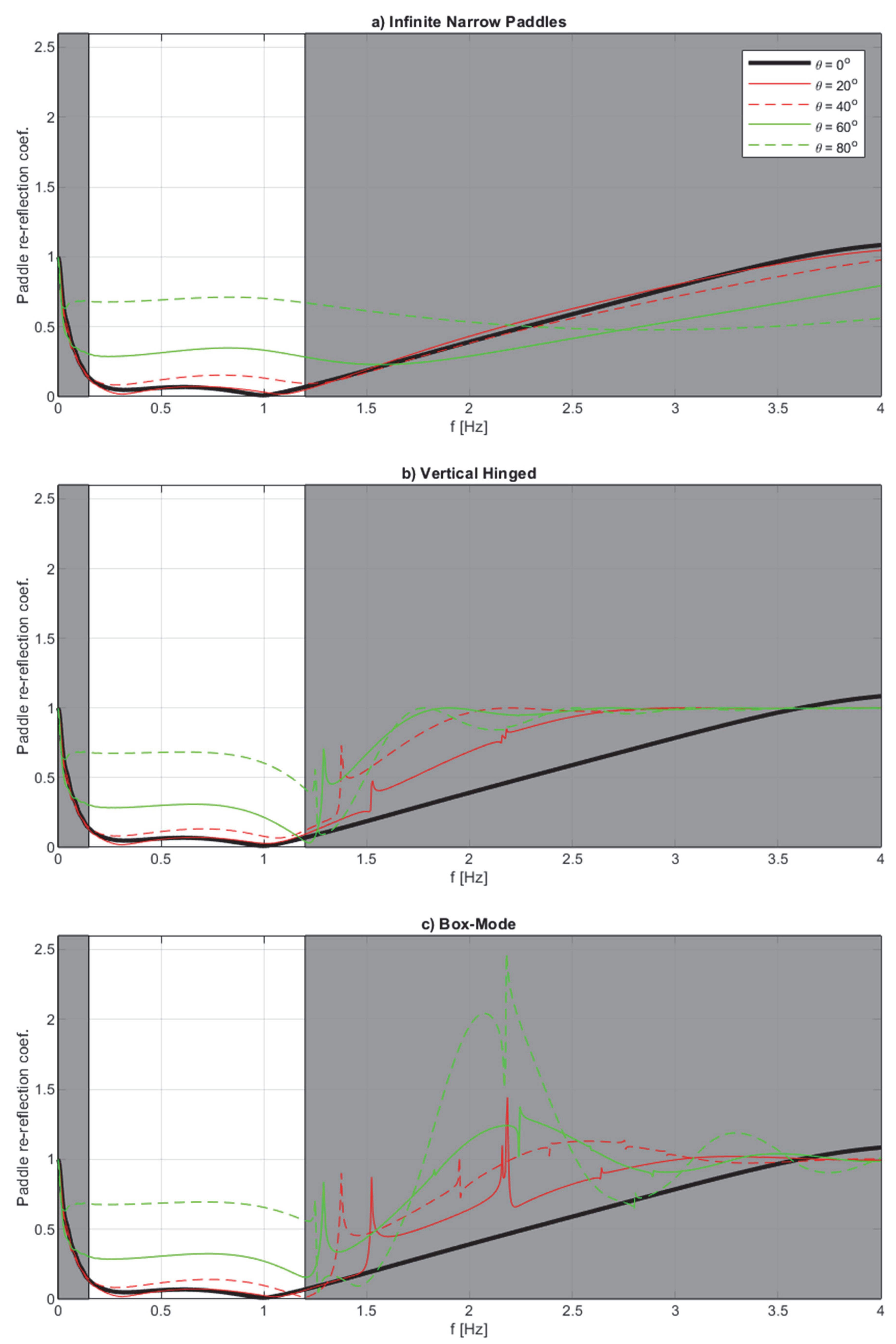
Vertical hinged paddles with flushed mounted gauges (
dWG = 0) are mechanically difficult to manufacture, as it is assumed that the gauges will be mounted in front of the hinge (
y =
ym). In practice, a small gap is needed, and we thus also consider a case with
dwg = 3 cm, with the remaining parameters being identical. As the transfer function is different, the filter is also recalculated. The results for this configuration are shown in
Figure 4. In this case, the theoretical phase at higher frequencies has jumps which make it difficult to avoid paddle re-reflection coefficients above 1.0 for head-on waves at every frequency. In the present example, the maximum re-reflection coefficient appears at 4.3 Hz with a re-reflection coefficient
Cr = 1.10. This small exceedance of unity has, however, not posed any stability issues, even for control systems that do not attenuate higher frequencies. Otherwise, the small gap (
dWG = 3 cm) has only minor influence on the obtained results for both box-mode and vertical hinged systems. Nevertheless, it is worth restating that Lykke Andersen et al. [
5] showed that a small gap may be used to improve performance in cases where the control system has a larger delay (i.e., above 80–100 ms).
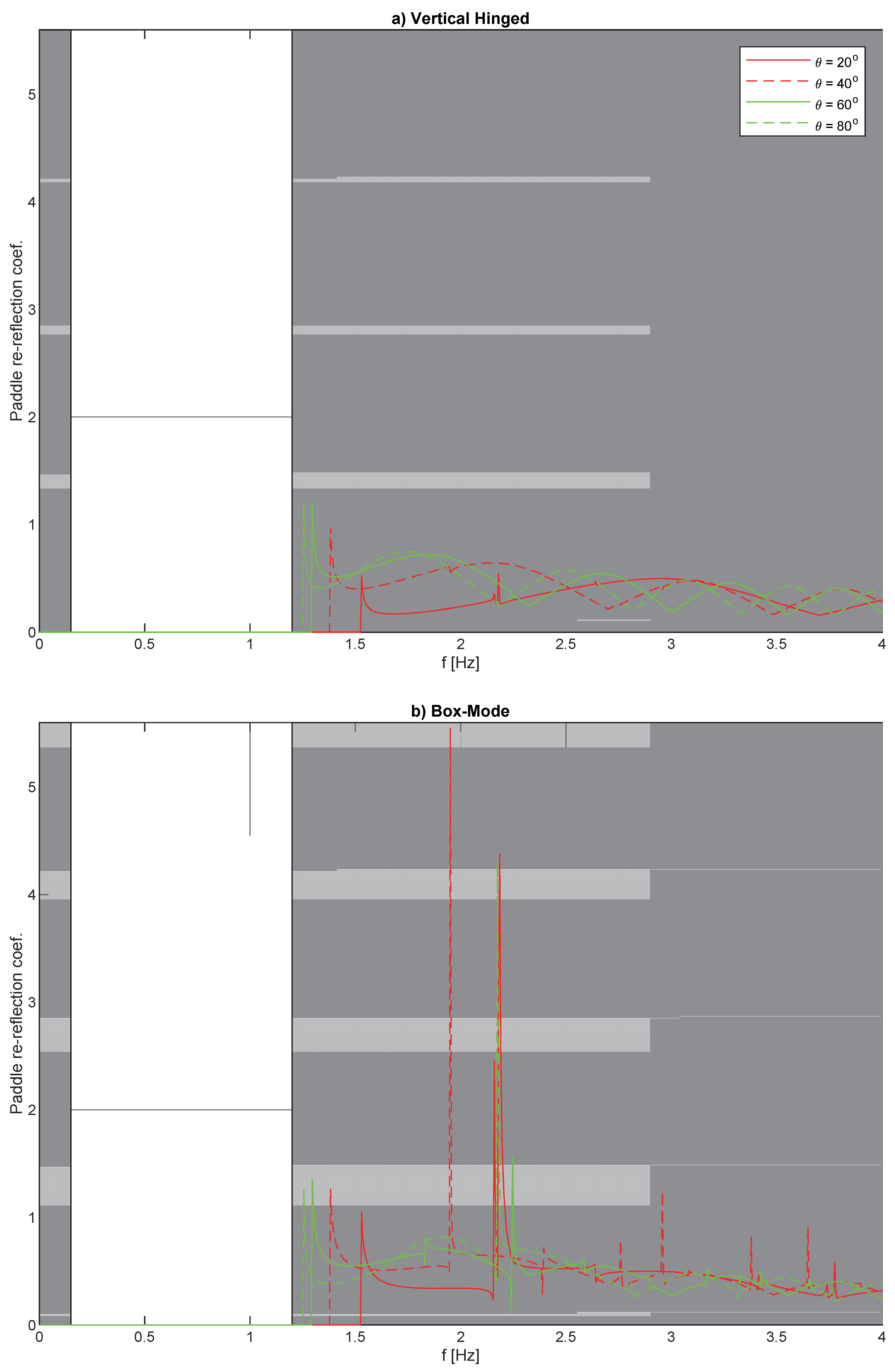
6.2. Re-Reflection Coefficient in Other Directions (p ≠ 0)
Using Equation (46), the theoretical performance curves for the re-reflection in other directions than the re-reflected wave are calculated for the case with
dwg = 0. Performance curves are given in
Figure 5 for vertical hinged and box-mode segmented wavemakers (Equations (44), (46), and (47)). Only the
p value with the highest re-reflection coefficient is presented in
Figure 5.
The figure shows that for vertical hinged paddles, the re-reflection coefficient in other directions than the re-reflected wave (p ≠ 0) only slightly exceeds unity and only in a very narrow frequency band around the singularity for p = 1, and only for high obliquity of the incoming wave to be absorbed.
For box-mode systems, very high re-reflection coefficients are found for many p-values (p ≠ 0) around the singularities. However, as the very high re-reflection coefficient occurs in a narrow frequency band, it might not cause major stability issues, as amplitude dispersion is expected to set an upper limit to the growth of the energy at these singularities. The main stability issues are expected to be those caused in the direction of the re-reflected wave, as discussed in the previous section, where the re-reflection coefficient exceeded unity in a wider frequency band. However, it cannot be ruled out that for box-mode systems, re-reflections in other directions might also lead to stability issues.
7. Discussion
Short-crested waves in laboratories are generated by summing a number of components with various directions. A segmented wavemaker may be used to generate and absorb waves from many directions simultaneously. Generating a single oblique wave component in the laboratory means that the wavemaker front should form a sinusoid. Segmented wavemakers are most typically discretized with stepwise constant approximation (box-mode paddles) or stepwise linear approximation (vertical hinged paddles). When generating oblique waves with a segmented wavemaker using the aforementioned approximations, spurious waves cannot be avoided. This is because the wavemaker is unable to form the theoretical sinusoid. For identical segment widths, spurious waves are much higher with box-mode paddles than with vertically hinged paddles.
Active wave absorption at the wavemaker is used to absorb reflections from models or boundaries in the wave basin. When designing nearfield active absorption systems, the absorption performance is maximized in a defined frequency and direction range, but also taking into account that the system at every frequency should be stable. Previous studies ignored spurious waves when they derived the theoretical performance and stability of active absorption systems. The influence of this choice is studied in the present paper.
By utilizing the existing methodology to calculate nearfield surface elevation including spurious waves, the methodology to calculate the theoretical performance of active absorption systems for segmented wavemakers including spurious waves is given. The obtained results demonstrate that ignoring spurious waves in stability estimations of active absorption systems with box-mode paddles is very unsafe for oblique waves. In fact, unstable systems might easily be designed.
The theoretical derivations made herein were based on monochromatic linear waves generated by an infinitely long segmented wavemaker. Short-crested waves are multichromatic, and thus, each component in the sea states will behave as predicted in the present paper; thus, stability issues are exactly the same in that case. Wavemakers in wave basins are not infinitely long, but are truncated; thus, the above findings will depend on the wavemaker length and the reflectiveness of the basin boundaries and models. Stability issues are important, even though they occur outside the frequency band where the main energy exists. This is because even though no first order energy is generated by the wavemaker at such high frequencies, they will occur regardless, due to superharmonic interactions or interactions with structures. Remember also that active absorption filters are designed with an attenuation at higher frequencies. The attenuation can, however, not be too steep, as that would cause significant phase disturbances. Thus, depending on the basin configuration, even a small amount of unwanted energy might build up over time and lead to an unstable system. Energy might also be introduced at the problematic frequencies due to electrical noise in the wave gauge signals.
If energy builds up at certain frequencies, the waves become nonlinear, which might set an upper limit on the built-up energy. Thus, future work is needed to study the phenomena presented in a nonlinear numerical model or in a physical model with a truncated wavemaker.


