Review

Best Practices for Shale Core Handling: Transportation, Sampling and Storage for Conduction of Analyses

1
Department of Earth Sciences, University College London, London WC1E 6BS, UK
2
Department of Chemical Engineering, University College London, London WC1E 7JE, UK
*
Author to whom correspondence should be addressed.
J. Mar. Sci. Eng. 2020, 8(2), 136; https://doi.org/10.3390/jmse8020136
Submission received: 9 January 2020 / Revised: 10 February 2020 / Accepted: 12 February 2020 / Published: 20 February 2020
(This article belongs to the Section Geological Oceanography)

Abstract

:
Drill core shale samples are critical for palaeoenvironmental studies and potential hydrocarbon reservoirs. They need to be preserved carefully to maximise their retention of reservoir condition properties. However, they are susceptible to alteration due to cooling and depressurisation during retrieval to the surface, resulting in volume expansion and formation of desiccation and micro fractures. This leads to inconsistent measurements of different critical attributes, such as porosity and permeability. Best practices for core handling start during retrieval while extracting from the barrel, followed by correct procedures for transportation and storage. Appropriate preservation measures should be adopted depending on the objectives of the scientific investigation and core coherency, with respect to consolidation and weathering. It is particularly desirable to maintain a constant temperature of 1 to 4 °C and a consistent relative humidity of >75% to minimise any micro fracturing and internal moisture movement in the core. While core re-sampling, it should be ensured that there is no further core compaction, especially while using a hand corer.

1. Introduction

Drill cores are important to develop geological models and plan exploration programs, providing data for a formation at in-situ conditions. Core data is integrated with field studies and log measurements to gain a complete and detailed understanding of a formation [1,2,3]. Shale cores undergo alteration as they are brought to the surface due to changes in pressure, temperature, and oxidation state from subsurface conditions. The shale reservoir can lose a significant quantity of accumulated gas and oil, both free and adsorbed, during the lifting process, which can impact economic analyses of the gas and oil in place. In a conventional hydrocarbon system, Total Organic Carbon (TOC) is a critical parameter to assess the quality of the shale source rock. A drop in pressure during core retrieval can lead to vapourisation or expulsion of the generated volatile hydrocarbon components present, resulting in decreased measured TOC values [4]. It is important to adopt appropriate core handling procedures during transportation, sampling, and storage to eliminate or limit any alteration, physical or chemical, so that the fluid properties are preserved. With appropriate handling procedures and preservation methods, any physical alteration of the rock material can be minimised so that it is as near a representative of the formation as possible. This is particularly important in the current scenario, where, with the possibility of shale gas exploration [5], it will be important to preserve the retrieved cores in the best possible condition for scientific investigation and future referral. This should ensure minimum deterioration for maximum scientific value in terms of obtaining reliable information from their analyses. In turn, this will be fundamental to guide decisions on shale gas exploitation, both from economic and environmental perspectives. Shale cores, in combination with outcrop samples, are also widely used for palaeoenvironmental research by studying their depositional conditions using geochemical and palaeontological tools [6]. In a previous study, the importance of adopting adequate storage environments and successful conservation treatments for geological samples, in line with other museum collections, has been noted [7]. However, so far, to the best of our knowledge, no study has focused on preservation methods pertaining specifically to shale drill cores.
A shale is, by definition, a sedimentary rock composed of silt or clay-sized particles or mud with the size of the constituent particles between 0.002 to 0.06 mm (less than 1/256 mm in diameter). Compositionally, the primary inorganic components are clay minerals, quartz, feldspar, calcite, and heavy minerals like apatite and pyrite. Of these, the pelitic sediments are dominated by fine grained clays (kaolinite, illite, montmorillonite/smectite), white micas (muscovite, phengite, paragonite), and chlorite. The organic and biogenic components include algal remains, spores, plant remains and biogenic quartz from the shells of organisms, thin walled gastropods, brachiopods, and faecal pellets. Shales are fissile, implying they can easily split along their bedding planes that separate each of the layers or strata in the rock.
Some related attributes and terminologies associated with a hydrocarbon system are listed in Table 1. The essential elements of any conventional hydrocarbon system include a hydrocarbon source rock, reservoir rock, and cap rock. Organic rich shales serve as source rock for hydrocarbon generation, and can be an important element of the conventional hydrocarbon system along with reservoir and seal (Figure S1). A potential source rock is routinely analysed for organic matter (OM) richness (TOC) and its thermal maturity and type, to identify possible hydrocarbon generation. As they are fine grained and clay-rich, when subjected to heat and pressure during deposition, they are extremely compacted with very low permeability and effective porosity. Consequently, they have the potential to become tight cap rocks for hydrocarbon trapping. Shales also make good reservoirs, acting as natural barriers to the migration of oil and gas as generated hydrocarbons remain trapped, accumulating in the free or adsorbed forms. So, it is no surprise that gas shale can be considered as unconventional reservoirs where regionally extensive to form continuous hydrocarbon accumulations (Figure S1). The term ‘gas shale’ is often used very loosely and does not always specifically take into account the lithology of the reservoir. Instead, it encompasses the lithological variations in shale units, thereby including not only shales hosting natural gas, but also mudstones (non-fissile shales), siltstones, fine grained sandstones, or even interlaminated sandstone–siltstone–shale rocks [8]. Based on their composition, gas shales are often described as ductile or brittle, commonly calculated as brittleness index (BI) [9,10]. While ductile shales are organic and clay mineral rich, brittle shales are enriched in silica (biogenic and/or detrital quartz), and/or carbonate (calcite/dolomite) minerals [9].
B I = Q u a r t z + D o l o m i t e + C a l c i t e Q u a r t z + D o l o m i t e + C a l c i t e + C l a y s + O M
In order to evaluate the source rock potential of a shale, it is conventional to assess its depositional environment and burial depth along with its fractures and pore spaces, besides the thermal maturity and TOC content [6,15]. Study of shale from different cores, occurring as layers with different distribution of minerals and formation of bedding fractures, can help in understanding the basin evolution with respect to sea level changes, climate and/or regional thermal uplift, and subsidence [16,17]. Unlike outcrop samples, the shale core is less prone to loss of TOC or any major and trace elements, as well as volatiles including trace gases [18,19]. It is challenging to get representative, intact samples from heterogeneous banded fissile shales, especially to look into elemental and isotopic composition of trace gases to evaluate the hydrocarbon potential of their reservoirs. In hand specimen of shales, apart from the presence of laminae, although they may appear to be homogenous without any observable grain size variability or textural attributes, they can be highly heterogeneous on the scale of a thin section.
After the retrieval of any shale core, it is important to ensure that structural integrity is maintained, and unwanted drying, evaporation, and oxidation is avoided. There are many methods available for preservation, but the choice of procedures and method adopted is largely dependent on the mineralogy and alteration state, and the target of the research and/or analyses. Preservation and cleaning techniques can be adopted so as not to disturb the chemical characteristics of the rock and avoid potential contamination via contribution and exchange of trace gases with external sources, e.g., paints, coats, solvent, purged gases, etc.
The presence of organic matter in shales provides soft inclusions for local redistribution of stresses. The contacts between the organic and inorganic matter are weak and prone to tensile and shear failure. Fractures in shales range from hairline to significantly wide and can get fully mineralized. These mineralized veins are generally pervasive with sub-vertical to sub-horizontal orientations. The complex fabric results in heterogeneous distribution of properties with their preferential orientations leading to anisotropy of the different material properties that subsequently affect their strength and porosity of the rock. As a result of the complex rock fabric of shale and their weak organic/inorganic contacts, they are prone to micro fracturing during coring and core retrieval. The porosity in shales manifests in different ways, such as intragranular pores, dissolution pores due to mineral alteration, interstitial pores between clay packages and micro fractures, and fissures in micas [20]. The presence of pores eventually dictates their stability and failure limit.

2. Durability of a Shale Core

The durability of a rock is its capacity to retain its original size, strength, and appearance over a long period, related to their mineral composition and texture, also affected by the climate and other local conditions. Shales are prone to weathering, leading to decay and loss of strength. Generally, a consolidated (well-cemented and hardened) core is more durable (Figure 1A,B), while an unconsolidated (compacted sediments lacking coherence with minor cement to harden) core, and that which is fractured, need more care (Figure 2). Also, an unweathered core is more durable than a weathered one. An unweathered sample can be distinguished from a weathered one based on lack of discolouration with unchanged surface characteristics and preservation of original texture. The grain boundaries remain intact and the fractures are essentially closed and cemented. If any secondary infilling of fracture is present, it would be considerably thin with respect to the total fracture thickness. In contrast, a highly weathered sample is considerably discoloured with thick infilling of fractures. The surface can be friable and pitted and the grain boundaries can be separated as a consequence of selective alteration and dissolution of less resistant minerals. The friable particles and the loosely bounded grains are prone to crumbling and affect robust sampling for analyses.
Deterioration of a shale can be identified on the basis of any observed discolouration and open fractures, with discolouration extending outwards from the fracture planes. Alteration of surface characteristics with lack of preservation of original texture and grain boundaries are also clear indicators of a deteriorated specimen. However, even for a well-preserved core, the timing of the analysis for shale core can be important and may affect the accuracy of any estimation of its reservoir hydrocarbon potential. A variety of techniques have been developed to analyse the shale cores for estimation of hydrocarbon in place, such as canister desorption tests and pressurised sidewall cores [21,22,23], the techniques either preventing or accounting for the loss of any desorbed gas component over time. However, using preserved waxed cores for gas estimation may be subject to erroneous estimates [24]. The essential background information on shale core that should be made available prior to any standard laboratory analyses, such as determination of TOC, vitrinite reflectance, or thermal alteration index for a source rock, or porosity, permeability, and hydrocarbon measurements for a shale reservoir, are listed in Table 2.

3. Alteration in Shale Core during Retrieval

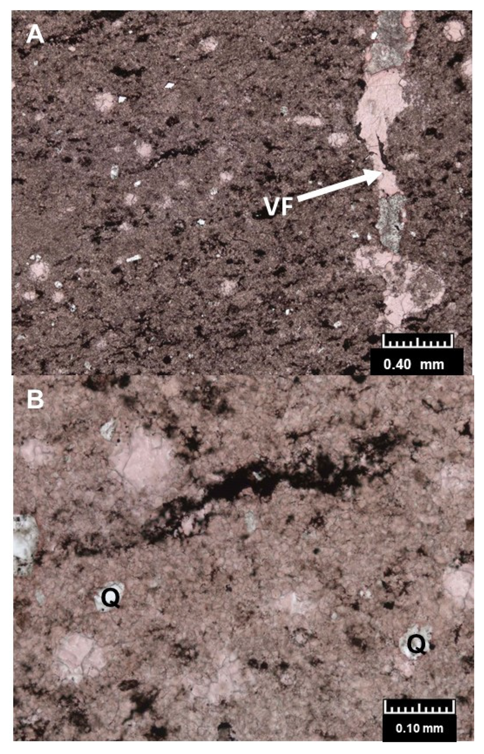
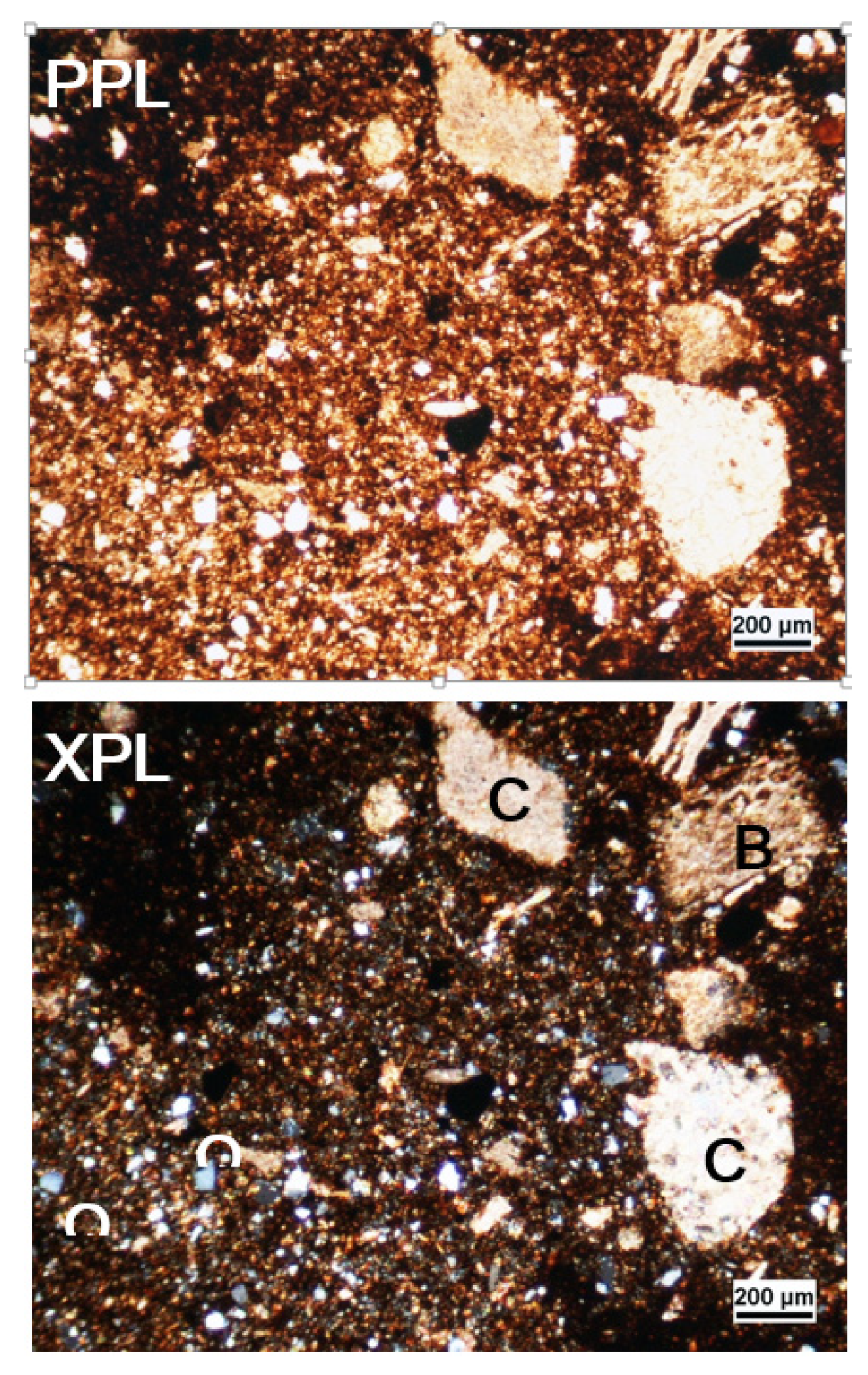
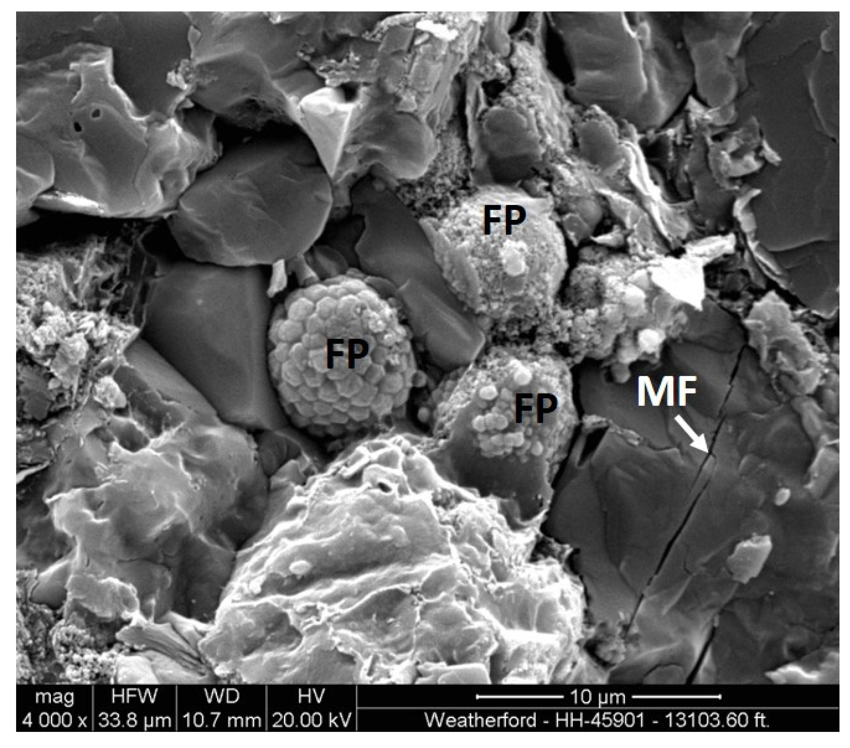
3.1. Micro fracturing due to Stress Relief/Water Intrusion

The formation of micro fractures in a shale core (Figure 3) is very common and fundamentally related to its heterogeneous microstructure pertaining to grain boundaries, pores, cracks, bedding planes, and minerals [25]. During coring and core retrieval, stress unloading and core relaxation can induce a large number of partings, resulting in the formation of micro fractures [24]. Also, as the core is extracted from in-situ conditions, the core expands gradually due to de-compaction or stress relief and other effects over time such as slow gas evolution, leading to inelastic deformation and volumetric expansion sometimes in excess of 6 to 8% [26,27]. This results in an increase of porosity and significant increase in permeability leading to inconsistent results in their measurements. Consequently, wellsite and preserved waxed core analyses are required to be factored in, or be corrected for possible stress relief-induced rock and micro-fracture alterations.
The micro fractures formed can be a pathway for water intrusion, the effect of which has been observed under high power, scanning electron microscope with a resolution ratio, and magnification of up to 3 nm and 200,000, respectively [28]. As the micro fractures progressively propagate, bifurcate, and connect with each other, they develop into macro fractures. If the macro fractures coalesce along bedding planes, there can be rock failures in blocks. Ideally, if an expanded core is re-compacted in the laboratory, the majority of the micro fractures and fractures should be resealed and should not re-open during further unloading owing to friction or permanent deformation [29,30,31]. However, due to the inherent anisotropy of shale owing to oriented clay minerals, they tend to have higher deformation in a direction perpendicular to the bedding rather than parallel to it, subjecting the micro fractures to shear displacement. Consequently, they might be more difficult to close by reloading [24]. Alternatively, for reliable assessment, the rock can be crushed to mm sized fragments and then sieved to a size that is generally a good representative of the overall matrix structure, thereby eliminating the coring induced micro fractures [32,33]. However, crushing may eliminate micro Darcy (and higher) permeability, especially in texturally complex, siltier, or sandier unconventional reservoirs [24]. Also, care must be taken for shale where organic matter and clay content exceeds 43% as, due to their matrix-supported fabric, they are likely to have lower elastic modulus, higher compressibility, and a greater stress sensitivity coefficient [27]. This renders them prone to plastic shear and contraction and alteration of their pore structure [34]. Also, shales show anisotropic directional permeability that can be attributed to their laminations [35]. The core can be subjected to repeated hydrostatic loading and unloading cycles in the laboratory, a procedure known as seasoning. This diminishes any evolution of the shale within a number of cycles, after which measurements become reproducible and reliable [29,36]. However, it is still possible that the seasoning has resulted in closure of the stress-relief micro fractures and compaction of the softer components, such as the clay minerals and the organic matter, without the rock reverting back to its in-situ conditions [26].

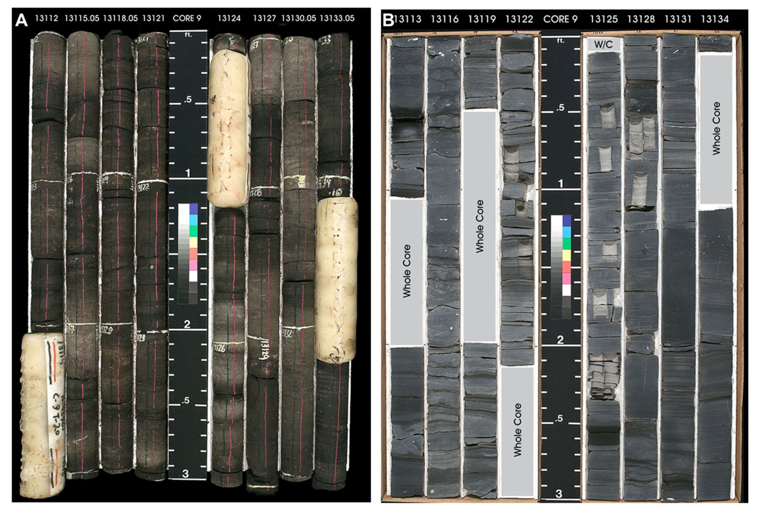
3.2. Dessication of Cores due to Water Loss

On exposure to air, the water content of shale can be altered significantly, resulting in the development of shrinkage or dessication cracks that can compromise with any further testing. Change in water content is a function of the relative humidity to which the shale is exposed [37,38,39]. The value of the relative humidity which results in zero change in the water content is referred to as the shale’s native activity. In order to maintain the water content very close to the shale’s native state, the relative humidity value of the exposed air has to be controlled which, for a water saturated shale, is greater than 75% and often more than 90% [40].

3.3. Clay Minerals and Shale Instability

Clay minerals, particularly smectite in shale, can be related to volume expansion following osmotic swelling of interlamellar spaces [41]. This is unlikely to occur at depth under high temperature and pressure, as charged sites within and on the clay mineral would not be accessible to exchangeable cations for any compacted, impermeable shale. However, closer to the surface, access to charged sites may be facilitated by development of micro fractures and increasing permeability. Shale stability is also affected during drilling due to water infiltration from the drilling mud. This can be restricted by addition of nanoparticles, such as TiO2, to the water-based drilling mud in appropriate concentration [42].

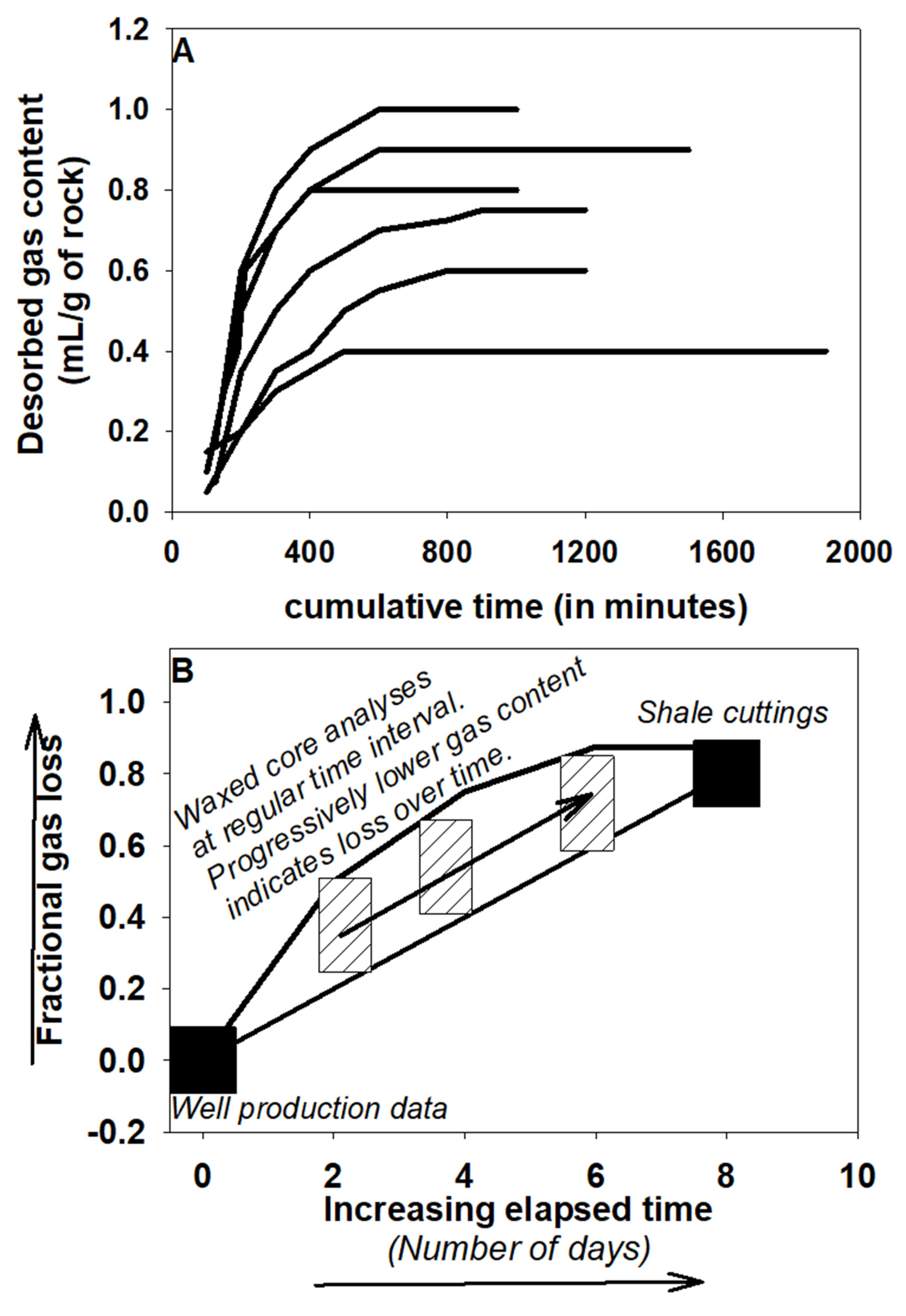
3.4. Fluid Expulsion and Losses

Proper evaluation of initial fluid saturations is essential for reserve estimation, evaluated using log techniques, and, more accurately, by direct measurements of fluid saturation from in-situ core samples [43]. However, obtaining the initial fluid saturation that exists in the porous media of a core is not straight forward as it can be affected by flushing by the coring fluid, as well as degassing and fluid losses [43,44]. Fluids in shales are contained in the pore system as a free phase, or as a soluble phase dissolved in liquid phases. When the core is retrieved to the surface, the pressurised fluids expand and are pushed from the pore space of the core, also displacing the mobile hydrocarbon and/or water from the pore system. The gas evolution and thermal contraction associated with the cooling of the core material from reservoir temperature result in the shrinkage of the in-situ fluids. To an extent, this can be addressed by pressure coring, maintaining the ambient pressure in the samples until further procedure (e.g., cryogenic freezing of contained fluids). Since the water content of the cores may be immobile, and in various forms, the pressurised sidewall core may not lead to accurate estimation of Swi (initial water saturation).
Water saturation can be determined based on laboratory measurements on crushed samples (Dean–Stark distillation method) but it fails to distinguish between the free and capillary-bound/interlayer water components [45]. Alternatively, the total porosity, in conjunction with the velocity of waves in shale reservoirs, can be used to estimate the water saturation [46]. However, methods based on resistivity and porosity are not always feasible in shale reservoirs rich in organic or conductive minerals [47,48]. Besides, drying and crushed core analyses, routinely used for quick measurements of total porosity during shale core analyses, based on grain density and bulk density (Gas Research Institute or GRI method) is associated with significant uncertainties related to the crushing process and the relative humidity of the measurement environment [49]. More effectively, integration of in-situ saturation techniques such as CT scanning can be used to distinguish between the different water components. Sponge coring to trap any expelled fluid for analysis in an absorbent sponge material surrounding the core, followed by extraction of all reservoir fluids from both the core and the sponge, can also be an alternative solution [50].

4. Best Practices of Core Handling

Some of the changes in shale cores as they are retrieved are unpreventable and irreversible, while others can be reversed, and the original state of the core can be restored. Still, others do not interfere with core measurements when appropriate analytical procedures are employed. Some general practices for core handling in terms of removal from barrel, storage, and preservation have been discussed previously [50,51,52].

4.1. Removal from Barrel

Cores should be removed from the barrel as soon as possible to minimize drilling fluid imbibition into the porous shale. The latter can lead to changes in fluid saturations, geochemical and gas solution equilibrium, clay swellings and mobilization of interstitial clays and fine-grained minerals, leading to the degradation of mechanical properties. The swelling is pronounced for certain clay minerals like smectite and vermiculite, related to an increase in layer spacing when water enters the interlayer, one layer of water molecules at a time, if there is any increase in relative humidity [53].
The core should be removed, preferably in a horizontal position with minimum mechanical impact during extraction. It can be slid out by slightly elevating the top end of the barrel. Failing this, a rod can be used to push the core out of the barrel, or the barrel can be gently tapped to initiate movement of the core.
It is important to maintain the orientation and the sequence of the core at all times using appropriate markings with well-labelled core depths. This can be done on the rig floor itself where the core can be laid out and boxed, or placed in marked trays (Figure 4A). Any excess drilling fluid on the surface can be wiped out using a clean drilling fluid saturated cloth and wrung out as often as needed. However, there should be no prolonged contact with any paper or other material with fine capillaries that can trigger fluid losses.

4.2. Storage and Preservation of Core

For the short term, it is convenient to store a core as-is by sealing the ends of a disposable inner barrel or liner using tight-fitting plastic or rubber end caps. For longer periods, suitable plastic, aluminium, or fibreglass tubes, also capped and sealed, can be used. Metal and corrugated plastic trays are commonly used to place the tubes. In all cases, the core holder should have a good size match with the core. A poorly consolidated core should be slabbed before storage. Its length should not exceed 9 m to protect the lower section from damage and compaction from the overlying weight. Samples can be slabbed at regular intervals perpendicular to the core axis (Figure 4B). Generally, cores are cut into slabs in 1/3 and 2/3 ratios. Core plugs are also convenient to store, where they are extracted from the whole core or slabs at fixed distances with a definite orientation e.g., parallel to bedding [55], or perpendicular with respect to oriented mineral grains or bedding planes [56]. Once the core is slabbed or sectioned, Styrofoam inserts should be used to minimise any further movement. If Styrofoam inserts are not available, bubble wrap might also suffice.
Sometimes, it may be necessary to preserve the core using special methods. For example, if it has abundant pyrite and carbonate minerals (Figure 3), oxidation of pyrite and the resultant sulphuric acid driven dissolution of carbonate can occur in a significant scale within a short time period, as observed from the study of pyrite-bearing shales and calcareous sandstone in the landslide prone eroding mountains of Taiwan [57]. Immediate preservation of the core will be necessary, which will also prevent it from any further mechanical destabilisation. Additionally, it will offer protection from exposure to extreme temperature and direct sunlight, rain, or strong winds.
Different preservation methods were used depending on the type of core sample (consolidated/unconsolidated) and the purpose of study. Some common preservation techniques are discussed below:
Wrapping with a masking or fibreglass packaging tape: The tape is wrapped tightly around core segments perpendicular to the fissility planes for mechanical stabilization and reducing the rate of evaporation. Heat shrinkable plastics can also be used as a wrapping, although it is not an absolute oxygen or water vapour barrier. Care should be taken so that there is no entrapped air between the core and the wrapping. Core lamination using heat sealable plastic laminates: It acts as impermeable barrier to water vapour and protects the core from chemical alteration and degradation by fluids. However, the process involves exposing the core to temperature of 350 to 450 °C that can be detrimental for volatile analyses and can lead to the loss of (OH) water from the lattice structure of the clay minerals. Shrink wrapping using a suitable barrier film: This is a cost-effective and fast method of core preservation that can be done either manually or automatically [58]. The wrapping material is composed of molecules that stretch as a part of the manufacturing process but shrink around the core during wrapping when subjected to heat. As the heat is just applied for a few seconds, it only affects the shrink film. The method has been used for preserving core in the Gulf Coast Repository and is especially recommended for weakly bound core with high moisture content [58]. The right selection of the barrier film, which is generally multi-layered with suitable water vapour and oxygen transmission rates, is very important. Vacuum packaging/sealing core: This involves the removal of air from the core container, offering protection from dust and moisture and against dehydration. Compressed packaging can also help to stabilize fragmented cores. The technique has been applied successfully in some IODP (Integrated Ocean Drilling Programme) core repository, although the long-term effects on physical and geochemical properties, when stored below atmospheric pressure, are still uncertain [58]. Dipping in wax seal (Figure 4A): The standard procedure involves wrapping the sample with plastic film and aluminium foil before dip coating it in wax multiple times [59]. Care should be taken as prolonged exposure exceeding five minutes has shown to result in fluid losses and a reaction with the wrapping. The type of wax can be critical so that it does not degrade and lead to fluid losses from the sample. It is important to maintain a homogeneous wax composition and consistent temperature during the procedure. However, the plastic and wax are permeable and do not serve as barriers to oxygen or water vapour and the reliability of this preservation techniques for cores to be analysed for trace gases is debatable [59]. A combination of wax-wrapped sample analyses over time, along with cuttings and extrapolating measurements to initial in-situ reservoir conditions, can provide an insight (Figure 5). This may be a potential method of gas measurement in shales under reservoir conditions. In order to protect the core from the heat of the wax, a thermal barrier can be used. Immersion in liquid within an anaerobic jar: The sample core/plug can be immersed in a liquid such as simulated formation brine contained in a deaerated jar, which can be subsequently pressurised. The method is not suitable if the core is to be assessed for fluids, as exposure to the immersion liquid results in imbibition of that fluid and alteration of saturations [50]. However, the technique has been successfully applied to shale core preserved for hydraulic fracturing tests [60]. Core samples for analyses were extracted by well-boring at the centre of bubble-wrapped cores after unwrapping, and then placed in mineral oil to avoid contact with water and air. The samples were then analysed following caps and casing cementing.

4.3. Transportation

Some best practices for core transportation have been discussed in previous studies [50,59] that can be also applicable for shale cores with suitable modifications. For short distances, the core/sections can be transferred using labelled wooden boxes, properly cushioned with wood lids secured using screws. For long distance transport, the core should be secured in a transport container like an insulated box or a refrigerated unit. The temperature should be monitored and maintained at a constant 4 °C, as shales are highly sensitive to temperature changes and prone to oxidation, particularly the ones with organic content of >20%. While chilling can prevent fluid evaporation, it is important to ensure that freezing of shales does not occur as it can lead to massive microfissuring and internal moisture movement. Freezing also tends to change the volume of the core, depending on water content. Freeze–thaw leads to the redistribution of fluids within the fine-grained shale groundmass forming the sediment matrix, as a consequence of changes in constituent grain dimensions and their interstitial space network. The use of unprotected glass jars, deformable plastics, paper cartons, and non-rigid containers are not recommended for core transportation. Some degree of mechanical stabilization to the core can be provided by chilling but, additionally, consolidated core can be wrapped in bubble wrap or other suitable cushioning material. For any unconsolidated or fractured core, mechanical stabilization can be achieved by epoxy, wax, resin, or foam injection, with the casting material completely conforming to and encasing the core surface. Of these, resin has low viscosity and can fill in the fine fractures and sometimes may impregnate the core and displace pore fluids. Although casting will preserve sediment structure and texture to an extent, it is not recommended for chemical analyses and isotopic studies due to potential contamination. Transportation can be by air or ship but, in the case of air transport, the storage cabin may not be pressurised which may affect the preservation of the core. For shipment, it would be best to cut the core into 0.9 m lengths, each labelled to represent its position in the sequence of cut lengths, along with corresponding depths and orientation lines. If the entire core is to be shipped as a single piece, a splint should be used (to prevent it from flexing) and the ends should be capped. It is always best to maintain the core in an upright position during transportation without any stacking.

5. Sampling

It is important to ensure before sampling, that the core is warmed to the ambient temperature if it has been stored under refrigerated conditions. Samples should be selected so that they are representative, which is particularly challenging for shale core with varying lithology and heterogeneous porosity types. For fluid saturation assessment, as well as volatile studies, it is best to sample right after the retrieval of the core from the barrel to prevent evaporative losses of fluid and adsorption of contaminants that can lead to an alteration of sorption characteristics and surface properties. For trace gas studies, it is best to sample from the desired depths of sediment core using copper tubes, connected to the core via fittings that can be sealed at both ends using standard clamps [61]. Prior to sampling and laboratory measurements, it is generally customary to clean the core through flushing, flowing, or using various solvents. However, if the study focuses on the original fluids and other volatile elements, these standard cleaning procedures are best avoided. In the same context, washing with any water or oil is not advised as it can lead to contamination for isotopic analyses. For future references, if any intact measureable length of the core has to be removed, a note or block has to be left in its place stating details of length, lithology, and reason(s) for removal.
Samples can be obtained using a hand corer, but care should be taken that they do not tend to further compact the sediments. For shales, chip samples or slices can be taken at naturally occurring breaks in the core using a precision trim saw/stainless steel or Teflon cutter. The final cut can be made using a sharp knife, or a Teflon or nylon string can be used for slicing the core. Because of their fissile nature they can be cut as disks using a precision hammer saw and/or Teflon strings along the fissility planes or other planes of weaknesses. Sediments in contact with the saw blade/knife should be used with caution for elemental and isotopic analyses due to potential contamination. It is advisable to discard the outer 1–2 mm layer of sediment that has been in contact with the plastic or metal liner for potential contamination, especially for isotopic and elemental analyses. Extracting samples from the central portion of any drill core for geochemical analyses can minimise the superficial effects of core retrieval and contamination from handling e.g., [15,60,62,63,64]. Hammering should be avoided as it can damage the core. Following such standard core sampling procedures as these recommended practices will ensure that the results from the studies are independent of human bias.
Each sample (and/or subsample) should be kept in a labelled, clean, and chemically inert container in darkness and refrigerated to a temperature of 1 to 4 °C. Humidity control is another important aspect for shales since they have moisture-sensitive clay minerals. This can be achieved with specially designed ovens. Polyethylene plastic or Teflon containers are most suitable as they are less likely to add chemical artefacts or interferences and are not as fragile as glasses [59]. The size of the container should be as close to the volume of the sample as possible to minimize the head space in the container. Plastic bags can be a convenient and cheap means of sample storage but are only recommended for short periods. To minimize air space, any excess bag can be folded against the sample and taped to assure a tight fit.

6. Conclusions

Drill core shale samples need to be handled and stored with care to maximize their utilisation for scientific studies. Shales are susceptible to micro fracturing and volume expansion due to cooling and depressurisation during retrieval to the surface. This affects their porosity and permeability measurements, as well as giving rise to erroneous initial fluid saturation estimates. To an extent, fluid losses and expulsion can be prevented by pressure coring, where the samples are maintained under ambient pressure conditions until further procedures. Alternatively, sponge coring to trap any expelled fluid in a surrounding sponge material can be a solution.
Best practices for core handling start right from its retrieval while extracting from the barrel. The recommended practice would be to remove the core in a horizontal position with minimum mechanical impact, by sliding it out by slightly elevating the top end of the barrel. Cores are best preserved as slabs and core plugs in fixed ratios and orientation. For further protection, they can be wrapped using fibreglass packaging tape or sealed with wax, although the reliability of the latter for trace gas analyses needs caution due to contamination issues. A combination of wax-wrapped sample analyses over time along with cuttings, and extrapolating measurements to initial in-situ, a reservoir condition can be a reliable method of gas measurement in shales. Shale cores should be transported and stored appropriately at a constant temperature of ~4 °C to prevent any microfissuring and internal moisture movement. It is important to ensure that they are mechanically stabilised using suitable inserts or by casting with epoxy, wax, or resin. Shale core can be stored in aluminium or fibreglass tubes, capped and sealed, or placed in metal and corrugated plastic trays that have a good size match with the core. For sampling, a hand corer can be used, and the central portion of an intact core would be the best target. Samples can be stored in Polyethylene plastic, Teflon, or closed or airtight containers.
Inappropriate storage before analysis can result in up to a 38% decline in gaseous and light hydrocarbons (up to C10) over a period of less than a day, based on Rock–Eval analyses [64]. The loss is strongly governed by the TOC content of the shale, with high TOC (>11%) significantly limiting the loss over time. Based on our analyses of samples extracted from the central portions of three slabbed cores stored in a warehouse in North Wales, after storage of samples for over a year under refrigerated conditions in Teflon containers, their isotopic measurements (δ13Corganic ~ −27‰) demonstrate consistent results, in agreement with previous studies [62,65]. The porosity measurements show a depth trend with noble gas isotopic (40Ar/36Ar) and elemental (4He/40Ar) ratios, thereby ruling out any alteration and gas losses due to handling and storage post-retrieval of the cores [63]. The consistency of the noble gas results is significant as they were carried out in two batches with one year between the analyses. No trend in concentration with depth of the samples from the cores was observed, with data sets from both batches of analyses in reasonable agreement with each other. This clearly indicated that trace gases were preserved during storage of the samples with no losses related to inappropriate handling, although TOC content of the samples varying between 0.6–3.4 wt%, was not very high [54].

Supplementary Materials

The following are available online at https://www.mdpi.com/2077-1312/8/2/136/s1, Figure S1: Cartoon (not to scale) depicting hydrocarbon systems (conventional and unconventional).

Author Contributions

The original draft for the manuscript was prepared by S.B. followed by review and editing by A.J. and P.M. All authors have read and agreed to the published version of the manuscript.

Funding

Funding for this work was provided to SB by an industry consortium constituted by BG Group (now Shell), who also provided the cores referred to in this article, under award 159877. The storage of the cores are facilitated by CGG in Conwy, supported by funding to AJ from the European Union’s Horizon 2020 research and innovation programme under grant agreement No. 764810.

Conflicts of Interest

The authors declare no conflict of interest.

References

  1. Worthington, P.F. Effective integration of core and log data. Mar. Pet. Geol. 1994, 11, 457–466. [Google Scholar] [CrossRef]
  2. Al-Saddique, M.A.; Hamada, G.M.; Al-Awad, N.J. State of the Art: Review of Coring and Core Analysis Technology. J. King Saud Univ. Eng. Sci. 2000, 12, 117–138. [Google Scholar] [CrossRef]
  3. Yan, J. Reservoir parameters estimation from well log and core data: A case study from the North Sea Petroleum. Geoscience 2002, 8, 63–69. [Google Scholar] [CrossRef]
  4. Steiner, S.; Ahsan, S.A.; Raina, I.; Dasgupta, S.; Lis, G.P. Integrating Total Organic Carbon TOC in Source Rock Oil Plays. In Proceedings of the Abu Dhabi International Petroleum Exhibition & Conference, Abu Dhabi, United Arab Emirates, 7–10 November 2016. [Google Scholar] [CrossRef]
  5. Stephenson, M.H. Shale gas in North America and Europe. Energy Sci. Eng. 2016, 4, 4–13. [Google Scholar] [CrossRef] [Green Version]
  6. Wang, S.; Dong, D.; Wang, Y.; Li, X.; Huang, J.; Guan, Q. Sedimentary geochemical proxies for paleoenvironment interpretation of organic-rich shale: A case study of the Lower Silurian Longmaxi Formation, Southern Sichuan Basin, China. J. Nat. Gas Sci. Eng. 2016, 28, 691–699. [Google Scholar] [CrossRef]
  7. Baars, C.; Horak, J. Storage and conservation of geological collections—A research agenda. J. Inst. Conserv. 2018, 41, 154–168. [Google Scholar] [CrossRef] [Green Version]
  8. Rokosh, C.D.; Lyster, S.; Anderson, S.D.A.; Beaton, A.P.; Berhane, H.; Brazzoni, T.; Chen, D.; Cheng, Y.; Mack, T.; Pana, C.; et al. Summary of Alberta’s Shale- and Siltstone-Hosted Hydrocarbon Resource Potential; ERCB/AGS Open File Report 2012-06; Energy Resources Conservation Board: Edmonton, AB, Canada, 2012; p. 327. [Google Scholar]
  9. Mathia, E.; Ratcliffe, K. Brittleness Index—A Parameter to Embrace or Avoid? In Proceedings of the Unconventional Resources Technology Conference (URTeC), San Antonio, TX, USA, 1–3 August 2016. [Google Scholar]
  10. Slatt, R.; Abousleiman, Y. Merging sequence stratigraphy and geomechanics for unconventional gas shales. Lead. Edge 2011, 30, 274–282. [Google Scholar] [CrossRef]
  11. Zhao, J.Z.; Cao, Q.; Bai, Y.B.; Li, J.; Er, C.; Wu, W.T. Petroleum system: From conventional to unconventional. In Proceedings of the International Conference and Exhibition, Barcelona, Spain, 3–6 April 2016. [Google Scholar] [CrossRef]
  12. Schlumberger Oilfield Glossary. Available online: https://www.glossary.oilfield.slb.com (accessed on 19 June 2019).
  13. Mani, D.; Kalpana, M.S.; Patil, D.J.; Dayal, A.M. Organic Matter in Gas Shales: Origin, Evolution, and Characterization. In Shale Gas: Exploration and Environmental and Economic Impacts; Chapter 3; Dayal, A.M., Mani, D., Eds.; Elsevier: Amsterdam, The Netherlands, 2017; pp. 25–54. [Google Scholar] [CrossRef]
  14. U.S. Geological Survey. Available online: https://www.usgs.gov/faqs/what-hydraulic-fracturing?qt-news_science_products=0#qt-news_science_products (accessed on 19 June 2019).
  15. Basu, S.; Ahmed, J.; Jones, A.P.; Verchovsky, A.B. Characterisation of carbón components and their isotopic composition in gas shales. Energy Procedia 2018, 146, 47–52. [Google Scholar] [CrossRef]
  16. Wang, Y.; Li, Z.; Gong, J.; Zhu, J.; Hao, Y.; Hao, X.; Wang, Y. An evaluation workflow for shale oil and gas in the Jiyang Depression, Bohai Bay Basin, China: A case study from the Luojia area in the Zhanhua Sag. Pet. Res. 2016, 1, 70–80. [Google Scholar] [CrossRef]
  17. Kohl, D.; Slingerland, R.; Arthur, M.; Bracht, M.; Engleder, T. Sequence stratigraphy and depositional environments of the Shamokin (Union Springs) Member, Marcellus Formation, and associated strata in the middle Appalachian Basin. AAPG Bull. 2014, 98, 483–513. [Google Scholar] [CrossRef]
  18. Liu, Y.; Zhang, J.; Tang, X.; Yang, C.; Tang, S. Weathering characteristics of the Lower Paleozoic black shale in northwestern Guizhou Province, south China. J. Earth Syst. Sci. 2016, 125, 1061–1078. [Google Scholar] [CrossRef] [Green Version]
  19. Grovea, B.S.; Walshb, T.B.; Darrah, T.H. Using radiogenic noble gases to trace the conditions of crustal fluid migration. Procedia Earth Planet. Sci. 2017, 17, 818–821. [Google Scholar] [CrossRef]
  20. Ma, L.; Slater, T.; Dowey, P.J.; Yue, S.; Rutter, E.H.; Taylor, K.G.; Lee, P.D. Hierarchical integration of porosity in shales. Sci. Rep. 2018, 8, 11683. [Google Scholar] [CrossRef] [PubMed]
  21. Pinkett, J.; Westacott, D. Innovative Sidewall Pressure Coring Technology Improves Reservoir Insight in Multiple Applications. In Proceedings of the SPWLA 57th Annual Logging Symposium, Reykjavik, Iceland, 25–29 June 2016. [Google Scholar]
  22. Dang, W.; Zhang, J.C.; Tang, X.; Wei, X.L.; Li, Z.M.; Wang, C.H.; Chen, Q.; Liu, C. Investigation of gas content of organic-rich shale: A case study from Lower Permian shale in southern North China Basin, central China. Geosci. Front. 2018, 9, 559–575. [Google Scholar] [CrossRef]
  23. Wilson, K.; Padmakar, A.S.; Mondegarian, F. Simulation of core lifting process for lost gas calculation in shale reservoirs. In Proceedings of the International Symposium of the Society of Core Analysts, Napa Valley, CA, USA, 16–19 September 2013. [Google Scholar]
  24. Handwerger, D.A.; Suarez-Rivera, R.; Vaughn, K.I.; Keller, J.F. Methods Improve Shale Core Analysis. Am. Oil Gas Rep. 2012, 55, 80–89. [Google Scholar]
  25. Liu, S.; Wang, Z.; Zhang, L. Experimental study on the cracking process of layered shale using X-ray microCT. Energy Explor. Exploit. 2018, 36, 297–313. [Google Scholar] [CrossRef] [Green Version]
  26. Ma, X.; Zoback, M.D. Static and Dynamic Response of Bakken Cores to Cyclic Hydrostatic Loading. Rock Mech. Rock Eng. 2018, 51, 1943–1953. [Google Scholar] [CrossRef]
  27. Wu, Z.H.; Zuo, Y.J.; Wang, S.Y.; Sunwen, J.; Liu, L.L. Experimental Study on the Stress Sensitivity and Influence Factors of Shale under Varying Stress. Shock Vib. 2018, 2018, 3616942. [Google Scholar] [CrossRef]
  28. Liu, X.; Zeng, W.; Liang, L.; Xiong, J. Experimental study on hydration damage mechanism of shale from the Longmaxi Formation in southern Sichuan Basin, China. Petroleum 2016, 2, 54–60. [Google Scholar] [CrossRef] [Green Version]
  29. Scholz, C.H.; Kranz, R. Notes on dilatancy recovery. J. Geophys. Res. 1974, 79, 2132–2135. [Google Scholar] [CrossRef]
  30. Bernabé, Y. The effective pressure law for permeability in Chelmsford granite and Barre granite. Int. J. Rock Mech. Min. Sci. 1986, 23, 267–275. [Google Scholar] [CrossRef]
  31. Jæger, C.J.; Cook, N.G.W.; Zimmerman, R. Micromechanical Models. In Fundamentals of Rock Mechanics, 4th ed.; Chapter 10; Blackwell Publishing: Hoboken, NJ, USA, 2007; pp. 282–314. [Google Scholar]
  32. Handwerger, D.A.; Suarez-Rivera, R.; Vaughn, K.I.; Keller, J.F. Improved Petrophysical Core Measurements on Tight Shale Reservoirs Using Retort and Crushed Samples. In Proceedings of the SPE Annual Technical Conference and Exhibition, Denver, CO, USA, 30 October–2 November 2011. [Google Scholar]
  33. Tinni, A.; Fathi, E.; Agarwal, R.; Sondergeld, C.; Akkutlu, Y.; Rai, C. Shale Permeability Measurements on plugs and crushed samples. In Proceedings of the SPE Canadian Unconventional Resources Conference, Calgary, AB, Canada, 30 October–1 November 2012. [Google Scholar] [CrossRef]
  34. Wang, J.; Ge, H.; Wang, X.; Shen, Y.; Liu, T.; Zhang, Y.; Meng, F. Effect of Clay and Organic Matter Content on the Shear Slip Properties of Shale. J. Geophys. Res. Solid Earth 2019, 124, 9505–9525. [Google Scholar] [CrossRef]
  35. Backeberg, N.R.; Lacoviello, F.; Rittner, M.; Mitchell, T.M.; Jones, A.P.; Day, R.; Wheeler, J.; Shearing, P.R.; Vermeesch, P.; Striolo, A. Quantifying the anisotropy and tortuosity of permeable pathways in clay-rich mudstones using models based on X-ray tomography. Sci. Rep. 2017, 7, 14838. [Google Scholar] [CrossRef] [PubMed]
  36. Warpinski, N.R.; Teufel, L.W. Determination of the effective stress law for permeability and deformation in low-permeability rocks. SPE Form. Eval. 1992, 7, 123–131. [Google Scholar] [CrossRef]
  37. Gasc-Barbier, M.; Tessier, D. Structural modifications of a hard deep clayey rock due to hygro-mechanical solicitations. Int. J. Geomech. 2007, 7, 227–235. [Google Scholar] [CrossRef]
  38. Wan, M.; Delage, P.; Tang, A.M.; Talandier, J. The water retention properties of the Calovo-Oxfordian claystone. Int. J. Rock Mech. Min. Sci. 2013, 64, 96–104. [Google Scholar] [CrossRef]
  39. Ferrari, A.; Favero, V.; Marschall, P.; Laloui, L. Experimental analysis of the water retention behaviour of shales. Int. J. Rock Mech. Min. Sci. 2014, 72, 61–70. [Google Scholar] [CrossRef]
  40. Ewy, R.T. Shale/Claystone response to air and liquid exposure, and implications for handling, sampling and testing. Int. J. Rock Mech. Min. Sci. 2015, 80, 388–401. [Google Scholar] [CrossRef]
  41. Wilson, M.J.; Wilson, L. Clay mineralogy and shale instability: An alternative conceptual analysis. Clay Miner. 2014, 49, 127–145. [Google Scholar] [CrossRef] [Green Version]
  42. Mijić, P.; Gaurina-Međimurec, N.; Pašić, B.; Medved, I. The influence of TiO2 and SiO2 nanoparticles on filtration properties of drilling muds. Min. Geol. Pet. Eng. Bull. 2019, 34, 67–78. [Google Scholar] [CrossRef]
  43. Bennion, D.B.; Thomas, F.B.; Bietz, F.F. Determination of Initial Fluid Saturations—A Key Factor in By-Passed Pay Determination; Paper P0003–96; Hycal Energy Research Laboratories Ltd.: Calgary, AB, Canada, 1996. [Google Scholar]
  44. Bennion, D.B.; Thomas, F.B.; Ma, T. Determination of initial fluid saturations using traced drilling media. J. Can. Pet. Technol. 2001, 40. [Google Scholar] [CrossRef]
  45. Bratovich, M.W.; Walles, F.; Hughes, B. Formation Evaluation and Reservoir Characterisation of Source Rock Reservoirs. In Unconventional oil and Gas Resources Exploitation and Development; Chapter 8; Ahmed, U., Meehan, D.N., Holditch, S.A., Eds.; CRC Press: Boca Raton, FL, USA, 2016. [Google Scholar] [CrossRef]
  46. Liu, K.; Sun, J.; Zhang, H.; Liu, H.; Chen, X. A new method for calculation of water saturation in shale gas reservoirs using Vp-to-Vs ratio and porosity. J. Geophys. Eng. 2018, 15, 224–233. [Google Scholar] [CrossRef] [Green Version]
  47. Wu, P.; Aguilera, R. Investigation of gas shales at nanoscale using scan electron microscopy, transmission electron microscopy and atomic force microscopy. In Proceedings of the SPE Annual Technical Conference and Exhibition (Society of Petroleum Engineers), San Antonio, TX, USA, 8–10 October 2012. [Google Scholar] [CrossRef]
  48. Mashaba, V.; Altermann, W. Calculation of water saturation in low resistivity gas reservoirs and pay-zones of the Cretaceous Grudja Formation, onshore Mozambique. Mar. Pet. Geol. 2015, 67, 249–261. [Google Scholar] [CrossRef]
  49. Chen, F.; Lu, S.; Ding, X.; Zhao, H.; Ju, Y. Total Porosity Measured for Shale Gas Reservoir Samples: A Case from the Lower Silurian Longmaxi Formation in Southeast Chongqing, China. Minerals 2018, 9, 5. [Google Scholar] [CrossRef] [Green Version]
  50. Recommended Practices for Core Analysis. Available online: http://w3.energistics.org/RP40/rp40.pdf (accessed on 19 June 2019).
  51. U.S. EPA. Methods for Collection, Storage and Manipulation of Sediments for Chemical and Toxicological Analyses; Technical Manual Office of Science & Technology, Office of Water U.S. Environmental Protection Agency: Washington, DC, USA, 2001. Available online: https://www.epa.gov/ocean-dumping/methods-collection-storage-and-manipulation-sediments-chemical-and-toxicological (accessed on 9 January 2019).
  52. Leighton, A.; Stenhouse, P. Processing Petroleum Drillcore into trays. In Perth Core Library Guidelines; Government of Western Australia, Department of Mines and Petroleum: Perth, Australia, 2012. [Google Scholar]
  53. Bleam, W.F. Clay Mineralogy and Clay Chemistry. In Soil and Environmental Chemistry; Chapter 3; Bleam, W.F., Ed.; Academic Press: Cambridge, MA, USA, 2012; pp. 85–116. [Google Scholar] [CrossRef]
  54. Basu, S.; Ahmed, J.; Jones, A.P. Rock Library. 2018. Available online: https://shalexenvironment.files.wordpress.com/2018/09/shalexenvironment-d12-9-rock-library_v1-1.pdf (accessed on 6 February 2020).
  55. Iriarte, J.; Hegazy, D.; Katsuki, D.; Tutuncu, A.N. Fracture Conductivity under Triaxial Stress Conditions. In Hydraulic Fracture Modelling; Chapter 16; Wu, Y.S., Ed.; Gulf Professional Publishing: Cambridge, MA, USA, 2018; pp. 513–525. [Google Scholar] [CrossRef]
  56. Mcphee, C.; Reed, J.; Zubizarreta, I. Core Laboratory Processing and Screening. In Core Analysis: A Best Practical Guide; Chapter 3; Cubitt, J., Ed.; Elsevier: Amsterdam, The Netherlands, 2015; pp. 89–133. [Google Scholar]
  57. Emberson, R.; Hovius, N.; Galy, A.; Marc, O. Oxidation of sulphides and rapid weathering in recent landslides. Earth Surf. Dyn. 2016, 4, 727–742. [Google Scholar] [CrossRef] [Green Version]
  58. Packaging as It Relates to Core Storage and Preservation. Available online: https://www.ngdc.noaa.gov/mgg/curator/meetings/2007/presentations/IODP/Core_preservation_complete_CuratorsMeeting_200709.pdf (accessed on 6 February 2020).
  59. Rousselle, M.; Garcia, J.V.; Gay, M. Wax Core Preservation—Extended Review of Existing Methodologies. In Proceedings of the International Symposium of the Society of Core Analysts, Avignon, France, 8–11 September 2014. [Google Scholar]
  60. Contreras, O.; Hareland, G.; Husein, M.; Nygaard, R.; Alsaba, M. SPE-170589-MS Experimental Investigation on Wellbore Strengthening in Shales by Means of Nanoparticle-Based Drilling Fluids. In Proceedings of the SPE Annual Technical Conference and Exhibition, Amsterdam, The Netherlands, 27–29 October 2014. [Google Scholar] [CrossRef]
  61. Brenwald, M.S.; Hofer, M.; Peeters, F.; Aeschbach-Hertig, W.; Strassmann, K.; Kipfer, R.; Imboden, D.M. Analysis of dissolved noble gases in the porewater of lacustrine sediments. Limnol. Oceanogr. Methods 2003, 1, 51–62. [Google Scholar] [CrossRef]
  62. Basu, S.; Verchovsky, A.B.; Bogush, A.; Jones, A.P.; Jourdan, A.L. Stability of Organic Carbon Components in Shale: Implications for Carbon Cycle. Front. Earth Sci. 2019, 7, 297. [Google Scholar] [CrossRef] [Green Version]
  63. Basu, S.; Verchovsky, A.; Jones, A.P. Tracing fluid retention in gas shales using noble gases. Goldschmidt Abstr. 2019, 215. [Google Scholar]
  64. Jiang, C.; Chen, Z.; Mort, A.; Milovic, M.; Robinson, R.; Stewart, R.; Lavoie, D. Hydrocarbon evaporative loss from shale core samples as revealed by Rock-Eval and thermal desorption-gas chromatography analysis: Its geochemical and geological implications. Mar. Pet. Geol. 2016, 70, 294–303. [Google Scholar] [CrossRef]
  65. Mainali, P. Chemostratigraphy and the Paleoceanography of the Bossier-Haynesville Formation, East Texas Basin, TX and LA, USA. Master’s Thesis, University of Texas, Arlington, TX, USA, 2011. [Google Scholar]
Figure 1. Thin sections of a gas shale retrieved from a depth of 3994 m belonging to a core from the Bossier–Haynesville formation of East Texas Basin of Jurassic age (156 to 145.5 Ma). Corresponding magnification of (A) 50× and (B) 200×. Abundance of recrystallized, undifferentiated calcite particles (stained pink with Alizarin Red in the micrographs. Quartz (Q: white) present but not abundant. The matrix consists of recrystallized calcite and amorphous organics (opaque). Near vertical fracture (VF) is infilled with carbonate cement.
Jmse 08 00136 g001
Figure 2. Thin section of a gas shale under plane (PPL) and crossed (XPL) polarised light. The sample belong to a core from the Bossier–Haynesville formation of East Texas Basin of Jurassic age (156 to 145.5 Ma) corresponding to a depth of 3616 m. It is composed mostly of mud particles (55 modal %) and therefore unconsolidated, with angular and moderately sorted detrital quartz grains (Q) of average size 0.1–0.5 mm and bioclasts (crinoids: C and bryozoan: B) of average size 0.2 mm (35 modal %) with a small amount of matrix and cement (10 modal %).
Jmse 08 00136 g002
Figure 3. SEM (Scanning electron microscopy) image of a gas shale retrieved from a depth of 3994 m belonging to a core from the Bossier–Haynesville formation of East Texas Basin. Framboiydal pyrite (FP) is seen, with the pyrite replacing the calcite particle. Micro fracturing (MF) of constituent mineral can be observed.
Jmse 08 00136 g003
Figure 4. Core (A) Sectioned (B) Slabbed from Haynesville–Bossier formation stored in a warehouse in North Wales (https://science4cleanenergy.eu/resources/shale-core-rock-samples/), in boxes and trays of appropriate dimensions, with corresponding depth indicated in feet. The core has been sectioned/slabbed to facilitate transportation and storage. Sections of the core are waxed for preservation. The colour variation of the shale core is related to their deposition under anoxic (dark shales) through suboxic (light shales) to oxic conditions, marked against a colour bar ranging from anoxic (dark grey) to oxic (whitish). Red and black lines help in orienting the shales, with white marks indicating depths. Inserts help to prevent any movement, thus maintaining stability. Slabs follow fissility planes. Background geological and geochemical information are available in [54].
Jmse 08 00136 g004
Figure 5. (A) Gas loss estimates by desorption using the Amoco curve fit method for shale samples as in [22]. The trends can be used to approximately estimate gas loss before a core is wax wrapped. This would enable a reasonable gas assessment of shale reservoirs to be made from waxed cores. (B) To estimate any gas loss with time from the waxed core itself, it is proposed that it should be analysed at regular time interval to investigate the trend of any such loss. Hypothetical trends (linear and nonlinear) are shown here, with the gas content varying between that expected between in-situ (reservoir) and surface conditions, represented by production well data and shale cuttings, respectively.
Jmse 08 00136 g005
Table 1. Common definitions associated with oil and gas bearing shales.
HydrocarbonChemical molecules that contain only hydrogen and carbon, in a variety of molecular arrangements. Oil and natural gas are mixtures of hydrocarbons.
Conventional hydrocarbon system [11]Consists of a source rock where the hydrocarbons are generated from degraded organic matter, reservoir where the hydrocarbons migrate from the source and accumulate, and a cap rock to seal to ensure that the accumulated hydrocarbons are restrained in the reservoir rock without escaping.
Unconventional hydrocarbon system [11] Source rock acts also acts as reservoir, i.e., a self-sourced, self-reservoired system.
Porosity [12]Void spaces in a rock that can contain fluids. Porosity can develop at the time of deposition (primary) as spaces left between mineral grains during compaction or, can develop through alteration of the rock (secondary) such as by selective mineral dissolution. The interconnected pore volume in the rock contributing to the fluid flow but, excluding the isolated pores and pore volume occupied by water adsorbed on clay minerals or other grains, is referred to as effective porosity.
Permeability [12]The ability of a rock to transmit fluids through interconnected pore spaces. The effective permeability is the ability to preferentially transmit a particular fluid through a rock in the presence of other immiscible fluids in in the reservoir.
Fluid saturationThe fraction of the interstitial space in a pore system occupied by oil, water and gas, expressed in volume/volume, percent or saturation units.
Thermal maturity [13]Thermal maturity is the extent of temperature–time driven reactions, which are responsible for the conversion of sedimentary organic matter to oil and gas.
Directional drillingThe practice of drilling non-vertical wells, deviating the wellbore so as to target otherwise inaccessible hydrocarbon reserves or, to manoeuvre around any obstacle present. Commonly used for shale gas extraction, where, horizontal drilling is used to access shale gas reserves present laterally in a rock formation.
Hydraulic fracturing [14]Hydraulic fracturing (fracking) is a process that involves injecting water, sand, and chemicals under high pressure into a bedrock formation via the well to create new fractures in the rock as well as increase the size, extent, and connectivity of existing fractures. It is used in low permeability rocks, like shale, to increase oil and/or gas flow to a well from hydrocarbon-bearing rock formations.
Gamma ray log [12]Measurement of the natural emission of radioactive gamma rays by a formation of sequential rock units. As shales and sandstones typically have different gamma ray signatures that can be differentiated in the rock sequence, and correlated between wells.
Table 2. The essential background information required for any core to be used for scientific analyses.
No.Standard Core Information
1The drilling fluid used (oil/water based).
2Total coring time.
3Details of any fluid in contact with the core.
4Information on subjection of core to external pressure during retrieval.
5Any delay in removal of the core from the barrel. Elapsed time since retrieval from the barrel and subsequent preservation and storage.
6Loss of any material during core retrieval and subsequent removal form the barrel.
7Details of core storage including from the rig floor to warehouse as well as how it was placed in boxes, troughs, trays, etc.
8Details of any preservation material that has been used.
9Information on the condition of the core in terms of continuity, broken section, presence of fractures, and consolidation as evident visually.
10Information on the dimensions of the core (length and diameter) including that of any slab or plug obtained from it.

