Article

Dynamic Impedances of Offshore Rock-Socketed Monopiles

1
Key Laboratory of Coastal Disaster and Defense (Hohai University), Ministry of Education, Nanjing 210017, China
2
College of Harbor, Coastal and Offshore Engineering, Hohai University, Nanjing 210024, China
3
Hangzhou Qiantang Electrical Engineering CO., Ltd., Hangzhou 310020, China
4
College of Civil Engineering and Architecture, Zhejiang University, Hangzhou 310058, China
*
Author to whom correspondence should be addressed.
J. Mar. Sci. Eng. 2019, 7(5), 134; https://doi.org/10.3390/jmse7050134
Submission received: 1 March 2019 / Revised: 30 April 2019 / Accepted: 2 May 2019 / Published: 9 May 2019
(This article belongs to the Special Issue Coastal Geohazard and Offshore Geotechnics)

Abstract

:
With the development of offshore wind energy in China, more and more offshore wind turbines are being constructed in rock-based sea areas. However, the large diameter and thin-walled steel rock-socketed monopiles are very scarce at present, and both the construction and design are very difficult. For the design, the dynamic safety during the whole lifetime of the wind turbine is difficult to guarantee. Dynamic safety of a turbine is mostly controlled by the dynamic impedances of the rock-socketed monopile, which are still not well understood. How to choose the appropriate impedances of the socketed monopiles so that the wind turbines will neither resonant nor be too conservative is the main problem. Based on a numerical model in this study, the accurate impedances are obtained for different frequencies of excitation, different soil and rock parameters, and different rock-socketed lengths. The dynamic stiffness of monopile increases, while the radiative damping decreases as rock-socketed depth increases. When the weathering degree of rock increases, the dynamic stiffness of the monopile decreases, while the radiative damping increases.

1. Introduction

As a source of clean energy, wind power generation has been increasingly supported and encouraged in China in recent years. However, as the constraints on onshore wind turbines increase consistently, the development prospects of offshore wind turbines are very broad. The offshore wind farms in Jiangsu, Zhejiang, Fujian, Guangdong, and other provinces in China are currently being constructed (Figure 1). Influenced by the “narrow tube effect” of the Taiwan Strait, the annual average wind speed in the coastal areas from mid-southern Fuzhou to the south of Quanzhou in Fujian Province exceeds 7.5 m/s at places 70 m above the ground [1], together with the stable wind direction and abundant wind power resources, making them suitable for large-scale development of offshore wind power. However, the geological conditions in Fujian province are more complicated than those in Jiangsu province, and monopiles for offshore wind turbines in Fujian province are mostly rock-socketed.
Investment in offshore wind turbine foundation accounts for a large proportion of total construction investment. Thus, it is of great significance to choose the appropriate foundation types to improve the economic benefits of the project. The commonly used foundations in China at present are: monopile foundation, jacket foundation, and multi-pile foundation. Compared with the soft soils in the Jiangsu sea area, the seabed in Fujian is mostly rock-based, with the depth of the rock-bed and weathering degree varying greatly. As soft soils at the surface of the seabed under complicated wave loads are easily damaged by liquefaction or scour [2,3,4,5,6,7,8], most of the piles need to be embedded in rocks. The large-diameter rock-socketed monopiles, similar to monopiles in pure soils [9,10,11], have the advantages of simpler form, lower cost, and a shorter construction and installing period than other foundation types, which are more conducive for promoting the development of offshore wind farms in rock-based sea areas, such as those in Guangdong and Fujian provinces in China.
The rock-socketed monopiles can be roughly divided into different categories according to the thickness of overlying soil layer and the weathering degree of rock layer. In 2017, the success in installing the large diameter rock-socketed monopile in the sea area of Nanri Island, Fujian province [12], indicating that the difficulties of its construction technology have been preliminarily solved. The question of how to ensure safe operation of offshore wind turbines in the following 25 years has become a major concern for the completion of construction. The overall dynamic safety of wind turbines corresponds to the fatigue limit state in the design [13], and the natural vibration frequency is one of the control conditions in the design process [14]. Considering the safe operation of the structure, the first natural frequency of the wind turbine system should lie between 1P and 3P [15,16,17,18]. Resonance will occur if the wind turbine runs in the non-safe frequency band, making the turbines prone to fatigue damage and directly reducing the operation life [19]. The main factor affecting the natural vibration frequency and displacements at mudline is the dynamic impedances of the foundation, the understanding of which will effectively improve, solving the vibration-caused problems of offshore wind turbines.
The theoretical analyses, experimental research, and practical experiences of monopile are mainly concentrated in the shallow sea areas composed of silt, clay, and sand [20,21,22,23,24], and the application of monopile in the rock-based seabed is still in its infancy. For the socketed piles, the existing research mostly focuses on the vertical bearing capacities [25], while the study on the dynamic impedances of large diameter rock-socketed monopiles is very scarce. The dynamic impedances of monopiles are mainly affected by the pile length to diameter ratio, the pile to soil modulus ratio, the pile thickness to diameter ratio and load frequency, according to the study on monopiles in different soils [26,27,28,29,30,31]. However, the differences between the mechanical properties of rock and soil are obvious, which make the existing conclusions for monopiles in pure soil unable to be directly applied to rock-socketed monopiles. For example, the elastic modulus of the soil is very small compared to monopiles, and monopiles usually behave like a rigid or semi-rigid body; while the elastic modulus of rock is not very different from monopile, and the deformation mechanism of rock-socketed monopile is still uncertain.
To discover the dynamic impedances and responses of large-diameter monopile under different soil and rock conditions, ABAQUS is used in this study to establish the interaction between rock-socketed monopile and layered soil–rock seabed:
(1)
To compare the dynamic impedances of the monopile under different soil depths, rock weathering conditions, and exciting frequencies;
(2)
To analyze the deformation of monopile under different loading conditions;
(3)
To find out the distributions of von-Mises stresses in rock-socketed monopile, and special attention is paid on the stresses in monopile near the interface of rock and soil.

2. The Finite Element Model Created by ABAQUS

2.1. Introduction to the Model

The design and study of large diameter rock-socketed monopiles are not yet standardized. The main method for research now is numerical analysis, such as finite element. To analyze the 3D dynamic contact problem, it is assumed that: (1) both the soil and rock are homogeneous elastic medium; (2) monopile, soil, and rock always keep in good contact and no separation is allowed.
Due to the symmetry of the pile–soil interaction problem, half model is used. The dimensions of the monopile selected in the model are as follows: the radius ( r ) is 3.5 m, as the average radius of large-diameter monopiles is 4 m to 8 m; the wall thickness is 0.07 m, referring to the built offshore monopiles; depth of penetration ( L ) is 35 m (Figure 2), consistent with the ratio of embedded depth to radius in the literature. The calculation domain of rock and soil is 50 times the diameter of monopile, and an infinite element boundary layer is set to eliminate the reflection of stress waves from the boundaries, as illustrated in Figure 3. The geotechnical model is divided into two layers, of which the upper part is soil, while the lower part is rock.
The dynamic impedance of pile foundation, whose value is a complex number, refers to the ratio of the external load acting on the top of pile foundation to the corresponding displacement. If a simple harmonic horizontal force (F(t)) or bending moment (M(t)) is applied on the surface of a pile foundation, the stress wave is generated due to the vibration of pile–soil interface, of which the energy is partly dissipated during the radiation, resulting in the phase lag of displacement or rotation (φ) on the top of the pile. In the model, the harmonic frequency (ω) is non-dimensionalized, and the corresponding dimensionless frequency (a) is represented as:
a = ω r 2 ( 1 + ν ) ρ s E s
where ν, ρs, and Es mean Poisson’s ratio, density, and elastic modulus of the soil, respectively. Data related to the displacement (u(t)) and the rotation angle (φ(t)) of the monopile are extracted from the post-processing module, whose amplitude and phase lag can be obtained by data fitting. The horizontal dynamic impedance (ΚH), the coupled dynamic impedance (ΚMH), and the rotational dynamic impedance (ΚM) of monopile can then be calculated correspondingly. Taking ΚH as an example:
K H = k H + i ω c H = F ( t ) u ( t ) = F 0 e i ω t u 0 e i ( ω t φ ) = F 0 u 0 cos ( φ ) + i F 0 u 0 sin ( φ )
In Equation (2), kH means the horizontal stiffness, while cH means the horizontal radiative damping. The horizontal dimensionless dynamic impedance (Κh) can be obtained by non-dimensionalization:
Re ( K h ) = k H / ( μ r ) = F 0 cos ( φ ) / ( μ r u 0 )
Im ( K h ) = ω c H / ( μ r ) = F 0 sin ( φ ) / ( μ r u 0 )
μ = E s / 2 ( 1 + ν )
Similarly, the dimensionless coupled dynamic impedance (Κmh) and the dimensionless rotational dynamic impedance (Κm) can be written as:
Re ( K m h ) = k M H / ( μ r 2 ) = F 0 cos ( φ ) / ( μ r 2 φ 0 )
Im ( K m h ) = ω c M H / ( μ r 2 ) = F 0 sin ( φ ) / ( μ r 2 φ 0 )
Re ( K m ) = k M / ( μ r 3 ) = M 0 cos ( φ ) / ( μ r 3 φ 0 )
Im ( K m ) = ω c M / ( μ r 3 ) = M 0 sin ( φ ) / ( μ r 3 φ 0 )

2.2. Comparision with the Existing Solutions

To verify the rationality of the model, results obtained in this model are compared with the results of pile in homogeneous soil condition in the literature [32]. It can be found in Figure 4 that the two models are in good agreement. The average errors of the real part and imaginary part are 1.39% and 4.80%, respectively. As the soil and rock are modeled as elastic materials in this study, just with different parameters, if this model works for pile in homogeneous soil conditions, it is reasonable to believe that the model also works for pile in layered soil–rock conditions.
In order to know the dynamic impedances of rock-socketed monopile under different soil layer depths (refer to case 1 in Table 1), the elastic modulus of monopile (Ep), soil (Es), and rock (Er) are set to be 210 GPa, 30 MPa, and 40 GPa, respectively, with the embedded length of the monopile in rock (h0) ranging from 1D to 3D (D means the diameter of the pile). Besides, in order to study the influences of rocks with different weathering conditions (refer to case 2 in Table 1), the elastic modulus of the upper soil is set to be 10 MPa, with the elastic modulus of rock being 0.5 GPa, 5 GPa, and 60 GPa, i.e., the ratios of Es to Er are 1:50, 1:500, and 1:6000, respectively.

3. Numerical Results

3.1. Dynamic Impedance

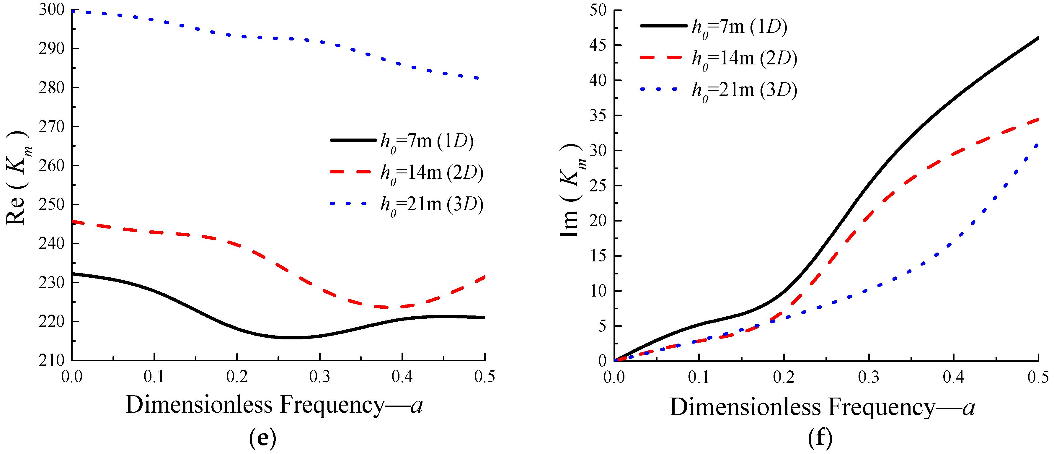
3.1.1. Effects of Rock-Socketed Depth on Dynamic Impedance of Monopile

For case 1, three different rock-socketed depths, with elastic modulus of overlying soil Es = 30 MPa, are used to calculate Κh, Κmh, and Κm, as shown in Figure 5.
The total depth of the soil layer plus h0 always remains unchanged (equal to 5D, refer to Figure 2), which means the thickness of the upper soil layer increases while the rock-socketed depth decreases.
It can be seen from Figure 5 that the stiffness (real part of impedance) of monopile increases with the increase of rock-socketed depth, and the stiffness is frequency dependent, among which the horizontal stiffness has the lowest sensitivity to frequency. When the rock-socketed depth increases from 1D to 2D, Re(Kh), Re ( K m h ) , and Re ( K m ) increase by about 35.5%, 19.6%, and 5.6%, respectively; when the rock-socketed depth increases from 1D to 3D, the above physical quantities increase by about 148.6%, 97.3%, and 31.1%, respectively. It can be seen that the deeper the monopile is embedded in the rock, the more obvious the effect of the rock on increasing the stiffness will be.
The radiative damping of monopile decreases with the increase of rock-socketed depth, that is, the deeper the monopile is embedded in the rock, the smaller the radiative damping will be. There is a small fluctuation at low dimensionless frequencies. When the rock-socketed depth increases from 1D to 2D, c H , c M H , and c M decrease by about 31.2%, 54.1%, and 19.7%, respectively; when the rock-socketed depth increases from 1D to 3D, the above physical quantities decrease by about 74.4%, 58.0%, and 43.5%, respectively, and the horizontal damping decreases greatly. This may be due to the fact that the deeper the monopile is embedded in the rock, the smaller the interface between soil and monopile will be, and less energies will be radiated from the interface.

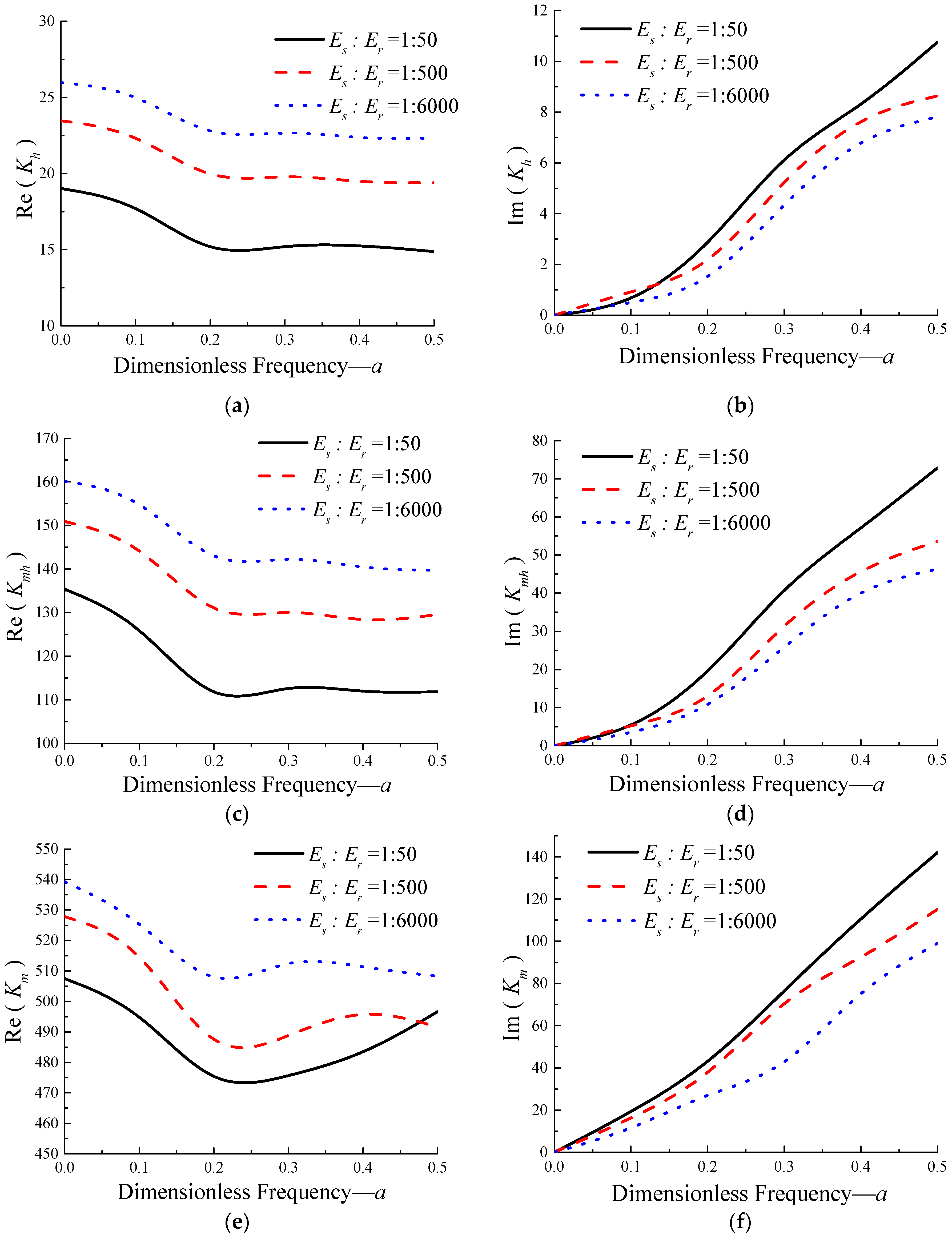
3.1.2. Influence of Elastic Modulus Ratio of Rock to Soil

Under the condition of retaining rock-socketed depth being 1D and elastic modulus of overlying soil being 10 MPa, the elastic modulus ratio of rock to soil is changed by changing the elastic modulus of rock under three different weathering conditions. The results are shown in Figure 6.
As can be seen from the figures, with the change of the elastic modulus ratio of soil and rock from 1:6000 to 1:50, the weathering degree of rock increases, and the elastic modulus of rock is closer to that of soil, so the dynamic stiffness of monopile decreases accordingly. When the elastic modulus of rock decreases to 1/12 of the original one, Re(Kh), Re ( K m h ) , and Re ( K m ) decrease by about 11.9%, 7.7%, and 3.2%, respectively; when it decreases to 1/120, Re(Kh), Re ( K m h ) , and Re ( K m ) decrease by about 31.3%, 19.6%, and 5.6%, respectively, among which the horizontal dynamic stiffness decreases the most.
The variation of radiative damping of monopile is opposite to that of dynamic stiffness. With the decrease of rock modulus, the ability of rock to reduce the dissipated energies becomes weaker, leading to an increase of radiative damping. When the elastic modulus of rock decreases to 1/12 of the original one, c H , c M H , and c M increase by about 39.5%, 27.8%, and 40.9%, respectively; and when it decreases to 1/120 of the original one, c H , c M H , and c M increase by about 44.0%, 55.2%, and 62.9%, respectively, with c M increasing the most.
In conclusion, the influence of rock-socketed depth on dynamic impedances of monopile foundation is greater than that of the elastic modulus ratio of rock to soil. A reasonable rock-socketed depth can not only effectively increase the dynamic impedance of pile foundation, but also save piling costs.

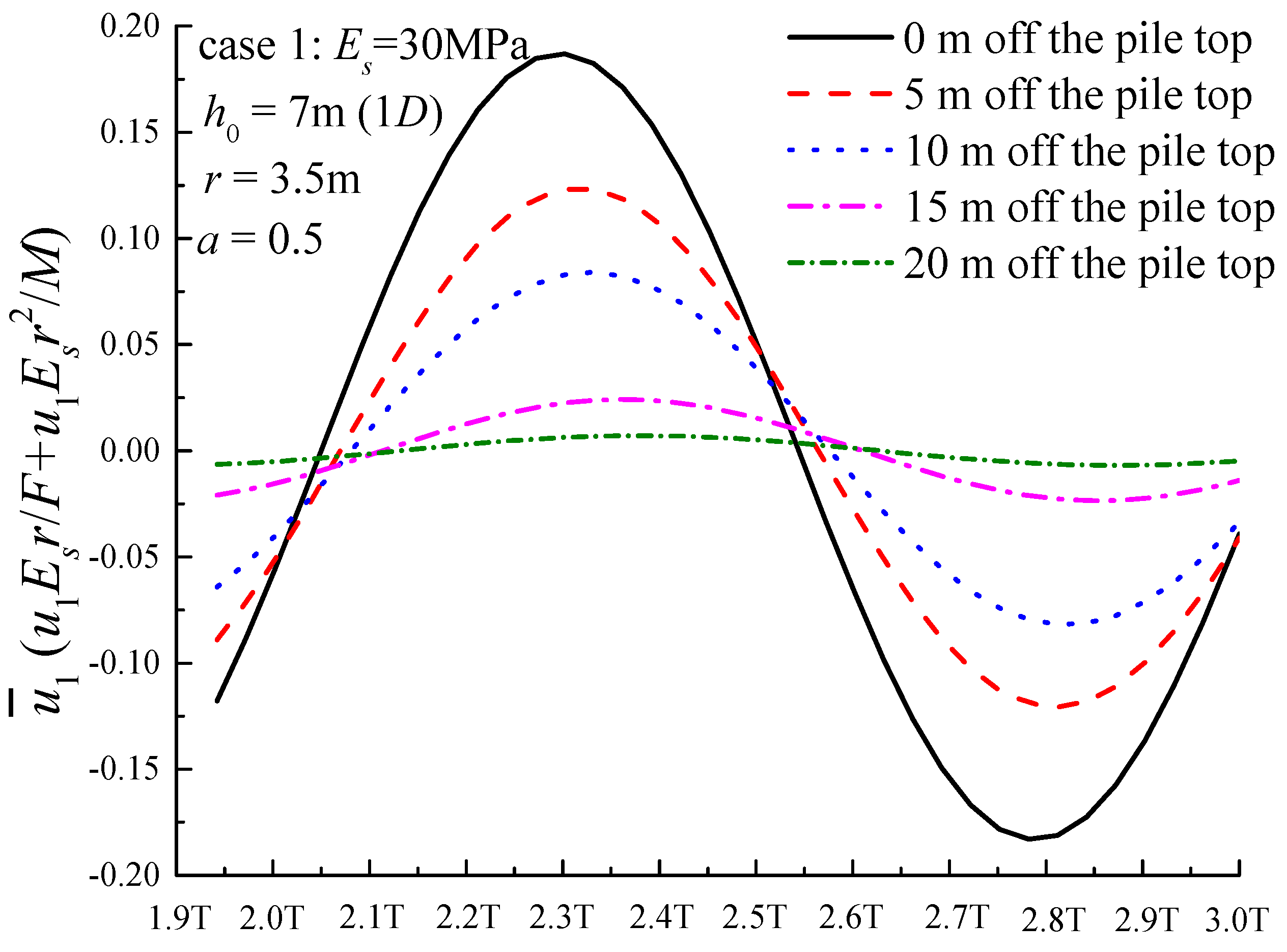
3.2. Analysis of Pile Deformation Under Simple Harmonic Horizontal Forces

When the monopile is subjected to horizontal load, the main deformation is the horizontal deflection. The displacements along the monopile also change periodically under the action of horizontal harmonic load. The dynamic response of the pile in the last period of the total calculation time (2T~3T, T = 2π/ω) is basically stable. Five measuring points (with the polar coordinate θ = π ) were arranged 0 m, 5 m, 10 m, 15 m, and 20 m away from the top of the pile, whose dimensionless deflections under horizontal load and bending moment ( u 1 ¯ = u 1 E s r / F + u 1 E s r 2 / M ) in the last calculation period were extracted and plotted in Figure 7. The figure shows that the time when the displacement amplitude of each point reaches its maximum is almost the same. Therefore, it will be fast and effective to draw the deformation curve of monopile if we extract the displacement of points along the monopile from the analysis step, in which the displacement of pile top reaches its maximum.

3.2.1. Effect of Dimensionless Frequency on Monopile Deformation

The results of pile deflection under horizontal load and bending moment when rock-socketed depth is 1D are shown in Figure 8. Z means the distance from the calculated point to ground. When the dimensionless frequency changes from 0 to 0.5, the deformation of points along the pile in the upper soil layer firstly increases and then decreases, being the smallest under the action of static force, and the largest (about 1.28 times that of the smallest) when a = 0.2. The deflection at the bottom of the monopile is very small, as shown in Figure 9, due to the fastening effect of rock on monopile.

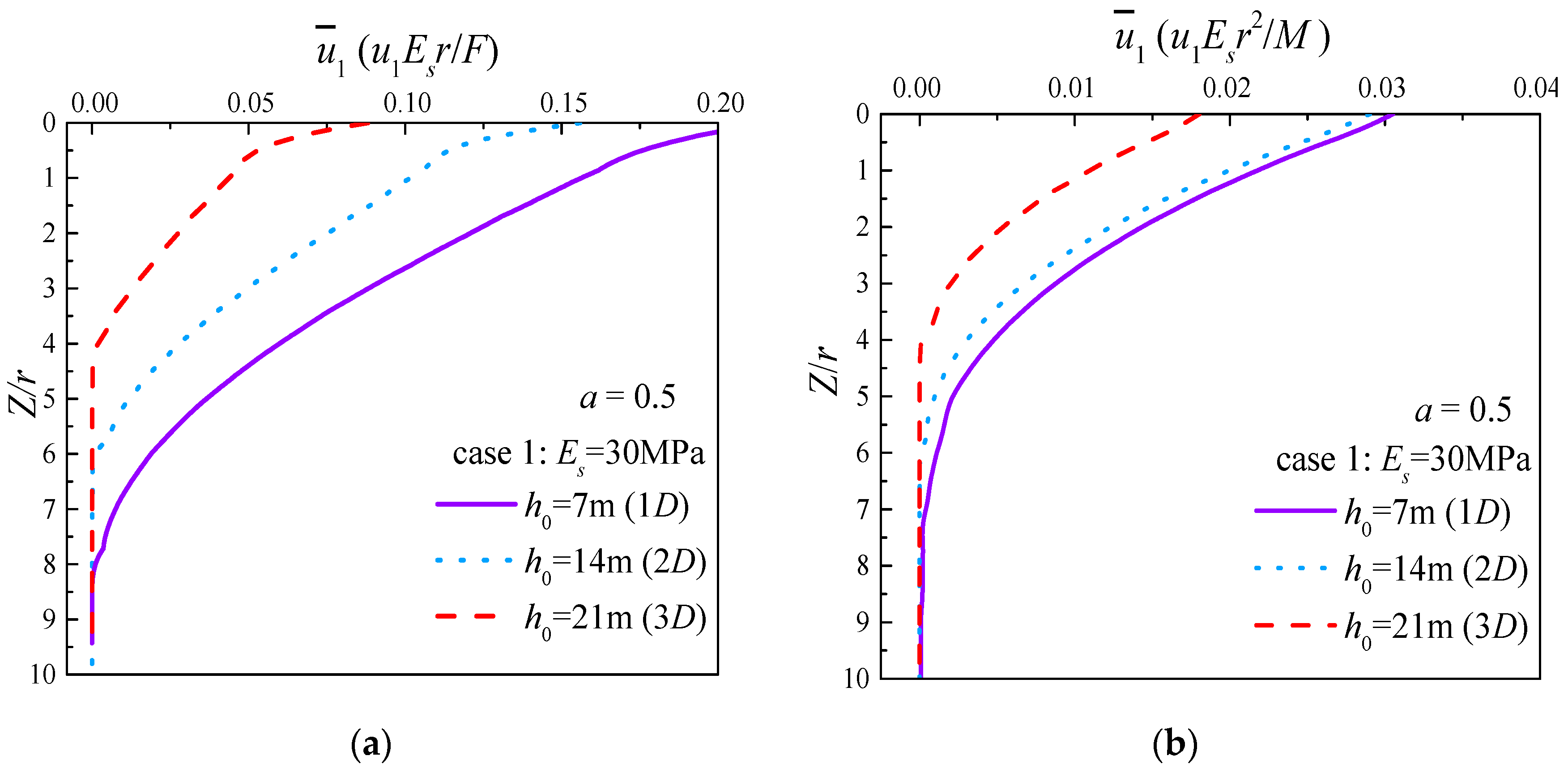
3.2.2. Effect of Rock-Socketed Depth on Pile Deformation

The deformation curves of monopile under different socketed depth conditions are shown in Figure 10. With the increase of rock-socketed depth, the deflection of monopile decreases within the soil layer. When h0 increases from 1D to 2D, the deflection of pile top decreases about 9.6%, and 46.6% when it increases from 1D to 3D. The pile deflection gradually decreases to almost 0 near the interface of rock and soil. While the slight reverse deformation exists, when h0 is 1D and 2D in the rock layer, it disappears when the pile is embedded deeper in the rock.

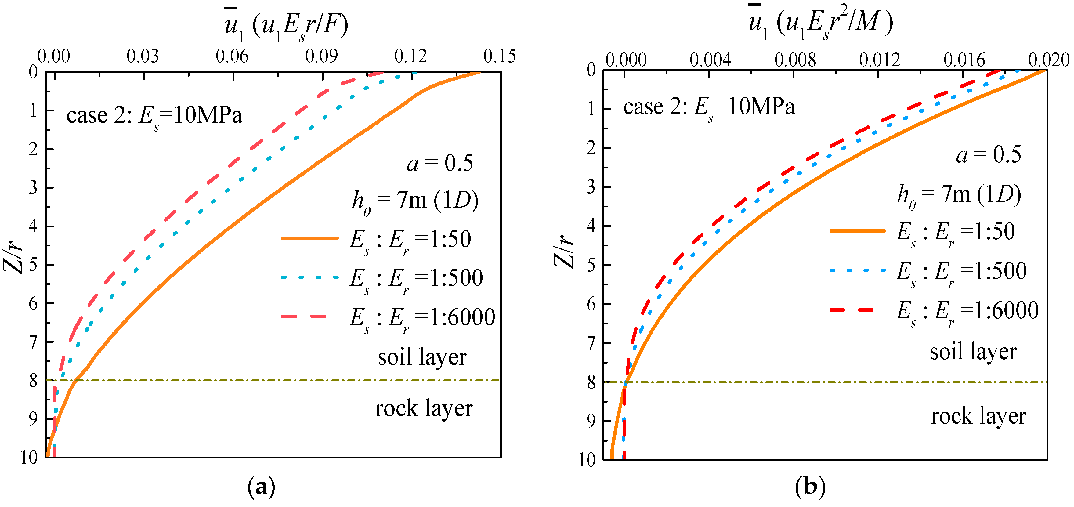
3.2.3. Effect of Elastic Modulus Ratio Between Soil and Rock on Monopile Deformation

Figure 11 shows the deformation of monopile gradually increases as the elastic modulus of rock decreases. When the monopile is embedded in slightly weathered rock, the point where deflection of the pile becomes 0 is still near the interface of soil and rock, with a small deformation of pile part embedded in rock. However, the point moves downward with an obvious deformation in the lower part of the pile as the rock is completely weathered, which indicates that the effect the rock has on fastening the pile is weakened. Viewed from the range of curve changing, the influence of rock-socketed depth on pile deformation is slightly greater than that of the elastic modulus ratio between soil and rock.

3.3. Analysis of the Internal Force of Pile under Simple Harmonic Forces

In this part, von-Mises stress along the monopile is extracted from the analysis step in which the displacement of pile reaches the maximum, to analyze the influences of different rock-socket depth and elastic modulus ratio between soil and rock. From the five measuring points in the previous section, it can be seen that when the displacement of the pile reaches its maximum, the corresponding dimensionless stress ( σ M ¯ = σ M r 2 / F + σ M r 3 / M ) are also approximately at the maximum (Figure 12).

3.3.1. Effect of Dimensionless Frequency on von-Mises Stress of Pile

Dimensionless von-Mises stresses at points along monopile are taken when h0 = 1D. The results are shown in Figure 13. Stress of the pile first increases and then decreases with the increase of dimensionless frequency, reaching the maximum, when a = 0.2, in this case. At the interface of rock and soil, the stress of monopile changes very sharply: the stress of the pile under the interface is far less than that in the upper soil layer. Stress of the socketed part decreases rapidly, close to zero at the bottom of the pile.

3.3.2. Effect of Rock-Socketed Depth on Von-Mises Stress

To study the effect of rock-socketed depth on von-Mises stress, the results are extracted when a = 0.5, as shown in Figure 14. The stress of pile in the soil layer increases with the increase of rock-socketed depth, and von-Mises stresses for monopile in the soil layer part are much larger than monopile in the rock layer part. The stress has a sudden drop near the interface between soil and rock, and decreases sharply in the rock, tending to zero at the bottom of pile.

3.3.3. Effect of Elastic Modulus Ratio between Soil and Rock on Von-Mises Stress

The von-Mises stresses in Figure 15 are also extracted under the condition that a = 0.5, h0 = 1D. With the increase of rock weathering degree, the stress of monopile in the upper soil layer part decreases while it increases in the lower rock layer part. The drop of stress near the interface under strong weathering rock condition is gentler than the weak weathering rock condition.

4. Conclusions and Outlook

4.1. Basic Conclusions

Based on a combined finite–infinite element model, the dynamic impedances and dynamic responses of large diameter rock-socketed monopiles under harmonic load are analyzed in this paper. The conclusions are as follows:
(1)
When rock-socketed depth increases:
  • the dynamic stiffness of pile increases, while the sensitivity to dimensionless frequency decreases, indicating that the ability of pile to resist deformation increases under dynamic load, which is consistent with the results obtained from monopile deformation analysis;
  • the radiative damping of pile decreases, and the horizontal radiative damping decreases the most. When the contact surface between the pile and the soil becomes smaller, less stress wave energies will be generated and radiated;
  • the deformation of monopile reduces and the deformation of the rock-embedded part of the monopile is very small;
  • von-Mises stress of the monopile in the soil layer increases, and there is a sudden drop at the soil–rock interface.
(2)
When the elastic modulus ratio of soil to rock increases, that is, the weathering degree of rock increases:
  • the dynamic stiffness of the monopile reduces, and the closer the elastic modulus of rock is to that of soil, the faster its reduction rate is. When the elastic modulus of the rock is reduced, resulting in the weakened ability of the pile to resist deformation under external force;
  • the radiative damping increases, with the rotational radiative damping increasing the most. Compared with rock, it seems that the capability of the soil to radiate stress waves is stronger;
  • the deflection of the monopile increases and the point at which the displacement is 0 shifts downward, considering that the effect of rock on fastening the pile is reduced;
  • von-Mises stress of monopile in the soil layer decreases while increasing in the rock layer. The phenomenon of stress drop at the soil–rock interface is no longer obvious.
Besides, with the dynamic impedances obtained in this study, the resonant frequencies and dynamic responses of the offshore wind turbines can be calculated by the so-called substructure technique [33,34].

4.2. Outlook on Further Study

Due to the assumptions made for the model, there are still limitations in the research. Some differences may exist between the homogeneous constitutive model of rock and soil and the geological conditions in practical engineering. In addition, the finite element method can not be used to discover the dynamic impedance evolution of monopile under long periodic vibration loads. More work remains to solve:
(1)
The deformation and stress of the soil/rock around monopile under dynamic loadings with different amplitudes can be analyzed, in order to know more about the soil-rock-monopile dynamic contact problem;
(2)
The dynamic impedances and responses of rock-socketed monopile under long-term alternating loads remain to be further studied in the future;
(3)
More complicated soil and rock models can be further used to study the dynamic responses of rock-socketed monopiles under extreme loading conditions.

Author Contributions

Conceptualization, R.H.; Software, J.J. and Z.G.; Supervision, J.Z.; Validation, W.P.; Visualization, Z.S.; Writing—original draft, J.J. and R.H.; Writing—review & editing, R.H., J.J., J.Z. and Z.G.

Funding

The first author would like to acknowledge the support of the National Natural Science Foundation of China, Grant No. 51879097 and the Fundamental Research Funds for the Central Universities, Grant No. 2018B12714.

Conflicts of Interest

The authors declare no conflict of interest. Rui He, Ji Ji, Jisheng Zhang, Wei Peng, Zufeng Sun and Zhen Guo.

References

  1. Wen, M.; Wu, B.; Lin, X.; You, L.; Yang, L. Distribution characteristics and assessment of wind energy resources at 70 m height over Fujian coastal areas. Resour. Sci. 2011, 33, 1346–1352. [Google Scholar]
  2. Chen, W.Y.; Chen, G.X.; Chen, W.; Liao, C.C.; Gao, H.M. Numerical simulation of the nonlinear wave-induced dynamic response of anisotropic poro-elastoplastic seabed. Mar. Georesour. Geotechnol. 2018, 1–12. [Google Scholar] [CrossRef]
  3. Guo, Z.; Jeng, D.S.; Zhao, H.Y.; Guo, W.; Wang, L.Z. Effect of Seepage Flow on Sediment Incipient Motion around a Free Spanning Pipeline. Coast. Eng. 2019, 143, 50–62. [Google Scholar] [CrossRef]
  4. Li, K.; Guo, Z.; Wang, L.Z.; Jiang, H.Y. Effect of Seepage Flow on Shields Number around a Fixed and Sagging Pipeline. Ocean Eng. 2019, 172, 487–500. [Google Scholar] [CrossRef]
  5. Qi, W.G.; Li, Y.X.; Xu, K.; Gao, F.P. Physical modelling of local scour at twin piles under combined waves and current. Coast. Eng. 2019, 143, 63–75. [Google Scholar] [CrossRef]
  6. Zhao, H.Y.; Jeng, D.S.; Liao, C.C.; Zhou, J.F. Three-dimensional modeling of wave-induced residual seabed response around a mono-pile foundation. Coast. Eng. 2017, 128, 1–21. [Google Scholar] [CrossRef]
  7. Ke, W.; Fan, Q.; Jing, Z. Insight into Failure Mechanism of Large-Diameter Monopile for Offshore Wind Turbines Subjected to Wave-Induced Loading. J. Coast. Res. 2015, 73, 554–558. [Google Scholar]
  8. Liao, C.; Chen, J.; Zhang, Y. Accumulation of pore water pressure in a homogeneous sandy seabed around a rocking mono-pile subjected to wave loads. Ocean Eng. 2019, 173, 810–822. [Google Scholar] [CrossRef]
  9. Arany, L.; Bhattacharya, S.; Macdonald, J.; Hogan, S.J. Design of monopiles for offshore wind turbines in 10 steps. Soil Dyn. Earthq. Eng. 2017, 92, 126–152. [Google Scholar] [CrossRef] [Green Version]
  10. Rackwitz, F.; Savidis, S.; Tasan, E. New Design Approach for Large Diameter Offshore Monopiles Based on Physical and Numerical Modelling. Am. Soc. Civ. Eng. 2012, 356–365. [Google Scholar]
  11. Jonkman, J.; Butterfield, S.; Passon, P.; Larsen, T.J.; Camp, T.; Nichols, J.; Azcona, J.; Martinez, A. Offshore Code Comparison Collaboration within IEA Wind Annex XXIII: Phase II Results Regarding Monopile Foundation Modeling; Office of Scientific & Technical Information Technical Reports; European Wind Energy Association: Brussels, Belgium, 2010. [Google Scholar]
  12. Frontier Technology. Longyuan Electric Power Successfully Implemented Construction of the World’s First “Implanted” Rock-Socketed Monopile Foundation. Available online: http://www.souhu.com/a/201123560_99902347 (accessed on 30 October 2017).
  13. Byrne, B.; Mcadam, R.; Burd, H.J.; Houlsby, G.T.; Martin, C.M.; Beuckelaers, W.J.A.P. PISA: New Design Methods for Offshore Wind Turbine Monopiles. In Proceedings of the 8th International Conference for Offshore Site Investigation and Geotechnics, London, UK, 12–14 September 2017; Volume 1, pp. 142–161. [Google Scholar]
  14. He, R.; Wang, L.Z. Elastic rocking vibration of an offshore Gravity Base Foundation. Appl. Ocean Res. 2016, 55, 48–58. [Google Scholar] [CrossRef]
  15. Harte, M.; Basu, B.; Nielsen, S.R.K. Dynamic analysis of wind turbines including soil-structure interaction. Eng. Struct. 2012, 45, 509–518. [Google Scholar] [CrossRef]
  16. Damgaard, M.; Bayat, M.; Andersen, L.V. Assessment of the dynamic behavior of saturated soil subjected to cyclic loading from offshore monopile wind turbine foundations. Comput. Geotech. 2014, 61, 116–126. [Google Scholar] [CrossRef]
  17. Leblanc, C. Design of Offshore Wind Turbine Support Structures. Ph.D. Thesis, Aalborg University, Aalborg, Denmark, January 2009. [Google Scholar]
  18. Lombardi, D.; Bhattacharya, S.; Wood, D.M. Dynamic soil structure interaction of monopile supported wind turbines in cohesive soil. Soil Dyn. Earthq. Eng. 2013, 49, 165–180. [Google Scholar] [CrossRef]
  19. Andersen, L.V.; Vahdatirad, M.J.; Sichani, M.T. Natural frequencies of wind turbines on monopile foundations in clayey soils A probabilistic approach. Comput. Geotech. 2012, 43, 1–11. [Google Scholar] [CrossRef]
  20. Liao, W.M.; Zhang, J.J.; Wu, J.B. Response of flexible monopile in marine clay under cyclic lateral load. Ocean Eng. 2017, 147, 89–106. [Google Scholar] [CrossRef]
  21. Achmus, M.; Kuo, Y.S.; Abdel-Rahman, K. Behavior of monopile foundations under cyclic lateral load. Comput. Geotech. 2009, 36, 725–735. [Google Scholar] [CrossRef]
  22. Abadie, C.N. Cyclic Lateral Loading of Monopile Foundations in Cohesionless Soils. Ph.D. Thesis, University of Oxford, Oxford, UK, March 2015. [Google Scholar]
  23. Liu, R.; Zhou, L.; Lian, J.J.; Ding, H.Y. Behavior of Monopile Foundations for Offshore Wind Farms in Sand. J. Waterw. Port Coast. Ocean Eng. 2016, 142, 04015010. [Google Scholar] [CrossRef]
  24. Hokmabadi, A.S.; Fakher, A.; Fatahi, B. Full scale lateral behavior of monopiles in granular marine soils. Mar. Struct. 2012, 29, 198–210. [Google Scholar] [CrossRef]
  25. Omer, J.R.; Robinson, R.B.; Delpak, R. Large-scale pile tests in Mercia mud stone: Data analysis and evaluation of current design methods. Geotech. Geol. Eng. 2003, 21, 167–200. [Google Scholar] [CrossRef]
  26. He, R.; Kaynia, A.M.; Zhang, J.S. A poroelastic solution for dynamics of laterally loaded offshore monopiles. Ocean Eng. 2019, 179, 337–350. [Google Scholar] [CrossRef]
  27. He, R.; Kaynia, A.M.; Zhang, J.S.; Chen, W.Y.; Guo, Z. Influence of vertical shear stresses due to pile-soil interaction on lateral dynamic responses for offshore monopiles. Mar. Struct. 2019, 64, 341–359. [Google Scholar] [CrossRef]
  28. He, R.; Pak, R.Y.S.; Wang, L.Z. Elastic lateral dynamic impedance functions for a rigid cylindrical shell type foundation. Int. J. Numer. Anal. Methods Geomech. 2017, 41, 508–526. [Google Scholar] [CrossRef]
  29. Liu, T.L.; Wu, W.B.; Dou, B.; Jang, G.S.; Lv, S.H. Vertical dynamic impedance of pile considering the dynamic stress diffusion effect of pile end soil. Mar. Geotechnol. 2017, 35, 8–16. [Google Scholar] [CrossRef]
  30. Bhattacharya, S.; Nikitas, N.; Garnsey, J. Observed dynamic soil structure interaction in scale testing of offshore wind turbine foundations. Soil Dyn. Earthq. Eng. 2013, 54, 47–60. [Google Scholar] [CrossRef]
  31. Zhang, M.; Shang, W.; Wang, X. Lateral dynamic analysis of single pile in partially saturated soil. Eur. J. Environ. Civ. Eng. 2017, 1–22. [Google Scholar] [CrossRef]
  32. Rajapakse, R.K.; Shah, A.H. On the lateral harmonic motion of an elastic bar embedded in an elastic half-space. Int. J. Solids Struct. 1987, 23, 287–303. [Google Scholar] [CrossRef]
  33. Clough, R.W.; Penzien, J.; Griffin, D.S. Dynamics of Structures; McGraw-Hill: New York, NY, USA, 1975; ISBN 978-0-07011-392-3. [Google Scholar]
  34. He, R. Dynamic responses of offshore wind turbines on bucket foundations in sand considering soil-structure interaction. In Proceedings of the 27th International Ocean and Polar Engineering Conference, San Francisco, CA, USA, 25–30 June 2017. [Google Scholar]
Figure 1. Part of the coast of China (from OpenStreetMap).
Jmse 07 00134 g001
Figure 2. Illustration of the rock-socketed monopile.
Jmse 07 00134 g002
Figure 3. Combined finite element and infinite element model for the dynamic interaction problem.
Jmse 07 00134 g003
Figure 4. Model Verification: (a) comparison of horizontal dynamic impedance (Κh); (b) comparison of coupled dynamic impedance (Κmh); (c) comparison of rotational dynamic impedance (Κm).
Jmse 07 00134 g004
Figure 5. Effects of rock-socketed depth on dynamic impedance of monopile: (a) variation of Re(Κh) for various h0; (b) variation of Im(Κh) for various h0; (c) variation of Re(Κmh) for various h0; (d) variation of Im(Κmh) for various h0; (e) variation of Re(Κm) for various h0; (f) variation of Im(Κm) for various h0.
Jmse 07 00134 g005aJmse 07 00134 g005b
Figure 6. Effects of elastic modulus ratio of rock to soil on dynamic impedance of monopile: (a) variation of Re(Κh) for various Es to Er ratio; (b) variation of Im(Κh) for various Es to Er ratio; (c) variation of Re(Κmh) for various Es to Er ratio; (d) variation of Im(Κmh) for various Es to Er ratio; (e) variation of Re(Κm) for various Es to Er ratio; (f) variation of Im(Κm) for various Es to Er ratio.
Jmse 07 00134 g006
Figure 7. The sinusoidal curves of monopile deflection.
Jmse 07 00134 g007
Figure 8. Effect of dimensionless frequency on monopile deflection.
Jmse 07 00134 g008
Figure 9. The magnified view of the rock-embedded part of monopile.
Jmse 07 00134 g009
Figure 10. Effect of rock-socketed depth on monopile deformation: (a) deflection of monopile under pure horizontal load; (b) deflection of monopile under pure bending moment.
Jmse 07 00134 g010
Figure 11. Effect of elastic modulus ratio between soil and rock on pile deformation: (a) deflection of monopile under pure horizontal load; (b) deflection of monopile under pure bending moment.
Jmse 07 00134 g011
Figure 12. The periodic change in von-Mises stress.
Jmse 07 00134 g012
Figure 13. Effect of dimensionless frequency on von-Mises stress of monopile.
Jmse 07 00134 g013
Figure 14. Effect of rock-socketed depth on von-Mises stress: (a) von-Mises stress of monopile under pure horizontal load; (b) von-Mises stress of monopile under pure bending moment.
Jmse 07 00134 g014
Figure 15. Effect of elastic modulus ratio between soil and rock on von-Mises stress: (a) von-Mises stress of monopile under pure horizontal load; (b) von-Mises stress of monopile under pure bending moment.
Jmse 07 00134 g015
Table 1. Parameters for soil, rock, and monopile.
VariableCase 1 h0 (m)71421
Case 2 Er (GPa)0.5560
PropertiesPartsSteel pileSoilRock
Density-ρ
(kg/m3)
790015003000
Poisson’s Ration-ν0.30.30.25
Elastic Modulus-E
(MPa)
2.1 × 10⁵
Note: In case 1, Es = 30 MPa, Er = 40 GPa, Ep = 210 GPa, variable: h0; In case 2, Es = 10 MPa, Ep = 210 GPa, h0 = 7 m, variable: Er.

