1. Introduction
The flapping of wings and tails are common and have inspired several researchers to carry out experiments to understand the behavior of the flapping motion in a fluid. Several kinds of research have been done in the past for ship propulsion using wave energy [
1,
2]. The hydrofoils were attached to the ship through an elastic system, so that the hydrofoil can oscillate in the heave and pitch directions to effectively generate the thrust force against the wave propagation.
Wu [
3] introduced a two-dimensional hydrofoil that can extract energy by oscillating through waves in water. It was found that energy can be extracted only when the wave had a vertical velocity component to the hydrofoil span and if the flow was uniform, energy could not be extracted. Finally, the best mode of heave and pitching for extraction of wave energy by passive type wave devouring propulsor was obtained.
Later, Wu’s theory of an oscillating hydrofoil was extended by including a free surface effect to study the passively flapping hydrofoil, famously known as wave devouring propulsion [
4,
5]. Extensive experimental work on the pure pitch and pure heave with NACA 0015 can be found in [
6]. Further, heave and pitch motions were combined for NACA 0012 and the performance of flapping foil propulsion were experimentally studied [
7]. Subsequently, the effects of angle of attack on the flapping foil propulsion were reported [
8]. Studies show that the explicit control of the angle of attack in flapping foil propulsion can broadly increase thrust force and efficiency. The application of flapping foil for maneuvering was also reported [
9]. It was found that by adding pitch bias to the harmonic motion, large lift force can be achieved. Also, flapping foil as an auxiliary propulsor near the free surface was reported [
10,
11]. Recently, passive flapping foils and plates were installed around a floater to investigate the stationkeeing using wave energy experimentally [
12]. This report showed that the passive flapping system was very effective in long and mid waves, however, in short waves, passive flapping system could not keep the floater in the allowable drift limit. Probably the energy extracted by the flapping system in short waves was not enough to keep the position of the floater and external energy must be applied. Therefore, an investigation of the active mode of a flapping system becomes important.
For the past few years, due to technical advancements in the field of computational fluid dynamics (CFD), the numerical analysis has become more realistic and can be done in a reasonable time frame. Also, CFD can be coupled with the computational structural mechanics (CSM) to simulate several multi-physics problems such as fluid-structure interaction (FSI). In recent years, FSI simulations have been conducted to evaluate the environmental loads and dynamic response of the offshore structures [
13,
14,
15] and many aerodynamic [
16,
17] and biomedical applications [
18,
19].
The purpose of this study was to investigate the possibilities of using flapping foils for designing a station-keeping system of a floater in short waves. In order to do that, the evaluation and comparison of thrust forces of each foil in active and passive modes were necessary. In the passive mode, the flapping of hydrofoil was governed by the incoming waves, therefore, thrust extents could not be controlled by flapping frequencies, there were the other means to do it. However, in the active mode, hydrofoil was driven by an electric motor that could generate various flapping frequencies, therefore, a controller must be designed to effectively operate the flapping frequencies of hydrofoil to meet the station-keeping goals. In order to do that, thrust forces must be estimated for each operating motor frequency in short waves and still water conditions. Therefore, in this study, a flapping foil was set to oscillate at a fixed location and the thrust forces were evaluated for the active mode of flapping foil in still water and short waves for five operating flapping frequencies. Also, the CFD model was validated by comparing the thrust forces generated by fixed foil and passive flapping foil.
2. Methodology
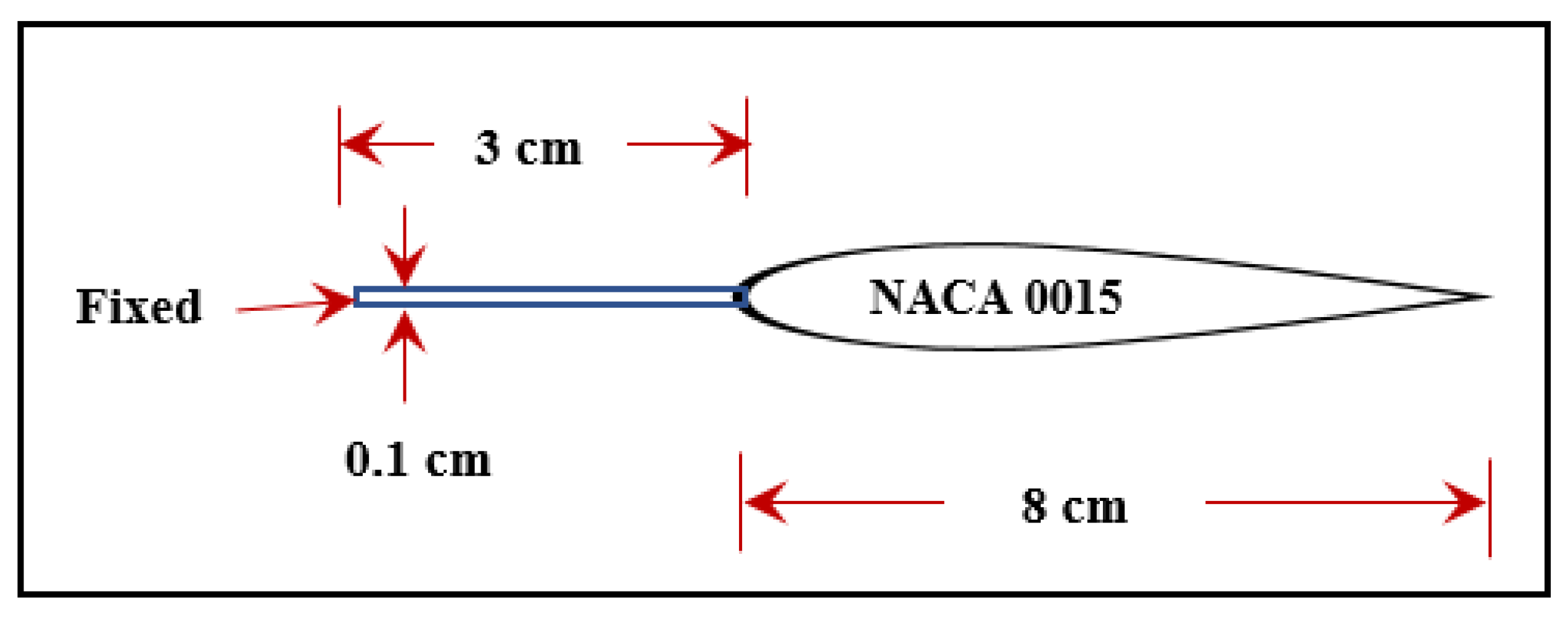
This paper aimed to analyze the fluid-structure interaction of a horizontally placed active flapping foil in short waves. A rigid NACA 0015 section of 8 cm chord length, made of acrylic glass was attached from its leading edge to the 0.1 cm thick high-density polyethylene (HDPE) elastic plate as shown in
Figure 1. This arrangement of flapping foil was taken from the work reported in [
20], where an elastic plate was attached to the leading edge of the foil to guide the hydrofoil oscillate smoothly in waves.
FSI simulations for the active and passive mode of flapping foil were done using ANSYS Workbench 19.2 [
21]. Since the current version of simulation tool does not support the FSI simulation for 2-Dimensional models, 1 cm thick geometry consists of fluid and solid domain was created for the simulation. Duration of the simulation was 10 s.
2.1. Geometry
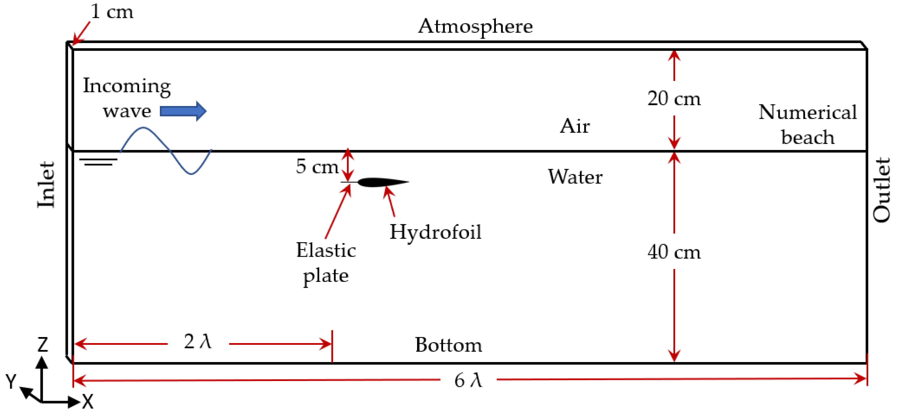
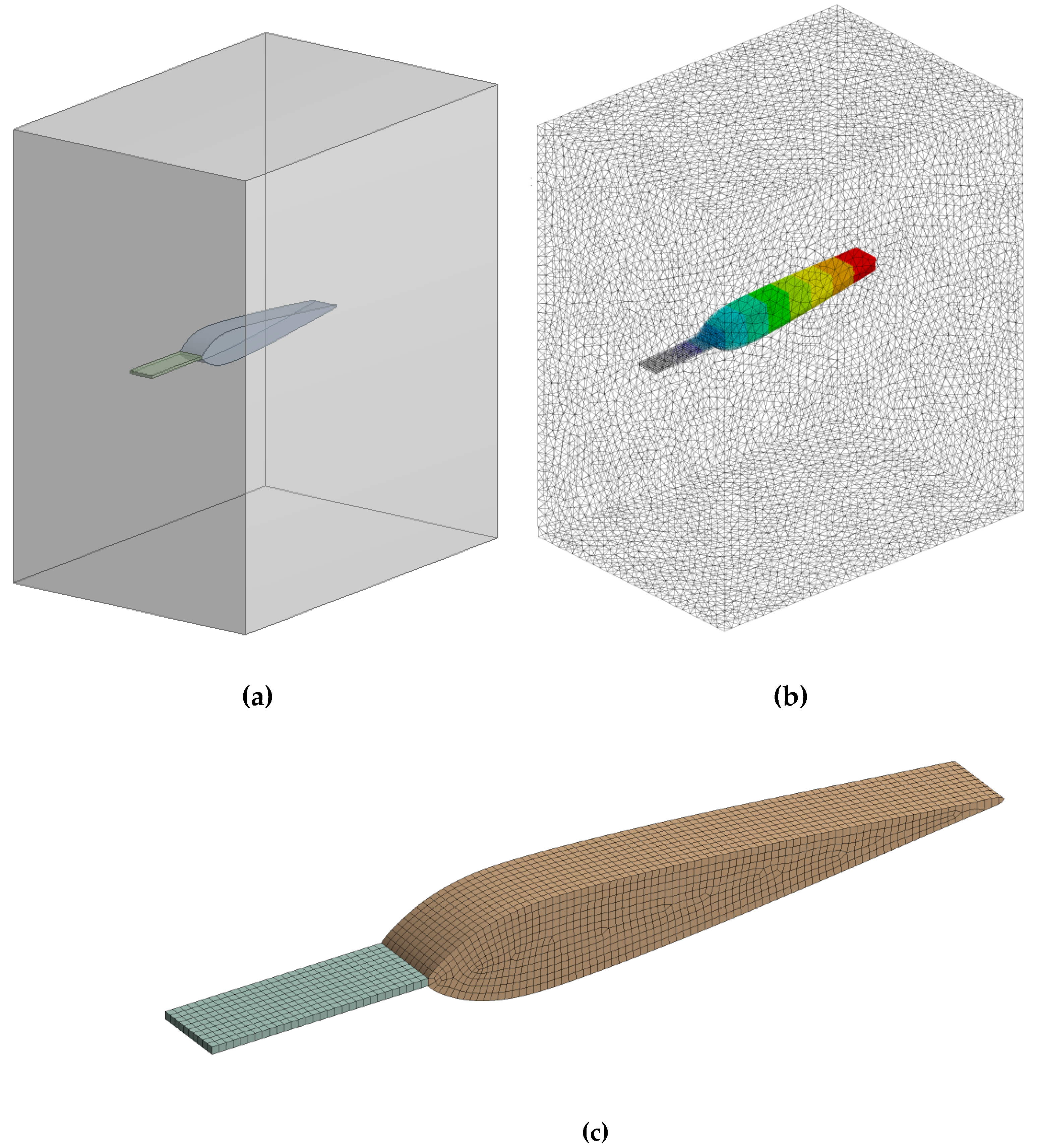
Geometrical models of both flapping foil and fluid domain were created as shown in
Figure 2. The fluid domain consists of two media (air and water). Length of the rectangle was six times that of the wavelength (λ) and the structural model was placed at 2λ distance from the inlet and 5 cm below the mean free surface line. Water depth was considered as 40 cm as shown in
Figure 2. An elastic plate (0.1 cm thick) was fixed at one end and from another end and was attached to the leading edge of the hydrofoil. The material properties of the hydrofoil and elastic plate were as acrylic glass and HDPE, respectively.
2.2. Computational Mesh
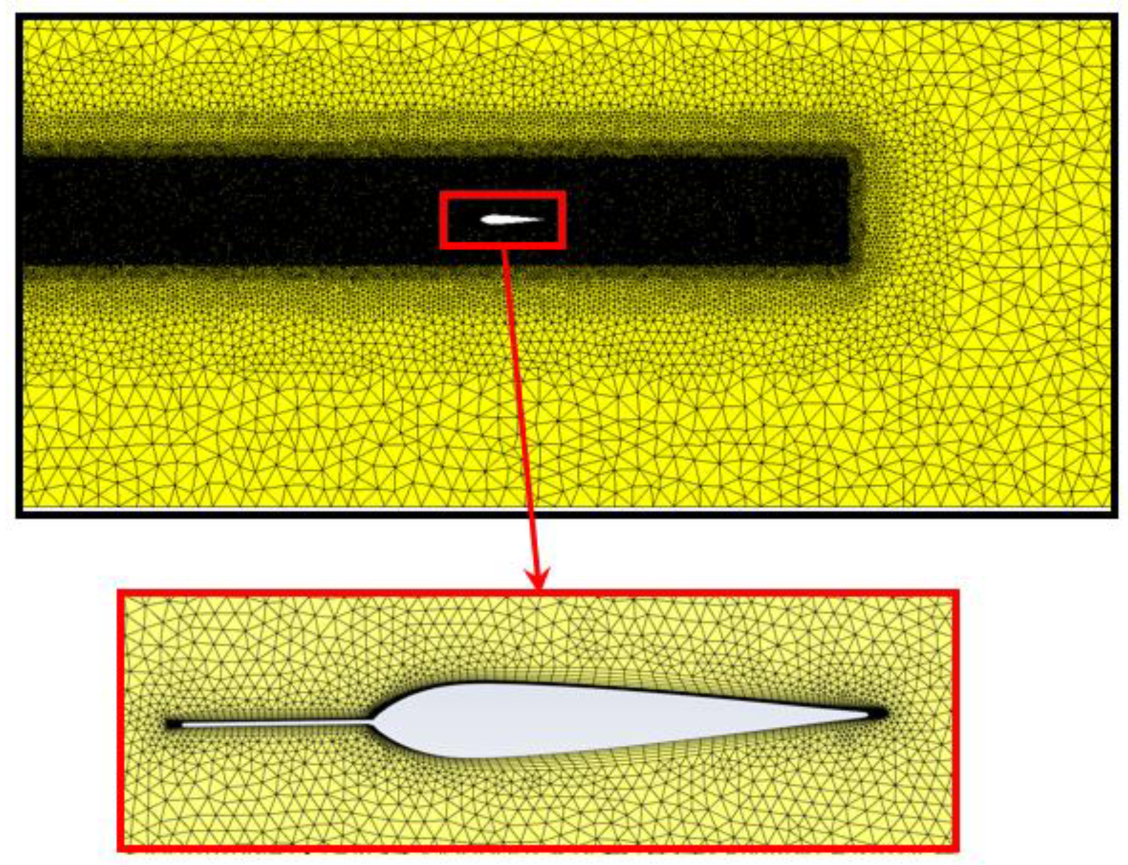
The volume of the fluid domain was formed using FLUENT Mesh. It was made up of tetrahedral cells belonging to the unstructured mesh category. A box of the very fine mesh was created from the inlet to capture the free surface and the structural deformation effectively. Also, the volume mesh of the fluid domain includes the inflation layer around the flapping foil to resolve the boundary layer effects efficiently in turbulent flow as shown in
Figure 3. The growth ratio of the inflation layer was 1.2 to maintain a slow transition of meshes. The fluid mesh contained 2.5 million cells.
2.2.1. Near Wall Treatment
In order to get a good solution for a wall under dynamic loading, the distance from the wall to the first cell was considered an important parameter, obtained from a non-dimensional number y+. The target value of y+ was evaluated from the ANSYS Fluent simulation as 1. Therefore, the first layer thickness of inflation was evaluated as 0.85 mm.
2.2.2. Structural Mesh
The volume of the solid domain was formed using Structural Mesh. It was made up of hexahedral cells belonging to the structured mesh category as shown in
Figure 4. The solid mesh contains 25 thousand cells.
2.3. Load Cases
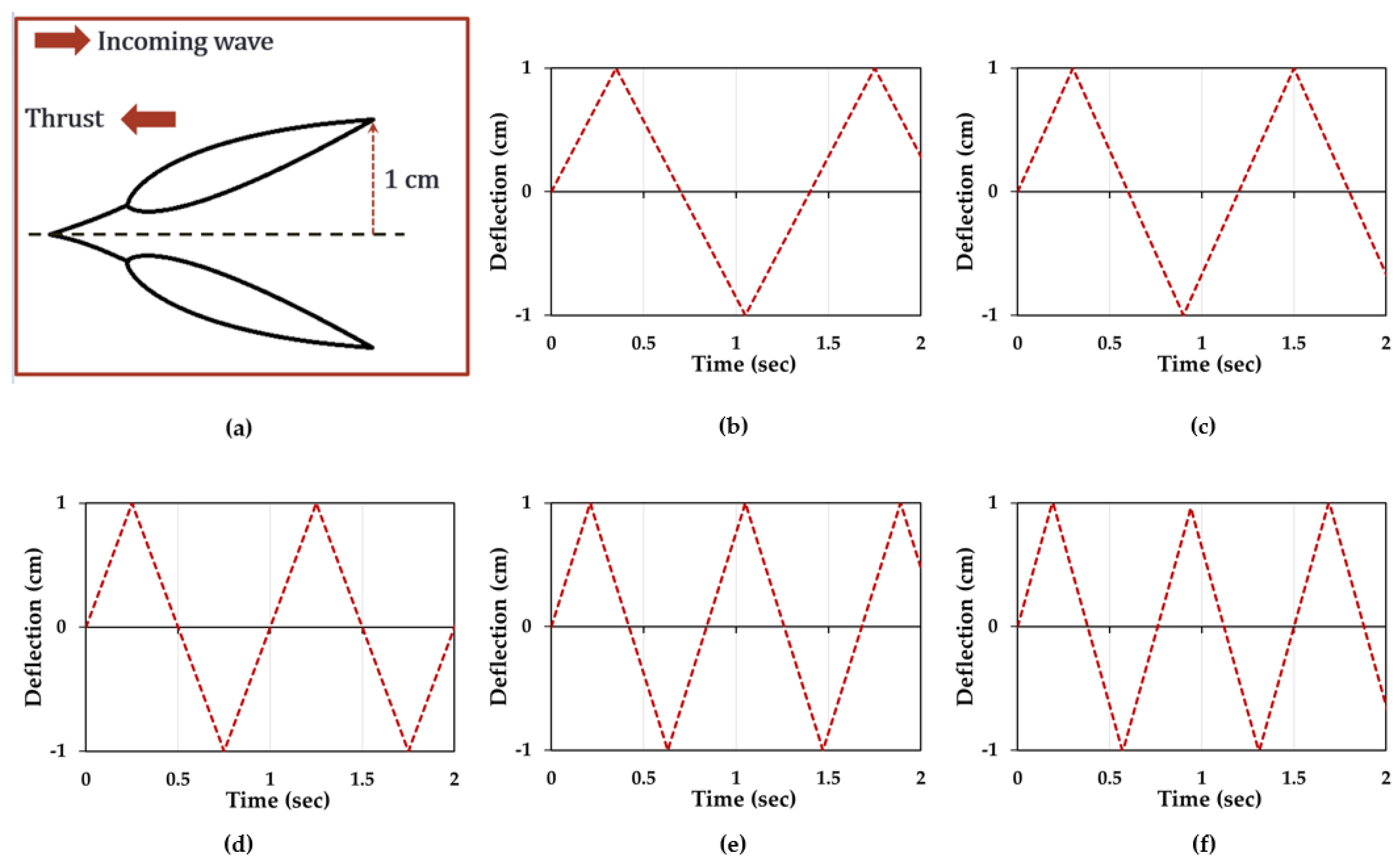
Figure 5 shows the trailing edge displacements of the active flapping foil. The frequency of the five forced flapping and wave specification were displayed in
Table 1 and
Table 2 respectively.
2.4. Modal Acoustic Analysis
Modal acoustic analysis was performed to determine the natural flapping frequency of the foil in air and water [
22] as shown in
Figure 6. It was an essential process to avoid any structural failure due to resonance.
In order to evaluate the natural frequencies of a flapping foil in air and water, an acoustic body of fluid around the flapping foil was created. The used model is shown in
Figure 6a.
Figure 6b shows the 380,000 tetrahedral mesh generated for the acoustic body and
Figure 6c shows the 10,000 hexahedral mesh generated for the solid structure. The interface of solid and acoustic body element nodes was shared to avoid contact elements. The modal acoustic analysis was performed in full damping mode. The natural period of the flapping foil was estimated as 0.15 s in air and 0.23 s in water, that was much smaller than the forced flapping frequency of the foil displayed in
Table 1.
2.5. Simulation Setup
The 2-way FSI simulation was conducted to evaluate the thrust forces due to active flapping motion of the hydrofoil in short waves.
2.5.1. Boundary Conditions
Table 3 shows the conditions applied to the boundaries of the fluid domain shown in
Figure 2.
2.5.2. FLUENT Solver Setup
Fluent uses the finite volume method to convert the general transport equation into a system of algebraic equations. The Reynolds Averaged Navier Stokes (RANS) was used to model the effects of turbulence. K-ω SST (Shear Stress Transport) turbulence model was used to effectively capture the near the wall flow and free surface flow regions as shown in
Table 4.
2.5.3. System Coupling Setup
System coupling tool was used to integrate fluid and structural solvers in FSI simulations.
Figure 7 shows how ANSYS fluid solver (FLUENT) and ANSYS solid solver (MECHANICAL) were coupled and the information transferred.
FLUENT provides information on the fluid forces acting on the body and Mechanical provides nodal displacement changes in the structure due to fluid loading and system coupling synchronize the whole setup of simulation. This type of simulation called 2-way FSI. The step size for the simulation was used as 0.0005 s.
3. Results
Thrust forces obtained for the active mode of the flapping foil in a numerically modelled 1 cm thick fluid–solid domain are shown in
Figure 3 and the end effects of the flapping foil was neglected. The span of the flapping foil was 20 cm during the experiment, therefore, all the numerically obtained results were multiplied 20 times and presented in this paper. The global forces acting on the flapping foil in the x-direction of the wave flume were considered as thrust forces. However, in the results section, the thrust forces were varying in the y-direction of the plots. The positive y-direction of the thrust plot represents the force generated against the wave direction.
3.1. Mesh Convergence
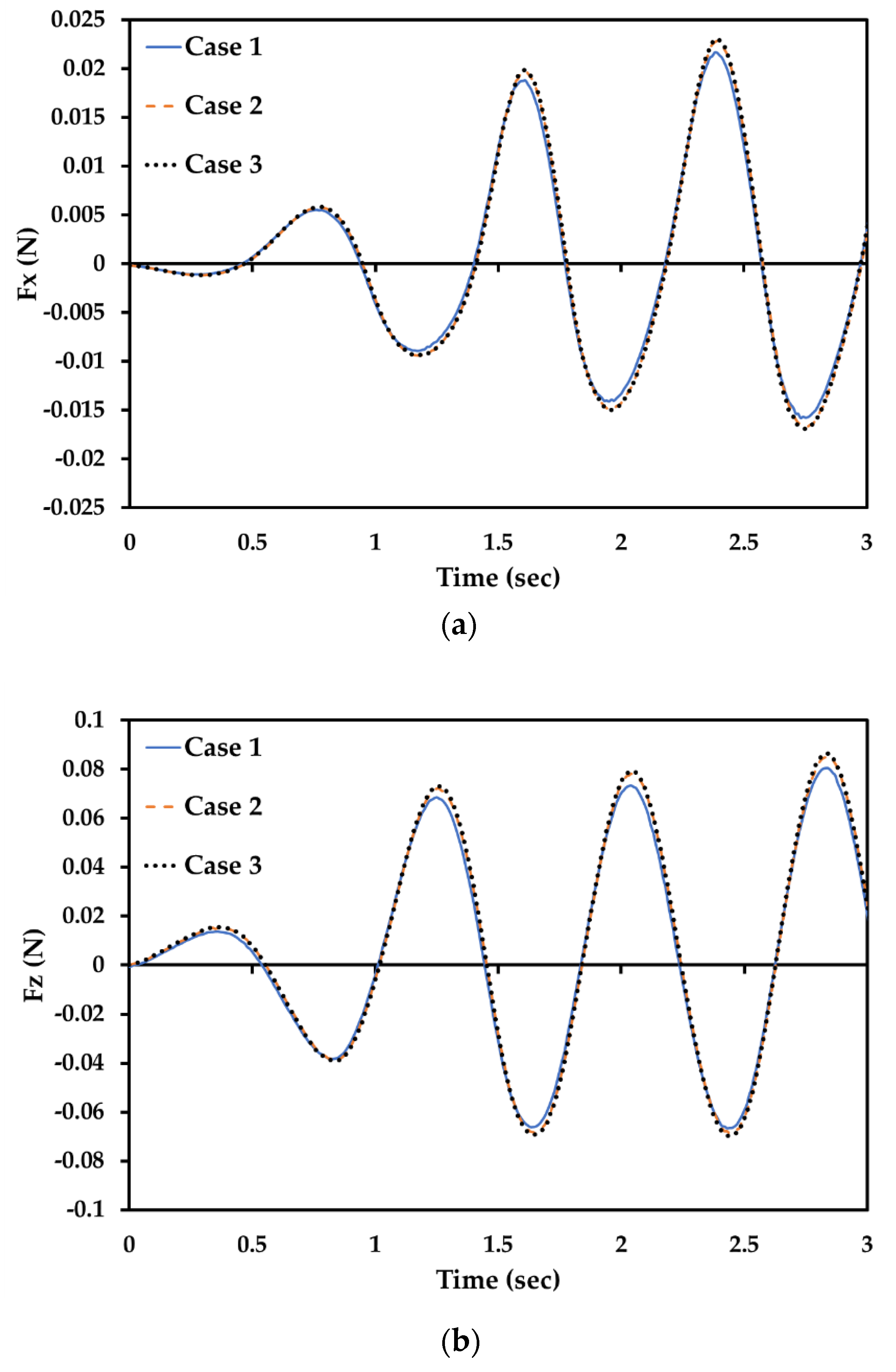
In order to perform a mesh convergence study, three mesh resolutions were created as mentioned in
Table 5. Mesh convergence check was performed in ANSYS FLUENT 19.2 by generating a regular wave. And the forces acting on the fixed foil in x and z directions were evaluated as shown in
Figure 8a,b, respectively.
Results in
Figure 8 show that case 1 was slightly underestimating the peak value. However, case 2 and case 3 show a good agreement therefore, case 2 mesh resolution was selected for the 2-way FSI simulation to save the computation time.
3.2. Validation of Numerical Model
The thrust forces generated by a passive flapping foil were measured experimentally in various waves and elastic conditions and reported in [
20]. A CFD simulation of passive flapping foil in waves was compared with the experimentally recorded time series data.
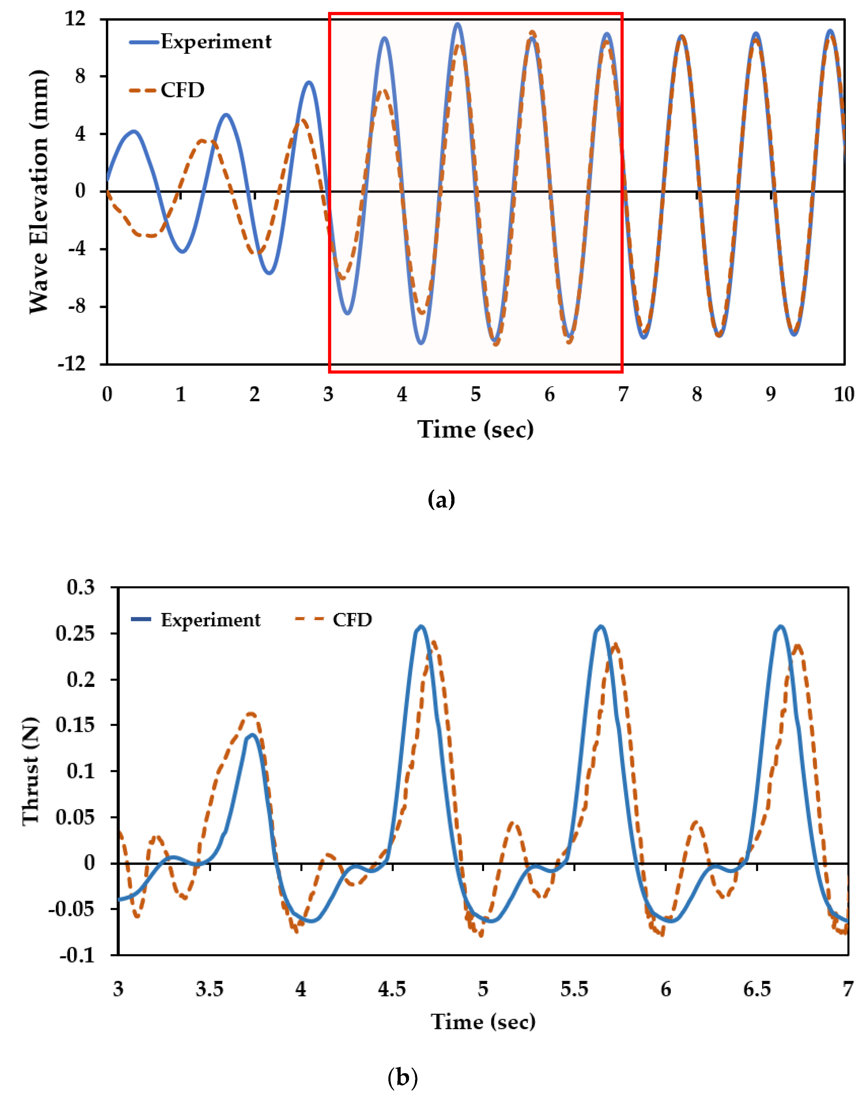
Figure 9a shows the comparison of wave profiles from 0 to 10 s.
Figure 9b shows the comparison of thrust forces for the highlighted region in
Figure 9a, from 3 to 7 s. The comparison of results validates the numerical method qualitatively.
The efficient measurement of thrust forces for the active mode of flapping foil experimentally was complicated, therefore, 2-way FSI with CFD simulation might be used to evaluate thrust and other hydrodynamic properties.
3.3. Fixed Hydrofoil
For the incident short wave displayed in
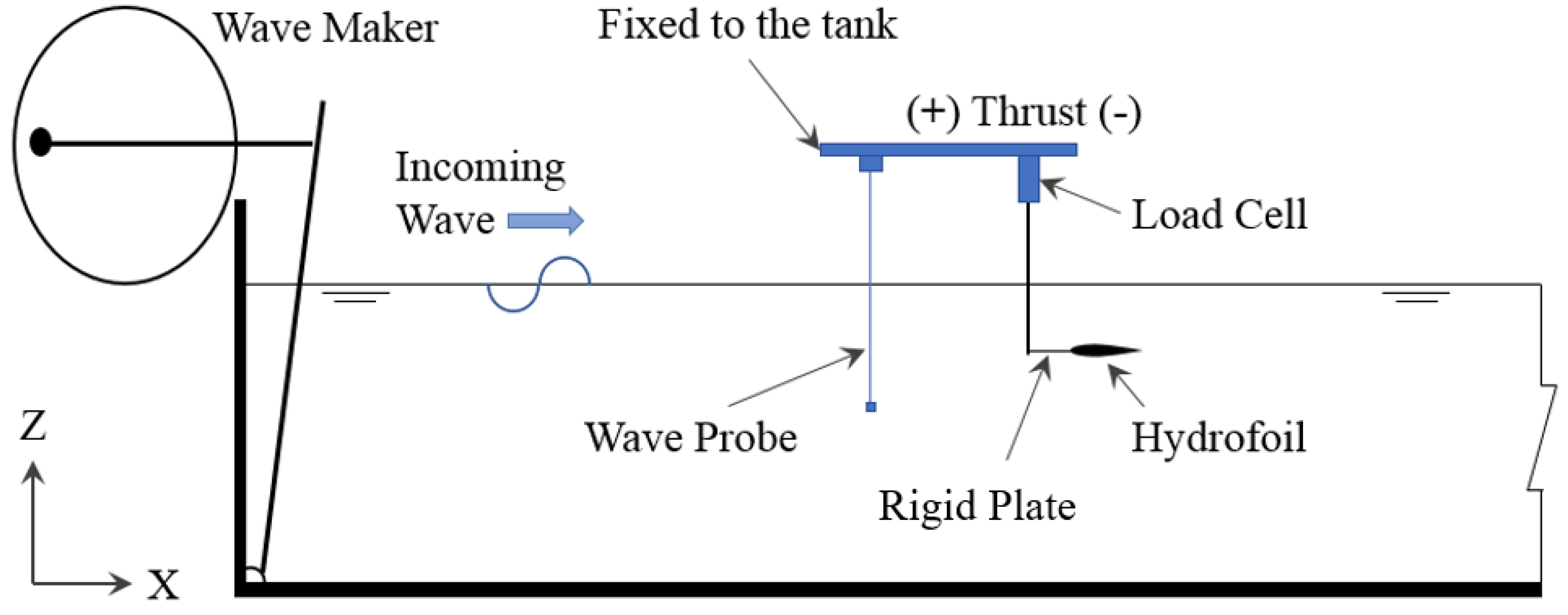
Table 2, an experiment was carried out for a fixed foil to capture the thrust forces measured in the x-direction as shown in
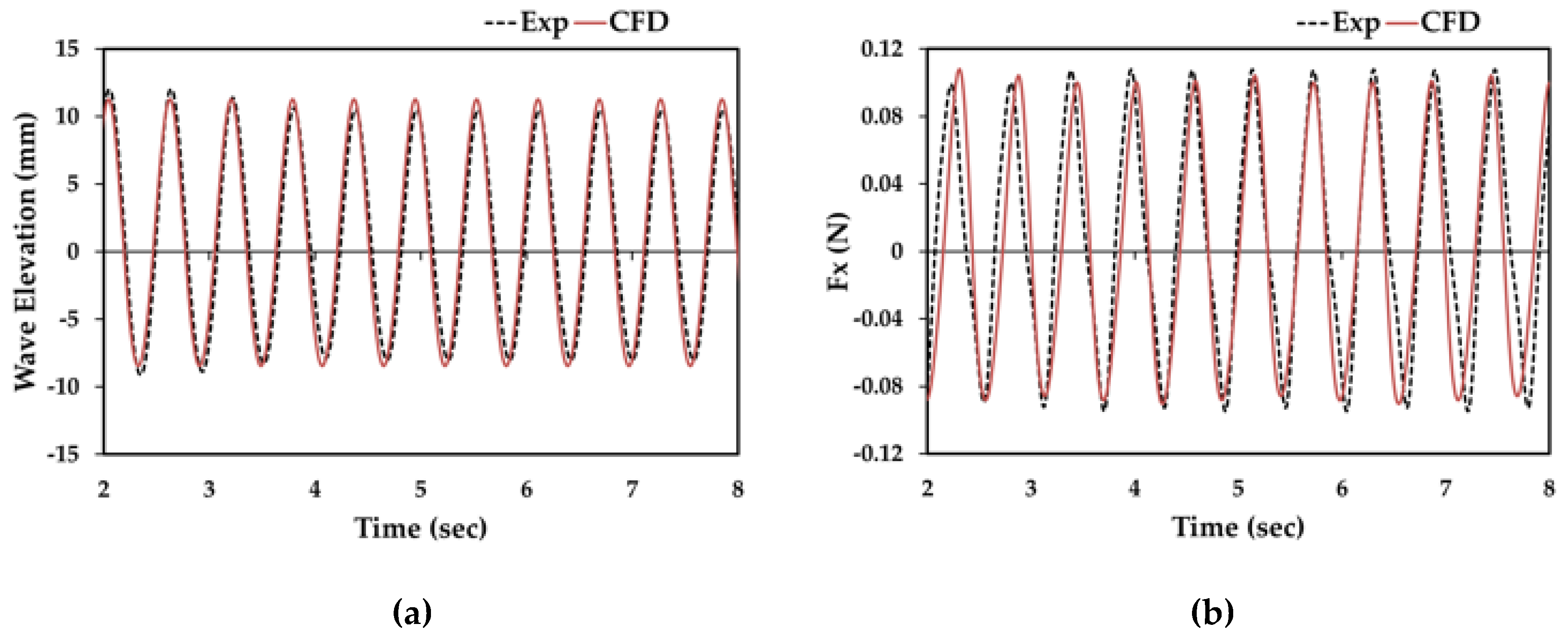
Figure 10, therefore, 1 mm thick HDPE elastic plate was replaced by a rigid stainless steel plate of same thickness and sinusoidal variation of force in the surge (Fx) was recorded and compared with the numerically evaluated results using CFD.
Figure 11a,b show the comparison of wave elevations and the pressure force variations on the fixed foil in time domain respectively. The CFD numerical results were in good agreement with experimental data.
3.4. Flapping in Still Water
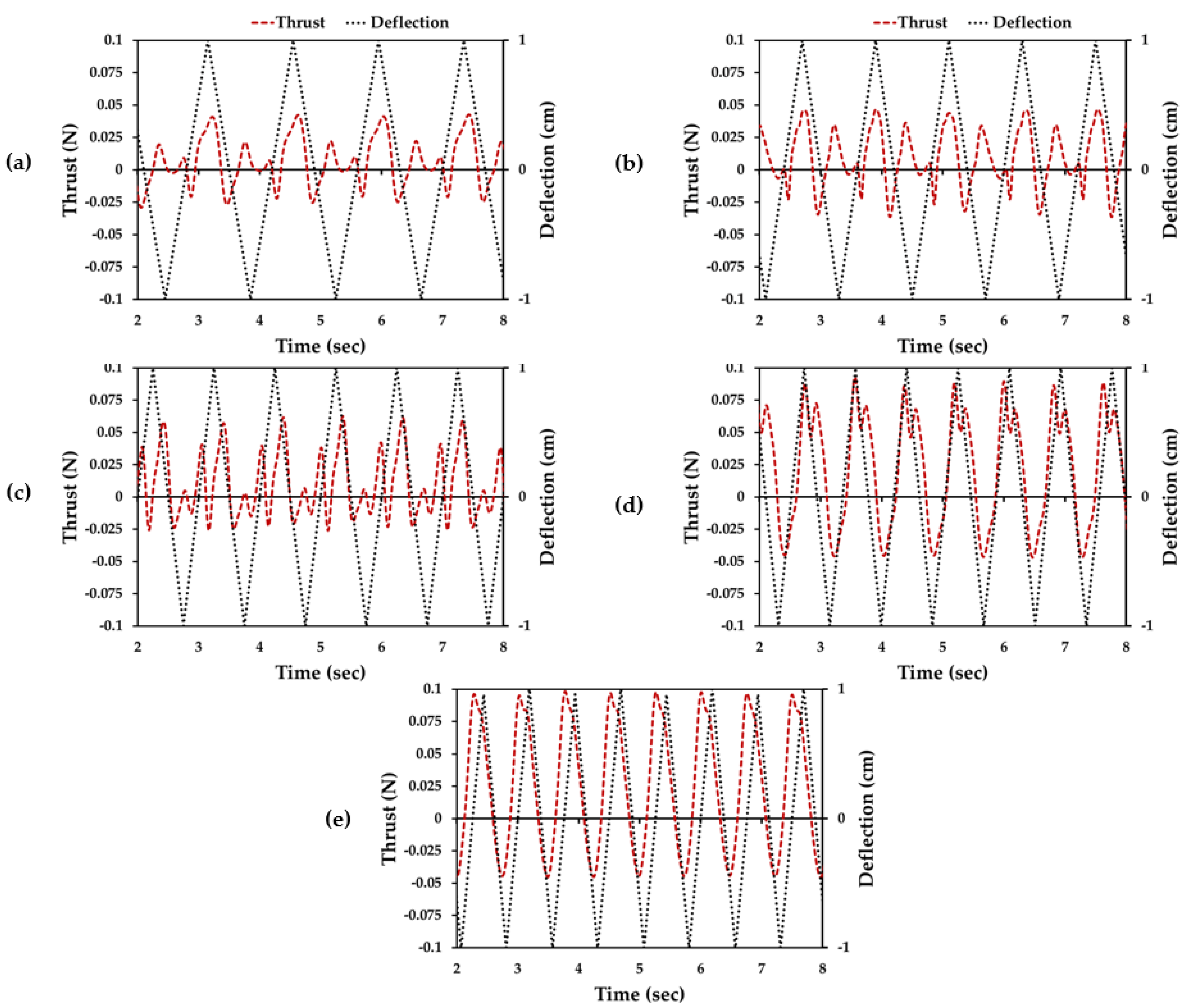
Thrust forces generated by the active flapping foil in still water with five flapping frequencies were evaluated using CFD-FSI simulation.
Figure 12a–e show the thrust plots with the trailing edge deflection of the hydrofoil for flap-1, flap-2, flap-3, flap-4 and flap-5, respectively.
Results prove that the thrust forces can be generated by the active flapping motion of the foil in still water. As the flapping frequency increased, the magnitude of thrust forces increased, however, the number of thrust peaks decreased.
3.5. Active Mode Results in Short Wave
Finally, five active modes of flapping foil were simulated in a short wave using 2-way FSI simulation and the results are displayed in
Figure 13b–f for flap-1, flap-2, flap-3, flap-4, and flap-5 respectively. Results show that the magnitude of thrust forces increased drastically in active mode with waves compared to active mode in still water and fixed hydrofoil in waves, due to its ability to convert wave energy into propulsive energy, a fixed foil could not create an effective angle of attack to efficiently transform the wave energy into propulsive energy, and in still water conditions, there was a no incoming wave or fluid flow to generate lift and thrust forces for the angle of atttacks created by the active flapping. However, 2-way FSI analysis could couple the effects of waves with active flapping; therefore, higher thrust peaks were evaluated.
Figure 13a shows the experimentally measured thrust data of passive flapping foil in a short wave specified in
Table 2. In the passive mode, there was no significant difference in the positive and negative thrust peaks, hence it was not enough to prevent the floater from drifting during the station-keeping tests [
21]. Conversely, Active modes were dominating in the positive side of the thrust plots. Therefore, active flapping foil could be a potential solution for the station-keeping problems in the short waves.
4. Conclusions
In this study, 2-way FSI with CFD simulation was used to evaluate the thrust forces generated by the active and passive flapping foils in short wave and still water conditions. Also, the numerical method was validated by making comparisons with experimentally recorded data in passive flapping foil and fixed foil modes. Simulation results confirmed the generation of thrust forces due to the flapping motion of foil in both active and passive modes. Foils were flapping at a set location and generating thrust forces against the direction of incoming waves, which was vital for the design of the station-keeping system of a floater in waves.
Results proved that the active flapping can generate thrust forces for the station-keeping of a floater in short waves. The magnitude of thrust forces can be controlled by adjusting the flapping frequency of the foil, and for further development of the flapping foil station-keeping system, CFD can be a very efficient tool to evaluate the dynamic behavior of it.
