1. Introduction
In the 21st century, the importance of exploring and developing marine resources has increasingly gained attention. With the advancement of intelligent technologies and the demand for high safety, unmanned systems are gradually replacing manned systems, becoming a trend. AUVs have become indispensable in various underwater applications. In civilian applications, AUVs are extensively utilized for subsea geological surveys, oceanographic data acquisition, offshore pipeline deployment, submersible drilling support, and maintenance of subsea infrastructure. Within military contexts, these systems serve critical roles in intelligence reconnaissance, naval mine countermeasures, submarine rescue operations, and personnel recovery missions [
1,
2,
3]. Compared to single AUV operations, the cooperative control of multiple AUVs offers significant advantages, including improved efficiency, redundancy, and the ability to handle complex tasks [
4,
5,
6].
During task execution, issues such as communication frequency, communication delay, and obstacle avoidance in complex underwater environments must be considered in the control of multiple AUVs. The paper [
7] presents a fixed-time distributed formation tracking control for multiple AUV systems, addressing issues of input saturation and uncertainties using adaptive fixed-time fuzzy logic control (FLC) methods. The proposed control strategy ensures robust and stable formation tracking under practical constraints, as validated by simulation results. The literature [
8] presents a novel approach to formation control for multiple AUVs under communication delays using a gradient descent-based delay estimator and adaptive controller. Simulation and experimental results demonstrate the method’s effectiveness in accurately estimating delays and maintaining formation stability despite variable communication delays. Event-triggered control strategies offer significant advantages by reducing the frequency of actuator activations, which in turn minimizes communication demands and energy consumption. This approach ensures that control actions are only executed when necessary, leading to more efficient system operation without compromising stability or performance. Distributed event-triggered formation control methods for multi-AUV systems have been introduced, utilizing asynchronous periodic sampling to significantly reduce communication frequency and energy consumption while maintaining stable formation performance [
9,
10,
11]. Additionally, these methods extend to multi-underwater unmanned vehicles (UUVs)recovery systems under time-delay conditions, demonstrating effectiveness in enhancing both communication efficiency and control robustness [
9,
11]. A distributed tube model predictive control (DTMPC) method has been proposed for the formation trajectory tracking of UUVs in the presence of uncertainties and external perturbations, enhancing stability and robustness in 3D formation control [
12]. This approach, combined with a finite-time extended state observer-based collision-free formation control for multiple AUVs, demonstrates robust performance under dynamic uncertainties and external disturbances [
13]. Furthermore, fixed-time dynamic event-triggered 3D formation control methods for multi-AUV systems have been presented, achieving rapid and precise formation tracking while mitigating the effects of disturbances [
14]. An Average Consensus Time-Varying Formation Control method based on an Event Triggering Decoupling Mechanism (ETDM-ACTVF) for underactuated AUVs has also been introduced, enhancing formation stability and control precision while reducing communication and energy demands, as demonstrated through comprehensive numerical simulations [
15].
In the complex underwater environment, AUVs must consider the challenges of avoiding collisions with each other and with obstacles during coordinated movements. A real-time collision avoidance framework is essential for the safe control of AUVs. The Artificial Potential Field (APF) method has been applied in the field of real-time collision avoidance for over thirty years, first appearing in Khatib’s pioneering paper [
16].
A Distributed Lyapunov-Based Model Predictive Control method based on APF and an Extended State Observer (ESO) has been proposed to effectively address formation tracking and collision avoidance for multiple AUVs under ocean disturbances [
17]. Improved APF algorithms combined with affine transformation and Software-Defined Networking (SDN) technology have been introduced for effective obstacle avoidance and path planning in multi-AUV systems facing ocean current disturbances [
18,
19]. An adaptive dual-channel event-triggered fuzzy control scheme utilizing SDN technology and an improved APF algorithm has been presented for effective obstacle avoidance and path planning in multi-AUV systems amidst ocean disturbances [
20]. Additionally, a finite-time position and attitude tracking control method that combines artificial potential field and virtual structure techniques ensures effective formation control and collision avoidance for multiple AUVs over varying seabed terrains [
21].
CBFs have been recently introduced as an optimization-based controller that provides safety guarantees for nonlinear systems. Due to their robustness and practical performance, CBFs have found a wide range of applications across various fields, including robotics, multi-agent systems, quadrotor aircraft, ASVs, and AUVs [
22,
23,
24,
25,
26,
27]. Compared to APFs, CBFs offer stronger robustness against model uncertainties and noise disturbances, and they can avoid the issue of local minima that can prevent the system from reaching its target [
28]. A novel approach using CBFs for collision avoidance and liveness in multi-agent systems has been introduced, comparing centralized and decentralized policies. The study focuses on the Predictor–Corrector for Collision Avoidance (PCCA) algorithm and finds that decentralized policies often result in gridlocks due to stable equilibria. In contrast, centralized and PCCA policies avoid gridlocks with unstable equilibria, ensuring efficient navigation and collision avoidance [
23]. Fu et al. propose a safe consensus tracking method with guaranteed full state and input constraints using a CBF-based approach, ensuring state and input constraint satisfaction in multi-agent systems [
24]. Additionally, Wen et al. present a distributed MPC-based robust collision avoidance framework for multi-agent systems, enhancing collision avoidance and system robustness [
25]. A decentralized robust collision-avoidance framework for cooperative multi-robot systems using Gaussian Process-Based (GP)-CBFs has been proposed. This framework addresses model uncertainties by estimating them with Gaussian processes and incorporating these estimates into the design of robust CBFs, thereby reducing computational complexity and conservativeness in collision-avoidance behaviors. The approach integrates Control Lyapunov Functions with CBFs to ensure both safety and performance. Simulation results demonstrate the effectiveness and stability of the method in multi-robot coordination tasks, particularly in handling collision-avoidance and maintaining system liveness [
26,
27]. A safety-critical cooperative target enclosing control method for underactuated Autonomous Surface Vehicles (ASVs) has been introduced, leveraging input-to-state safe high-order control barrier functions to ensure collision avoidance among ASVs and obstacles while guaranteeing input-to-state stability and safety. The framework includes a finite-time fuzzy predictor for learning unknown dynamics and a distributed target estimator for position recovery, ensuring effective target enclosing and obstacle avoidance [
22].
Building upon the preceding discussion, this study focuses on obstacle avoidance consensus control for multi-AUV systems operating in underwater environments characterized by communication delays and intermittent connectivity. To address these challenges, an event-triggered consensus control framework utilizing CBFs is proposed for leader-following multi-AUV configurations. This research aims to advance cooperative control methodologies for AUVs, thereby facilitating the broader adoption of AUV technology in marine exploration and operations. The principal contributions of this study are outlined as follows:
Unlike traditional intermittent time-triggered approaches [
29,
30], this work uses a novel time-delay piecewise differential inequality incorporating an exponential decay term. This framework systematically unifies state delays, intermittent control policies, and event-triggered mechanisms, enabling robust stability analysis under non-ideal communication conditions.
The proposed controller replaces the request-response mechanism in reference [
31] with a broadcast mechanism, reducing the need for continuous communication between AUVs and optimizing communication efficiency.
A nominal-optimized control scheme is developed to solve the obstacle avoidance problem for multiple AUVs. A CBF is used, and obstacle avoidance safety conditions between unmanned vehicles and obstacles are derived. Based on the safety conditions and input constraints, a QP problem is formulated to optimize the control signals in real-time, ensuring the safe control of the multi-AUV system.
The remainder of this paper is organized as follows:
Section 2 formalizes the problem statement and foundational preliminaries. The main results are presented in
Section 3.
Section 4 validates the nominal controller and CBF-based strategy through comprehensive simulations.
Section 5 presents the concluding remarks and future research directions.
2. Preliminaries and Problem Formulation
2.1. Graph Theory
Suppose there are AUVs and a virtual leader as the research subjects. Define as the communication topology graph of the multi-AUV system. The set of nodes in the multi-AUV system is denoted as . represents the set of edges. The neighbor set of AUV is defined as . denotes the adjacency matrix of the underwater vehicle network communication. If the th AUV can receive information from the th AUV, then the element , otherwise, . Specifically, represents the pinning matrix of the root node , defined similarly to .
Definition 1. For the communication topology graph , the Laplacian matrix of the communication topology is typically defined as
where is the in-degree matrix, and . For convenience, let , where is the pinning matrix. Definition 2. A spanning tree of the communication topology graph is a directed tree in which every vertex except one has exactly one parent. The unique vertex without a parent is referred to as the root, and there exists a directed path from the root to every other vertex in the graph.
2.2. Control Barrier Function
The system dynamics are assumed to follow a control-affine structure, expressed as follows:
where
denotes the state vector,
represents the constrained control input, and
and
are locally Lipschitz continuous vector fields. Let
denote the safe set, which defines the region where the system states should remain. The goal is to synthesize a control law that ensures the forward invariance of the set
, that is, if
, then
. To enforce this, the safe set
is defined as the superlevel set of a zeroing Control Barrier Function (CBF) candidate
:
Taking the time derivative of
along system trajectories yields
where
and
are the Lie derivatives of
along
and
, respectively.
To ensure safety, the admissible control space
is defined as
Lemma 1 [
32]
. Given a set defined by (4)
and a ZCBF defined on , with , any Lipschitz continuous controller such that for the system (2)
renders the set forward invariant, and is asymptotically stable within . Furthermore, by selecting the scalar function where , the control input needs to satisfy the following inequality: which ensures the forward invariance of .
2.3. Feedback Linearization of AUV Model
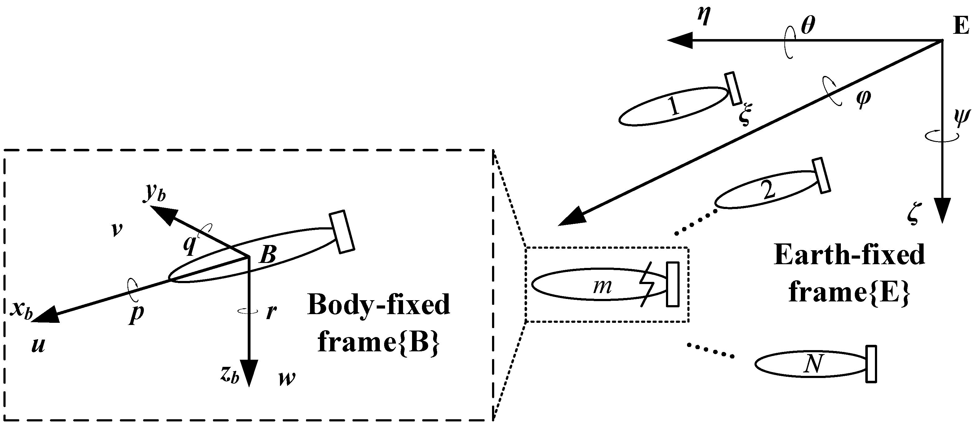
The kinematic and dynamic models of the AUV are described in two coordinate systems, as shown in
Figure 1. These include the Earth-fixed coordinate frame
, which defines the global position and orientation of the AUV in inertial space, and the body-fixed coordinate frame
, which characterizes the vehicle’s local motion and force interactions relative to its principal axes.
Table 1 summarizes the names and symbols of the state variables in each coordinate axis.
This article focuses on a torpedo-shaped AUV, where the negligible influence of roll dynamics on translational dynamics justifies the omission of rolling velocity in the model. The kinematics and dynamics models of the AUV are described as follows:
where
represents the position state information of the AUV,
represents the velocity state information of the AUV. The Jacobian matrix, denoted as
, represents the transformation matrix from the body-fixed coordinate system to the Earth-fixed coordinate system.
, and the inertia matrix and additional inertia matrix are expressed as
and
.
, presenting the situation of the Coriolis matrix.
denotes the hydrodynamic viscous matrix. Their specific representations are as follows:
is a vector, which is generalized buoyancy and gravitational forces:
where
represents the vertical coordinate of the center of buoyancy;
.
is the AUV’s controller input. The parameters of the AUV model are provided in [
33].
To facilitate subsequent linearization calculations, (7) is rewritten in the following form:
where
.
Let
. After defining an output function
, the dynamics model can be represented as a general nonlinear system as follows:
where
,
.
According to the definition of the Lie derivative, the expression for
are computed as
where
Similarly, the expressions for
and
can be obtained. Due to space limitations, they are not presented here but can be referenced in [
10].
The coordinate transformation is adopted:
In this transformed coordinate frame, the control input
is analytically formulated as
where
,
.
It follows that
where
.
The above feedback linearization process is applied to a single AUV. Since all AUVs in this study share identical hydrodynamic and kinematic properties, the same linearization procedure can be extended to the rest of the agents. Accordingly, the feedback-linearized dynamic model for each AUV can be reformulated into a decoupled state-space form as follows:
Here, and are generalized position and velocity vectors are obtained from the extension of the single-AUV linearized coordinates and to the th AUV. It should be noted that is a vector-valued state and should not be confused with the scalar variable used earlier to denote the -directional position component. While contains the x-coordinate as one of its elements, it encapsulates all relevant spatial dimensions of the AUV’s motion.
Detailed derivations and parameter specifications of the AUV model are comprehensively addressed in prior studies [
10,
34]. Nevertheless, feedback linearization requires nonlinear coordinate transformations and Lie derivative computations, which may pose challenges for real-time implementation on embedded AUV platforms. This work focuses on theoretical controller design under the assumption of sufficient onboard computational resources. With the continuous improvement of embedded processors in modern AUVs, such model-based control strategies are considered feasible. Future work will address real-time constraints by exploring computationally efficient alternatives.
2.4. Problem Formulation
This article considers a multi-AUV system composed of
autonomous underwater AUVs. In this article, we will discuss a kind of multi-AUV system, including
AUVs. The dynamics of the
th AUV are described as (23):
For the sake of writing simplicity is used instead of , is used instead of and is used instead of , where represents the position state of the th AUV after feedback linearization, represents the velocity state, represents the differentiable nonlinear terms, where represents the inner state delay and . represents the output of the AUV actuators (or controller input), . The velocity constraint is . The control input constraint is , , and and are known normal numbers.
The dynamic model of the leader is described as follows:
where
is the position vector,
is the velocity vector,
,
,
is a continuous constant,
.
Definition 3. For the multi-AUV system, if for any follower the following conditions are satisfied: , , , then the leader-following consensus is achieved.
Remark 1. The local information of each AUV includes its own velocity (which can be obtained through onboard sensors such as IMU), as well as relative state information of nearby AUVs obtained through digital communication or onboard sensing. In this study, an ideal broadcast communication model is assumed, meaning that the required neighbor information is exchanged reliably and instantaneously. This simplification allows the focus to remain on the evaluation of the control strategy itself without additional complexity from the communication model.
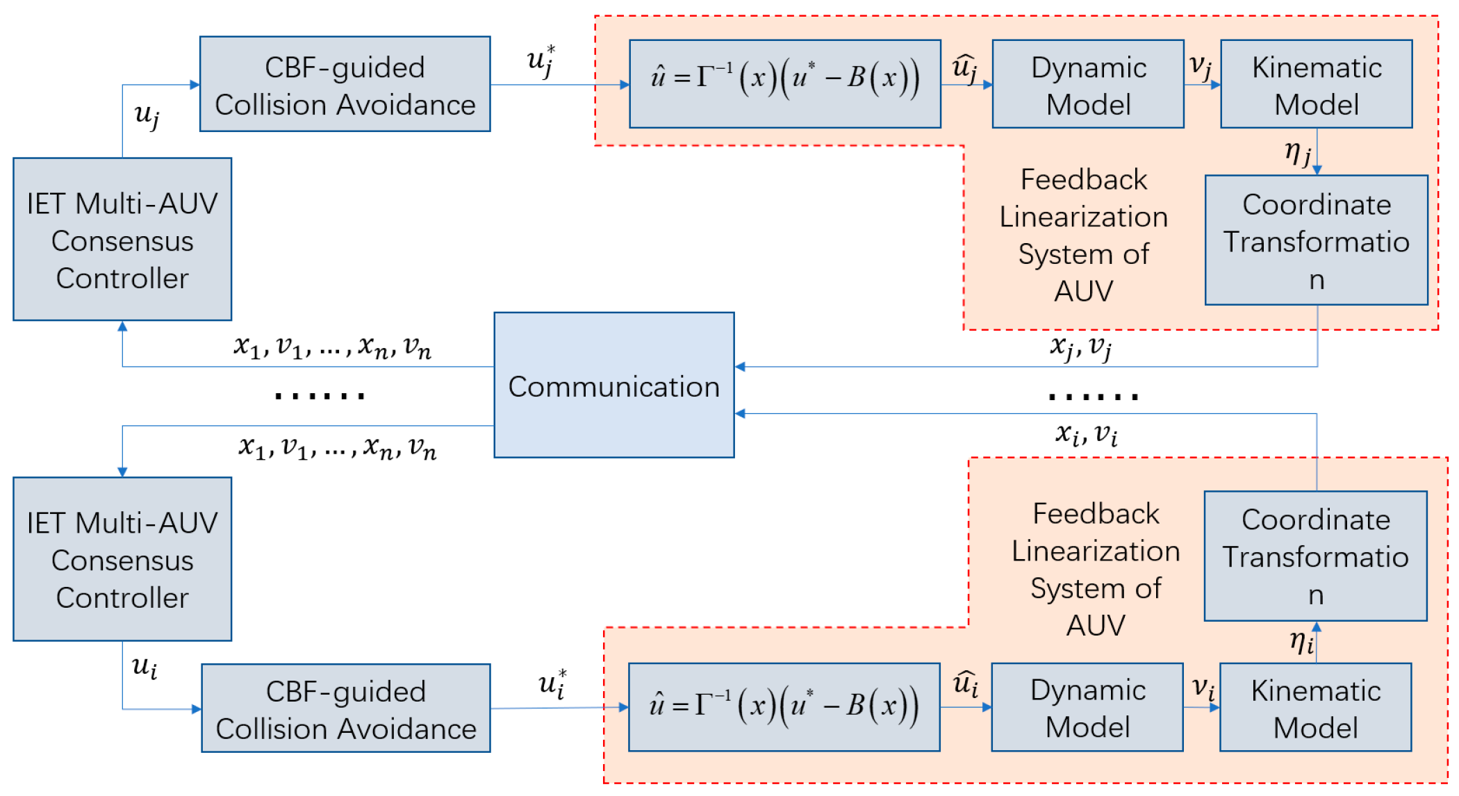
Figure 2 illustrates the proposed control architecture, which integrates intermittent event-triggered consensus with safety-critical obstacle avoidance. The framework combines (1) broadcast-based intermittent communication for state updates, (2) time-delayed piecewise differential inequalities for leader-following coordination under intermittent connectivity, and (3) real-time QP optimization with zeroing CBFs for obstacle avoidance, by unifying feedback-linearized AUV dynamics with event-triggered mechanisms.
3. Main Results
In this section, a discontinuous event-triggered consensus control method based on barrier functions is proposed for the control of System (23). The design of the controller consists of two main steps. First, a nominal discontinuous event-triggered consensus controller is proposed without considering obstacle avoidance requirements. Next, the obstacle avoidance requirement is formulated as the forward invariance of a safe set, which is then enforced through a barrier-function-based constraint. Subsequently, the controller’s input range is constrained using CBF. A QP framework incorporating barrier function constraints is constructed to refine the nominal controller with minimal deviation, ensuring obstacle-free navigation for the AUV system under safety-critical conditions.
3.1. Nominal Leader-Following IET Consensus Controller
In multi-AUV systems, the design of effective control protocols is crucial for ensuring the desired system behavior. A strategy involves periodic intermittent control, which strategically divides the control interval to enhance system efficiency and reduce computational load. This paper investigates the use of such control mechanisms under specific conditions, extends existing methods by integrating an event-triggered approach to optimize system performance further.
Consider the interval , partitioned into consecutive subintervals where and denotes the length of each subinterval. Within each subinterval, the active control period is defined as , with representing the duration of control activity.
Define the state errors as
. The dynamics of the state error system under intermittent control can be expressed as:
where
is a time-dependent function defined as:
and
.
For the th AUV within , an event-triggered sequence is established, starting with and satisfying .
The control input for follower
is given by:
where
represents the control gain,
The event-triggering condition is described by the function:
where the measurement errors
and
are given as:
and
, and
, and .
Remark 2. The proposed control protocol utilizes a broadcast communication mechanism, in contrast to the request-response strategy observed in prior research [
31].
This approach significantly reduces the need for continuous communication between agents, enhancing overall system efficiency [
35]
. In the context of controller (27),
and should be used instead of and . This adjustment is necessary for two reasons. First, as indicated in [
32,
36]
, the event-triggered mechanism is only applied to the control protocol of followers. Communication between followers and the leader is typically unidirectional, with the leader solely sending signals, which means the leader does not receive the followers’ trigger instants. Second, using and as in [
37,
38]
leads to the relationship , which inevitably introduces measurement errors and .
Lemma 2. Consider the function under the conditions:
Assuming that and certain constraints ( ) on . Then it follows that: , which implies asymptotic stability of the system. Proof. The proof process requires three distinct steps.
Step 1: First, define as follows:
For any
, if
, then we have
Define
, let
And
. For any
, we have
Consider
. On one hand, if there exists
such that
, then
is a maximum point of
for
. Therefore,
On the other hand, for any
, if
we claim that
. From (33) and
, we get
Considering the analysis of the two aspects mentioned above, we have:
This implies that
is nonincreasing over the interval
. Consequently, we have
, i.e.,
If
, we derive from (30) and (37) that
where
. If
, we obtain
Step 2: Let
If
for
, then we have
where
. Following a similar proof process as in steps (35)–(38) in step 1, we obtain:
Step 3: This step requires consideration of two distinct cases.
Case 1 . Based on steps 1 and 2, for , we obtain
Consequently,
where
and
. When
,
thus
When
thus
When
where
Applying L’Hospital’s rule, we get:
From (50) and (51), it follows that:
Thus, from (49) and (52), we conclude:
.
Case 2 . From steps 1 and 2, for
thus
Similar to the approach in Case 1, during
So we also have
. □
Remark 3. Drawing inspiration from [
39,
40]
, the event-triggered function (28)
incorporates a decayed exponential term , which allows for more flexible control of the convergence rate through parameter adjustment. However, this term also introduces significant challenges in theoretical analysis. The novel time-delay piecewise differential inequality (29)
is proposed to address these difficulties, which effectively combines state delay, intermittent control, and event-triggered strategies. When the exponential term is removed, (29)
simplifies to the form found in [
30,
41,
42]
, specifically: When the state delay is eliminated, (56)
simplifies to the form found in [
39]
, specifically: 3.2. Consensus Analysis
Let
, and
. Thus, the global state error system under the IET protocol is described as follows:
where
the matrices
,
,and
are defined as:
; where , and denotes the Kronecker product.
Theorem 1. Considering the system (25) with the IET protocol, leader-following consensus can be achieved if Assumptions 1 and 2, along with conditions (1) and (2), are met.
(1): with .
(2): with and satisfying and , respectively.
Additionally, the Zeno behavior is excluded.
Proof. When the control strategy (27) is applied to system (25), the first step ensures that the leader-following consensus in speed and position is achieved, while the second step confirms that Zeno behavior is eliminated in the multi-AUV system.
Step 1: Under the condition for , it follows that
By utilizing Young’s inequality, we obtain the following expression from (59):
where constant
. Inserting (60) into (59) results in
where
, and
). The Lyapunov function is chosen as:
where
. Define
.
Case 1. For , the velocity estimation is given by
From (62), we derive the inequality:
where constant
.
By applying the system dynamics and combining the bounds from Assumption 2, we obtain
where
and
are positive constants.
By substituting (65) and (64) into (63), we obtain
where
with
and
. By condition (1
, we can gain
. Then we have:
where
and
.
Case 2. For ), the time derivative of is given by:
where
. Based on Lemma 2 and condition (2), we conclude that
, implying that the system described by Equation (13) is capable of reaching leader-following consensus.
Step 2: Define . Since the leader’s nonlinearity , representing acceleration, is tracked by all followers; it is reasonable to assume it is bounded, i.e., . For , we have
From Step 1, we know that
, which implies that
,
, and
are all bounded. Therefore, we get:
where
,
with
. Given that
, it follows that
Let
. From (28) and (71), when
, we have:
Thus, we get
. This ensures that Zeno behavior is precluded. □
Remark 4. The addition of the decayed exponential term in function (28)
effectively reduces the frequency of event triggers. This approach is similar to that in Remark 3 of [
39]
, balancing system performance with reduced computational or communication overhead. Remark 5. Zeno behavior refers to a scenario in which the controller is triggered infinitely often within a finite time interval. To exclude zeno behavior, it must be shown that for any AUV where . Preventing zeno behavior reduces the frequency of controller updates, significantly lowering computational and communication costs.
3.3. CBF-Guided Obstacle Avoidance
If the nominal controller designed in the previous section is applied directly, obstacle avoidance cannot be guaranteed. To address this, we employ a CBF-based method that minimally modifies the nominal controller only when collision risks arise. The key idea is to encode obstacle avoidance as the forward invariance of safety sets, and restrict admissible control inputs via CBFs.
Assume that . We denote as the nominal controller. Given the communication topology, we establish obstacle avoidance constraints based on barrier functions. The CBFs in this section only constrain the position and velocity states in the , , and directions. Therefore, only is modified. In the modified trajectory of the leader, the heading angle and pitch angle are calculated according to the formulas.
Considering the case where the nonlinear disturbance terms are zero, we first represent the system in the following form to apply Theorem 1
- A.
Control Barrier Functions Based on Obstacle Avoidance Conditions
We denote the nominal controller as . Given a communication topology, we establish obstacle avoidance constraints based on barrier functions.
We address the obstacle avoidance problem between AUVs and static obstacles using the following approach. Suppose the safety radius of all AUVs is , and the radius of obstacle is . The parameter is determined based on the size of the AUVs or can be artificially set to allow for safe operation. Since we model both static and dynamic obstacles as circular, static obstacles can be considered a special case of dynamic obstacles with zero velocity and acceleration. Therefore, for all obstacles, we assume the velocity and acceleration are bounded by and , respectively. Additionally, we assume that the acceleration of the detected dynamic obstacle is known, which can be obtained using a robust differentiator.
For a follower and a obstacle
, let
,
. The condition to avoid obstacle collisions requires
, where
, meaning the AUV should always maintain a safe distance from the obstacle. Following the derivation in a similar manner to that in [
24], we can encode the obstacle avoidance condition as the forward invariance of certain sets. The obstacle avoidance set for the
th AUV can be expressed as:
where
The forward invariance of such sets ensures that each AUV remains at a safe distance from all obstacles throughout its motion, thereby achieving obstacle avoidance.
It can be seen that
is the level set of
, which will act as a ZCBF candidate. The forward invariance of
can be ensured by satisfying the ZCBF constraint in (6). Combining (6) and (75), we obtain the following safety barrier constraint:
Let the right side of the above equation be denoted as
, then the safety barrier constraint for the
th AUV is given by
which is a linear constraint on
. Furthermore, following a similar argument in [
43], it can be shown that each AUV
only needs to consider collision avoidance for AUVs and obstacles within the distance
, since the ZCBF constraint (3) is automatically satisfied for objects outside this set. This defines the dynamic obstacle avoidance neighborhood
. For safety, it is required that
so that the required relative position and velocity information can be obtained. This is what we need to do in the subsequent study.
- B.
Minimally Invasive Obstacle Avoidance Using a QP-Based Controller
To ensure that the primary control objective is preserved, the obstacle avoidance strategy should be minimally invasive, modifying the nominal controller only when necessary. Since the safety constraints derived earlier are linear in the control input, a quadratic cost function is introduced to penalize deviations from the nominal control command in the least-squares sense, resulting in the following QP problem:
When the system is safe, the QP-based controller coincides with the nominal controller. Only when a collision risk is detected does it deviate to ensure safety, while still respecting input and speed constraints. This approach thus achieves a minimally invasive safety modification of the nominal controller .
4. Simulation Results
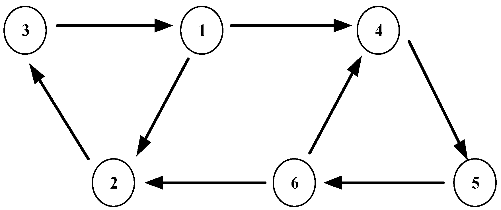
This section first presents the control performance of the nominal controller, and subsequently demonstrates the effectiveness of the designed CBF-based obstacle avoidance controller. The communication topology of
AUVs is illustrated in
Figure 3. Initial states of individual AUVs are listed in
Table 2, while numerical values of simulation parameters are provided in
Table 1. In the obstacle avoidance controller, control intervals will be eliminated near obstacles due to the urgent requirement for rapid actuator parameter adjustments to steer AUVs away from hazardous zones. The desired trajectory is given by the following equations:
The control parameters and partial initial values are given in
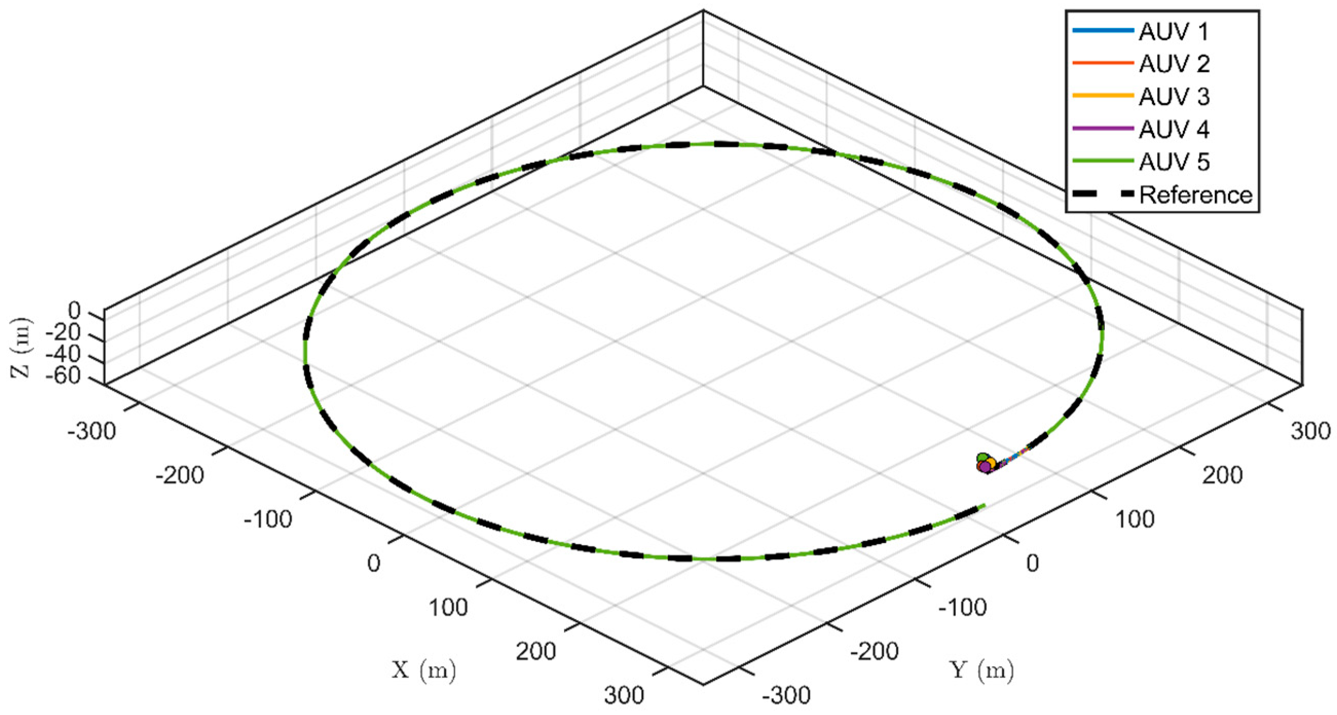
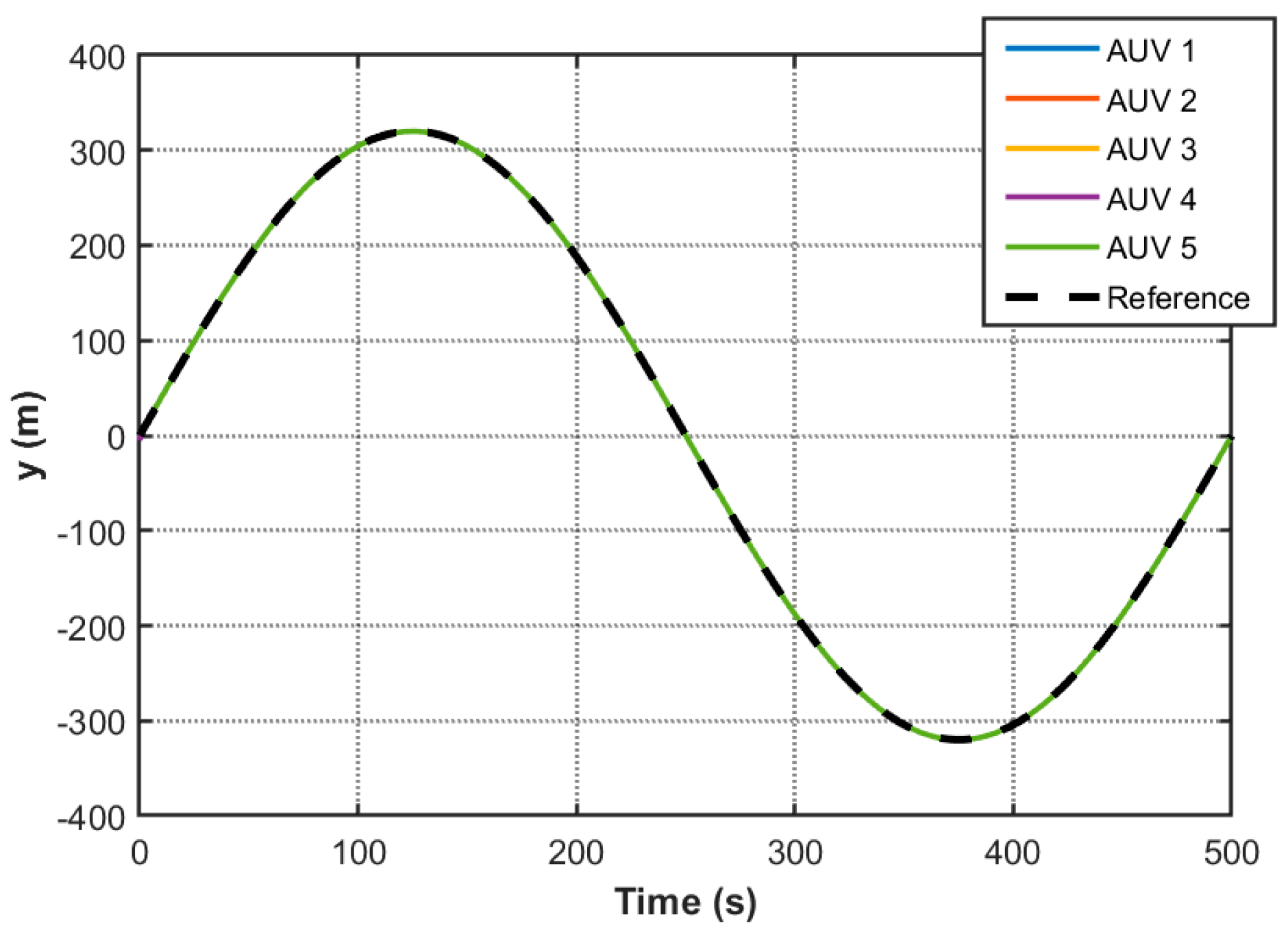
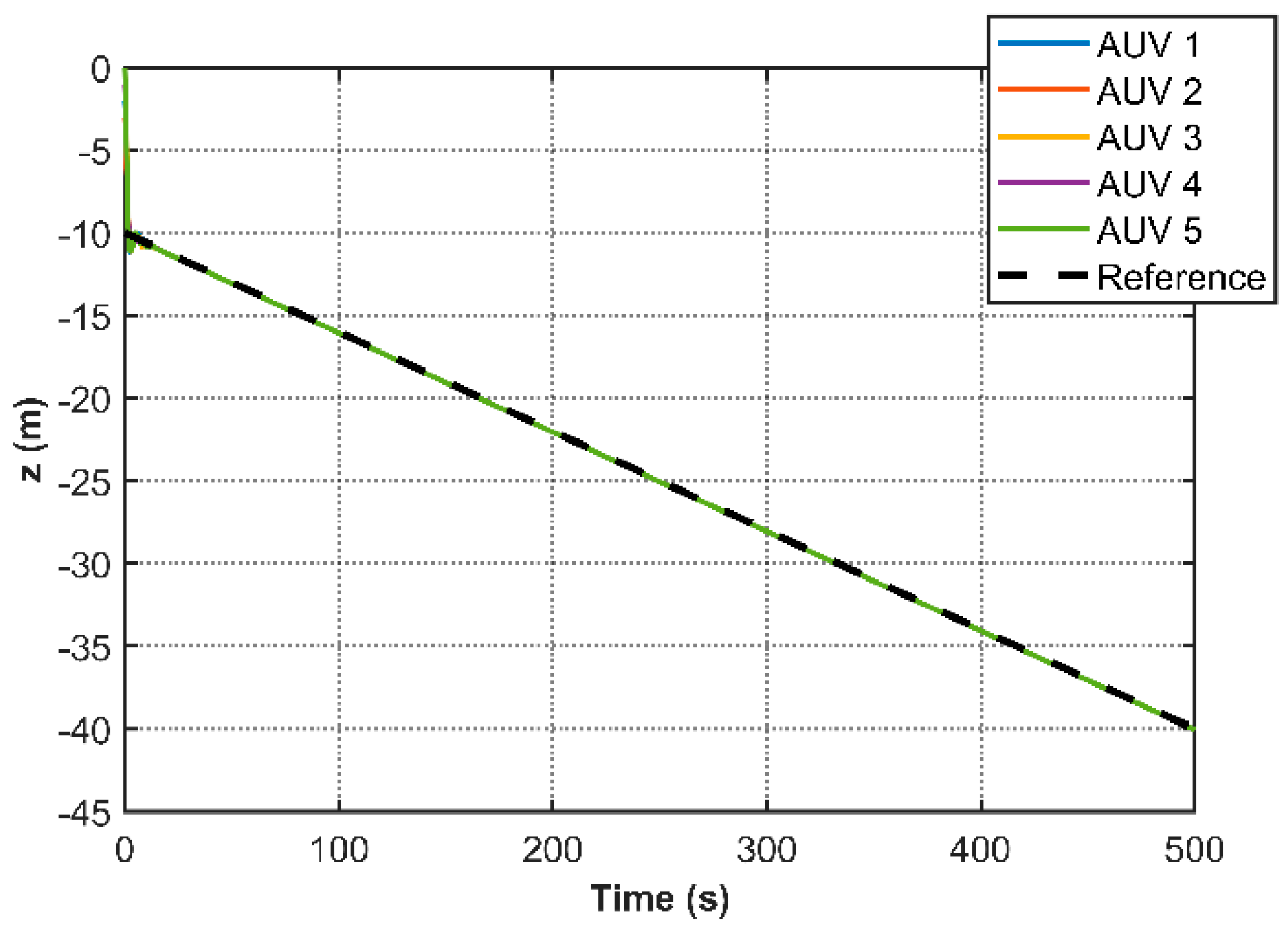
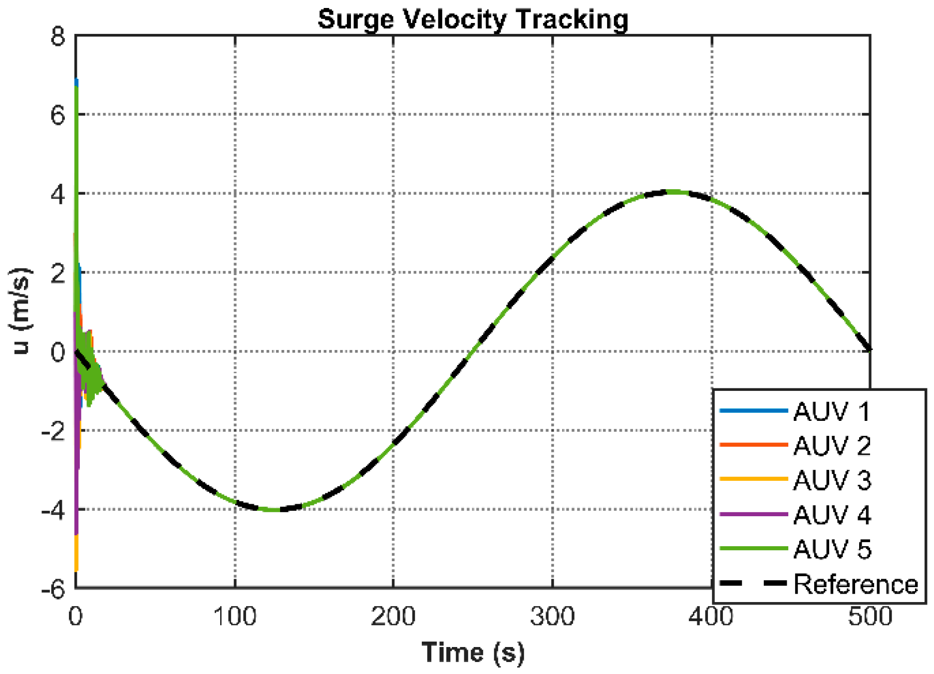
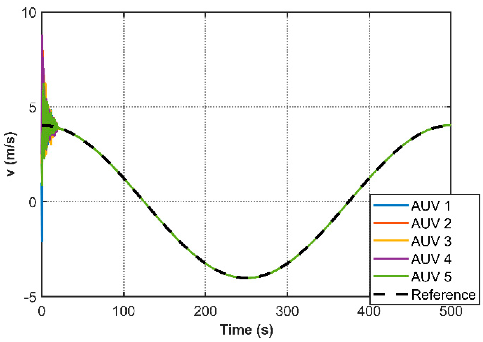
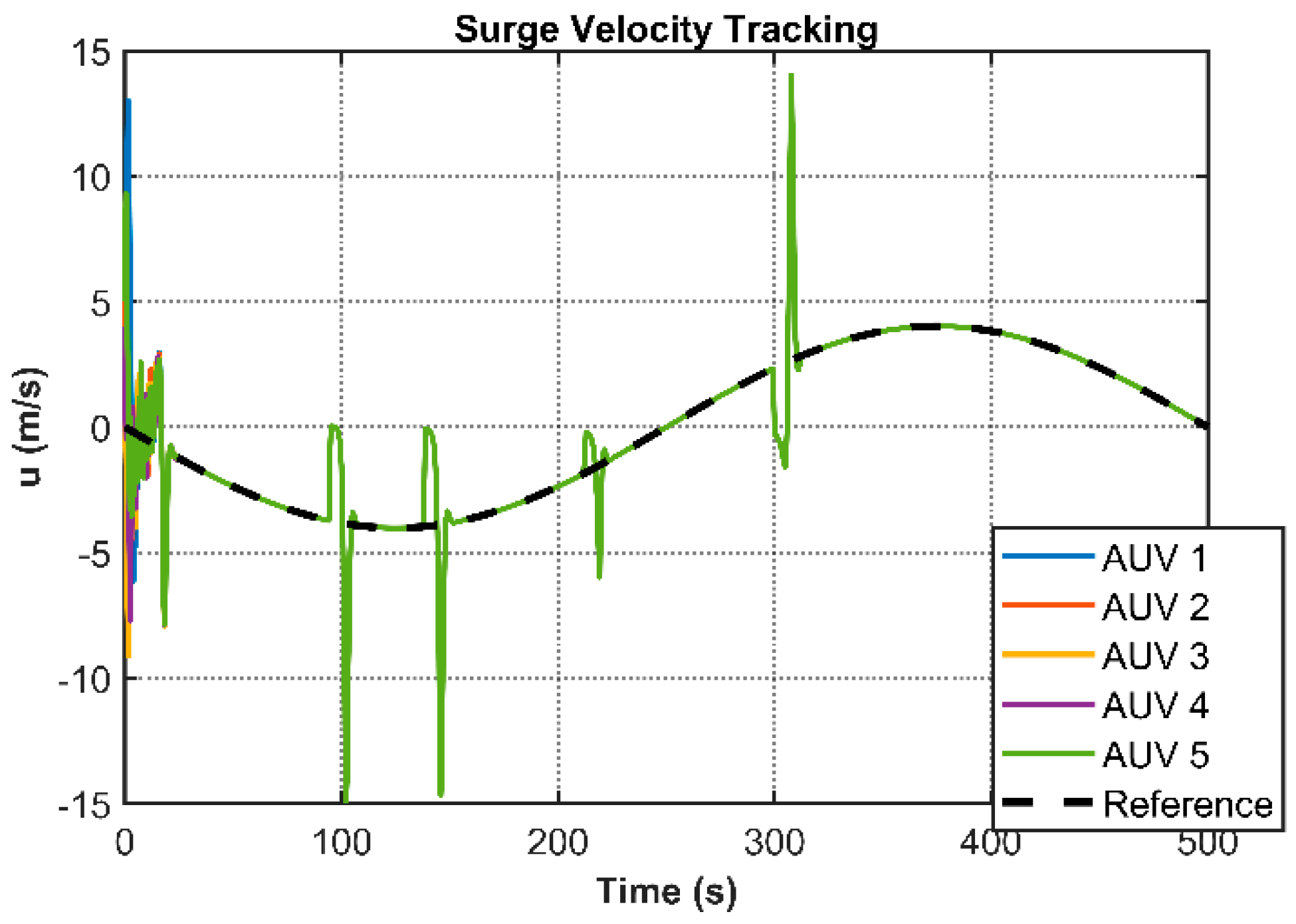
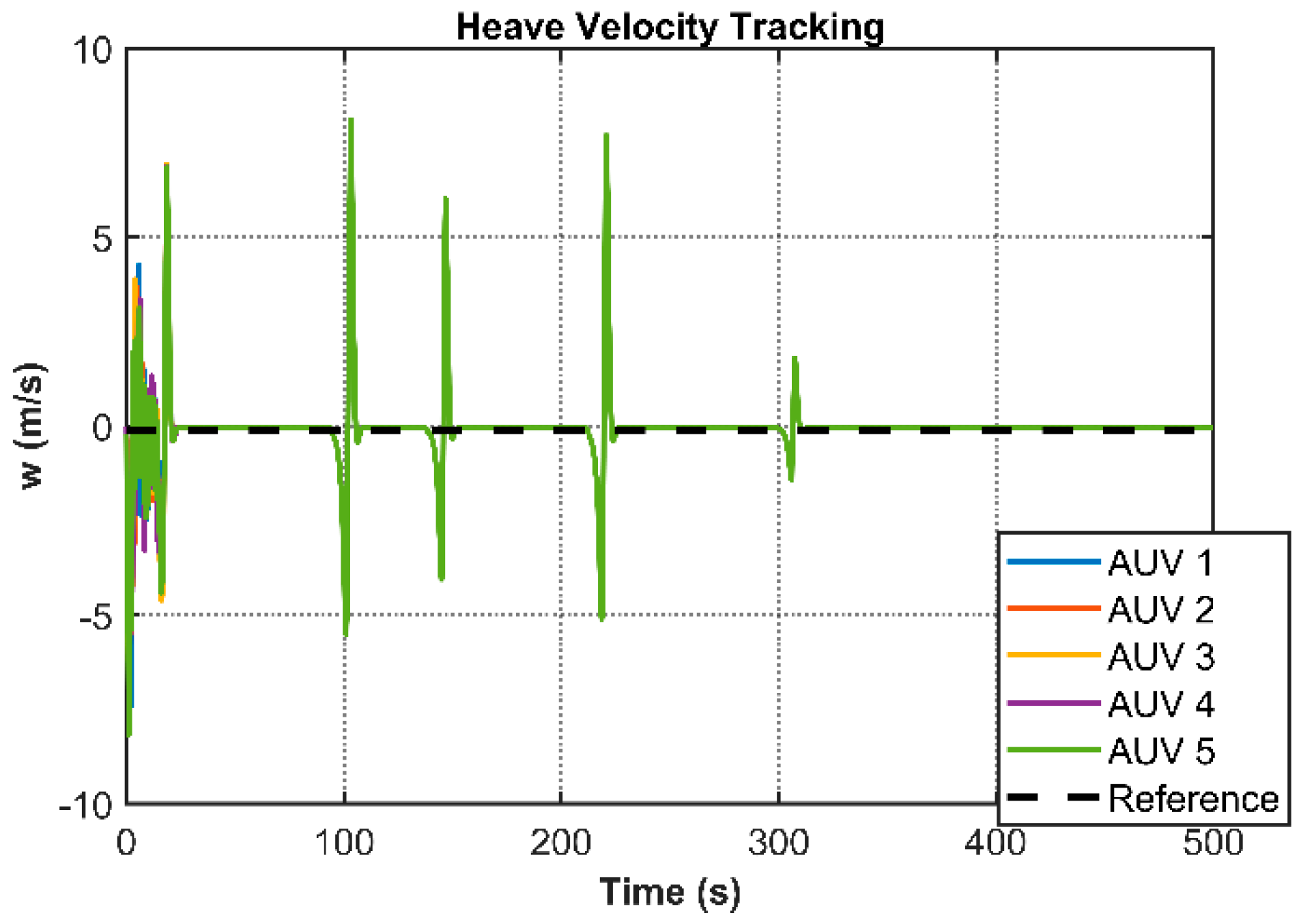
Table 3. The simulation results comprehensively validate the performance characteristics of the proposed control framework. Under the nominal controller configuration,
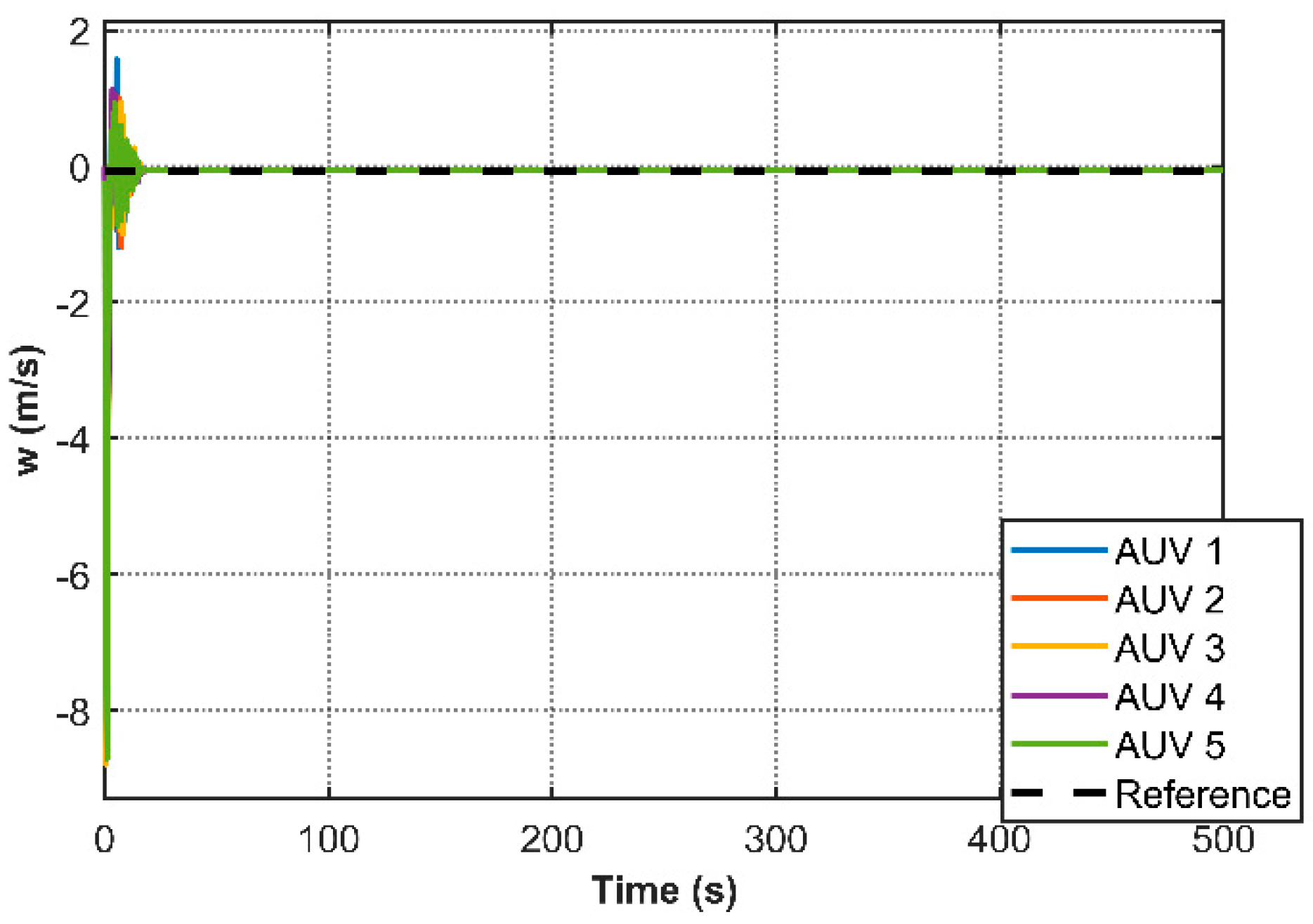
Figure 4 illustrates the stabilized 3D cooperative motion trajectories of multiple AUVs, while
Figure 5,
Figure 6,
Figure 7,
Figure 8,
Figure 9 and
Figure 10 present the transient responses of individual state variables. These plots demonstrate asymptotic convergence of all states to a common equilibrium, confirming consensus achievement across the AUV network. Notably,
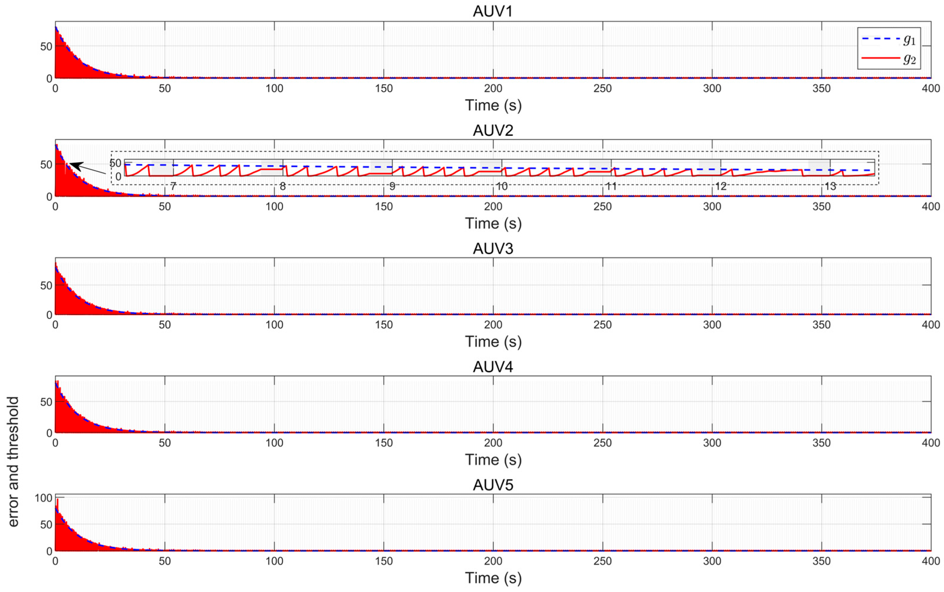
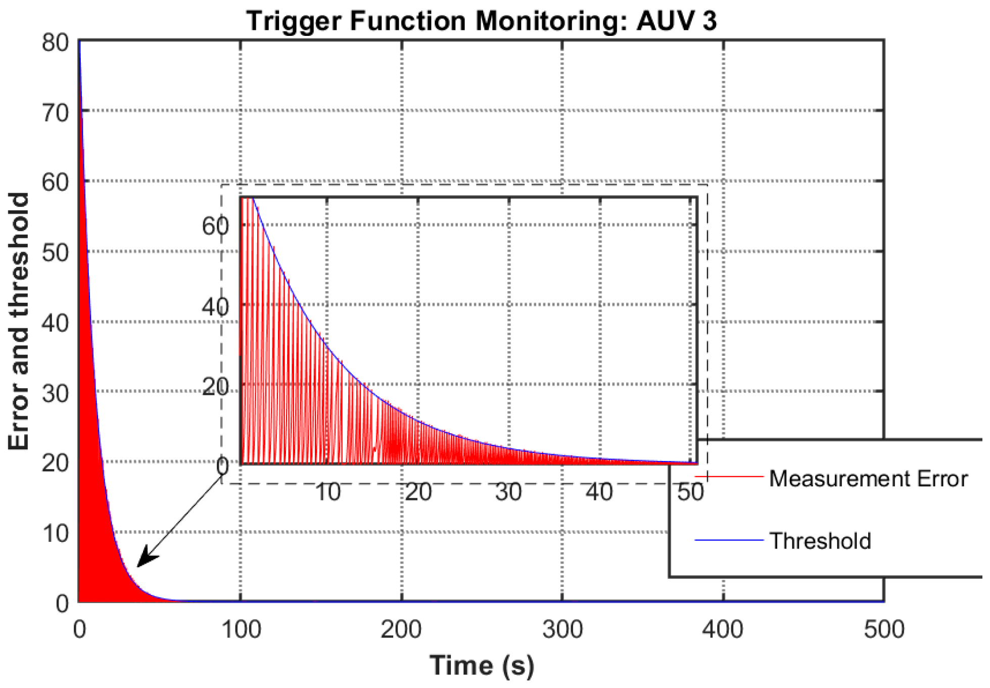
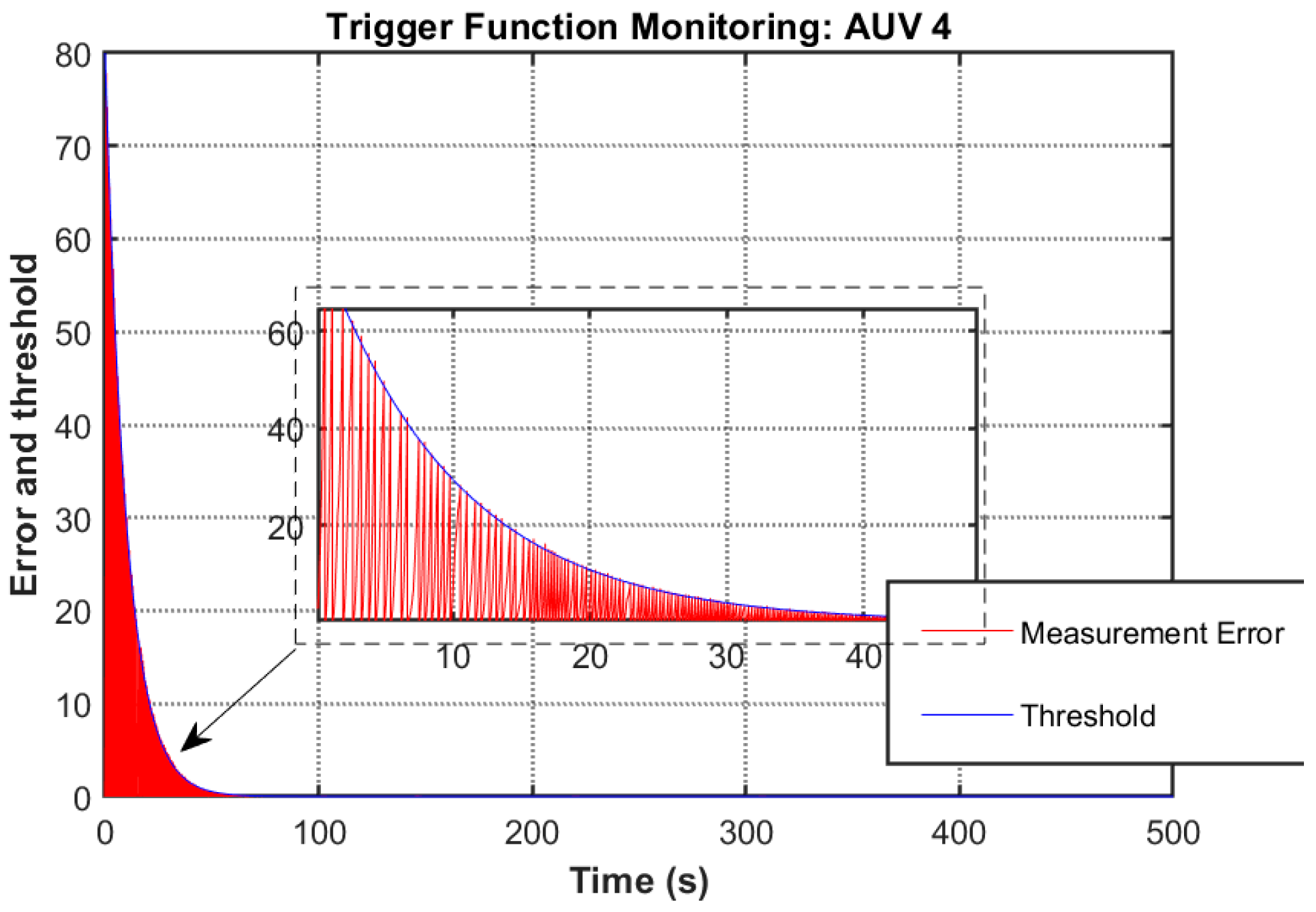
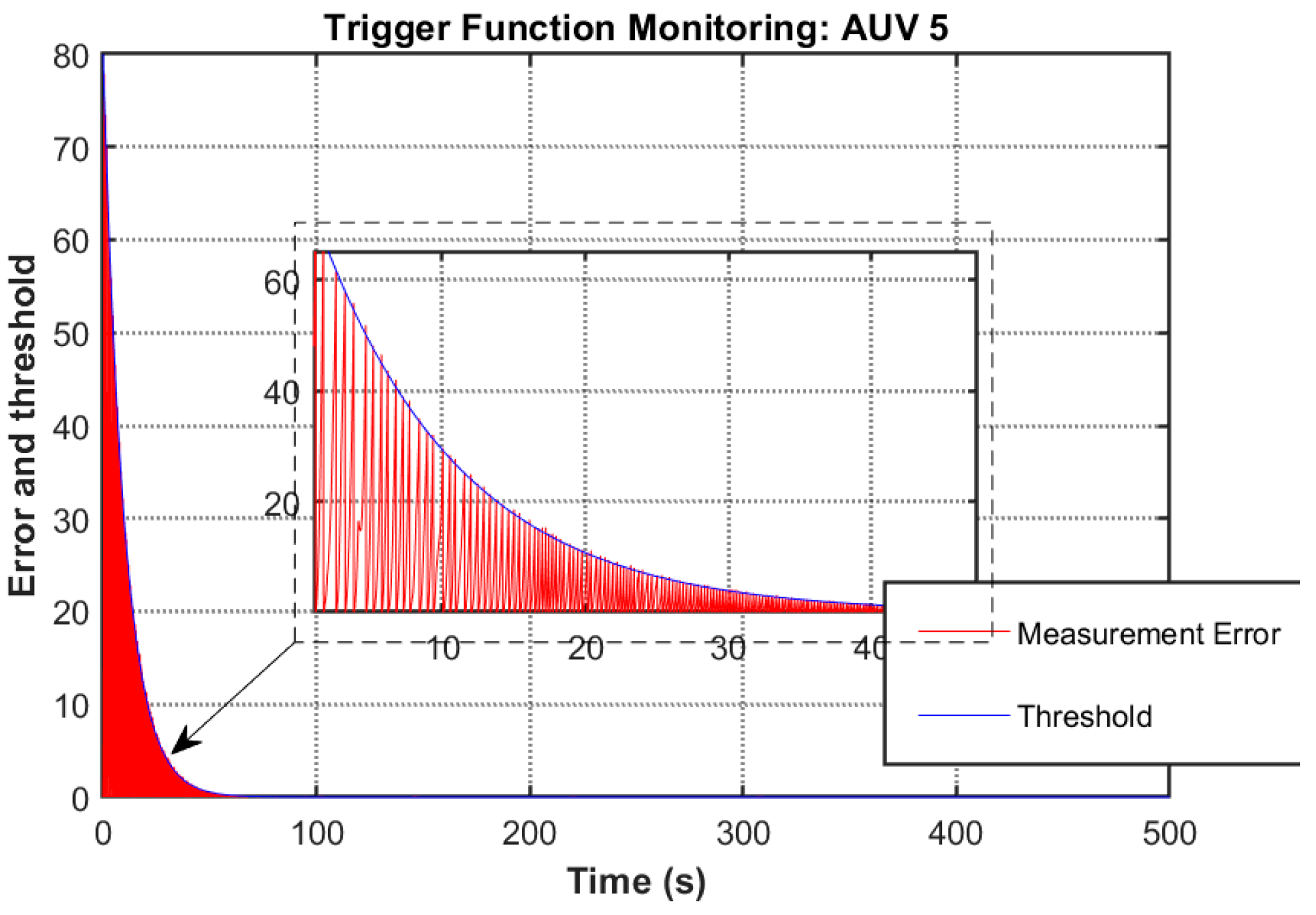
Figure 11 reveals the event-triggering mechanism’s effectiveness through comparative analysis of the triggering function and measurement error. The absence of triggering events outside prescribed execution intervals, coupled with a 96.5% reduction in communication frequency observed at t = 40 s (trigger counts: 137 (AUV1), 133 (AUV2), 149 (AUV3), 138 (AUV4), 135(AUV5)), substantiates the controller’s capability to minimize redundant data transmission and actuator updates through strategic intermittent control.
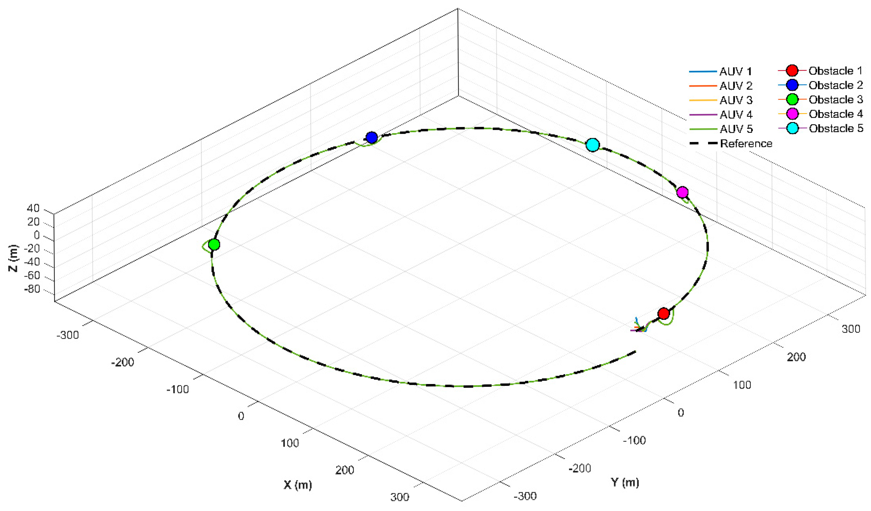
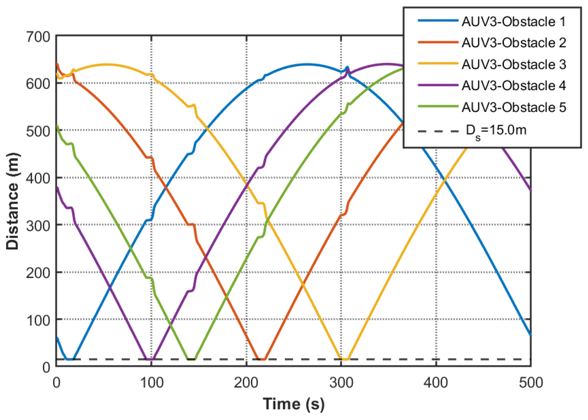
Implementation of the QP-based optimized controller yields distinctive behavioral patterns as shown in
Figure 12,
Figure 13,
Figure 14,
Figure 15,
Figure 16,
Figure 17,
Figure 18,
Figure 19,
Figure 20,
Figure 21,
Figure 22,
Figure 23,
Figure 24,
Figure 25,
Figure 26,
Figure 27 and
Figure 28. The coordinates of the obstacle are:
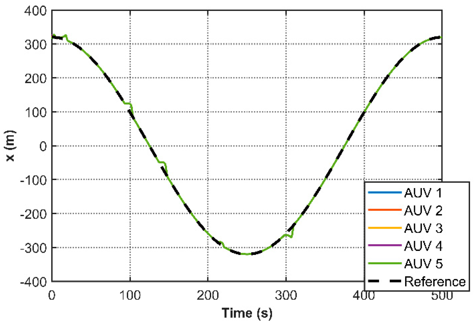
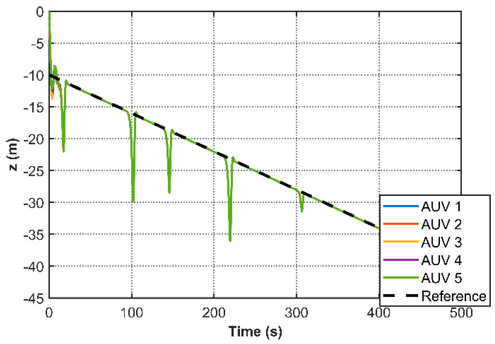
. State convergence characteristics (
Figure 12,
Figure 13,
Figure 14,
Figure 15,
Figure 16 and
Figure 17) and reconstructed 3D trajectories (
Figure 16) maintain nominal performance while introducing enhanced safety features. Due to the consensus-based nature of the controller, all AUVs are expected to converge to a common trajectory. Therefore, in the figures, the trajectories of multiple agents appear overlapped, which reflects the intended behavior rather than a lack of distinguishability. Critical obstacle avoidance capability is quantitatively verified in
Figure 19,
Figure 20,
Figure 21,
Figure 22 and
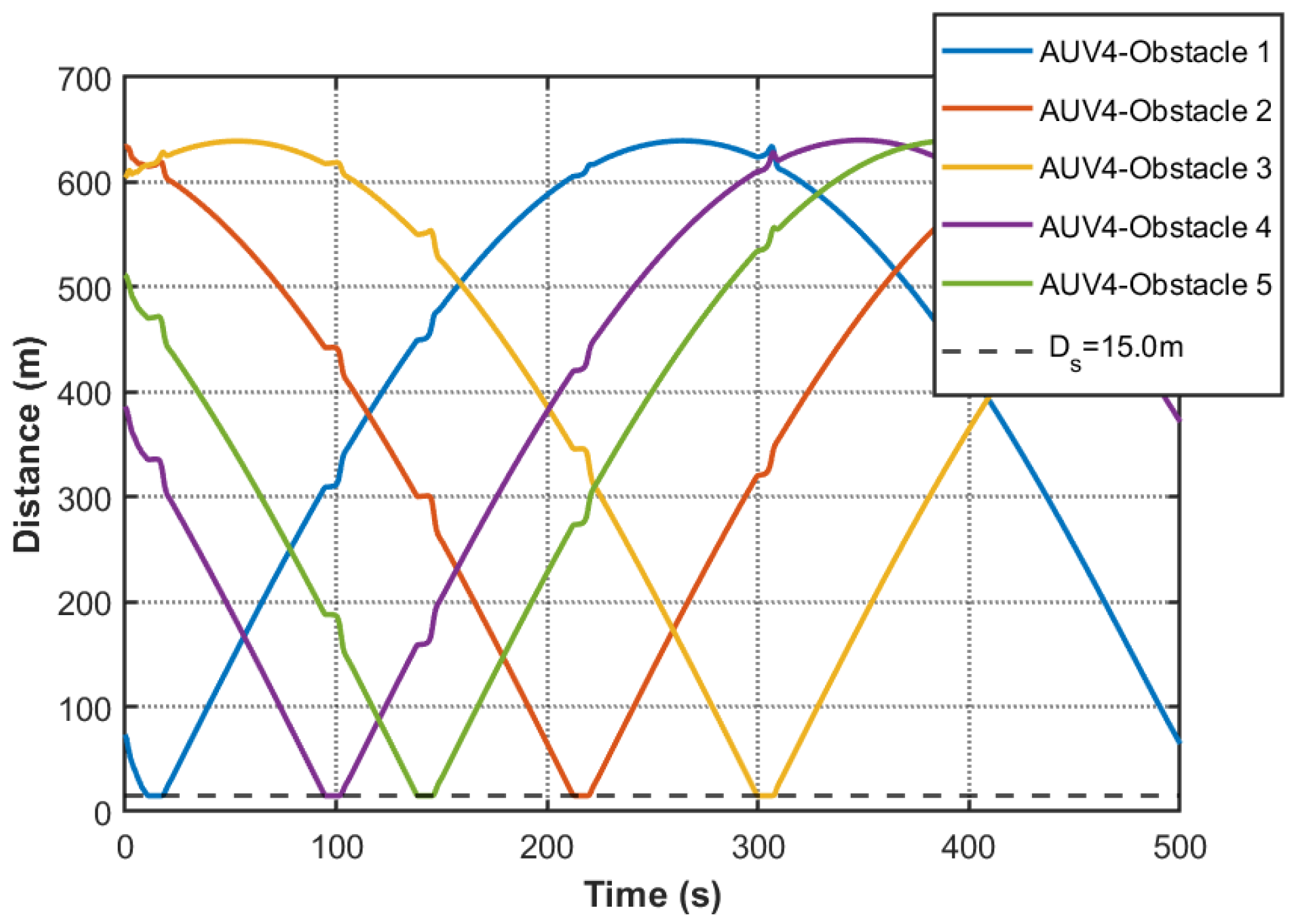
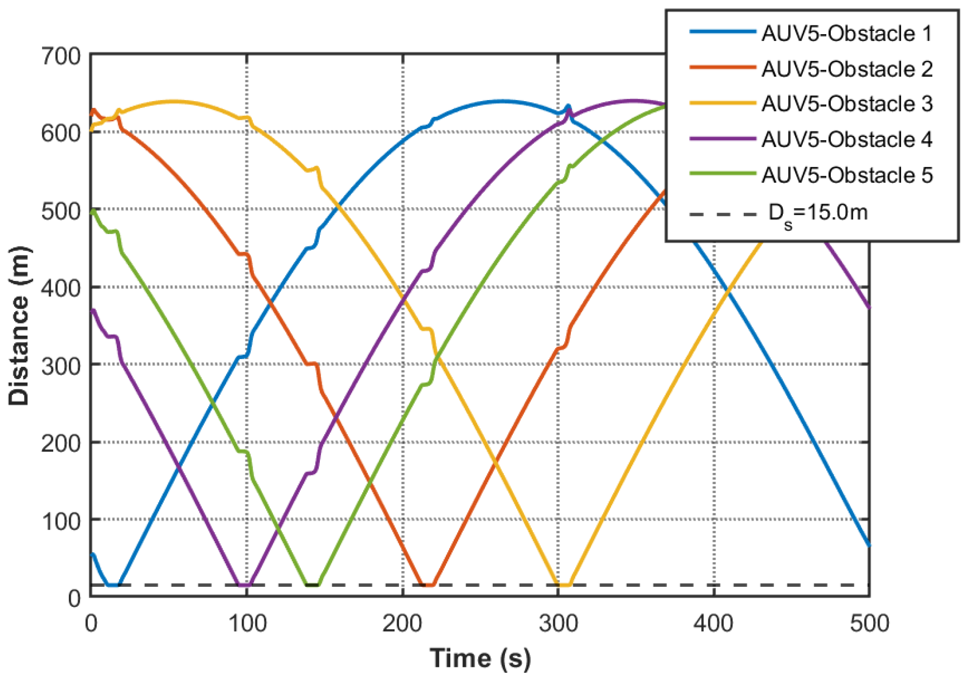
Figure 23 through minimum obstacle distance profiles. The safety-critical response exhibits prioritized obstacle avoidance maneuvers when obstacle proximity thresholds are breached (15 m), followed by rapid consensus recovery within 4 s, demonstrating effective integration of safety constraints without compromising coordination objectives. Comparative analysis of event-triggered mechanisms (
Figure 24,
Figure 25,
Figure 26,
Figure 27 and
Figure 28 versus
Figure 11) reveals architectural adaptations in the QP controller. The removal of fixed triggering intervals resolves potential hazardous situations during obstacle avoidance, although the trigger count increases by 19.1% compared to the nominal controller (trigger counts: 165 (AUV1), 161 (AUV2), 159 (AUV3), 164 (AUV4), 165(AUV5)). This dual achievement of persistent safety guarantees and communication efficiency enhancement constitutes a significant advancement over conventional event-triggered consensus protocols.
