Abstract
Recent advances in vision–language models (VLMs) have transformed the field of robotics. Researchers are combining the reasoning capabilities of large language models (LLMs) with the visual information processing capabilities of VLMs in various domains. However, most efforts have focused on terrestrial robots and are limited in their applicability to volatile environments such as ocean surfaces and underwater environments, where real-time judgment is required. We propose a system integrating the cognition, decision making, path planning, and control of autonomous marine surface vehicles in the ROS2–Gazebo simulation environment using a multimodal vision–LLM system with zero-shot prompting for real-time adaptability. In 30 experiments, adding the path plan mode feature increased the success rate from 23% to 73%. The average distance increased from 39 m to 45 m, and the time required to complete the task increased from 483 s to 672 s. These results demonstrate the trade-off between improved reliability and reduced efficiency. Experiments were conducted to verify the effectiveness of the proposed system and evaluate its performance with and without adding a path-planning step. The final algorithm with the path-planning sub-process yields a higher success rate, and better average path length and time. We achieve real-time environmental adaptability and performance improvement through prompt engineering and the addition of a path-planning sub-process in a limited structure, where the LLM state is initialized with every application programming interface call (zero-shot prompting). Additionally, the developed system is independent of the vision–LLM archetype, making it scalable and adaptable to future models.
1. Introduction
Recent advances in large language models (LLMs) and vision–language models (VLMs) have revolutionized the field of robotics [1], particularly in the areas of semantic navigation [2,3], common sense reasoning [4], direct planning by LLMs [5], and direct generation of code or policies for robot control [6,7]. Additionally, researchers are actively exploring methods to combine the reasoning capabilities of LLMs with the visual information processing capabilities of VLMs in areas such as state feedback, re-planning, and direct-action generation [8]. For example, DeepMind’s RT-2 has demonstrated real-time responsiveness and accuracy by integrating VLMs and robot trajectory data for end-to-end control [5]. However, existing studies are limited by scalability issues owing to the state memory maintenance of LLMs or reliance on external planners. There is also a lack of reliability owing to the absence of real-time sensor-based threat assessments and a lack of quantitative performance comparisons considering success rate, distance traveled, and time required [9,10,11,12,13]. Recent research has developed real-world, accident-driven test scenarios to evaluate safety-critical systems such as ADAS [14]. However, these scenarios remain confined to structured road environments and cannot be generalized to unstructured domains, such as the ocean surface.
To overcome these limitations, this paper introduces a dual-mode structure for path planning, threat assessment, and execution that provides explicit environment, sensor, and robot ability information through prompt engineering. This structure initializes the state at each call to enable stable inference and control. To validate this approach, we conducted navigation experiments using an autonomous marine surface vehicle in the Robot Operating System 2 (ROS2)–Gazebo simulation environment.
While previous studies have predominantly focused on the implementation of VLMs in terrestrial or indoor contexts, this investigation highlights two distinctive perspectives. First, it focuses on the application of VLMs in marine environments. Second, it delves into the architectural design imperative for operations under dynamic and memoryless conditions. Rather than serving as a mere proof of concept, the proposed system utilizes a structured control framework in which perception, planning, and risk assessment are explicitly separated and reinitialized at every time step. This integration strategy facilitates robust zero-shot decision making in unstructured and uncertain maritime scenarios, demonstrating a novel approach to addressing the limitations of existing LLM/VLM-based control systems.
We adopt a zero-shot control structure that does not require LLMs or VLMs to be trained separately, making judgments based solely on the input prompts given at each time step. Unlike fine-tuning or memory-based structures, this approach can flexibly respond to various situations based on a fixed model and single invocation [15], making it suitable for real-world control systems with repeated state initializations [5,16]. To this end, we utilize the OpenAI’s GPT-4o model, which is accessed via the OpenAI application programming interface (API), within ROS2 nodes. This model was selected for its versatility, accessibility, and common-sense reasoning capabilities, which were cultivated through extensive large-scale internet-based training. The cloud-based API approach facilitates real-time, low-latency integration, simplifies authentication, and enhances security management, which is beneficial in experimental environments. However, this method initializes a new inference session at each call without retaining conversational memory, so an emphasis on effective prompt engineering is crucial to ensure consistent and reliable responses. Given the unpredictable nature of marine environments, our zero-shot method is particularly well-suited to scenarios in which pre-collected training data are inadequate to encompass all possible operational variables.
Experimental results demonstrate that the proposed model achieves an improved success rate of 73% compared with 23% for the conventional method of instant command generation without path planning. On average, the robot traveled 45 m in 672 s, and the standard deviation and variance were significantly reduced. This study demonstrates the scalability of zero-shot-based real-time control loops under state initialization constraints and the quantitative effectiveness of the path planning coupling method. We also analyze the efficacy and limitations of the sensor–LLM–ROS integrated structure, outlining a promising direction for the future development of robotics and AI control systems.
2. Background
Historically, underwater robotics research has relied on fixed control rules or reinforcement learning policies for path planning, and obstacle avoidance. However, these methods are vulnerable to environmental changes and are inflexible in situations that require high-level situational analysis or contextual judgment.
Marine environments are particularly harsh and volatile. Constant external forces from waves and currents, unreliable GPS signals, limited sensor utilization (e.g., cameras, LiDAR, and communications), and visual information distortion from surface reflections can significantly degrade autonomous navigation performance. These environments require the ability to interpret new situations and make judgments in the moment, rather than relying on learned policies [9,13,16].
Real-time responses and flexible decision making are essential for autonomous navigation in the maritime environment as a result of changing surface conditions and unpredictable obstacle placement. Therefore, systems that rely on fixed rules or historical data have a limited ability to achieve autonomy in the maritime environment. A judgment system with a dynamic reasoning structure that can adapt to various situations is essential [17,18].
In this study, we implemented a VLM control system using ROS2 and verified its performance in a marine environment using the Gazebo simulator. ROS2 efficiently interlocks various sensors, actuators, and algorithms using message-based communication and a modular structure. These modules are also highly portable in real-world robot platforms. Gazebo can accurately simulate complex water environments through wave propagation and float representations, making it effective for the low-cost, iterative verification of underwater robot navigation algorithms.
The entire control process was implemented using Python 3.11.12 code. Specifically, the generative pre-trained transformer (GPT) application programming interface (API) call method uses the OpenAI tool to perform zero-shot memoryless control. To this end, prompt engineering techniques were applied. Previous studies primarily used fine-tuning models or an accumulative context by utilizing an LLM’s state memory [10,16]; however, this approach is inefficient in robot environments that require real-time responses or repeated state initializations [12]. In contrast, this study uses a zero-shot approach that interprets the context and generates commands with a single prompt call, enabling real-time control without additional learning or state storage, which simplifies the structure of the control system and enables consistent judgment under various marine simulation conditions.
In summary, to the best of our knowledge, this study represents the first attempt to integrate situational awareness, reasoning ability, judgment, and motion planning processes into a real-time, zero-shot control system combined with an ROS integration framework and Gazebo ocean environment simulation. The proposed system was used to evaluate the performance of autonomous maritime surface vehicles, with a focus on analyzing differences in judgment performance based on path planning.
3. Methodology
In this study, we designed an autonomous navigation control system based on visual information to simulate the human piloting of an unmanned drone using camera sensors. The system consists of sensor nodes that collect and store environmental images, a VLM node that performs high-level situational judgment, and an ROS-based control module that converts judgment results into commands.
The sensor node stores an image and delivers it to the VLM, which analyzes the image to determine the current situation and generates a command in the JSON format. The ROS control node then translates commands into actions such as controlling thrusters.
To improve robustness, we added a path planning sub-process to the existing single-judgment structure such that the VLM could process the entire situation into a single judgment. This approach clearly separates the judgment phase, which is then processed stepwise.
Prior to target detection, the drone searches for the target, as shown in Figure 1, which illustrates the step-by-step process from image data acquisition to VLM-based situational awareness, target identification, and thruster control. This figure also shows the actual GPT logs when the target is not found. A command flow connects each step (looping) until a target is identified.
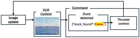
Figure 1.
System flowchart for the case where the target is not detected.
When the target is found, the drone switches to path-planning mode, as shown in Figure 2. Each step from image data collection to VLM-based situational awareness, target identification, movement planning, threat judgment, and thruster control is represented by actual GPT logs.
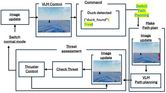
Figure 2.
System flowchart for the case where the target is detected.
Route planning and threat judgment are performed depending on whether a target has been identified. The drone then makes a path plan, follows the planned path, and transitions to the threat determination phase, which evaluates collision risk in real time. Combined with the ROS’s real-time control capabilities, this process increases processing efficiency and reliability. The following subsections describe the simulation environment and algorithmic details used to implement the proposed system.
3.1. Simulation Environment
To verify system performance, a three-dimensional water simulation environment based on ROS2–Gazebo was developed. In the Gazebo simulator, hydrodynamic elements were simulated to reflect the drift caused by ocean waves. Based on this simulation, the WAM-V unmanned surface vehicle model (see Figure 3) was placed in an environment with a camera mounted in front of the model.
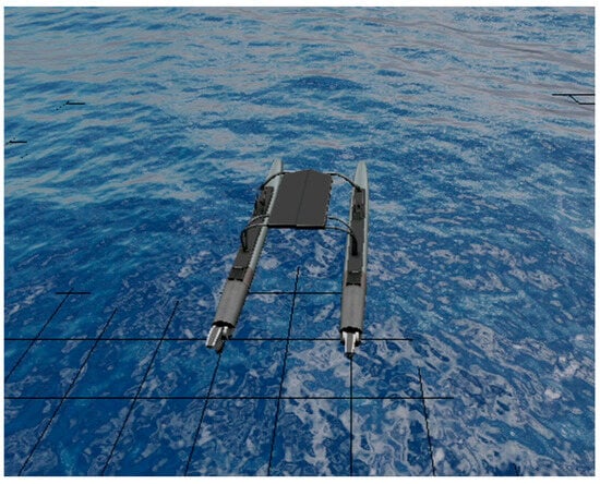
Figure 3.
Simple visualization of the simulation model WAM-V in the Gazebo environment.
The simulation environment contains buoy obstacles and targets of various colors. Specifically, there are three black, red, and purple buoys, a row of green rectangular buoys, and a yellow duck-shaped target (“Duck” model) on the water surface. To increase the realism of the underwater environment, wave and fluid dynamics plugins were added to subject the vehicle, obstacles, and buoys to waves. Figure 4 and Figure 5 present the simulation environment as a simple diagram and actual scene, respectively.
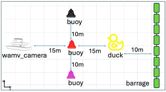
Figure 4.
Simple diagram of the simulation environment.
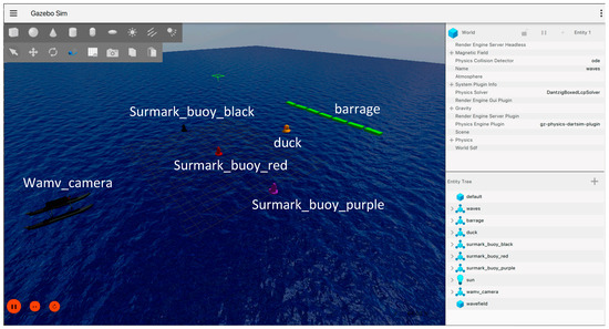
Figure 5.
Screenshot of the scene in the Gazebo simulation.
In this environment, the task of the vehicle (WAM-V) is to “find and approach a yellow duck while avoiding obstacles.” The simulation implemented camera data acquisition, data processing, command generation, and command execution, similar to a real physics-based system. An ROS2 node and Python controlled the entire scenario and were configured to validate performance under different conditions repeatedly (e.g., varying wave strength). This virtual environment was utilized to recreate complex and dangerous real-world underwater situations safely and to evaluate the performance of the proposed system iteratively.
In this study, the manipulated model was not controlled by output commands such as “move forward a certain distance” or “rotate a certain amount.” Instead, it was controlled by commands such as “apply a certain amount of force to the thruster.” As mentioned previously, in situations where GPS operation in the ocean is challenging, it can be difficult to command movement over a certain distance and confirm the results. To address this issue, commands of the above format were developed. Because all movements (i.e., forward, backward, and rotation) are controlled by applying a certain amount of force to the thruster, even if a stop command is issued to the thruster, the object will continue to move forward due to low friction, similar to sliding. If multiple forward commands are issued consecutively, the object will gradually move further forward.
LLMs and VLMs continue to encounter difficulties in predicting the current speed and the resistance between the object and fluid. We attempted to provide information regarding the object’s current speed in the prompts, but the VLM could not make correct judgments. Therefore, to verify the basic assumptions adopted in the experiment, the thrust value was adjusted to minimize the influence of wave-induced movements on the experimental results. Specifically, the thruster output was predefined to ensure that the wave-induced influence was not completely eliminated but also not so weak that the thruster output would be overshadowed by the wave-induced movement of the object. For forward and backward movements, the thruster parameter was set to 10, and for rotation, the parameter was set to 15. The thruster parameter was configured to operate for a predetermined duration (2 s) and then cease activity. The standard of two seconds was established to minimize the drone’s movement across the water surface due to low friction after minor movements.
3.2. Data Processing and Command Generation
The proposed system generates autonomous navigation commands based on images collected by camera sensors mounted on the front of the WAM-V model. Images are collected in real time, automatically saved at regular intervals, and encoded in the input format of the VLM (GPT-4o). During this process, OpenCV corrects the input images for radial distortion caused by lens curvature (e.g., refraction of the horizon) and tangential distortion, which can cause objects to appear sideways relative to their actual position. These corrections provide the VLM with more accurate visual information.
Stored images and predefined prompts are passed to the VLM to help interpret the current situation and determine the next action. All VLM invocations are performed using a zero-shot prompt, as shown in Table 1. In this format, the VLM receives new information and generates responses every second, without storing any memory. This process is called prompt engineering and provides the VLM with the necessary context and format to generate instructions such as “How should I move to find the target (duck)?” The autonomous driving commands outputted by the VLM are converted into a predefined format (e.g., {“decision”: “move,” “direction”: “W”}) and sent to ROS2’s thruster control node. The thruster control node receives the commands and controls the engine of the drone (thruster), turning and moving the vehicle. This cycle of data collection, judgment, command generation, and execution repeats periodically, forming a real-time closed-loop control structure in which the VLM updates the commands whenever new sensor images are received. The duration of this loop ranges from a minimum of 4 s to a maximum of 7 s. The loop’s operational speed is contingent upon the internet connection, VLM, and processing speed. The transmission and reception of data, issuance of commands, and control of the robot exert a lesser influence due to their operation on a timescale of milliseconds. Consequently, the entire loop is contingent upon the rapidity of the VLM’s image processing and command generation, with the exception of the 2 s operation time of the thruster.

Table 1.
Structure of the prompt for autonomous navigation decisions.
In the event that the VLM output format specified in Table 1 returns a JSON response with the “duck_found” property set to true, the model transitions to the path_plan mode. In this mode, the model generates a series of movement plans to approach the target. Previously, the model’s primary objective was to locate and navigate to the target within the image. However, in the path_plan mode, the focus transitions to recognizing the current situation based on the image and planning subsequent steps.
As was the case previously, in the path_plan mode, prior information is initialized. Therefore, the prompt content includes basic drone information, along with information regarding the movement method, as illustrated in Table 2. Subsequently, the VLM employs this information to formulate a plan. The plan is generated by considering the current obstacle situation and the drone’s relative position.
Table 2.
Structure of the prompt for directional path planning.
Prior to executing the generated movement plan, the model performs a real-time update of the image, followed by analysis and prediction of collision risk with obstacles based on the current movement plan. The system then determines whether to proceed with the execution of the plan or to terminate the process. In the event of successful execution, the subsequent plan will be initiated following movement. Conversely, if the process is aborted, it will halt and return to the initial point of the loop. The system will then restart from the “duck_found” state, and the mission will resume to achieve the desired objective.
4. Experiments
A series of navigation experiments were conducted in the ROS2–Gazebo simulation environment to verify the performance of the proposed VLM-based autonomous navigation system. The experiments consisted of 30 replicate tests divided into two cases: with and without path planning. In the latter, the VLM simply decides the next move while processing an image. All experiments were conducted under the same simulation conditions and prompt settings.
The initial position of the drone and placement of obstacles were kept consistent across the experiments. The prompt configuration remained the same, except for the addition of the path planning logic, which minimized the influence of other factors. Each experiment was conducted within the simulation under conditions similar to those in the real world (e.g., waves and fluid physics). System performance was evaluated quantitatively, based on the following three metrics:
- Success Rate (%): the percentage of successful detections and approaches to the target (yellow duck) out of the total number of trials.
- Average distance traveled (m): average distance traveled by the drone from the starting point to the target point.
- Average time taken (s): the average time from the start of the mission to the determination of success or failure.
The success rate indicates the reliability of autonomous navigation, whereas the distance traveled and time taken reflect the energy efficiency and route optimization performance.
Criteria for Determining Success and Failure
An attempt was considered successful if the drone navigated to the target (the duck) without colliding with any obstacles, if the duck was located in the center of the front of the drone (between the engines), or if the drone made direct contact with the target. Figure 6 presents camera sensor images saved during successful attempts.
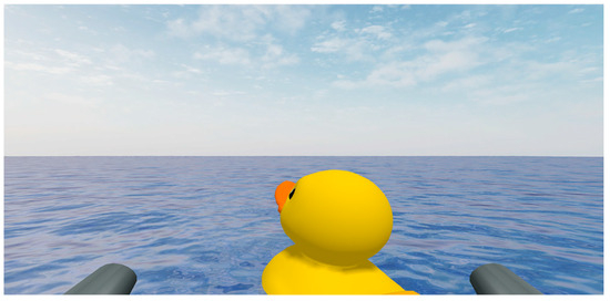
Figure 6.
Image captured by the camera installed in front of the WAM-V when it reaches the goal successfully (contact with the rubber duck).
Conversely, if the drone collided with an obstacle or failed to find the target, the attempt was judged a failure. In this case, the experiment ended early, and we proceeded immediately to the next iteration. Figure 7 presents a saved camera sensor image at the point of failure.
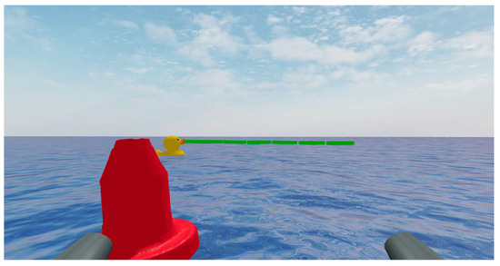
Figure 7.
Image captured by the camera installed in front of the WAM-V when it failed to reach the goal (contact with an obstacle).
5. Results and Analysis
We experimentally verified the validity of the proposed LLM control system implemented using ROS2–Gazebo. Experiments were repeated 30 times with and without the path-planning step. Metrics such as the mission success rate, average distance traveled, and time to target were collected and analyzed for comparison. The initial position of the drone, placement of obstacles, and structure of the prompts were kept consistent across all experiments, and only the logic related to path planning was added to the code, ensuring that variables other than the path planning effects were controlled.
- GPT single judgment
When the path planning step was omitted and the VLM generated commands based on a single judgment, it succeeded only 7 out of 30 times, resulting in a success rate of approximately 23%. This low success rate demonstrates clear limitations in terms of stability. However, the average distance traveled was 39 m and average time traveled was 483 s, representing relatively good performance in terms of path efficiency and judgment speed. This efficiency can be attributed to the unified command generation process and reduced computation and judgment times, which optimize the path of the VLM. However, entrusting the VLM with many judgments simultaneously was identified as a limitation that increased the mission failure rate significantly. Figure 8 presents the distance traveled and time to goal for the GPT single-judgment case.
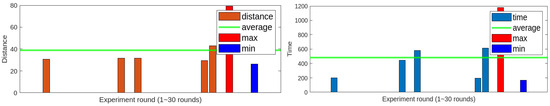
Figure 8.
Distance traveled and time to goal for the GPT single-judgment case.
This experiment involved repeatedly generating and executing a single command within a decision structure using VLM. This repetitive process was defined as a loop. The loop consists of three main steps: (1) the time from when the prompt containing the stored image is sent to the VLM until the response is returned; (2) the time it takes for the returned command to be transmitted to the ROS2-based thrust control node; and (3) the time until the command is executed as thrust. The process of receiving and storing image data was determined to be unrelated to the core judgment delay factor of the loop and was excluded from the calculation. Data from the image sensor is continuously received at 5 Hz. Storing and processing all frames would be excessive for real-time response speeds; therefore, the system is designed to store only one image approximately every seven seconds. Thus, the loop is defined based on the core decision making and control flow from image storage to command execution. This definition is used to analyze the average execution time and decision delay of the loop based on log data.
We analyzed the log data collected during the successful iterations of the GPT single judgment structure to calculate the average time taken in each loop stage. The log files record the timing of each event in milliseconds. We used these records to calculate three time elements. First is the time from when the image and prompt are sent to the VLM until the response is returned, referred to as “GPT latency time.” Second is the time from when the generated command is transmitted to the ROS2 thrust control node, referred to as “command transmission time.” Third, the time from when the command is transmitted to the ROS2 thrust control node until it is executed as thrust (referred to as “Thrust action time”). In each iteration, we measured the time intervals for these three steps and summarized the average, minimum, and maximum values for each element. Additionally, we calculated the total time required to complete the entire loop. Through this analysis, we can determine the proportion of each component in the overall loop time within the VLM-based decision–control loop and provide quantitative evidence describing the temporal distribution characteristics within the control structure.
The analysis results for each time element within the loop structure are shown in Figure 9 and Figure 10. First, Figure 9 shows that command transmission time and thrust action time have little effect on the total loop time. Command transmission time is measured in milliseconds and is negligible. Thrust action time, on the other hand, is fixed at approximately two seconds, depending on the control system design. Since these two elements do not contribute to the variability of the loop time, GPT latency time plays a crucial role in determining the overall loop time. Figure 10 shows the actual response delay time, GPT latency time, and overall loop time based on this analysis. GPT latency accounts for the largest proportion, averaging 4.2 s and constituting most of the loop time. Consequently, the overall loop time mostly falls within the range of 6 to 6.5 s, converging to an average of approximately 6.2 s. This can serve as an indicator when evaluating the periodic stability of the judgment and control loop in this experiment. It also suggests that the overall system control cycle is significantly influenced by the VLM response speed.
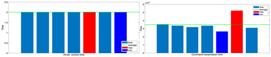
Figure 9.
Command transmission time and thrust action time in GPT single-judgment structure.
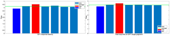
Figure 10.
GPT latency time and total loop time in the GPT single-judgment structure.
The most efficient results in the experiments were 29 m and 195 s. The path associated with this result is presented in Figure 11 and the corresponding time–velocity graph is presented in Figure 12. However, the large deviation between individual results makes the average value unrepresentative. The high efficiency values are also unrepresentative, and the overall stability is lacking as a result of the dispersion of paths and times.
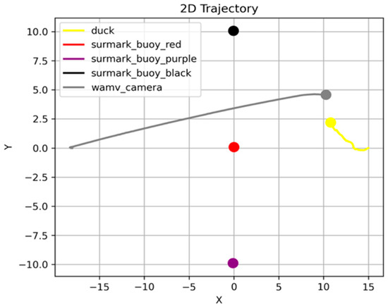
Figure 11.
Most efficient trajectory when the GPT makes a single determination.
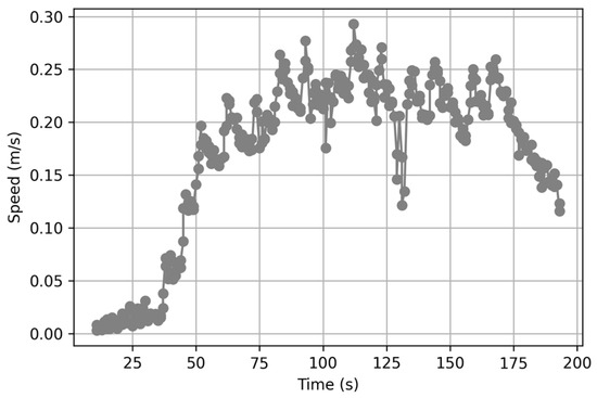
Figure 12.
Time–velocity graph of the most efficient trajectory when the GPT makes a single decision.
To better understand this variation, we analyzed the total loop time of the most efficient case, as shown in Figure 13. In this case, the command transmission and thrust control durations were consistent with previous averages, both recorded in the millisecond range and fixed at 2 s, respectively. Therefore, the variation in total loop time can primarily be attributed to fluctuations in VLM response time. This result shows that, even in successful trials, the latency inherent in VLM-based decision making affects control loop timing.
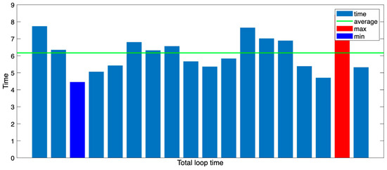
Figure 13.
Total loop time graph for the most efficient trajectory.
In summary, the GPT single-judgment structure is advantageous for making fast decisions but has a high failure rate in terms of collision avoidance and achieving the final goal, with poor overall consistency.
- GPT with path planning
Under the path planning condition, the system succeeded 22 out of 30 times with a success rate of approximately 73%. This result suggests that separating roles leads to more reliable and consistent decisions, even in a zero-shot structure where data are initialized with each call. However, the average distance traveled was 45 m and average time taken was 672 s. The average travel path was slightly longer and more time consuming than the condition without path planning.
This reduction in efficiency can be attributed to the separation of the judgment phase, which slows down command generation and route planning, leading to unnecessary detours. Attempts were made to record unusually long distances and times. When three outliers were excluded and the data were re-analyzed, the average distance traveled decreased to 40 m and average time decreased to 588 s. These results demonstrate that VLMs can be efficient and effective with the same input information when sharing roles, rather than generating commands with new information every second without path planning. This trend suggests that inefficiencies in certain environments or conditions may skew overall averages. The distance traveled and time to goal for the GPT with path planning are presented in Figure 14.
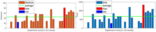
Figure 14.
Distance traveled and time to goal with path planning.
This experiment includes two loop structures, one of which is the same as the previous experiment. The first is a general GPT single judgment loop operating in the duck_found: false state. The second is a threat assessment loop operating in path planning mode after entering the duck_found: true state.
Since the decision loop prior to entering path planning operates under the same environment, prompt, and network conditions as the previously analyzed GPT single decision structure, separate time analysis is omitted. As confirmed by the actual experimental results, the average loop time is approximately six seconds, showing no significant difference, as represented visually in Figure 15.
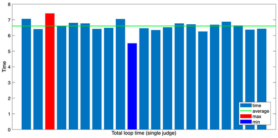
Figure 15.
Total loop time distribution of single-judgment mode (before path planning).
After switching to the path planning mode, the “threat assessment” loop begins to operate. This loop evaluates collision possibilities based on images collected before movement. If an obstacle posing a collision risk is detected on the route, the current route is terminated, and the system returns to its initial state to generate a new route: “threat assessment → command transmission → control execution.” The threat assessment loop consists of a series of steps: “threat assessment → command transmission → control execution.” In this paper, the loop is defined as “VLM’s single call → command generation → execution,” which precisely aligns with the threat assessment loop. Therefore, it is included as an object of time analysis.
The system environment in the current experiment is the same as in previous experiments. Therefore, the command transmission time is very small, measured in milliseconds, and has a negligible impact on the overall loop time. However, the thrust control node has a fixed two-second delay in command execution that remains consistent throughout the experiment, as shown in Figure 16.
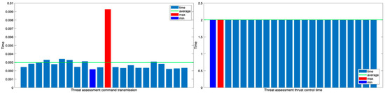
Figure 16.
Threat assessment thrust control and command transmission time graph.
Figure 17 shows the threat latency (the delay time in the threat assessment loop) and the total loop time. The average time required for the threat assessment loop is approximately 5.9 s, which is slightly shorter than the single judgment loop time of the GPT. This suggests that the response generation time is shorter because the threat judgment has a relatively simple structure and the response format is straightforward.
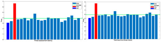
Figure 17.
Threat assessment latency and total loop time for threat check.
Meanwhile, the initial generation of the path plan is outside the scope of the loop defined in this paper. This is because it is a one-time event in which GPT makes multiple judgments and generates multiple commands in a single call. However, because the response delay in this step significantly affects the overall mission time, it was classified separately as a key indicator for analysis.
As shown in Figure 18, the average time required for path planning was approximately 3.7 s, slightly shorter than the 4.2 s average of the existing GPT single judgment loop. This suggests that, despite generating more complex responses, VLM operates efficiently thanks to its response optimization structure.
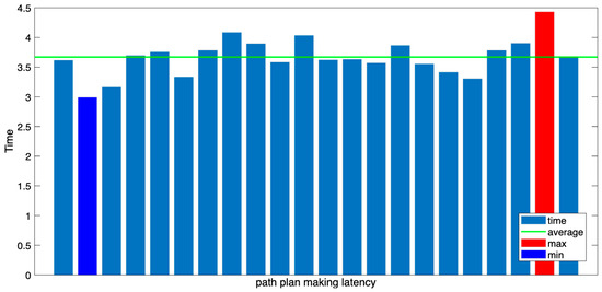
Figure 18.
Path plan making latency time.
The path planning mode’s loop structure consists of (1) an initial path-generation process based on a single call and (2) an iterative threat assessment loop. This structural advantage helps distribute the decision making burden and enhances navigation stability and reliability.
The most efficient result had a total distance traveled of 28 m and duration of 297 s. Figure 19 presents the corresponding travel path and the corresponding time–velocity graph is presented in Figure 20. Even within the constraints of the zero-shot structure, where the VLM state is initialized after each API call, the proposed system demonstrates more stable and consistent goal performance by implementing a path planning step. After incorporating the path-planning phase, the success rate significantly improved to approximately 73%. The average distance traveled and time required were reasonably good, except for extreme outliers. This result can be attributed to the ability of the VLM to perform each function, including situational awareness, route planning, and threat determination, separately and sequentially, which distributes the burden of judgment and increases the overall reliability of the system.
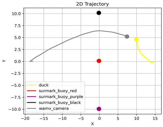
Figure 19.
Most efficient trajectory when the GPT utilizes path planning.
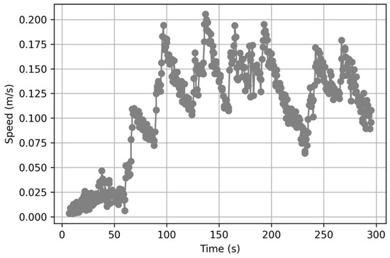
Figure 20.
Time-velocity graph of the most efficient trajectory when the GPT utilizes path planning.
The average path plan generation time measured in this experiment was approximately 3.4 s (Figure 21), and the average time of the threat assessment loop executed thereafter was 5.2 s. These results demonstrate a stable response speed (Figure 22).
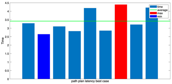
Figure 21.
GPT path plan latency (on the most efficient trajectory).
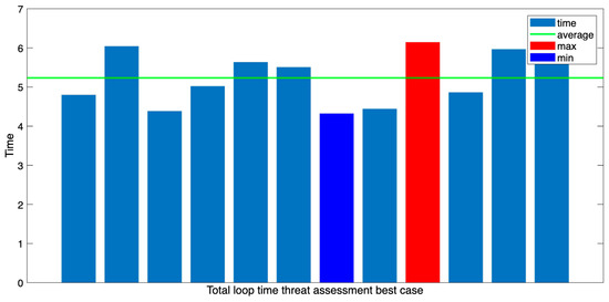
Figure 22.
Total loop time threat assessment (on the most efficient route).
These results suggest that the proposed structure reduces confusion in the decision making process and enables a rapid, situation-specific response by clearly separating path generation and threat assessment. These results demonstrate the potential of path planning–based decision making structures to operate robustly, even in complex environments.
Conversely, a structure in which the VLM makes judgments on the fly without path planning has advantages in terms of computational speed and efficiency. However, the large inter-experimental variation and low success rate indicate limitations in ensuring consistency and reliability. The integration of a time–velocity graph facilitates a more comprehensive analysis of the drone’s dynamic behavior. In the context of the path-planning mode, a discernible decline in velocity was evident in sections characterized by dense obstacles. This phenomenon can be attributed to the system design, where during the threat assessment phase, if a buoy is detected directly ahead, the current path execution is halted, and a new plan is generated. This phenomenon is readily apparent in Figure 23. The model, which was proceeding toward the buoy, encountered an obstacle and spent approximately 50 s re-generating and modifying the plan while performing a turn to avoid the obstacle. This delay resulted in the time–velocity graph dropping nearly to zero. If the newly generated plan does not meet the safety constraints, the system enters an infinite loop of stop-and-re-plan. Consequently, a substantial time investment is necessary to formulate a reliable plan, which results in prolonged mission durations despite enhanced reliability. This phenomenon frequently occurs during the path-planning phase, resulting in overall goal achievement times that are longer than those achieved with single judgment.
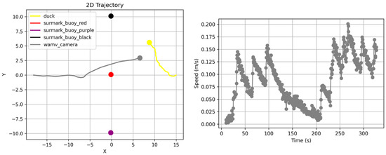
Figure 23.
An example trajectory and time–velocity graph during the path-planning phase experiment.
The majority of experiment failures were attributable to discrepancies between image-based inference outcomes and the simulation’s actual physical condition. During the process of inference, the drone and target both undergo slight drift due to low surface friction and the influence of waves, resulting in the captured images no longer accurately reflecting the current state. Consequently, the commands generated by the VLM based on the frame may not align with the actual situation, potentially resulting in collisions or navigation errors.
To address this challenge, the system has been engineered to update images for command generation periodically, incorporating straightforward obstacle avoidance protocols (e.g., methods for evading nearby buoys) within the prompts. However, cases were observed in which the VLM incorrectly prioritized target approach over obstacle avoidance during the decision-making process.
In such situations, the implementation of a rule-based avoidance system has been demonstrated to produce more consistent results. However, this approach is characterized by its inability to adapt to environmental changes and its struggle to respond flexibly in scenarios with complex obstacle configurations. The marine environment is in constant flux due to factors such as wind, waves, and reflected light. Consequently, methods based on general reasoning capabilities such as the VLM/LLM emerge as a more effective alternative.
A review of the experiment logs revealed numerous instances in which the VLM recognized partially obscured targets behind buoys as targets and subsequently initiated plans (see Figure 24). This finding suggests that the system may have engaged in judgment processes, even when confronted with incomplete visual information, employing shape inference and common-sense reasoning, rather than straightforward visual feature recognition. Conversely, when an obstacle is distant or distorted by waves or reflections, conventional object detection methods are prone to failure. However, VLMs have demonstrated an ability to generate stable and consistent navigation commands through general reasoning.
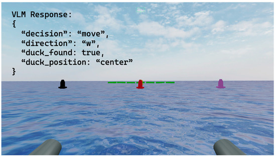
Figure 24.
Example images stored by the camera sensor during the experiment and some of the corresponding VLM logs.
These observations indicate that while a VLM is not a flawless system, it provides a flexible decision-making structure capable of adapting to new and visually ambiguous situations. This capacity may offer advantages over static rule-based systems in complex and unpredictable marine environments.
6. Conclusions
In recent years, research has been conducted to integrate VLMs and LLMs into robotic control and autonomous driving systems. Various attempts have been made to combine the visual-information-processing capabilities of VLMs with the higher-order reasoning capabilities of LLMs. However, most studies have focused on terrestrial environments. It is difficult to apply existing methods to dynamic and unstable marine environments such as surface and underwater environments because of factors such as waves, currents, communication delays, and sensor limitations.
To overcome these limitations, this study incorporated a path-planning phase into a VLM-based autonomous navigation system within the ROS2–Gazebo simulation environment. Additionally, a prompt engineering structure was designed that could be stably controlled in various environments in a zero-shot manner according to the changing marine environment. The proposed system consists of three stages: sensor input, judgment (GPT-4o), and execution (ROS2–Gazebo). It switches to navigation mode prior to target detection and then to path planning and threat assessment after detection. Each function is separated into stages to increase control stability.
Experimental results demonstrated that including the path planning step in the structure significantly improved the success rate of goal navigation, increasing it to 73% from 23% for the existing single-judgment structure. The results were stable and efficient in terms of the distance traveled and time required, except for a few outliers. Conversely, the single-judgment method had shorter average paths and faster judgment speeds but lower success rates and greater variation in results, which is disadvantageous in terms of experimental reliability. These results suggest that the proposed multilevel structural design plays a significant role in distributing the judgment burden, suppressing the VLM’s unstable responses, and improving judgment reliability.
The proposed system demonstrates that real-time autonomous navigation is possible in a zero-shot framework. In this framework, the state is initialized by calling the GPT using an API key in Python. A step-by-step prompt structure leads to environmental recognition, route planning, and threat assessment with clear role separation, demonstrating the applicability of VLM-based systems in unknown marine environments, where reinforcement learning or rule-based control is difficult.
Future research plans include extending the proposed structure to a real hardware environment and utilizing various sensor data such as LIDAR and IMU data to verify the performance of autonomous navigation in complex environments. This expansion will further improve the precision of real-time situational judgments and contribute to the development of fully autonomous navigation technologies for marine vehicles. Although the current simulation environment assumes clean and consistent visual inputs, real-world sensor data is often subject to noise, distortion, and hardware malfunctions. Previous studies have shown that denoising techniques are crucial for making accurate data-driven predictions in transportation systems [19]. Therefore, future implementations should incorporate sensor error mitigation strategies or robustness enhancements to ensure stable, real-time inference in complex marine conditions.
Existing rule-based or YOLO-based detection systems generally rely on fixed threshold settings or pre-trained visual patterns, rendering them inflexible in responding to non-standard situations such as nonlinear external forces or visual information distortion commonly encountered in marine environments. For instance, a study on real-time USV obstacle detection using YOLOv4-tiny exhibited high accuracy (mAP 99.5%), yet it was reported that detection accuracy was influenced by variations in lighting conditions and complex environments [20]. Furthermore, various attempts have been made, such as YOLOv5 reinforcement detection techniques using GANs [21] and IR-RGB fusion-based multi-object tracking techniques [22], but all of these are limited to predefined object types and have limitations in adaptability when new forms of obstacles or targets appear. In contrast, the VLM-based structure proposed in this study distinguishes itself from existing approaches by enabling the recognition of new obstacles and targets and path planning through common-sense reasoning without prior training on visual patterns.
Author Contributions
Methodology, T.-Y.K.; data curation, T.-Y.K.; visualization, T.-Y.K.; writing—original draft preparation, T.-Y.K.; writing—review and editing, T.-Y.K.; writing—review and editing, W.-S.C.; supervision, W.-S.C.; project administration, W.-S.C. All authors have read and agreed to the published version of the manuscript.
Funding
This research was supported by a Korea Basic Science Institute (National Research Facilities and Equipment Center) grant funded by the Ministry of Science and ICT (No. RS-2024-00404564).
Data Availability Statement
The initial environment setup for the ROS–Gazebo framework employed in this research is accessible at the following link: https://github.com/IOES-Lab/AI-Control-Room-VLLM (accessed on 8 August 2025). This setup encompasses an ocean wave environment and a scene world featuring vehicles and obstacles that are pre-configured to run on Apple Silicon Macs.
Acknowledgments
The environmental setup utilized in this research drew upon the template provided by @srmainwaring, which can be accessed at the following link: https://github.com/srmainwaring/asv_wave_sim (accessed on 8 August 2025).
Conflicts of Interest
The authors declare no conflicts of interest.
Abbreviations
The following abbreviations are used in this manuscript:
| VLM | Vision–language model |
| LLM | Large language model |
| ROS | Robot operating system |
| GPT | Generative pre-trained transformer |
| API | Application programming interface |
References
- Vemprala, S.H.; Bonatti, R.; Bucker, A.; Kapoor, A. ChatGPT for robotics: Design principles and model abilities. IEEE Access 2024, 12, 55682–55696. [Google Scholar] [CrossRef]
- Dorbala, V.S.; Mullen, J.F.; Manocha, D. Can an embodied agent find your “cat-shaped mug”? LLM-based zero-shot object navigation. IEEE Robot. Autom. Lett. 2023, 9, 4083–4090. [Google Scholar] [CrossRef]
- Yokoyama, N.; Ha, S.; Batra, D.; Wang, J.; Bucher, B. Vlfm: Vision-language frontier maps for zero-shot semantic navigation. In Proceedings of the 2024 IEEE International Conference on Robotics and Automation (ICRA), Yokohama, Japan, 13–17 May 2024; IEEE: New York, NY, USA, 2024; pp. 42–48. [Google Scholar]
- Zhou, K.; Zheng, K.; Pryor, C.; Shen, Y.; Jin, H.; Getoor, L.; Wang, X.E. Esc: Exploration with soft commonsense constraints for zero-shot object navigation. In Proceedings of the International Conference on Machine Learning, Honolulu, HI, USA, 23–29 July 2023; PMLR: New York, NY, USA, 2023; pp. 42829–42842. [Google Scholar]
- Brohan, A.; Brown, N.; Carbajal, J.; Chebotar, Y.; Chen, X.; Choromanski, K.; Ding, T.; Driess, D.; Dubey, A.; Finn, C.; et al. Rt-2: Vision-language-action models transfer web knowledge to robotic control. arXiv 2023, arXiv:2307.15818. [Google Scholar]
- Yu, W.; Gileadi, N.; Fu, C.; Kirmani, S.; Lee, K.H.; Arenas, M.G.; Chiang, H.T.L.; Erez, T.; Hasenclever, L.; Humplik, J.; et al. Language to rewards for robotic skill synthesis. arXiv 2023, arXiv:2306.08647. [Google Scholar] [CrossRef]
- Liang, J.; Huang, W.; Xia, F.; Xu, P.; Hausman, K.; Ichter, B.; Florence, P.; Zeng, A. Code as policies: Language model programs for embodied control. In Proceedings of the 2023 IEEE International Conference on Robotics and Automation (ICRA), London, UK, 29 May–2 June 2023; IEEE: New York, NY, USA, 2023; pp. 9493–9500. [Google Scholar]
- Jiao, A.; Patel, T.P.; Khurana, S.; Korol, A.M.; Brunke, L.; Adajania, V.K.; Culha, U.; Zhou, S.; Schoellig, A.P. Swarm-GPT: Combining large language models with safe motion planning for robot choreography design. arXiv 2023, arXiv:2312.01059. [Google Scholar] [CrossRef]
- Gadre, S.Y.; Wortsman, M.; Ilharco, G.; Schmidt, L.; Song, S. Cows on pasture: Baselines and benchmarks for language-driven zero-shot object navigation. In Proceedings of the IEEE/CVF Conference on Computer Vision and Pattern Recognition, Vancouver, BC, Canada, 17–24 June 2023; pp. 23171–23181. [Google Scholar]
- Rajvanshi, A.; Sikka, K.; Lin, X.; Lee, B.; Chiu, H.P.; Velasquez, A. Saynav: Grounding large language models for dynamic planning to navigation in new environments. In Proceedings of the International Conference on Automated Planning and Scheduling, Banff, AB, Canada, 1–6 June 2024; Volume 34, pp. 464–474. [Google Scholar]
- Kuang, Y.; Lin, H.; Jiang, M. Openfmnav: Towards open-set zero-shot object navigation via vision-language foundation models. arXiv 2024, arXiv:2402.10670. [Google Scholar]
- Chen, J.; Li, G.; Kumar, S.; Ghanem, B.; Yu, F. How to not train your dragon: Training-free embodied object goal navigation with semantic frontiers. arXiv 2023, arXiv:2305.16925. [Google Scholar] [CrossRef]
- Wang, Y.J.; Zhang, B.; Chen, J.; Sreenath, K. Prompt a robot to walk with large language models. In Proceedings of the 2024 IEEE 63rd Conference on Decision and Control (CDC), Milan, Italy, 16–19 December 2024; IEEE: New York, NY, USA, 2024; pp. 1531–1538. [Google Scholar]
- Wang, H.; Wang, X.; Peng, Y.; Lou, X.; Lee, J. An investigation of ADAS testing scenarios based on vehicle-to-powered two-wheeler accidents occurring in a county-level district in China. Transp. Saf. Environ. 2024, 6, tdae013. [Google Scholar] [CrossRef]
- Bucker, A.; Figueredo, L.; Haddadin, S.; Kapoor, A.; Ma, S.; Vemprala, S.; Bonatti, R. Latte: Language trajectory transformer. In Proceedings of the 2023 IEEE International Conference on Robotics and Automation (ICRA), London, UK, 29 May–2 June 2023; IEEE: New York, NY, USA, 2023; pp. 7287–7294. [Google Scholar]
- Shah, D.; Sridhar, A.; Dashora, N.; Stachowicz, K.; Black, K.; Hirose, N.; Levine, S. ViNT: A foundation model for visual navigation. arXiv 2023, arXiv:2306.14846. [Google Scholar] [CrossRef]
- Lee, W.; Kim, T.; Choi, W. Autonomous navigation command generation system for underwater robots using LLM. J. Inst. Control Robot. Syst. 2024, 30, 1191–1196. [Google Scholar] [CrossRef]
- Yu, B.; Kasaei, H.; Cao, M. L3mvn: Leveraging large language models for visual target navigation. In Proceedings of the 2023 IEEE/RSJ International Conference on Intelligent Robots and Systems (IROS), Abu Dhabi, United Arab Emirates, 14–18 October 2023; IEEE: New York, NY, USA, 2023; pp. 3554–3560. [Google Scholar]
- Chen, X.; Wu, S.; Shi, C.; Huang, Y.; Yang, Y.; Ke, R.; Zhao, J. Sensing Data Supported Traffic Flow Prediction via Denoising Schemes and ANN: A Comparison. IEEE Sens. J. 2020, 20, 14317–14328. [Google Scholar] [CrossRef]
- Handayani, R.; Susilo, H.; Setiawan, F. Real-time Obstacle Detection for Unmanned Surface Vehicle Using YOLOv4-Tiny. J. Mar. Robot. Res. 2023, 12, 155–167. [Google Scholar]
- Ahmed, S.; Ryu, D.; Kim, M. Robust Maritime Object Tracking in Fog Using GAN-enhanced YOLOv5. In Proceedings of the International Conference on Robotics and Automation in Marine Environments, Thuwal, Saudi Arabia, 8–10 May 2023. [Google Scholar]
- Park, J.; Lee, H.; Choi, S. Multi-Target Tracking for Marine Surveillance Using YOLOv5 and IR-RGB Fusion. J. Mar. Control. Syst. 2024, 17, 22–34. [Google Scholar]
Disclaimer/Publisher’s Note: The statements, opinions and data contained in all publications are solely those of the individual author(s) and contributor(s) and not of MDPI and/or the editor(s). MDPI and/or the editor(s) disclaim responsibility for any injury to people or property resulting from any ideas, methods, instructions or products referred to in the content. |
© 2025 by the authors. Licensee MDPI, Basel, Switzerland. This article is an open access article distributed under the terms and conditions of the Creative Commons Attribution (CC BY) license (https://creativecommons.org/licenses/by/4.0/).