1. Introduction
Underwater sensor networks (UWSNs) have received increasing attention from researchers as a core technology enabling applications such as ocean environmental monitoring, resource exploration, and disaster warning. However, the environments in which they operate present numerous challenges, including high propagation delays, limited bandwidth, constrained energy resources, and unstable node positions. These challenges make it difficult to directly apply routing protocols from terrestrial or aerial networks [
1,
2]. In practical deployments, nodes often experience random drifting due to ocean currents and encounter difficulties in replenishing their energy supplies, which further exacerbates the uncertainty and instability of routing decisions [
3,
4]. Therefore, designing a routing protocol that balances local and global awareness and offers high energy efficiency and reliability is essential for improving the performance of underwater networks.
To address these issues, this paper proposes a routing strategy that integrates a dual-layer weight adjustment mechanism at the node and network levels. By adopting a cross-layer design approach, it incorporates physical-layer information, such as received signal strength and link stability assessment, to provide dynamic criteria for relay node selection. The system uses a non-clustered, hop-by-hop data forwarding scheme and leverages surface buoy nodes as supernodes for global coordination. This mitigates performance bottlenecks caused by node drift and uneven energy consumption, thereby improving the reliability and lifespan of data transmission across the network. Due to the random drift of some nodes caused by ocean currents and the high cost of maintaining clusters, this paper adopts a non-clustered, hop-by-hop communication model. Relay nodes perform leap-based forwarding, while surface buoys serve as supernodes responsible for global broadcasting and data collection. Buoy nodes can store the collected information and transmit it to unmanned aerial vehicles (UAVs).
This research incorporates cross-layer information from the physical layer into the network layer. Nodes use the real-time received signal strength (RSS) obtained at the physical layer as a local evaluation metric and dynamically integrate it into the relay node selection strategy at the network layer. Additionally, during data forwarding, nodes use power control at the physical layer to select appropriate transmission power levelsto preven resource waste. The nodes also iteratively calculate a Link Energy Stability Factor to assess the long-term stability of the communication paths from a global perspective. This joint routing decision mechanism, which combines local link quality and global network stability, significantly improves the reliability of data transmission and reduces the retransmissions and control overhead caused by unstable paths, thereby enhancing the overall energy efficiency of the network.
To address the hotspot problem, this paper adopts a layered random node deployment strategy. Considering the high data traffic around the sink nodes, the network is designed to randomly deploy more nodes in regions closer to the sink. This deployment strategy effectively mitigates hotspot issues and reduces routing voids caused by local node energy depletion, thereby enhancing network stability and reliability. Moreover, the randomized distribution avoids excessive node concentration or sparsity, helping to balance the load and further extend the network lifetime. A mechanism for dynamically adjusting the reception range is also introduced, enabling nodes to handle directional data flows more efficiently, optimize relay node selection, reduce redundant forwarding, and alleviate communication congestion. To further reduce the communication overhead, this paper implements a dynamic power adjustment and listening mechanism. The traditional ACK mechanism is avoided during data forwarding. Nodes dynamically maintain their neighbor tables through data packets, eliminating the need for additional control packets, which not only reduces energy consumption but also improves the efficiency of network resource utilization.
The remainder of this paper is organized as follows.
Section 2 reviews the literature related to existing routing protocols for underwater acoustic sensor networks.
Section 3 describes the system model, including the network architecture and underwater acoustic channel modeling.
Section 4 presents the proposed routing protocol in detail, covering the packet structure, routing and neighbor table design, route initialization, relay node selection and update, and data reception procedures.
Section 5 evaluates the performance of the proposed protocol through simulations and analyzes the results.
Section 6 concludes the article, highlights its limitations, and discusses directions for future work.
2. Related Works
Location-Based Routing Protocols rely on the geographic positions of sensor nodes to make routing decisions, aiming to improve routing efficiency and reduce communication overhead [
5]. For instance, Xie et al. [
6] proposed Vector-Based Forwarding (VBF), which establishes a virtual routing pipe between source and destination nodes, allowing only nodes within the pipe to forward data. Although VBF reduces redundant transmissions, it suffers from packet delivery degradation in sparse networks due to communication voids and lacks path recovery mechanisms. To address these issues, Nicolaou et al. [
7] extended VBF by introducing Hop-by-Hop VBF (HH-VBF), which dynamically constructs local virtual pipes at each hop to improve robustness. However, this enhancement increases the computational and communication overhead, leading to higher delays and energy consumption. Similarly, Jornet et al. [
8] presented Focused Beam Routing (FBR), which uses directional beam control based on node and destination locations to adaptively forward data. Although effective in stable environments, the FBR’s reliance on precise location information limits its adaptability in dynamic underwater networks. Hwang and Kim [
9] proposed Directional Flooding Routing (DFR), which uses location and link quality to constrain flooding angles, improving delivery success and reducing void effects, but it still faces high energy costs and scalability issues. Wang et al. [
10] introduced the Energy-Balanced and Lifetime-Extension (EBLE) protocol, employing a cost function to select energy-balanced paths and extending network lifetime, showing superior performance in both regular and random deployments. Despite these advancements, location-based protocols generally depend on accurate positional information and struggle with sparse or dynamic topologies.
Location-Free Routing Protocols, on the other hand, do not require geographic position information. Yan et al. [
11] proposed Depth-Based Routing (DBR), a receiver-driven routing scheme that relies on depth comparisons between the node and the depth value carried in the data packet to make forwarding decisions, facilitating hop-by-hop progression toward the surface. Despite its simple structure and suitability for environments lacking location information, DBR can suffer from routing voids and concentrated energy depletion in sparse networks or areas near the sink nodes. To address these issues, subsequent protocols have been developed to optimize DBR. Wahid et al. [
12] improved DBR by introducing Energy-Efficient DBR (EEDBR), which selects forwarding nodes considering both residual energy and depth, aiming to balance energy consumption. However, EEDBR lacks multipath forwarding, resulting in higher error rates and limited load balancing in noisy multipath fading environments. Zhang and Cai [
13] further proposed Energy-Efficient Probabilistic DBR (EEPDBR), which integrates neighbor density alongside depth and energy, using a probabilistic forwarding mechanism to enhance robustness. The EEPDBR also incorporates two-hop neighborhood awareness to improve routing decisions. Despite these advances, the EEPDBR remains mostly localized and does not address global coordination or adaptive power control. Manal Al-Bzoor et al. [
14] introduced Adaptive Power Control Routing (APCR) to improve connectivity and energy use through dynamic transmission power adjustment. Later, Wang et al. [
15] proposed the APCDBRP, which combines power control with link-quality awareness based on received signal strength, balancing energy efficiency and load distribution. However, these protocols often consider either link reliability or power control, lacking a unified framework that jointly optimizes both across the networks. They also primarily rely on single-hop local information without global relay selection, which limits their adaptability and efficiency in dynamic underwater environments. In addition, Jin et al. [
16] proposed ERNC, a nonuniform clustering protocol that addresses energy imbalance and inefficient transmission through combined coordinate systems, residual energy, and node density metrics. Zhang et al. [
17] developed RLOR, a reinforcement learning-based opportunistic routing protocol that adapts routing paths dynamically based on node state to improve reliability and reduce delay. However, fixed parameters of the RLOR may reduce its adaptability to dynamic underwater environments. Dai et al. [
18] proposed a dual-hop topology-aware routing protocol, which effectively reduces the likelihood of packet voids and enhances both delivery success and energy efficiency. Inspired by this approach, we incorporated similar ideas into our protocol design to alleviate routing voids.
In addition to the aforementioned protocols, numerous recent studies have combined clustering architectures, hierarchical routing, opportunistic forwarding, entropy-driven mechanisms, and game-theoretic strategies to improve the energy efficiency, network connectivity, data delivery performance, and environmental adaptability of UASNs. The CAPTAIN protocol [
19] employs a hybrid communication model using intra-cluster optical and inter-cluster acoustic links to support data collection but does not account for ocean current dynamics or node mobility. To address energy loss and packet failures caused by environmental drift, Mei et al. [
20] proposed an ocean-current-aware adaptive routing strategy that can dynamically adjust routing paths to enhance robustness. From the perspective of opportunistic routing, Guan et al. [
21] proposed a distance vector-based opportunistic scheme that enables nodes to maintain multiple candidate forwarders, thereby improving robustness in environments with unstable links. Inspired by this idea, our work maintains a dynamic neighbor queue to preserve the multi-hop forwarding flexibility. The CELR [
22] constructs a hierarchical structure based on hop count and makes forwarding decisions by jointly considering the number of hops and residual energy, effectively mitigating routing voids while enhancing both energy efficiency and connectivity. Vahabi et al. [
23] developed a cluster-based depth source selection routing scheme that improves scalability in underwater environments, while Zhang et al. [
24] introduced an entropy-driven data aggregation strategy that reduces redundant transmissions and enhances efficiency. Additionally, Wang et al. [
25] designed a game-theoretic routing protocol that balances energy consumption and reliability in 3D UASNs by modeling node interactions as strategic games. Although these studies make notable contributions, most either focus on localized or single-layer optimizations while overlooking the constraints of limited energy and computational capacity inherent to underwater sensor nodes.
3. Network Architecture and Underwater Acoustic Channel Modeling
The underwater wireless sensor network (UWSN) designed in this study adopts a three-dimensional topology, forming a cross-domain architecture composed of underwater nodes, surface sink nodes, and aerial UAVs.
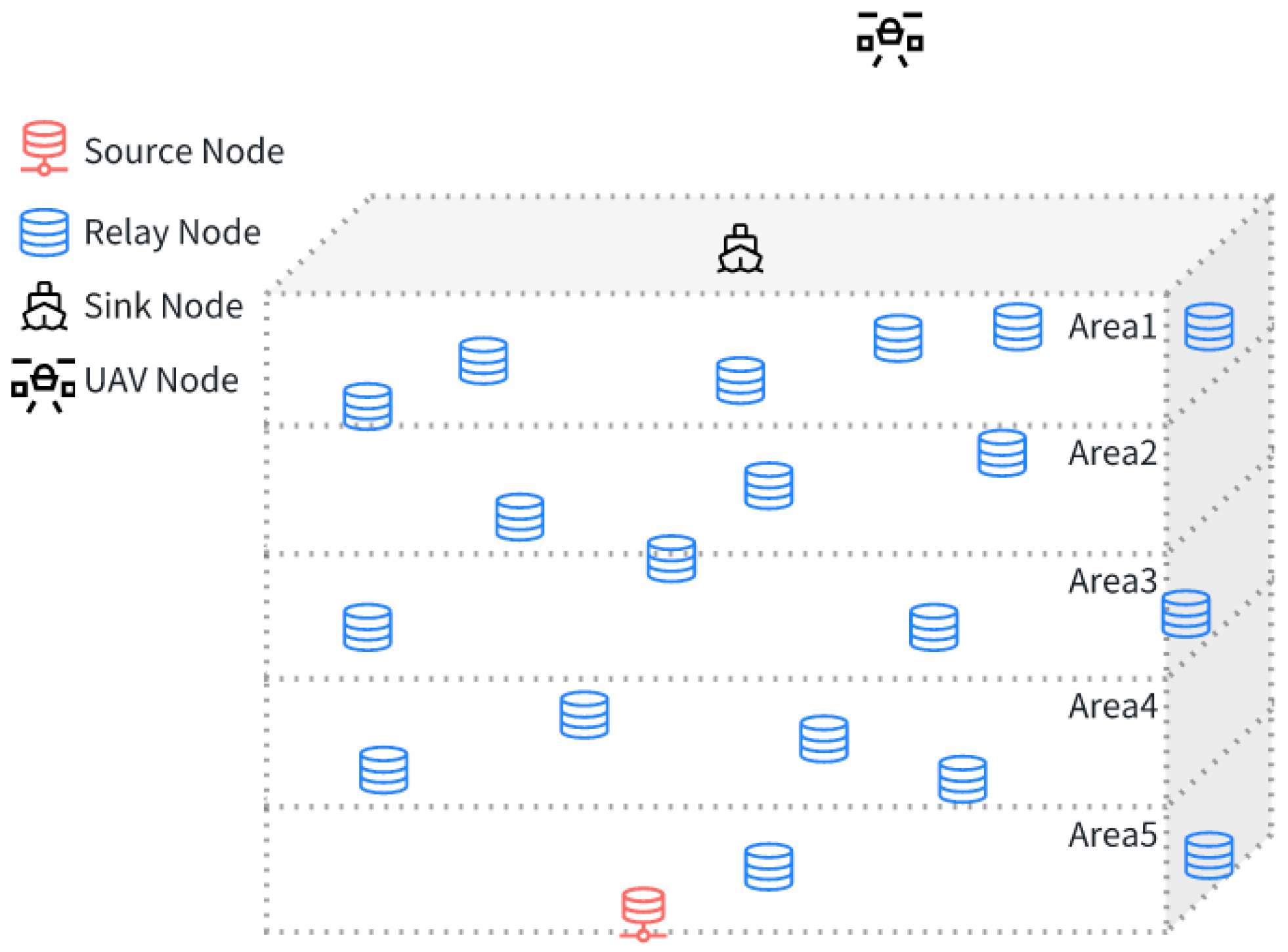
Underwater nodes are deployed at various depths and equipped with depth sensing and power control capabilities to support layered multi-hop acoustic communication. These nodes estimate the path loss using the received signal strength and adjust their transmission power accordingly. As shown in
Figure 1, the network architecture consists of source nodes, relay nodes arranged in depth-based layers, surface sink nodes, and aerial UAV nodes. Surface sink nodes act as gateways between the underwater and aerial domains, receiving acoustic signals from the underwater nodes and forwarding the data via radio. UAV nodes serve as mobile relays with flight mobility and communication capabilities. They collect data from multiple sink nodes, monitor network conditions, and transmit information to ground stations, thus supporting reliable data transmission and robust cross-domain coordination.
Underwater acoustic channels differ significantly from radio channels and represent one of the most challenging transmission media in communication systems. Compared with terrestrial radio channels, underwater acoustic channels feature slower propagation speeds, longer propagation delays, narrower available bandwidths, more significant Doppler effects, and more complex dynamic variations. The propagation speed of underwater acoustic signals is about 1500 m/s, which is only 1/200,000 of the speed of radio signals in air (approximately
). As a result, underwater acoustic communication experiences considerable propagation delays, making multipath delays and Doppler effects several orders of magnitude greater than those in radio communications. The attenuation of underwater acoustic signal power is caused by two main factors: geometric spreading and absorption, which can be expressed as
where
is the power loss in decibels,
is the spreading loss at distance d (in meters),
is the distance in kilometers, and
is the absorption loss at frequency
f (kHz) per kilometer (dB/km).
The spreading loss can be expressed as
where
k ∈ [1, 2] is an exponent describing the geometric spreading shape (analogous to the path-loss exponent in terrestrial RF models).
k = 1 corresponds to cylindrical spreading (e.g., when the water depth is much less than the horizontal range), and
k = 2 corresponds to spherical spreading (similar to free-space path loss in terrestrial systems). For frequencies above 700 Hz, the absorption loss is commonly computed using the empirically derived Thorp formula [
26] from oceanographic measurements:
The Thorp formula is one of the most widely used models for estimating absorption losses in underwater environments. In underwater acoustic environments, noise is typically caused by turbulence, shipping activities, surface waves, and thermal noise. In the reference unit of 1 μPa@1m/Hz, the power spectral density of these noise sources can be expressed as
where
s ∈ [0, 1] is the shipping activity factor (0 = low, 1 = high), and
ω is the wind speed (m/s) affecting the wave-induced noise. To ensure a realistic yet tractable simulation, we adopt moderate environmental conditions with
and
. The simulations are conducted within a three-dimensional deployment area of 1.5 km
3. Underwater acoustic channels exhibit dynamic variations in time, space, and frequency, rendering them complex and difficult to predict. Underwater acoustic channels vary dynamically in time, space, and frequency, making them complex to model. We used the AquaSimPropagation module from Aqua-Sim-NG [
27], which simulates propagation delay, multipath, path loss, noise, and Doppler effects. It includes Thorp’s attenuation formula and frequency-dependent absorption for realistic environmental modeling. Building on this, we incorporated ocean ambient noise to better reflect real underwater conditions. This combined modeling enables a more accurate evaluation of routing protocols in practical UWSNs.
4. Proposed Routing Protocol
This section begins with the network assumptions that form the basis of our protocol design, describing the network model and node capabilities. Subsequently, we detail the packet structure used for routing and data transmission. Subsequently, the routing and neighbor table structures are introduced to support efficient forwarding decisions. Next, we explain the route establishment process, including the relay node selection and route updating mechanisms that adapt to the network dynamics. Finally, the data reception procedures are outlined, completing the protocol-operation framework. Each subsection provides a clear and detailed explanation of the protocol components and their interaction.
4.1. Network Assumptions
Node Types and Roles: The underwater subnet includes source nodes, relay nodes, and surface buoy (sink) nodes. The source nodes are fixed, energy-rich, and computation-capable, and they collect environmental data. Relay nodes, cost-effective and energy-limited, forward data to sink nodes. Surface buoys with abundant energy serve as gateways to external networks. Energy heterogeneity exists: source and sink nodes are energy-rich, and relay nodes are energy-constrained.
Hardware Capabilities: All nodes feature power control modules and depth sensors. They estimated the path loss via the Received Signal Strength Indicator (RSSI, which measures the power level of a received signal) and adjusted the transmission power accordingly. Depth information aids routing decisions.
Communication Model: Relay nodes share uniform transmission power and range. Signal fading is symmetric in the uplink and downlink, allowing link quality estimation via the RSSI. The nodes support full-duplex communication.
Network Topology: Relay nodes are randomly deployed, forming a dynamic layered topology. The network was moderately scaled with sufficient density to maintain connectivity. Data flow hierarchically from the source to the sink.
Node Behavior: Nodes stop functioning when their energy is exhausted. To reduce the packet loss resulting from node failures or routing voids, each node maintains a dynamic neighbor table that is continuously updated based on recent communication activity, thereby avoiding the selection of unresponsive neighbors as forwarders.
4.2. Packet and Routing Table Structures
The APC-EEDBR routing protocol defines six packet types: Data Packet, Beacon Packet, Acknowledgment (ACK) Packet, Void Notification Packet, Probe Packet, and Probe Reply Packet. Each serves a specific function during the lifecycle of the network. Beacon packets are used in the initialization phase for neighbor discovery and path setup; data and ACK packets ensure reliable data transmission; probe, probe reply, and void notification packets contribute to link assessment, relay selection, and route adjustment. The packets included various fields related to energy, depth, neighborhood, and link quality. The meaning of each field is shown in
Table 1, and the composition of each packet type is summarized in
Table 2.
In the APC-EEDBR, packet structures are designed to suit the constraints of underwater sensor networks, including low bandwidth, high latency, and energy sensitivity, ensuring efficient communication with minimal overhead. Beacon packets periodically broadcast the node status to support neighbor maintenance and topology awareness. Data packets carry service content, along with routing and node information, for accurate forwarding. ACK packets confirm data reception, helping to avoid retransmissions and track energy use. The probe and probe reply packets obtain the real-time neighbor status to improve the path selection accuracy. Void notification packets report the forwarding failures and trigger route adjustments. Each packet type has a clear role in collectively supporting routing stability and adaptability.
The routing and neighbor tables together serve as the decision-making core of the protocol. The routing table stores the paths to the destination nodes, while the neighbor table tracks information about the adjacent nodes. Their integration enables efficient and adaptive routing in dynamic underwater environments.
The routing table (
Table 3) maintains essential routing information to support energy-aware and stable path selections. It helps nodes evaluate candidate paths based on energy distribution, link reliability, and network load balance, thereby improving routing efficiency and extending the network lifetime.
The neighbor table (
Table 4) contains detailed information about each neighbor, which is essential for evaluating the relay suitability and communication quality. Both the routing and neighbor tables are updated in real time through periodic control packets or upon receiving new datato ensure that they accurately reflect the current network state.
Table 4 elaborates on the structure referenced by the pointer field in
Table 3.
4.3. Routing Establishment
In underwater sensor networks, the routing setup is crucial for reliable data delivery. The process begins with the surface buoy node broadcasting a beacon at maximum power. The beacon includes key metrics such as depth, residual energy, neighbor density, average neighbor energy, and link stability. When a node receives a beacon, it checks whether the sender meets the neighbor’s criteria. If valid, it updates its neighbor table, estimates the optimal transmission power, calculates the forwarding probability, and updates the routing table. To propagate the information further, the node rebroadcasts its own beacon—also at maximum power—embedding its updated status unless the forwarding window has expired.
As shown in
Figure 2a, this top-down propagation continues until all nodes, including the source node, have updated their neighbor and routing tables, thereby completing the routing setup. Even nodes that are not selected as relays update their tables using the received beacon data, thereby improving the overall network awareness and robustness. To reduce the overhead, each beacon is forwarded only once within a limited time window. The detailed process is shown in
Figure 2b.
As shown in
Figure 2a, let node A receive a beacon from node B and measure the received signal power
in watts. For calculation purposes, the received signal level in decibels is defined as
:
Assuming the transmit power of node B is
, the path loss
between A and B (in dB) is given by:
This expression represents the attenuation of the signal during transmission. To ensure node B can successfully receive a signal, the minimum required receive power threshold is
. Then, the minimum required transmit power
from node A must satisfy:
Since practical communication devices typically support only a limited set of discrete transmission power levels, node A cannot transmit signals using a continuously adjustable power value
. To ensure that the receiving node B can successfully receive the data packet while minimizing energy consumption, node A should select the smallest transmission power level from the supported power level set that is not less than
denoted as
. The selection of the transmission power level must satisfy the following constraint:
where power levels represent the set of transmission power levels supported by the device.
where
is the packet length (in bits),
is the transmission rate (in bits per second).
4.4. Relay Node Selection and Routing Update
In the proposed scheme, each node dynamically selects the next-hop relay based on its current neighbor and routing tables upon receiving a data packet, as illustrated in
Figure 3. This on-demand routing avoids pre-defined paths and adapts to changes in topology and energy status. By combining local and global state updates, the proposed protocol ensures robust data delivery in dynamic underwater environments.
A probability-based relay-selection mechanism is adopted to enhance transmission reliability and energy efficiency. It considers multiple factors, including residual energy, neighbor density, average residual energy of neighbors, and Link Energy Stability Factor. This approach balances the network lifetime, delay, and energy consumption, selecting the next hop based on the forwarding probability derived from these metrics.
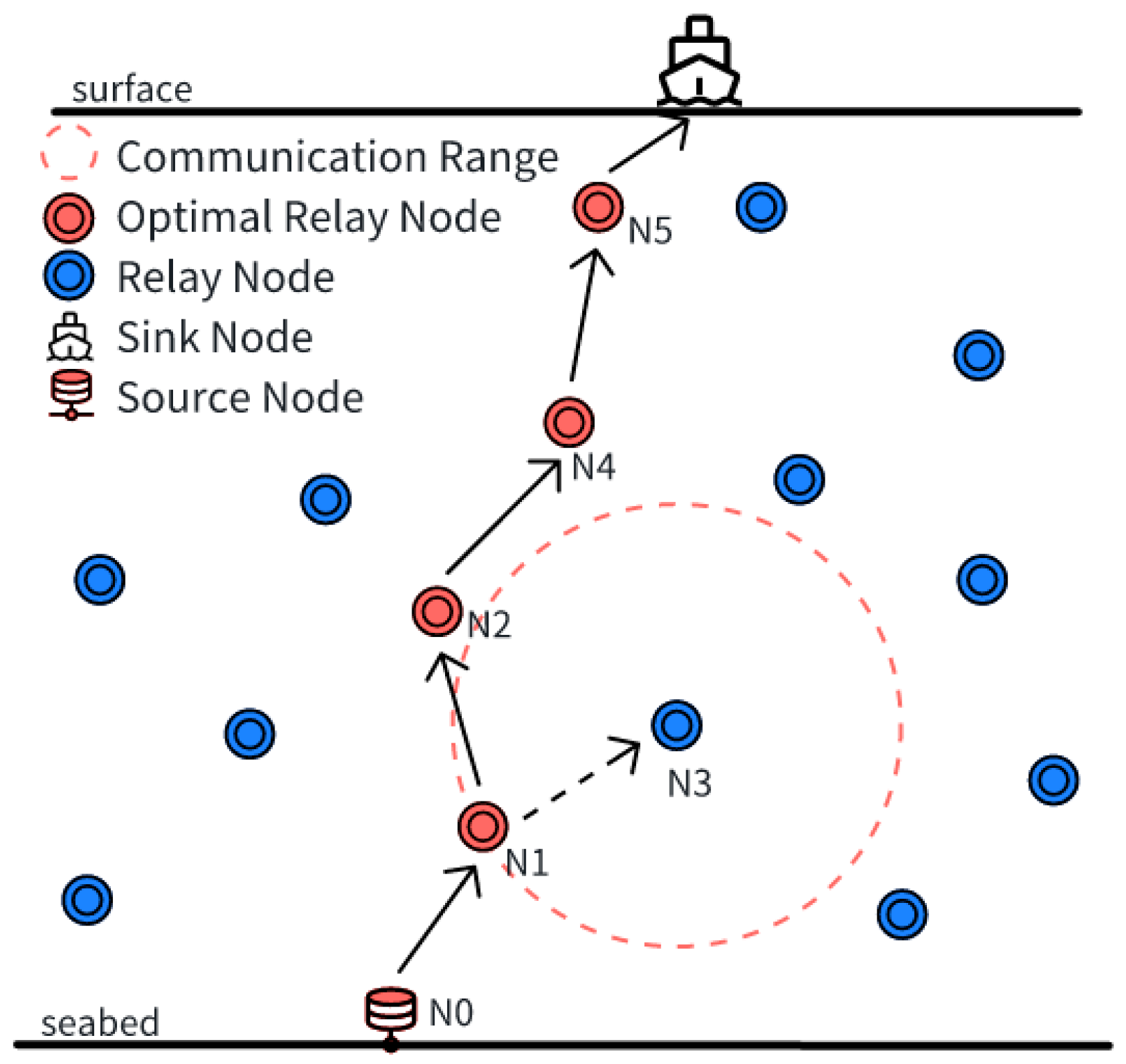
For instance, as shown in
Figure 4, node N1 may choose N3 over N2 based on energy metrics alone; however, if N3 has no neighbors at a shallower depth, a routing void occurs.
Inspired by the consideration of multi-hop link characteristics [
28] and the energy-aware void-avoidance strategy proposed in [
29], we introduce a Link Energy Stability Factor (LESF) that integrates both the energy status of neighbor nodes and the historical link quality, aiming to enhance routing stability and energy balancing. It is defined as:
where
adjusts the balance between current energy and historical stability, and
is the neighbor set of node
,
is the residual energy of neighbor node,
is the stability factor of neighbor. This mechanism enables routing decisions to dynamically sense the health of the surrounding nodes, avoid excessive load concentration, and significantly reduce communication voids caused by premature node failures. The overall relay-selection utility is
The first term, , represents the energy efficiency of transmission from node A to node B, as defined in Equation (9), with controlling the weight of communication quality. The second term, , represents the residual energy of node B, with determining the importance of energy awareness. The third term reflects the energy status of the neighbors by normalizing their residual energy relative to the network’s maximum energy, thereby assessing link stability. Parameters , control trade-offs among link quality, energy, and stability. The parameters are dynamically adjusted based on each node’s local information, including the energy status and neighborhood topology, to adapt to changing network conditions.
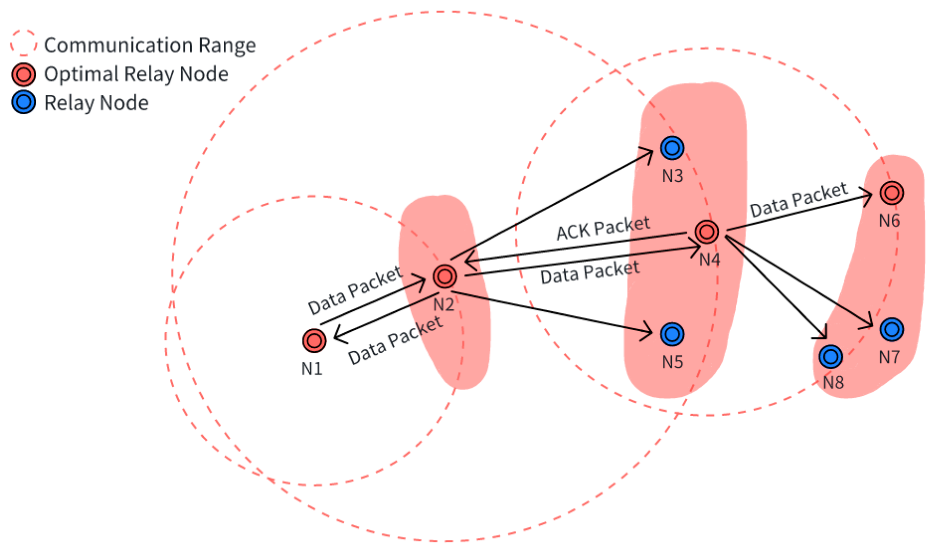
Upon receiving a data or control packet, the receiving node first measures the received signal strength and extracts the embedded information. If the sender exists in the neighbor table, the node updates its information; otherwise, it evaluates based on depth whether the sender qualifies as a next-hop candidate. If the criteria are met, the sender is added to the neighbor table; otherwise, it is discarded. In the proposed routing protocol, all packet types, except for void notification packets, can be used to update the routing information. In the proposed routing protocol, all packets (except void notification packets) can trigger routing table updates. As shown in
Figure 5, during data transmission, node N1 sends a data packet to its neighbor node N2. Upon receiving the packet, N2 uses the forwarding probability factors in its neighbor table to select the optimal next-hop node from the candidate relay nodes N3, N4, and N5—choosing N4. N2 then compares the transmission power required to send the packet to N1 and N4 and forwards the packet to N4 using the more energy-efficient option. Since N1 is within the communication range when N2 transmits to N4, N1′s reception of the packet can be treated as an implicit ACK from N2. At the same time, N3 and N5, although not the intended recipients are within N2′s transmission range and also receive the packet. These nodes, upon verifying that the destination ID does not match their own, simply update their neighbor tables and discard the packet. After receiving the data packet, N4 selects the optimal next-hop node N6 from its neighbors N6, N7, and N8 based on the forwarding probability factors and attempts to forward the data packet. However, because N2 is not within the transmission range from N4 to N6, it does not receive an implicit acknowledgment. To ensure reliable delivery, N4 adjusts its transmission power and explicitly sends an ACK to N2 after sending a data packet to N6. Additionally, during N4 the transmission to N6, node N8, although not the target recipient, also receives the data packet. It updates its neighbor table with the received information and then discards the packets.
4.5. Data Reception and Forwarding
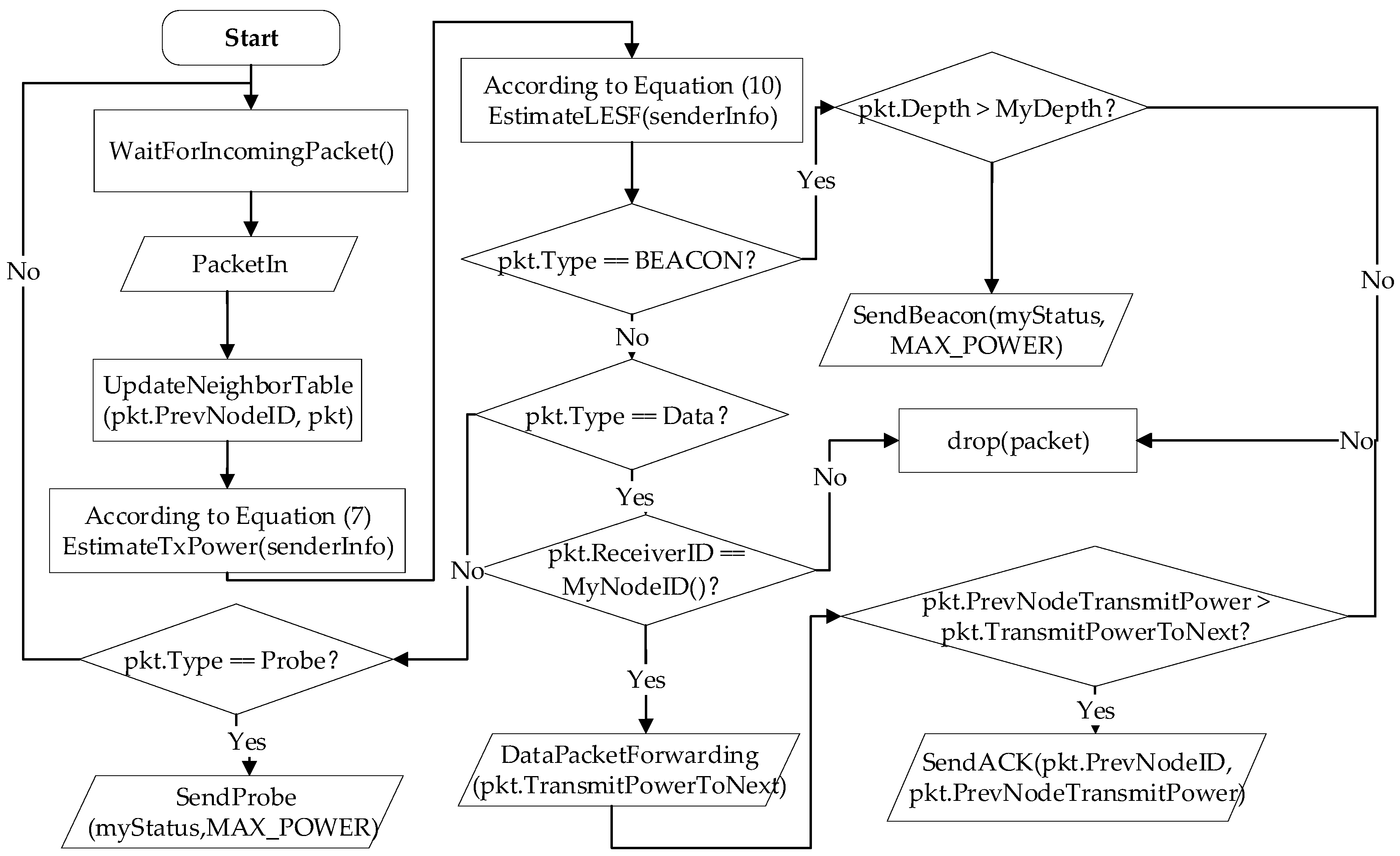
As shown in
Figure 6, in underwater sensor networks, a node receiving a data packet first checks whether it is the destination. If so, it accepts the packet, updates its neighbor table, and may act as a source or a relay. If not, it listens, updates the neighbor information, and discards the packet. For forwarding, it selects the best relay based on forwarding factors, transmits with initial power, and listens for ACK or forwarding behavior. If there is no response, the power gradually increases and retries. If unsuccessful, the relay is removed and a new one is selected. The non-selected neighbors monitor the process, update their tables, and may join the next relay selection, thereby improving the reliability and efficiency.
The dynamic power adjustment mechanism adapts to varying link conditions to ensure successful data transmission. The listening mechanism enables real-time monitoring of the transmission status. This design simplifies the data forwarding process, reduces energy consumption, and provides strong support for the efficient operation of underwater sensor networks.
5. Simulation Analysis
In this section, the performance of the proposed APC-EEDBR protocol is evaluated using the Aqua-Sim-NG [
27] simulation platform, which was validated in a prior work by Jafri et al. [
29], and compared with several representative protocols, including DBR [
11], EEDBR [
12], EAVARP [
30] and APCDBR [
15]. To support dynamic transmission power adjustment during data forwarding, we extended and modified the physical layer module in AquaSim-NG, enabling a more accurate simulation of the adaptive power control mechanism under underwater communication conditions.
5.1. Simulation Setup
A layered randomized deployment is used in the simulation, in which the area is vertically divided by depth. Shallow layers have higher node density due to stronger disturbances and heavier communication loads, while deeper layers allow sparser deployment to balance energy efficiency and coverage. Node mobility follows an improved model combining Ekman drift and two-dimensional random walk, with nodes moving horizontally at fixed depths and speeds decreasing with depth. Five surface buoys are fixed, the source node is placed in the deepest layer, and the relay nodes are randomly distributed across the layers. Routing is initiated by buoy broadcasts, and the source sends data every 40 s. To ensure practicality for resource-constrained underwater sensor nodes, the protocol limits per-node overhead by employing simple arithmetic for relay selection and adaptive messaging strategies. Nodes consume 0.1 W in reception, 1 mW in idle, and dynamically adjust transmission power between 1 and 10 W based on link conditions. Only selected relays initiate transmissions, with a maximum of three retransmission attempts if no ACK or forwarding behavior is detected, thus reducing unnecessary energy expenditure. The network lifetime is measured by the round in which the first node’s energy drops below 0.1 J, and the simulation ends when 2000 rounds are completed or 70% of the nodes fail. The simulation settings are presented in
Table 5.
5.2. Network Metrics
Network Lifetime: The network lifetime is defined as the time elapsed until the first sensor node exhausts its energy. It is measured from the start of the simulation to the round in which the first node failed. This definition is commonly used in energy-constrained underwater networks and has been referenced in prior work [
18]. The metric is computed as follows:
represents the start time of the simulation run, represents the time when the first node depletes its energy in that run, and is the total number of simulation runs.
Energy Consumption [
30]: The total energy consumption of the network during the simulation is defined as the difference between the sum of the initial energy of all relay nodes and the sum of their residual energy at the end of the simulation. It represents the overall amount of energy expended by all nodes to support the network operation. The formula is:
In the above equation, represents the initial energy of node , and is the remaining energy of node at the end of the simulation. denotes the total number of simulation runs.
Average End-to-End Delay: This metric measures the time required for a data packet to travel from the source node to the surface receiver, including transmission and queuing delays at intermediate relay nodes. This also applies to scenarios in which data flow from the receiver back to the source node. The average end-to-end delay is calculated as
represents the total number of data packets successfully received by the surface receiver; denotes the sending time of the data packet in the simulation run. denotes the receiving time of the data packet in the simulation run. is the total number of simulation runs.
The Packet Delivery Ratio (PDR) measures the efficiency of data delivery in the network and is defined as the ratio of successfully received packets at the surface receiver to the total number of packets generated by the source nodes. The formula for calculating the PDR is as follows:
is the number of packets successfully received by the surface receiver in the simulation run. represents the total number of data packets generated by the source node during the simulation run. denotes the total number of simulation runs. This metric effectively evaluates the robustness and reliability of the network when faced with real-world communication challenges, such as multi-hop relaying, noise interference, and packet loss.
5.3. Simulation Results and Analysis
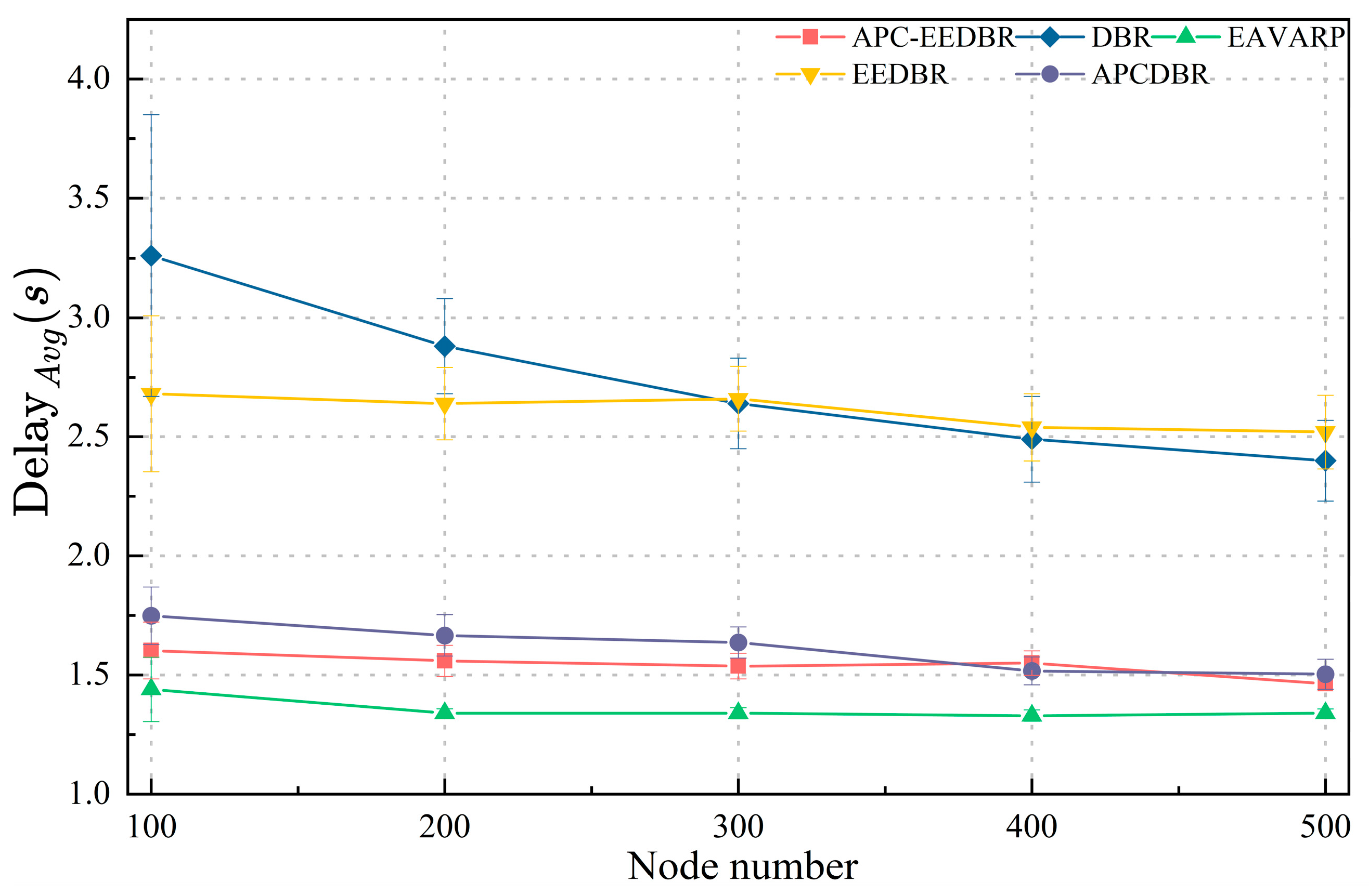
As shown in
Figure 7,
decreases as node density increases. EAVARP achieves the lowest delay by using opportunistic forwarding to avoid routing-voids. Although APCDBR reduces delay through energy and power control, the lack of explicit void avoidance can lead to retransmissions. In contrast, APC-EEDBR introduces link energy stability and dynamic weight adjustment, resulting in more reliable paths and fewer required retransmissions. DBR’s broadcast-based forwarding increases the delay, while EEDBR, although energy-aware, lacks adaptive path optimization.
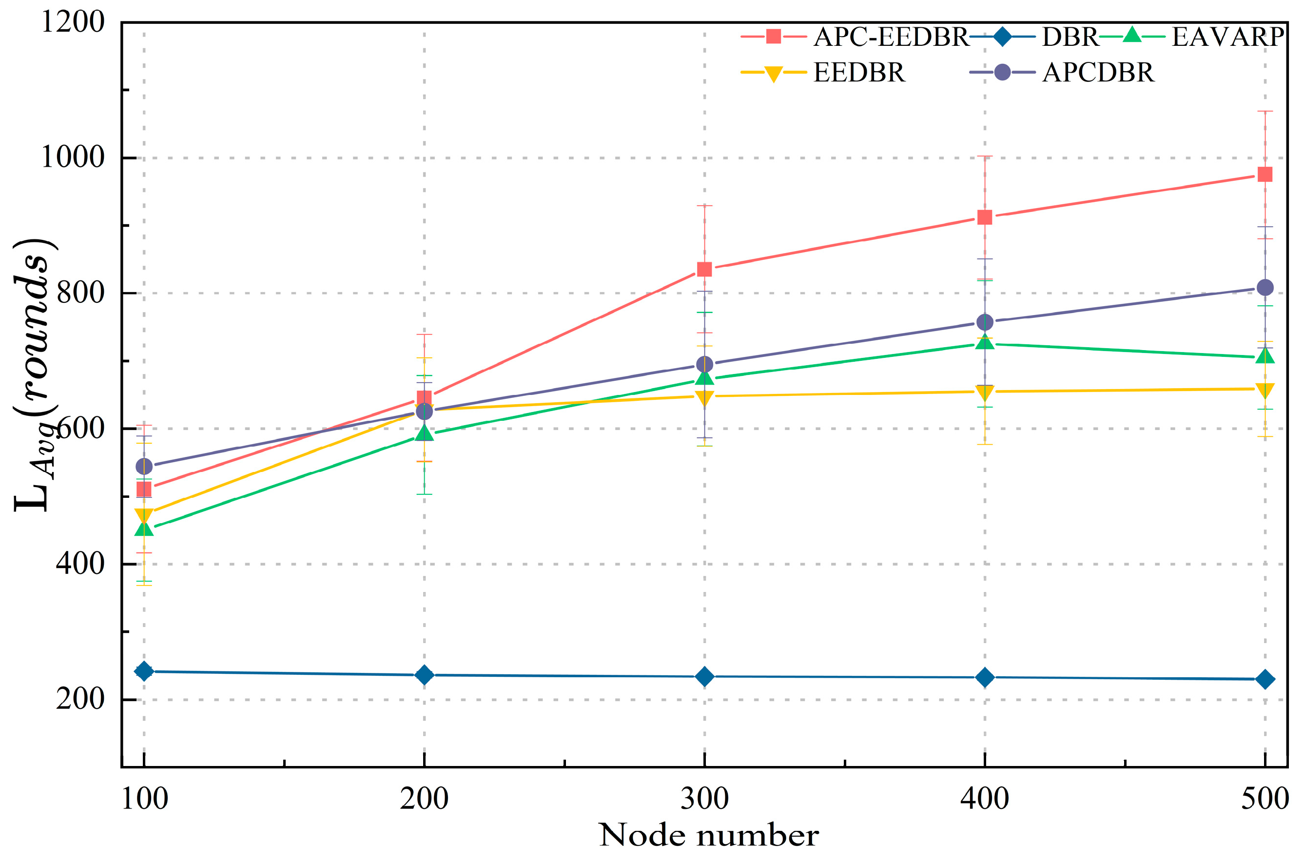
Figure 8 shows the impact of node density on
, defined by the round when the first relay dies. APC-EEDBR achieves the longest lifetime by combining energy awareness, power control, and link stability to balance the load and reduce energy waste. DBR quickly depletes energy due to redundant broadcasts. Although EEDBR and EAVARP offer some improvement, they lack effective balancing in dense networks. APCDBR considers energy and power; however, without void avoidance, it may select inefficient next hops, leading to early failures.
From
Figure 9, it is evident that with a fixed node count, APC-EEDBR exhibits slower node death rates and more gradual network degradation due to its power adjustment and energy balancing mechanisms. In contrast, the APCDBR fails to avoid routing voids, causing broadcast storms that increase energy consumption and accelerate node death. Similarly, DBR suffers from severe node overload, which leads to rapid early node failure. EEDBR and EAVARP also experience accelerated node deaths in the later stages due to an uneven forwarding load distribution.
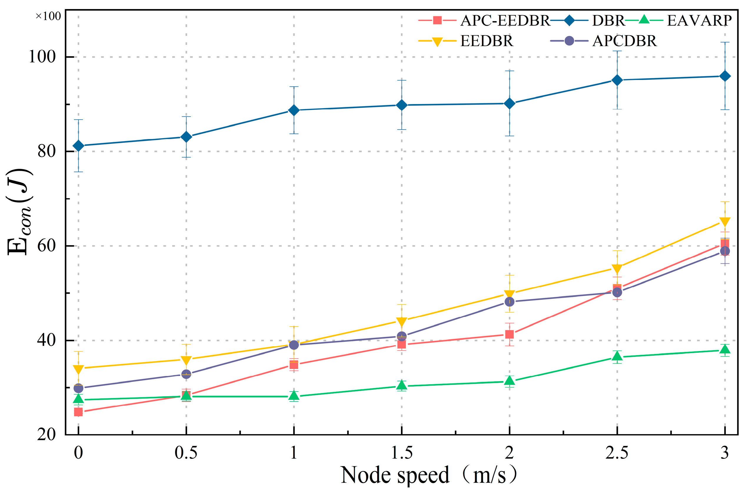
As presented in
Figure 10, in low-speed or static scenarios, the APC-EEDBR achieves lower energy consumption through energy awareness and fine-grained relay selection, demonstrating strong energy control capabilities. However, in high-speed scenarios, EAVARP exhibits more stable energy consumption and better per-packet energy efficiency. This is mainly due to the use of a fixed candidate set and energy balancing mechanisms, which effectively reduce the number of retransmissions. In contrast, the energy efficiency advantage of APC-EEDBR diminishes at high speeds due to the increased control overhead and frequent path updates.
Figure 11 shows that APC-EEDBR performs well at low speeds but degrades under high mobility due to control overhead and next-hop selection failures. DBR maintains a stable PDR owing to flooding, although it is energy inefficient. EAVARP and EEDBR both degrade rapidly due to rigid forwarder sets and weak link prediction. The APCDBR suffers from forwarding holes in the later rounds. These results highlight that all protocols face link instability under high mobility, and opportunistic routing could be a promising enhancement in such scenarios.
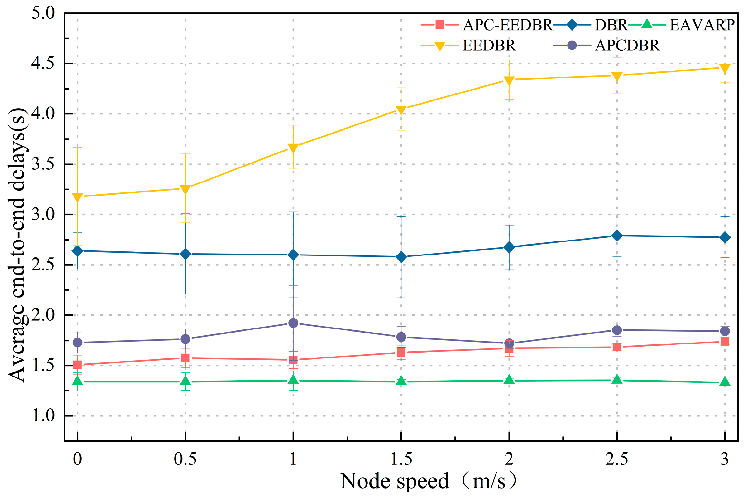
Figure 12 shows that as node speed increases, the
of APC-EEDBR shows a slight rise, indicating that it maintains good path adaptability and routing stability under dynamic topologies. DBR, which employs a stateless depth-based forwarding strategy, exhibits minimal delay fluctuations due to its low path maintenance overhead. However, it suffers from high redundancy and low efficiency. EAVARP maintains a relatively stable delay owing to its fixed path structure; however, it lacks a link quality feedback mechanism. In contrast, EEDBR experiences a significant increase in delay, reflecting the inefficiency of its path reselection mechanism under high-mobility conditions. The APCDBR exhibited moderate performance overall. However, due to the lack of explicit link void avoidance, it may trigger additional broadcast packets when voids occur, causing a slight increase in delay.
Table 6 compares the performance of the five routing protocols under medium node density (300 nodes) and medium mobility speed (1.5 m/s). The results show that APC-EEDBR achieves a well-balanced performance in terms of network lifetime, energy efficiency, and transmission reliability. In contrast, DBR exhibits a higher packet delivery ratio but suffers from higher energy consumption and shorter network lifetime. Future work will consider incorporating opportunistic routing mechanisms to further enhance the adaptability and robustness of the protocol in dynamic environments.
6. Conclusions
This study proposes and validates a novel routing protocol for underwater wireless sensor networks, Adaptive Power-Controlled Energy-Efficient Depth-Based Routing (APC-EEDBR), designed to overcome the limitations of existing protocols that rely solely on local information while neglecting global context and multidimensional factors, often resulting in unstable routing and uneven energy consumption. The APC-EEDBR protocol integrates multiple node-level metrics and introduces a globally aware relay selection mechanism combined with adaptive power control, thereby enhancing overall network coordination and adaptability. In highly dynamic underwater environments, where node mobility and frequent link disruptions prevail, APC-EEDBR currently lacks explicit mechanisms to mitigate increased control overhead and path instability. To address this limitation, future work should explore the integration of opportunistic routing strategies, wherein multiple candidate receivers participate in forwarding decisions. The actual relay node is selected on the receiver side based on the local link quality, residual energy, and link stability. This receiver-driven approach is expected to improve the robustness of the protocol under frequent topology changes.
In the future, underwater routing protocols are expected to evolve toward greater adaptability and intelligence, with a particular emphasis on mobility prediction, environmental awareness, and self-optimization. In addition, external factors, such as temperature variations and ocean currents, may impact acoustic signal propagation, introducing uncertainty into link estimation and control operations. Future improvements will explore solutions such as hybrid sensing methods, adaptive filtering techniques, and velocity-aware transmission power adjustment to further enhance the routing accuracy and network resilience in complex underwater environments. Furthermore, future work will focus on incorporating real-world measurements to improve the fidelity of underwater acoustic channel modeling, thereby enabling the design of more robust and effective routing protocols.


