Article

Unsteady Hydrodynamic Calculation and Characteristic Analysis of Voith–Schneider Propeller with High Eccentricity

1
College of Ship and Ocean, Naval University of Engineering, Wuhan 430033, China
2
College of Shipbuilding Engineering, Harbin Engineering University, Harbin 150001, China
*
Author to whom correspondence should be addressed.
J. Mar. Sci. Eng. 2025, 13(8), 1407; https://doi.org/10.3390/jmse13081407
Submission received: 13 June 2025 / Revised: 19 July 2025 / Accepted: 22 July 2025 / Published: 24 July 2025
(This article belongs to the Section Ocean Engineering)

Abstract

To analyze the hydrodynamic performance of the Voith–Schneider Propeller (VSP) under high eccentricity (e = 0.9), open-water performance numerical calculations were conducted for the VSP at different eccentricities. The results were compared with experimental data, revealing significant discrepancies at high eccentricity. Analysis identified that during the experiment, the VSP blades did not strictly move according to the prescribed “normal intersection principle” when passing near the eccentric point, which was the primary cause of the errors between the calculation and experiment. Further research demonstrated that when the blades pass near the eccentric point, both the individual blade and the overall propeller exhibit strong unsteady pulsation phenomena. The characteristics of these unsteady forces become more pronounced with increasing eccentricity. For the VSP under high eccentricity (e = 0.9), different Blade Steering Curves near the eccentric point were designed using a parametric method. The hydrodynamic performance of the VSP under these different curves was compared. The study demonstrates that rationally optimizing the motion of blades is a key approach to improving their hydrodynamic performance. At J = 2.4, the adoption of Opt-5 enables a 4.67% increase in thrust, a 25.19% reduction in thrust pulsation, a 12.74% reduction in torque, an 81.94% reduction in torque pulsation, and a 19.95% improvement in efficiency for the VSP.

1. Introduction

The Voith–Schneider Propeller (VSP) is a special type of marine propulsion device, consisting of a series of blades extending vertically from the hull bottom and uniformly distributed. While the blades revolve uniformly around the axis of the propeller disk, they simultaneously rotate around their own axes at variable speeds according to a specific law. Because the trajectory of the blades follows a cycloidal path, the VSP is also known as a cycloidal propeller. By altering the rotational angle of the blades during their cyclic motion, 360-degree vector thrust can be achieved. This mechanism combines propulsion and steering into a single unit, realizing “integrated propulsion and steering”. At low speeds, including zero speed, it maintains excellent maneuverability [1]. Consequently, the Voith–Schneider Propeller is widely used in ships due to its exceptional maneuvering performance, particularly suited for operations at low speeds or in confined waters [2].
In 1925, the Voith company of Germany developed the VSP, starting with the invention of a variable pitch type by an Austrian engineer named Schneider [3]. Subsequently, relevant scholars conducted theoretical and experimental research on the VSP. Taniguchi [4] proposed a quasi-steady model combining the momentum theorem to calculate the unsteady hydrodynamic performance of VSP blades. Haberman et al. [5], through comparison of calculated and experimental results, found that this method was only applicable when the VSP operated under conditions of low eccentricity and low advance coefficient. Zhu [6] improved the calculation accuracy by considering the influence of the blade curved trajectory, low-Reynolds-number effect, and stall on the lift coefficient, making it applicable for different eccentricities and the entire range of advance coefficients. Concurrently, Ficken and Dickerson [7] conducted a series of model tests, providing the most authoritative, noteworthy, and comprehensive test data concerning the VSP.
With the development of computer technology, viscous Computational Fluid Dynamics (CFD) numerical simulation methods based on solving the Navier–Stokes equations have been applied to the hydrodynamic numerical research of the Voith–Schneider Propeller (VSP). In the early 21st century, Voith [8,9] utilized COMET software to conduct research on the VSP. Through numerical simulation, the blade profiles of the VSP were optimized, leading to improved propeller efficiency. Bakhtiari et al. [10] employed a Genetic Algorithm (GA) to optimize the geometric parameters of the VSP (such as disk radius, chord length, span, and pitch ratio) to enhance hydrodynamic efficiency. After optimization, the efficiency of the VSP increased by 6.2% and 1.6% in OSV and VWT vessels, respectively. Li et al. [11] analyzed the influence of instantaneous forces and eccentricity on the thrust of the cycloidal propeller through numerical simulation. The study found that increasing eccentricity significantly enhances thrust but also intensifies thrust fluctuation, necessitating a balance between thrust and fluctuation during design. Sun et al. [12] investigated the hydrodynamic performance of a cycloidal propeller equipped with trailing-edge flaps. CFD simulations revealed that the combination of anti-virtual camber and sinusoidal motion could reduce lateral thrust and improve efficiency. Hu et al. [13] analyzed the hydrodynamic performance of the cycloidal propeller during maneuvering operations, finding that adjusting eccentricity can optimize the matching of thrust to the advance coefficient, reduce blade-to-blade interference, and improve efficiency. Liu et al. [14] compared the directional stability of thrust under a zero advance coefficient for two motion modes (VSP and Cyclorotor) using the CFD method. The research found that the Cyclorotor exhibited smaller lateral thrust fluctuation, more concentrated total thrust, and a more stable trajectory. Liu et al. [15] optimized VSP efficiency through parametric control of motion curves, employing a Radial Basis Function Neural Network (RBFNN) and Multi-Island Genetic Algorithm (MIGA). This approach achieved a maximum efficiency increase of 75% for a six-blade configuration at an eccentricity of 0.9.
In summary, the CFD method can simulate different blade geometric parameters and kinematic states, facilitating parametric studies for the numerical optimization of the Voith–Schneider Propeller (VSP). As the eccentricity increases, the interaction between the blades and the water flow intensifies, making the variation in their unsteady hydrodynamic performance worthy of further study. Therefore, this paper conducts unsteady hydrodynamic calculations and characteristic analysis of the VSP under high-eccentricity conditions. It investigates the influence of blade unsteady coupled motion on the VSP’s hydrodynamic performance by combining experimental comparison, analysis of the time-history characteristics of unsteady forces, and optimization of the Blade Steering Curve. The structure of the remainder of this paper is arranged as follows: Section 2 elaborates on the fundamental principles of the Voith–Schneider Propeller (VSP) and the numerical methods adopted in this study. It completes the motion and force analysis of the blades and conducts grid uncertainty analysis. Section 3 first presents a comparative analysis of unsteady hydrodynamics for the VSP at different eccentricities. Subsequently, based on the original curve corresponding to high eccentricity, it implements unsteady motion optimization of the blades using a parametric method and investigates the impact of different optimized Blade Steering Curves on the thrust, torque, efficiency, and hydrodynamic pulsation of the VSP. Section 4 summarizes the main findings of the paper.

2. Principles and Methods

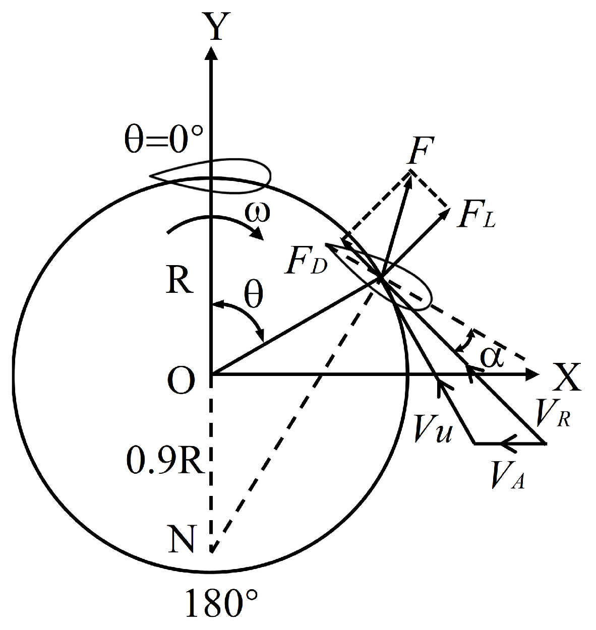
2.1. Working Principles

The Voith–Schneider Propeller (VSP) typically consists of 4–6 vertically mounted blades. While revolving uniformly around the center of the propeller disk, the blades simultaneously rotate around their own axes at variable speeds. Similar to the tail fin oscillation of fish, VSP blades undergo rapid flipping motion near a revolution angle of 180 degrees. As shown in Figure 1, point O is the revolution center of the propeller disk, R is the revolution radius, β is the self-rotation angle of the blade, θ is the revolution angle of the blade, and ω is the revolution angular velocity. As the vessel advances, the trajectory of the blades follows a cycloidal path. During rotation, the normal lines of all blade chord lengths consistently intersect at a single point [16], known as the eccentric point N. The ratio of the distance from the eccentric point to the revolution center ON - to the radius R is defined as the eccentricity, denoted as e = ON - /R.
According to the “normal intersection principle”, mathematical derivation yields the expressions for the self-rotation angle β and the self-rotation angular velocity ω β of the Voith–Schneider Propeller (VSP), as shown in Equations (1) and (2), respectively. Consequently, the variation curves of the blade self-rotation angle and angular velocity with the revolution angle, at a revolution speed of 300 rpm and eccentricities of 0.7, 0.8, and 0.9, are obtained, as illustrated in Figure 2. The blade self-rotation angle variation curve describes the instantaneous deflection angle of the blade while revolving with the propeller disk. Therefore, it is referred to as the Blade Steering Curve, abbreviated as BSC.
β = arctan e sin θ 1 + e cos θ = arcsin e sin θ 1 + e 2 + 2 e cos θ ,
ω β = d β d t = ω e 2 + e cos θ 1 + 2 e cos θ + e 2 ,
The Voith–Schneider Propeller (VSP) generates thrust through the interaction between its blades and the water flow. The velocity and force vector distributions acting on a blade are shown in Figure 3. VA is the inflow velocity, VU is the circumferential velocity of the propeller disk, and VR is the resultant velocity. FD is the drag force acting on the blade, FL is the lift force generated by the blade, and F is the resultant force. The angle of attack α is the angle between the blade chord line and the resultant velocity. Its relationship with the blade revolution angle θ is as shown in Equation (3). By moving the position of the eccentric point N, the magnitude of the angle of attack α can be altered, thereby changing the magnitude and direction of the thrust.
α = β arctan V A sin θ ω R + V A cos θ ,
The advance coefficient J is a key parameter for evaluating the hydrodynamic performance of a propeller. It is defined as the ratio of the distance advanced per revolution (VA/n) to the propeller diameter D, as shown in Equation (4).
J = V A n D ,
From the perspective of calculating the efficiency of the Voith–Schneider Propeller (VSP) (Equation (5)), for its special motion mode involving coupled revolution and self-rotation, the power consumption of both revolution and self-rotation should be considered simultaneously [17]. Therefore, the torque Q of the VSP should be the superposition of the revolution torque Qg and the self-rotation torque Qb [15], as shown in Equation (6).
η = T V A ω Q ,
Q = Q g + n b n g Q b ,
Here, ng and nb are the revolution angular velocity and self-rotation angular velocity of the blades, respectively. Non-dimensionalizing the thrust T and torque Q of the VSP yields its thrust coefficient KT and torque coefficient KQ, as shown in Equations (7) and (8), respectively.
K T = T ρ n g 2 D 3 L ,
K Q = Q ρ n g 2 D 4 L ,
Here, ρ is the density of water, and L is the blade span. Consequently, the formula for calculating the efficiency of the VSP is given by Equation (9).
η = K T K Q J 2 π ,

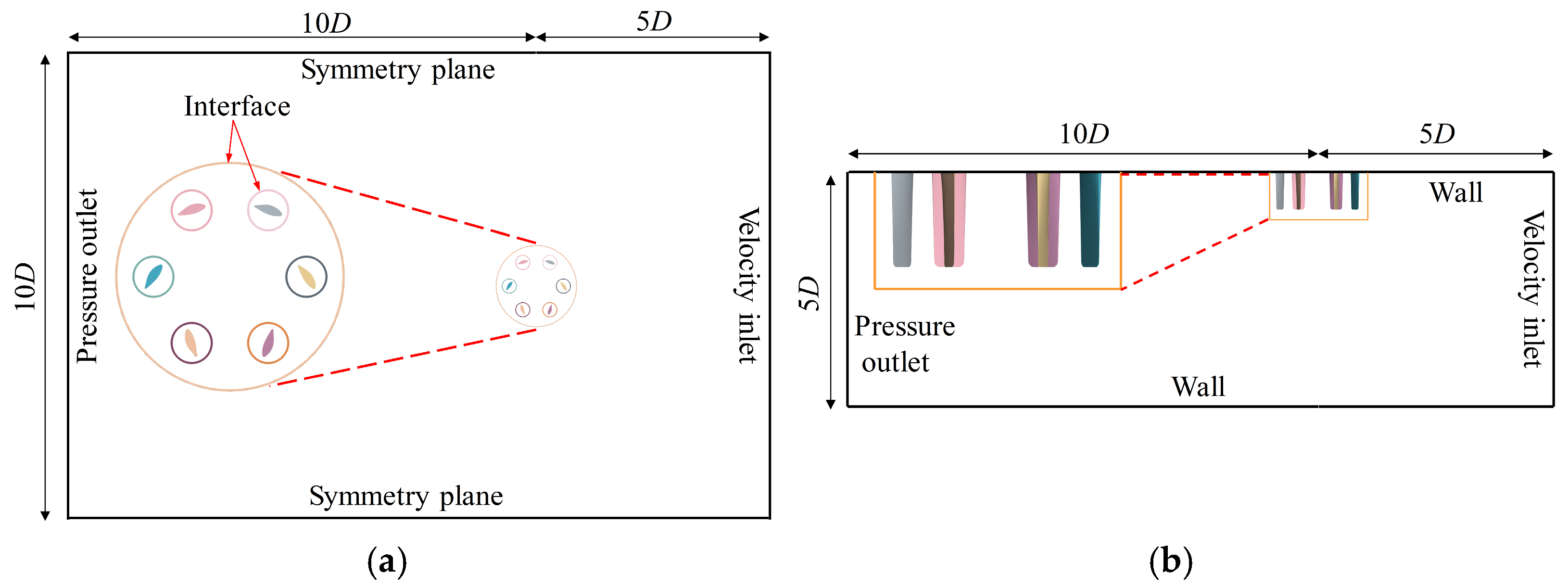
2.2. Numerical Simulation Methods

Over the past two decades, Computational Fluid Dynamics (CFD) methods based on viscous fluid mechanics have rapidly developed and have been progressively applied to the hydrodynamic assessment of Voith–Schneider Propellers (VSPs). This paper employs STAR-CCM+ 2022.1.1 software for CFD simulations, considering the fluid as viscous and incompressible, and solves the RANS equations using the SST k-ω model. The Report 2983 published by Ficken and Dickerson in 1969 is widely used for the validation of numerical models. Therefore, this study adopts the same six-blade VSP model as described in the report. The blades feature varying airfoil sections along the span and a slightly tapered rectangular section, with the self-rotation center located at the mid-chord point, as shown in Figure 4. Detailed parameters are listed in Table 1.
In this paper, the sliding mesh technique and UDF (User-Defined Function) control are employed to simulate the uniform revolution and variable-speed self-rotation motions of the VSP blades. As shown in Figure 5a, the entire computational domain is divided into the self-rotation domain, the revolution domain, and the stationary domain. Data exchange between these different domains is achieved by setting interfaces. To ensure fully developed flow within the computational domain, the propeller disk diameter D is used as the characteristic length. The length in the inflow direction is set to 5D, and the length in the outflow direction is set to 10D. The width and height of the computational domain are set to 10D and 5D, respectively. To simulate the real test environment where the VSP blades extend from the ship bottom, as shown in Figure 5b, the top surface of the blades is positioned flush with the top surface of the computational domain. The top and bottom surfaces of the computational domain are set as wall boundaries. The inflow boundary is set as a velocity inlet, the outflow boundary is set as a pressure outlet, and the side boundaries are set as symmetry planes.
Unstructured grids are used for meshing the computational domain, with a base size set to 3 mm. To ensure that the thickness of the first layer of wall-adjacent grid cells yields Y+ < 1, 10 layers of prism layers are applied on the blade surfaces, with a prism layer growth ratio set to 1.5. As shown in Figure 6a, the grids undergo gradual refinement starting from the far field. To improve the accuracy of simulating the internal flow field of the Voith–Schneider Propeller (VSP), the grid cell size within both the revolution domain and the self-rotation domain is set identically. Figure 6b shows the grid distribution in the self-rotation domain at different positions along the blade span direction.
The correction factor method is widely used in uncertainty analysis [18]. Following the ITTC guidelines, five grid sets were established for uncertainty verification, with a grid size growth rate of 2 . Analysis of the thrust coefficient calculation results across the different grid sets (Table 2) revealed that the medium grid exhibited the smallest error compared to the experimental value. Furthermore, the calculated thrust coefficient uncertainty values for all five grid sets were below 1% (Table 3). Therefore, considering both computational resources and calculation error, the medium grid was selected for subsequent computations.

3. Results

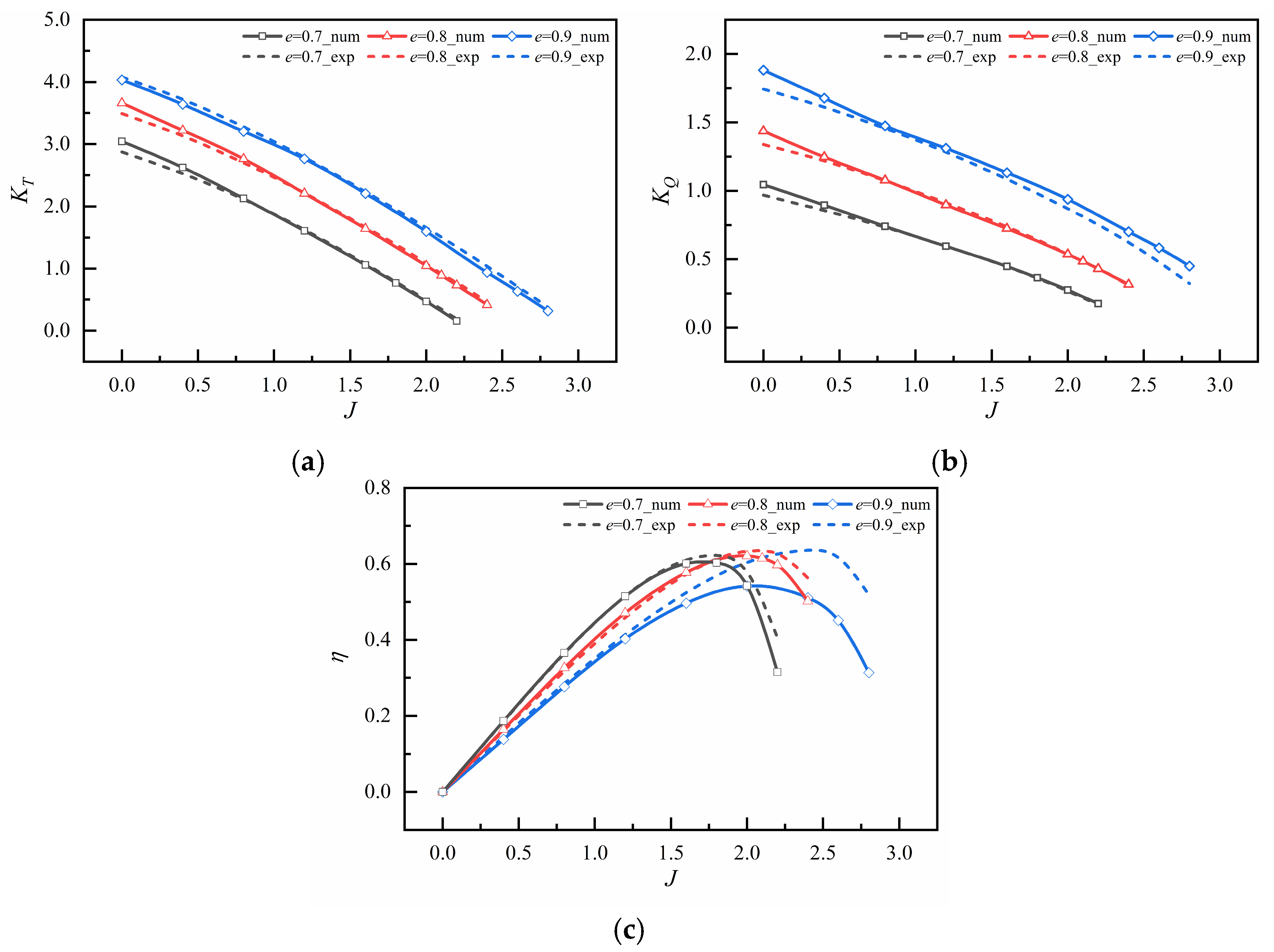
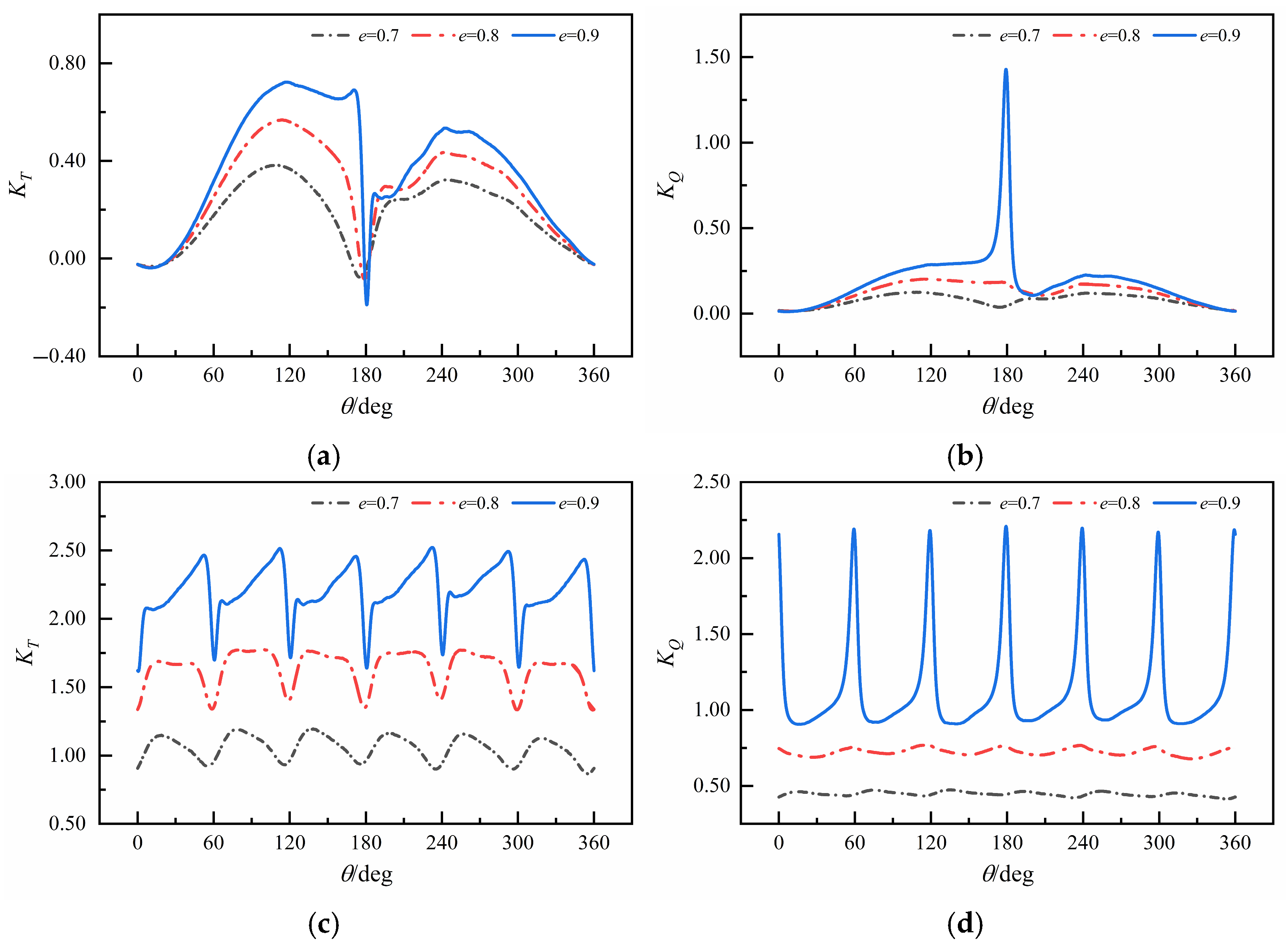
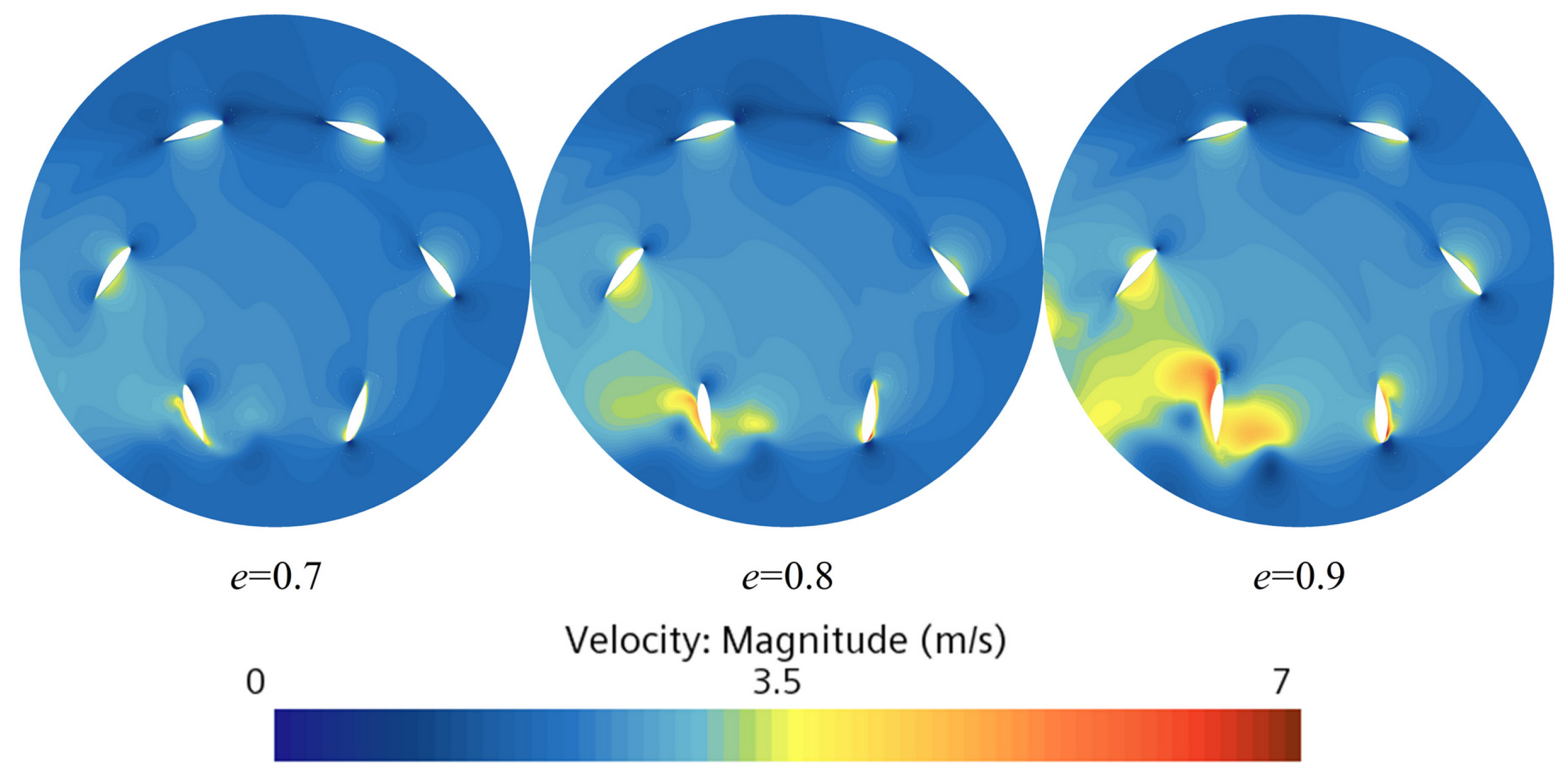
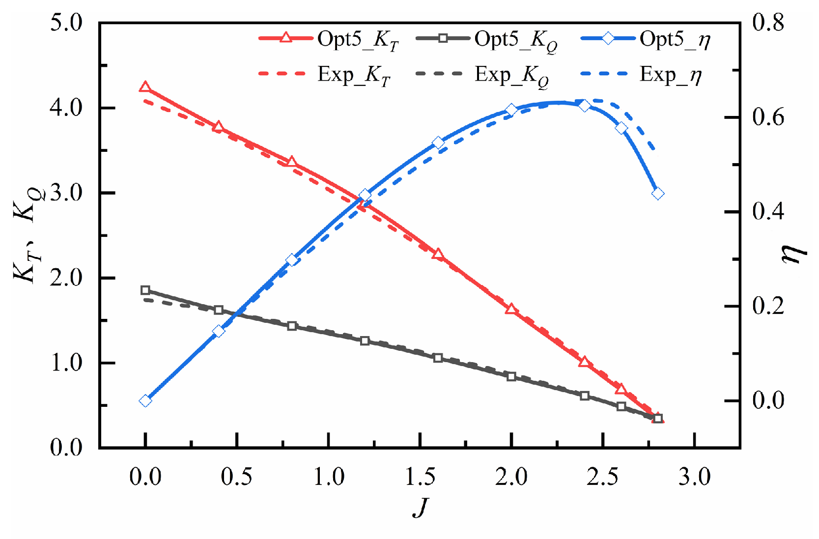
3.1. Open-Water Performance Analysis

The blades of the Voith–Schneider Propeller (VSP) undergo variable-speed self-rotation around their own axes while revolving uniformly with the propeller disk. The overall hydrodynamic force of the VSP is generated by the combined effect of all individual blades. As the eccentricity increases, the deflection angles and angular velocities during the blade self-rotation motion also increase significantly. This enhances the interaction with the water flow, resulting in a more complex hydrodynamic composition for the VSP. Therefore, it is imperative to conduct a detailed analysis of the hydrodynamic performance of the Voith–Schneider Propeller.
A comparison of the hydrodynamic calculation results with experimental results for the Voith–Schneider Propeller (VSP) under eccentricity conditions of 0.7, 0.8, and 0.9 is shown in Figure 7. It can be observed that both the thrust coefficient (KT) and torque coefficient (KQ) of the VSP increase with eccentricity but decrease with an increasing advance coefficient (J). Furthermore, under low and medium eccentricities (e = 0.7, e = 0.8), all hydrodynamic calculation results for the VSP agree well with the experimental data. However, at high eccentricity (e = 0.9), a significant discrepancy exists between the calculated efficiency and the experimental results.
Analysis indicates that the alteration in the Blade Steering Curve under high eccentricity may be the primary reason for this large error between the calculation and experiment. Nakonechny [19] mentioned in their report that the blade self-rotation angles were monitored during the tests. Figure 8 displays the measured blade motion trajectories of the VSP under eccentricity conditions of 0.7, 0.8, and 0.9. It can be seen that angle monitoring was performed every 15 degrees during the experiment. For the e = 0.7 and e = 0.8 conditions, the actual self-rotation angles of the VSP exhibit high coincidence with the theoretical curve. However, under the e = 0.9 condition, the VSP blades did not move according to the prescribed “normal intersection principle” when passing near the eccentric point. Limited by the executability of the cam control mechanism, multiple monitored self-rotation angle values deviated from the theoretical curve within the revolution angle range of 120 to 240 degrees. This may lead to changes in the hydrodynamic performance of the VSP, the specific effects of which will be explored in subsequent sections.
Studying the time-history of forces acting on VSP blades is crucial for revealing the underlying nonlinear and unsteady hydrodynamic characteristics. The theoretical angle of attack of the blade under different eccentricities is shown in Figure 9. It can be observed that the blade angle of attack increases with eccentricity. Furthermore, the angles of attack in the first half-cycle and the second half-cycle exhibit a symmetric distribution about the 180° revolution angle. While the blade thrust increases with the angle of attack, the actual angle of attack changes for blades in the second half-cycle as they pass through the wake generated by blades in the first half-cycle. Consequently, the hydrodynamic forces are asymmetric between the first and second half-cycles. Figure 10 shows the variation curves of hydrodynamic forces on a single blade and the overall propeller over one revolution cycle for the Voith–Schneider Propeller (VSP) at different eccentricities and an advance coefficient of J = 1.6. It can be observed that when the blades pass near the eccentric point, both the individual blade and the overall propeller exhibit strong unsteady pulsation phenomena. The characteristics of these unsteady forces become more pronounced with increasing eccentricity. Combining this with the laws of combined blade motion reveals that higher eccentricity leads to greater blade self-rotation angles and angular velocities at the same revolution angle position, resulting in larger thrust and torque generated by the blades. As shown in Figure 11, the flow field velocity near the eccentric point of the Voith–Schneider Propeller (VSP) increases with eccentricity. Consequently, the interaction between the blades and water flow intensifies, resulting in complex flow field variations. Due to the rapid flipping motion of the blades near the eccentric point—undergoing a time-history process of rapid acceleration and deceleration—the rate of change in the thrust and torque time-history curves of the blades accelerates significantly near the revolution angle of 180 degrees. This is particularly evident in the torque time-history curve of VSP blades under high eccentricity (e = 0.9), where the torque amplitude increases markedly due to the multiplied angular velocity amplitude. Furthermore, because of the phase difference between the motions of different blades, a rapid flipping motion occurs every 60 degrees. Consequently, the composite overall thrust and torque time-history curves exhibit significant periodic variations.

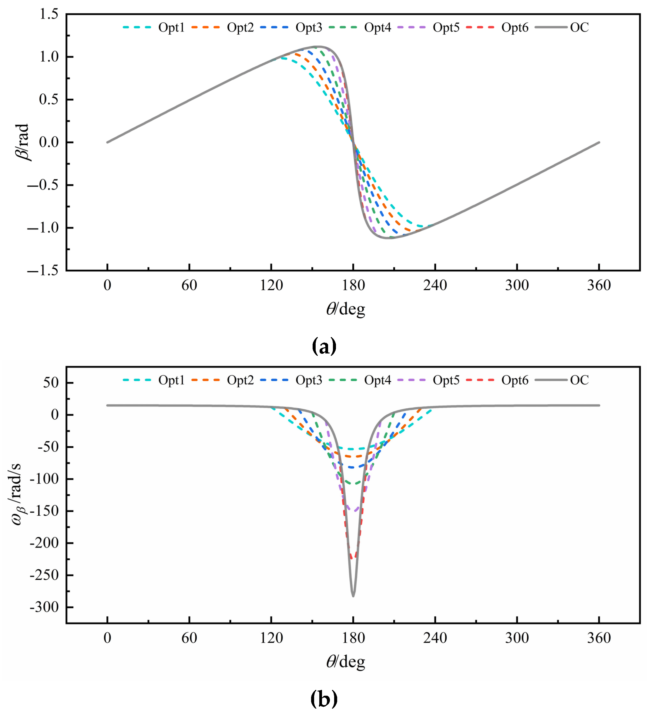
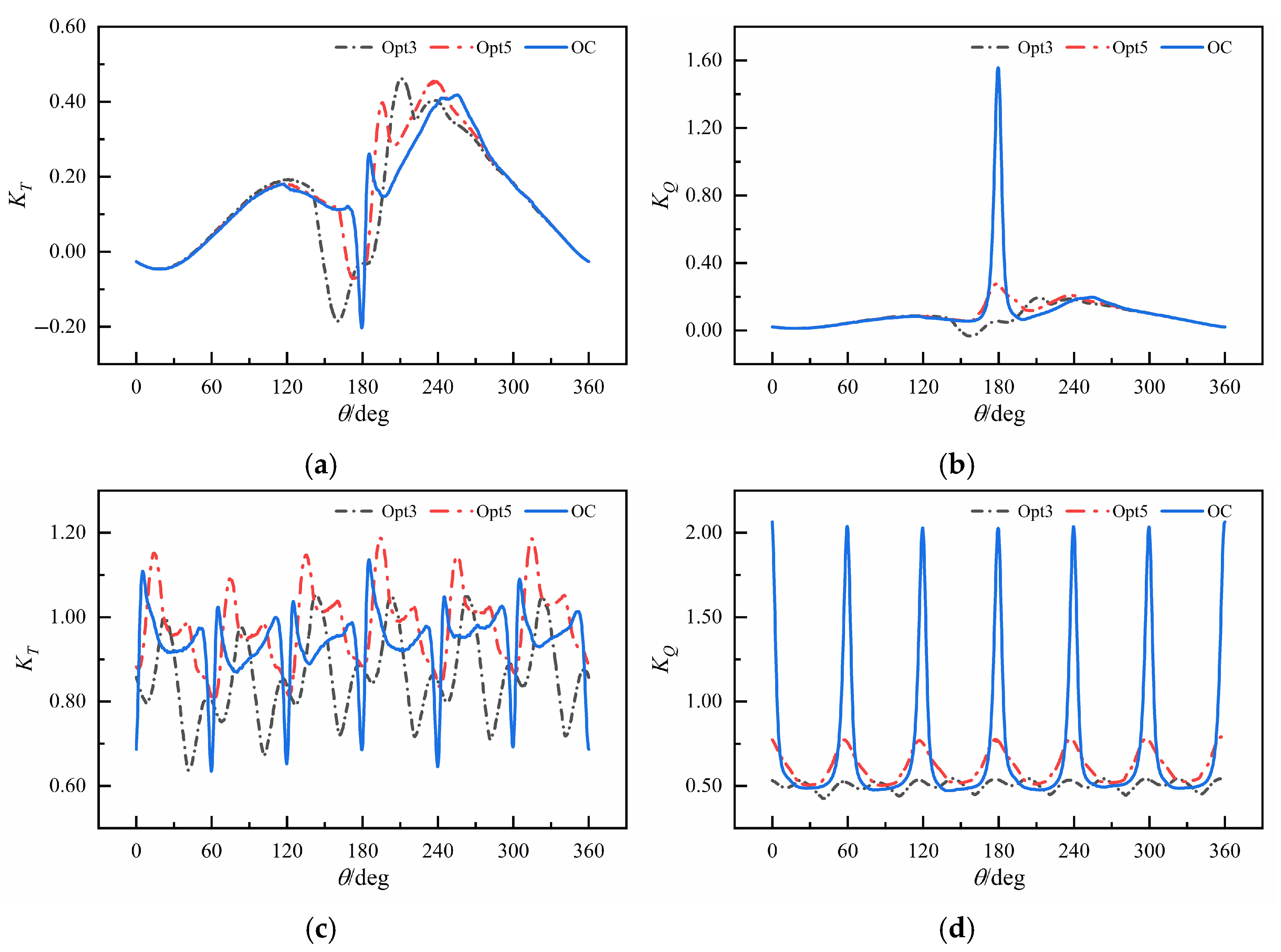
3.2. Investigation of Blade Steering Curve

Aiming at the strong unsteady hydrodynamic characteristics exhibited by VSP blades near the eccentric point due to rapid flipping under high eccentricity (e = 0.9), taking the reduction in self-rotation angles and angular velocities during the blade flipping process as the optimization strategy, the Blade Steering Curve is optimized via a parametric method to investigate its impact on the hydrodynamic performance of the Voith–Schneider Propeller.
The revolution angle range from 120 to 240 degrees was designated as the target optimization interval. Based on the original Blade Steering Curve (OC) adhering to the “normal intersection principle” under high eccentricity, with the self-rotation angles and angular velocities at the start and end positions of the interval serving as constraint conditions, a sinusoidal function was utilized for local fitting and replacement of the blade motion curve. The optimized equations for the blade self-rotation angle and angular velocity are given by Equations (10) and (11), respectively. By progressively narrowing the fitting interval to approximate the original curve, as shown in Figure 12, six sets of optimized Blade Steering Curves and their corresponding angular velocity curves were obtained using an optimization interval length of 20 degrees. Table 4 lists the specific parameters of the different optimized curves, including the fitting interval length, self-rotation angle amplitude, and self-rotation angular velocity amplitude. For Opt1–Opt4, the fitting intervals encompassed the revolution angle corresponding to the peak value of the original curve. The optimized curves exhibited reduced peak values due to the fitting equations, resulting in significant deviations from the original curve. In contrast, the fitting intervals for Opt5 and Opt6 did not include the revolution angle corresponding to the original curve’s peak value, yielding identical peak values in the optimized curves. Consequently, these optimized curves remained relatively close to the original curve.
β = a sin b ω t π ,
ω β = a b ω cos b ω t π ,
The hydrodynamic calculation results for the different optimized curves at the advance coefficient (J = 2.4) corresponding to the maximum efficiency point in the experiments are shown in Figure 13. It can be observed that changes in the Blade Steering Curve significantly impact the hydrodynamic performance of the Voith–Schneider Propeller (VSP). This is because the angles of attack exhibit significant differences among various optimized curves, as illustrated in Figure 14. The optimized torque coefficients (KQ) continuously increase as the fitting interval decreases. Both the thrust coefficient (KT) and efficiency exhibit a trend of first increasing and then decreasing with the reduction in the fitting interval. The maximum thrust occurs with the Opt5 curve, showing a 4.67% increase compared to the original curve (OC). The maximum efficiency occurs with the Opt3 curve, exhibiting a significant 27.08% increase compared to the OC. Since, at J = 2.4, the hydrodynamic performance of the Opt5 curve is close to the experimental value, and compared to the OC, it yields increased thrust while reducing torque by 12.74% and improving efficiency by 19.95%, this curve was selected for calculating the open-water performance curves across the full range of advance coefficients, as shown in Figure 15. It can be seen that the calculation error relative to the experimental results decreases, and the open-water performance curves exhibit better agreement. This further verifies that the blade motion during the experiment did not strictly adhere to the “normal intersection principle”.
To further investigate the impact of blade motion curves on the hydrodynamic performance of the Voith–Schneider Propeller (VSP), the Opt3 curve (corresponding to maximum efficiency), the Opt5 curve (corresponding to maximum thrust), and the original curve (OC) were selected to analyze the unsteady hydrodynamic characteristics of both individual blades and the overall VSP. Figure 16 shows the hydrodynamic time-history curves for blades and the overall VSP under these three blade motion curves. It can be observed that the unsteady pulsations of the optimized VSP are significantly improved. Based on the blade angle of attack distribution shown in Figure 13, it is observed that for blades employing the optimized curve, the thrust in the first half-cycle decreases as the angle of attack diminishes earlier. Furthermore, the rate of change in the angle of attack for the optimized curve slows down during the reversal process. Consequently, the rates of change for the optimized thrust coefficient and torque coefficient near 180° decrease. Compared to the OC curve, the Opt3 curve yields a 19.78% reduction in overall thrust pulsation and a 92.37% reduction in overall torque pulsation. Similarly, the Opt5 curve yields a 25.79% reduction in overall thrust pulsation and an 81.94% reduction in overall torque pulsation. Combining this with the optimized blade motion laws reveals that the Opt3 curve reduces the amplitude of both the self-rotation angle and angular velocity, weakening the interaction between the blades and the water flow. Consequently, the torque generated by the blades is substantially reduced, resulting in the highest calculated overall efficiency. The Opt5 curve maintains the same self-rotation angle amplitude as the original curve over the entire cycle. The key difference lies in reducing the self-rotation angle during the blade flipping process. After optimization, the thrust generated by the blades in the latter half of the cycle exceeds that of the original curve, leading to an increase in the overall thrust of the VSP.
Due to the rapid flipping of the blades near the eccentric point—which involves rapid changes in the peaks of the self-rotation angle and angular velocity—dynamic stall occurs under large angles of attack. This generates flow separation phenomena in the flow field within the revolution angle range of 180–240 degrees. The turbulence intensity is particularly strong under the original curve, as shown in Figure 17c. In contrast, the wake velocity distribution of the optimized VSP is more concentrated, and the intensity of the separation vortices is weakened, as shown in Figure 17a,b. This is beneficial for reducing the hydrodynamic pulsation of the Voith–Schneider Propeller.

4. Conclusions

To investigate the unsteady hydrodynamic characteristics of the Voith–Schneider Propeller (VSP) under high-eccentricity conditions, this study conducted open-water performance calculations and unsteady characteristic analysis for the VSP at low, medium, and high eccentricities. The research revealed the presence of strong unsteady pulsation phenomena near the eccentric point in the VSP. Experimental comparison indicated that the motion law of the blades might have changed under high eccentricity. Therefore, an optimization study on the motion law during the blade flipping process was carried out, specifically by generating different optimized Blade Steering Curves using a sinusoidal fitting strategy and investigating the impact of these optimized curves on the hydrodynamic performance of the VSP. The following conclusions were drawn:
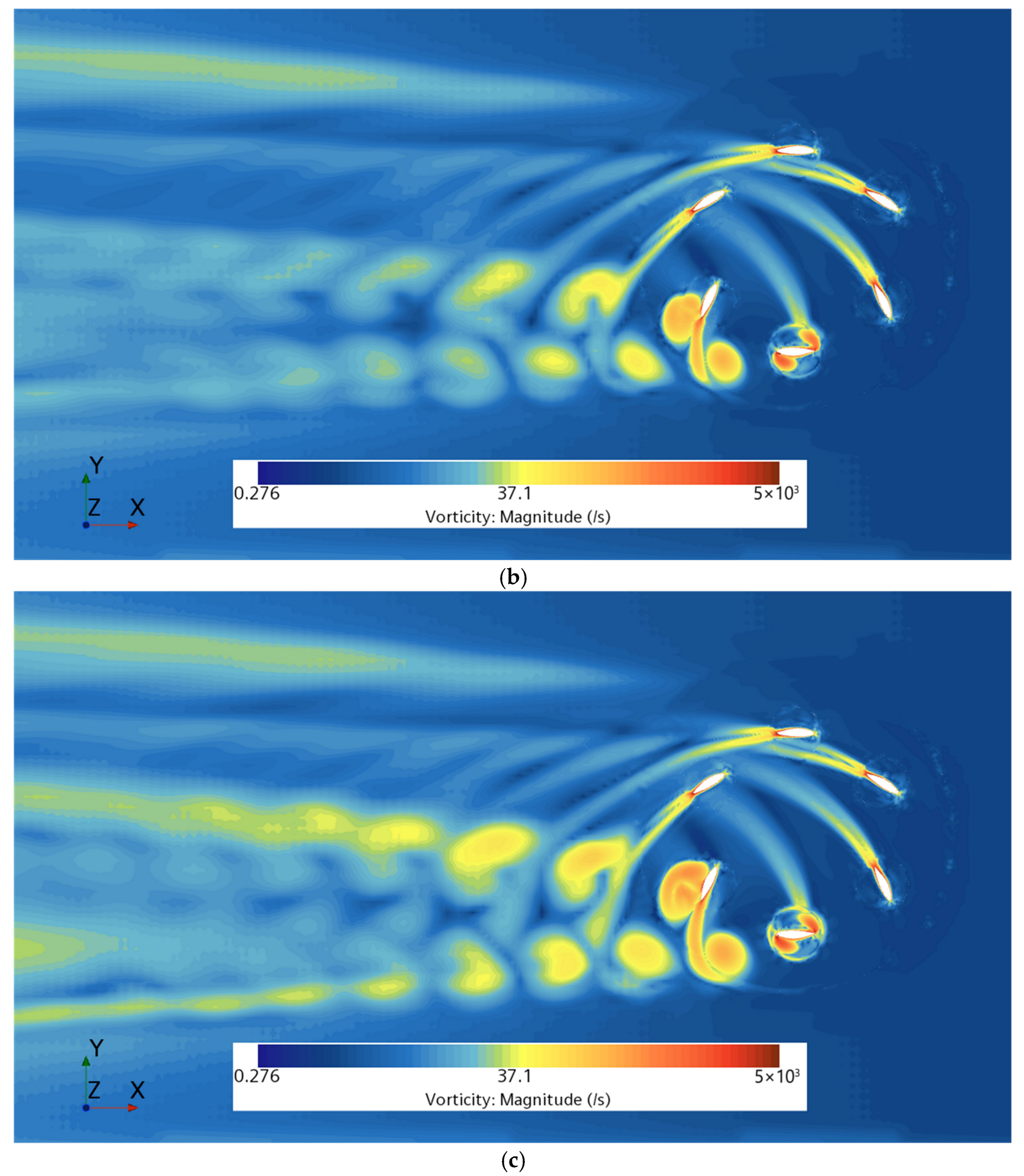
  • Under the high-eccentricity condition (e = 0.9), the amplitude of the blade self-rotation angular velocity of the VSP increases significantly. When blades pass near the eccentric point, strong unsteady hydrodynamic pulsation occurs, and the torque acting on the blades increases substantially, leading to a decrease in propulsion efficiency at high eccentricity.
  • Limited by the executability of the cam control mechanism, the VSP blades during rapid flipping in the experiment did not strictly adhere to the “normal intersection principle”. Therefore, in the design of high-performance VSPs, the amplitude of the blade self-rotation angular velocity should be constrained according to different control methods.
  • The appropriate design of the Blade Steering Curve can substantially improve the hydrodynamic performance. At J = 2.4, the Opt-5 curve generated via the sinusoidal fitting strategy enables a 25.19% reduction in overall thrust pulsation, an 81.94% reduction in overall torque pulsation, a 4.67% increase in thrust, a 12.74% reduction in torque, and a 19.95% improvement in efficiency for the VSP.

Author Contributions

Conceptualization, Z.L. and W.X.; methodology, W.X.; software, W.X.; validation, W.X., W.L. and Q.C.; formal analysis, W.X.; investigation, W.L.; resources, Z.L.; data curation, W.X.; writing—original draft preparation, W.X.; writing—review and editing, Z.L.; visualization, W.L.; supervision, Q.C.; project administration, Z.L.; funding acquisition, Z.L. All authors have read and agreed to the published version of the manuscript.

Funding

This research was funded by the National Natural Science Foundation of China, grant number 52371343.

Data Availability Statement

The original contributions presented in this study are included in the article. Further inquiries can be directed to the corresponding author.

Conflicts of Interest

The authors declare no conflicts of interest.

References

  1. Liu, S.; Huang, H.; Leng, J.; Chen, L.; Huang, J. The Design and Application of a New Vertical-Axis Ship Propeller. In Proceedings of the OCEANS 2015-MTS/IEEE Washington, Washington, DC, USA, 19–22 October 2015; IEEE: Washington, DC, USA, 2015; pp. 1–4. [Google Scholar]
  2. Desai, M.; Gokhale, R.; Halder, A.; Benedict, M.; Young, Y.L. Augmenting Maneuverability of UUVs with Cycloidal Propellers. Young 2020, 1, 3. [Google Scholar]
  3. Sarchin, T.H.; Tryner, H.G. Cycloidal Propulsion and Control for Ship Handling Tugs. Nav. Eng. J. 1970, 82, 52–69. [Google Scholar] [CrossRef]
  4. Taniguchi, K. Sea Trial Analysis of the Vertical Axis Propellers. In Fourth Symposium on Naval Hydrodynamics: Propulsion Hydroelasticity; Office of Naval Research and Web Institute of Naval Architecture: Washington, DC, USA, 1962; pp. 27–31. [Google Scholar]
  5. Haberman, W.L.; Harley, E.E. Performance of Vertical Axis (Cycloidal) Propellers Calculated by Taniguchi’s Method. In Hydromechanics Laboratory Research and Development Report 1564; Report No. SR0090101; David Taylor Model Basin: Washington, DC, USA, 1961. [Google Scholar]
  6. Zhu, D.M. A Computational Method for Cycloidal Propellers. Int. Shipbuild. Prog. 1981, 28, 102–111. [Google Scholar] [CrossRef]
  7. Ficken, N.L.; Dickerson, M.C. Experimental Performance and Steering Characteristics of Cycloidal Propellers; Defense Technical Information Center: Fort Belvoir, VA, USA, 1969. [Google Scholar]
  8. Bartels, J.; Jürgens, D. Latest Developments in Voith Schneider Propulsion Systems. In Proceedings of the 18th International Tug & Salvage Convention, Miami, FL, USA, 26–29 April 2004. [Google Scholar]
  9. Bartels, J.-E.; Jürgens, D. The Voith Schneider Propeller: Current Applications and New Developments; Voith Turbo Marine GmbH: Heidenheim, Germany, 2006. [Google Scholar]
  10. Bakhtiari, M.; Ghassemi, H.; Sakaki, A.; He, G. Optimisation Scheme Applied to the Voith-Schneider Propulsion System Using Genetic Algorithm. Ships Offshore Struct. 2021, 16, 650–658. [Google Scholar] [CrossRef]
  11. Li, T.; Hu, J.; Wang, Y.; Zhang, W.; Mao, Y.; Guo, C. Hydrodynamic Analysis of Cycloidal Propellers. Ships Offshore Struct. 2022, 17, 2116–2129. [Google Scholar] [CrossRef]
  12. Sun, Z.; Li, H.; Liu, Z.; Wang, W.; Zhang, G.; Zong, Z.; Jiang, Y. Study on Hydrodynamic Performance of Cycloidal Propeller with Flap at the Trailing Edge. Ocean. Eng. 2021, 237, 109657. [Google Scholar] [CrossRef]
  13. Hu, J.; Yan, Q.; Sun, S.; Li, F.; Ma, J. Numerical Simulation to Assess Hydrodynamic Performance of Cycloidal Propellers during Maneuvering. Ocean. Eng. 2023, 273, 113931. [Google Scholar] [CrossRef]
  14. Liu, Z.; Sun, Z.; Zhang, G.; Sun, Y. Study on Thrust Directional Steadiness of Cycloidal Propeller. Ocean. Eng. 2023, 287, 115840. [Google Scholar] [CrossRef]
  15. Liu, W.; Liu, Z.; Chen, Q.; Ma, C. Research on Efficiency Optimization of the Voith-Schneider Propeller Based on Motion Curve Parameter Control. Ocean. Eng. 2024, 299, 117136. [Google Scholar] [CrossRef]
  16. Jürgens, B.; Fork, W. The Fascination of the Voith-Schneider Propeller: History and Engineering; Koehlers Verlagsgesellschaft mbH: Minden, Germany, 2002; ISBN 3-7822-0859-5. [Google Scholar]
  17. Jürgens, D.; Palm, M.; Singer, S.; Urban, K. Numerical Optimization of the Voith-Schneider® Propeller. Z Angew. Math. Mech. 2007, 87, 698–710. [Google Scholar] [CrossRef]
  18. Zhai, S.; Jin, S.; Chen, J.; Liu, Z.; Song, X. CFD-Based Multi-Objective Optimization of the Duct for a Rim-Driven Thruster. Ocean. Eng. 2022, 264, 112467. [Google Scholar] [CrossRef]
  19. Nakonechny, B.V. Design of a 9-Inch Cycloidal Propeller Model Unit and Some Experimental Results; No. NSRDC-3150. 1974. Available online: https://apps.dtic.mil/sti/citations/ADA005768 (accessed on 21 July 2025).
Figure 1. Schematic of VSP blade motion (e = 0.9).
Jmse 13 01407 g001
Figure 2. Self-rotation angle and angular velocity of the VSP blades under different eccentricities: (a) β and (b) ω β .
Jmse 13 01407 g002
Figure 3. Schematic of VSP blade velocity and force (e = 0.9).
Jmse 13 01407 g003
Figure 4. VSP model for CFD.
Jmse 13 01407 g004
Figure 5. Division of the computational domain: (a) top view and (b) side view.
Jmse 13 01407 g005
Figure 6. Reference grid: (a) computational domain and (b) self-rotation domain.
Jmse 13 01407 g006aJmse 13 01407 g006b
Figure 7. Hydrodynamic coefficient curves under different advance coefficients: (a) KT, (b) KQ, and (c) η.
Jmse 13 01407 g007
Figure 8. Measured blade self-rotation angle: (a) e = 0.7, (b) e = 0.8, and (c) e = 0.9.
Jmse 13 01407 g008
Figure 9. Variation in blade angle of attack under different eccentricities (J = 1.6).
Jmse 13 01407 g009
Figure 10. Variation in the hydrodynamics of the VSP with the revolution angle (J = 1.6): (a) KT of single blade, (b) KQ of single blade, (c) KT of propeller, and (d) KQ of propeller.
Jmse 13 01407 g010
Figure 11. Velocity field distributions under different eccentricities (J = 1.6).
Jmse 13 01407 g011
Figure 12. Self-rotation angle and angular velocity of the VSP blades under different Blade Steering Curves: (a) β and (b)   ω β .
Jmse 13 01407 g012
Figure 13. Optimized results of VSP (J = 2.4).
Jmse 13 01407 g013
Figure 14. Variation in blade angle of attack under different Blade Steering Curves (J = 2.4).
Jmse 13 01407 g014
Figure 15. Hydrodynamic curves of Opt5.
Jmse 13 01407 g015
Figure 16. Variation in the hydrodynamics optimization results of the VSP with the revolution angle (J = 2.4): (a) KT of single blade, (b) KQ of single blade, (c) KT of propeller, and (d) KQ of propeller.
Jmse 13 01407 g016
Figure 17. Vorticity distribution under different Blade Steering Curves (J = 2.4): (a) Opt3, (b) Opt5, and (c) OC.
Jmse 13 01407 g017aJmse 13 01407 g017b
Table 1. VSP model parameters.
ParameterSymbolValueUnit
DiameterD22.86cm
Avg. Chord c avg 4.026cm
Max. Chord c max 4.328cm
LengthL11.43cm
Revolution speedn5rps
Table 2. Thrust coefficients under different grid numbers (e = 0.7, J = 1.8).
MeshMesh Size (mm)Mesh Count (M)KTExpError (%)
1—Very fine1.414.30.7910.7870.508
2—Fine1.710.00.7900.7870.381
3—Medium2.07.50.7880.7870.127
4—Coarse2.45.40.7830.787−0.508
5—Very coarse2.84.20.7740.787−1.652
Table 3. Grid uncertainty analysis (e = 0.7, J = 1.8).
MeshRGPGCGUG%S
1–2–30.5002.0011.0010.127%
2–3–40.4002.6451.5010.339%
3–4–50.5551.6970.8000.798%
Table 4. Parameters of optimized Blade Steering Curves.
BSCFitting Interval (deg)Max Angle (rad)Max Angular Velocity (rad/s)
Opt1120–2400.9834−53.2870
Opt2130–2301.0374−65.0843
Opt3140–2201.0842−81.8950
Opt4150–2101.1156−107.5383
Opt5160–2001.1198−150.4127
Opt6170–1901.1198−226.9734
OC1.1198−282.7433
Disclaimer/Publisher’s Note: The statements, opinions and data contained in all publications are solely those of the individual author(s) and contributor(s) and not of MDPI and/or the editor(s). MDPI and/or the editor(s) disclaim responsibility for any injury to people or property resulting from any ideas, methods, instructions or products referred to in the content.

