Article

Novel Polarization Construction Method and Synchronization Algorithm for Underwater Acoustic Channel Under T-Distribution Noise Environment

1
Institute of Logistics Science and Engineering, Shanghai Maritime University, Shanghai 201306, China
2
Merchant Marine College, Shanghai Maritime University, Shanghai 201306, China
3
Navigation College, Jimei University, Xiamen 361021, China
4
School of Computer Information and Engineering, Changzhou Institute of Technology, Changzhou 213032, China
5
Shanghai Ship and Shipping Research Institute Co., Ltd., Shanghai 200135, China
*
Authors to whom correspondence should be addressed.
J. Mar. Sci. Eng. 2025, 13(2), 362; https://doi.org/10.3390/jmse13020362
Submission received: 21 January 2025 / Revised: 2 February 2025 / Accepted: 12 February 2025 / Published: 15 February 2025
(This article belongs to the Section Physical Oceanography)

Abstract

:
Underwater acoustic channel (UWAC) is characterized by significant multipath effects, strong time-varying properties and complex noise environments, which make achieving high-rate and reliable underwater communication a formidable task. To address the above adverse challenges, this study first presents a novel, robust and efficient polar code construction (NREPCC) method using the base-adversarial polarization weight (BPW) algorithm tailored for typical ocean channel models, including invariable sound velocity gradient (ISVG) channels, negative sound velocity gradient (NSVG) channels, and positive sound velocity gradient (PSVG) channels. Subsequently, a robust and reliable polar-coded UWAC system model based on the orthogonal frequency division multiplexing (OFDM) technique is designed using the t -distribution noise model in conjunction with real sea noise data fitting. Then, an enhanced time synchronization and packet detection algorithm based on t -distribution is proposed for the performance optimization of the polar-coded UWAC OFDM system. Finally, extensive numerical simulation results confirm the excellent performance of the proposed NREPCC method and polar-coded UWAC OFDM system under a variety of channel conditions. Specifically, the NREPCC method outperforms low-density parity-check (LDPC) codes by approximately 0.5~1 dB in PSVG and ISVG channels while maintaining lower encoding and decoding complexity. Moreover, the robustness of the NREPCC method under t -distribution noise with varying degrees of freedom is rigorously validated, which renders vital technical support for the design of high-precision and high-robustness UWAC systems.

1. Introduction

With the advancement of underwater acoustic (UWA) communication technology and ocean sensor technology, as well as the leapfrog development of ocean observation equipment, countries around the world have been accelerating their pace of ocean space exploration and resource exploitation. To achieve efficient and robust monitoring of all elements of the ocean environment, as well as to enhance the ability to respond to unexpected marine events, the key lies in strengthening the ability of real-time and high-speed transmission of sensory data by underwater acoustic Internet of things (IoT). Consequently, designing high-precision and high-robustness hydroacoustic communication systems with high generalizability has become a research hotspot in the field of ocean communication [1,2,3,4]. Specifically, the UWA channel faces a series of problems, such as random variations in spatial/temporal/frequency parameters, strong multipath effects, fast fading, limited bandwidth, and complex noise interference, which can lead to suboptimal communication quality and elevated propagation delay [5,6,7]. Therefore, achieving real-time, high-speed underwater acoustic communication (UWAC) remains a critical dilemma in the field of hydroacoustic signal processing [8]. Figure 1 illustrates the schematic diagram of the underwater acoustic communication wireless sensor networks for tasks such as continuous monitoring of the ocean.
In recent years, the UWA orthogonal frequency division multiplexing (OFDM) communication systems have attracted extensive attention from many scholars due to their high bandwidth utilization, strong anti-multipath and inter-symbol interference capabilities, simplified receiver channel equalization and seamless compatibility with advanced signal processing technologies and have become the focus of research on high-speed UWAC systems [9,10,11]. To enhance the transmission quality of UWA communication and satisfy the requirements of specific underwater mission scenarios, such as underwater voice communication with a bit error rate (BER) of less than 10 3 , numerous scholars have initiated research on UWA OFDM communication through the integration of diverse techniques, including channel coding, time–frequency synchronization, channel estimation and equalization, Doppler frequency shift estimation and compensation [12,13,14]. Among these, the channel coding technique increases redundancy by adding checksum bits to the transmitted data, thereby enabling the receiver to detect and, in some cases, correct errors caused by noise and interference during transmission. Over the past two decades, a variety of channel coding methods, including convolutional codes [15,16], turbo codes [17] and LDPC codes [18], have been successfully employed in communication systems, demonstrating excellent performance. Nevertheless, the high complexity of the above three coding techniques remains a dominant obstacle to the low-power, low-latency and robust implementation of UWAC under real multi-constraint conditions, such as restricted decoding latency and high spectral efficiency. With the advent of the oceanic big data era, we urgently need novel approaches to simplify the design, construction, storage and decoder implementation of channel coding. Polar codes [19] are a recently propounded coding method that has attracted extensive research interest due to its potential to approximate the Shannon limit. Compared to turbo codes and LDPC codes, polar codes possess a more direct coding structure and lower decoding complexity while maintaining the same code length and code rate [20]. However, the performance of polar codes is contingent upon the specific channel conditions, and the polarization construction method employed in polar codes directly influences their performance, which, in turn, restricts the applicability of polar codes in the domain of UWAC [21,22]. Therefore, one of the main objectives of this work is to present a low-complexity and robust polar code construction method for a UWAC OFDM system.
In addition, the prevalent non-Gaussian noise characteristics in the underwater environment [23,24] lead to the degradation of polar code performance, which hinders the application of polar codes in UWAC. In previous studies on UWAC, most of the channel decoding strategies were designed based on Gaussian noise models. However, the actual underwater noise environment tends to exhibit heavy-tailed and impulsive behaviors, which is more consistent with t -distributed noise. Hence, in our work, the t -distributed noise is employed to truly reflect the fading and fluctuation of UWA signal propagation.
In this context, with the comprehensive consideration of the complexity and time-varying nature of the UWA channel, this paper first proposes a new polar code construction method applicable to different UWA channel conditions. Secondly, considering the non-Gaussian and non-linear characteristics of UWA noise, the fitting simulation is carried out by using the relevant sea data, and the results show that the UWA noise complies with t -distribution. Meanwhile, we design a robust and efficient polar-coded UWAC OFDM system model. Further, an enhanced time synchronization and packet detection algorithm based on t -distribution is presented for the performance optimization of UWAC in a non-Gaussian noise environment. Finally, extensive numerical simulation results demonstrate the effectiveness and superiority of the proposed method in UWA-like communication scenarios. The main contributions and innovations of our work can be summarized as follows:
(1)
Aiming at the multipath and time-varying characteristics, we present a novel, robust and efficient polar code construction method using the base-adversarial polarization weight (BPW) algorithm, named the NREPCC method, for the UWAC channel. Meanwhile, to subsequently validate the NREPCC method, we built the polar-coded UWAC OFDM system model.
(2)
Combined with a more realistic t-distribution noise model, an improved synchronization algorithm is proposed for packet detection, which effectively enhances the communication efficiency and stability of the polar-coded UWAC OFDM system.
(3)
We thoroughly validate and comprehensively assess the performance of the proposed polar construction method and the polar-coded UWAC OFDM scheme with detailed theoretical analysis and numerical simulation experiments.
The remainder of this work is organized as follows. Section 2 presents the related work on UWA channel coding, while in Section 3, the fundamental theories of the polar codes are illustrated. In Section 4, we show the UWA channel model and present the novel polar code construction method, while the polar-coded UWAC OFDM system model and improved time synchronization algorithm are developed in Section 5. The validation and analysis of the simulation results and findings with benchmark methods in three classical UWA channels are presented in Section 6, and finally, the concluding remarks and future directions are given in Section 7.

2. Related Work

The UWA OFDM technique has become a sought-after research direction in the field of UWAC due to its advantages such as high spectrum utilization and high resistance to inter-code interference. However, the complex underwater acoustic propagation environment, such as variable sound speed profile (SSP) and severe multipath effect, poses a great challenge for the design of an efficient and reliable UWAC system.
In this section, we review the related works on UWA OFDM communication systems and polar code construction methods. To ensure a comprehensive and focused review, we have established the following inclusion and exclusion criteria:
  • Inclusion criteria:
    (1)
    Studies focusing on UWA OFDM communication systems, particularly those addressing multipath effects and time-varying channel characteristics.
    (2)
    Research on polar code construction methods, especially those tailored for non-Gaussian noise environments.
    (3)
    Works published in high-quality journals or conferences within the last five years.
  • Exclusion criteria:
    (1)
    Studies that do not directly address UWA OFDM communication or polar code construction.
    (2)
    Research that lacks experimental validation or relies solely on theoretical analysis without practical application.
    (3)
    Works published in non-peer-reviewed venues or those with limited relevance to our research objectives.
Based on these criteria, we organize the related works into two main categories: (1) polar code construction method and (2) noise modeling in underwater environments.
In the UWA OFDM communication system, achieving efficient, accurate and robust transmission of underwater information from the sensing node to the receiving node has been a long-standing hot concern of researchers, among which channel coding is one of the feasible and effective technical means. Therefore, in the UWAC system, it is imperative to develop efficient, robust and low-complexity channel-coding algorithms. The emergence of polar codes offers a high potential breakthrough orientation for high-speed and reliable communication in UWA OFDM communication systems. In practical applications of polar codes, it is essential to construct the index set of polarized subchannels to allocate information bits and frozen redundancy bits prior to coding, and this process is referred to as polar code construction [19]. According to different types and characteristics of channels, certain efforts have been conducted, and some effective construction methods have been proposed in recent years. For binary erasure channels, Arikan [19] proposed the Bhattacharyya parameter method, which iteratively and recursively determines the upper bound of the error probabilities for polarized subchannels with linear complexity. For any binary discrete memoryless channel, the complexity of the Bhattacharyya parameter method increases exponentially with the code length and becomes impractical. Subsequently, Mori and Tanaka presented the density evolution method with linear complexity in the block length for arbitrary symmetric binary-input memoryless channels [25]. To further reduce computational complexity, Tal and Vardy extended the density evolution method through quantization and solved for the lower and upper bounds of the error probability under a given maximum quantization level [26]. Trifonov [27] effectively reduced the computational complexity by using Gaussian approximation in the density evolution. In fading channels, various techniques have been utilized, including the Gaussian approximation [28] based on mutual information equivalence and the minimum entropy gap principle, the Monte Carlo approximation method [19] and the Design-SNR approach [29].
Despite the success of polar codes in terrestrial wireless communication, their application in UWAC still faces several difficulties. As the only physical medium capable of transmitting long-distance information underwater, the UWA channel is much more complex than the radio channel. The statistical properties of the UWA channel display random spatiotemporal variability characteristics with time-varying multipath effects, non-uniform Doppler frequency shifts and Doppler spreading, which makes most of the existing polar code construction methods lack better generalization and robustness and, thus, cannot be customized for a specific UWA channel [30]. To this end, Xing and Chen et al. [21,31] carried out simulation performance analysis and UWA experimental studies on polar codes constructed using the Monte Carlo method. Subsequently, Zhai et al. [32] further proposed a Monte Carlo-based polar code construction algorithm tailored for the UWA channel in coded modulation scenarios. Although Zhai et al.’s strategy enables reliable subchannel selection within 200 transmissions using the Monte Carlo method, it still has certain limitations due to the complexity/variability of underwater environments and the power constraints of ocean equipment.
In addition, in UWA communications, the design and performance evaluation of most polar codes assume that the ocean ambient noise obeys a Gaussian distribution, ignoring the effect of non-Gaussian and non-linear noise. It has been demonstrated that underwater ambient noise does not follow the traditional Gaussian noise distribution [23,33] and that the noise characteristics are determined by a probability density function with wide tails and impulse behavior [34]. The Gaussian mixture model proposed by Banerjee and Agrawal [35] is a widely used non-Gaussian model with generic approximation properties. Li et al. [36] verified that the Gaussian mixture model can effectively estimate the ocean noise probability density function. In shallow underwater environments especially, the ambient noise distribution dominated by krill follows a symmetric α-stable distribution [37]. In addition, the t -distribution has received much attention for its wider tail property compared to the Gaussian distribution. Therefore, considering such non-Gaussian noise models within the framework of polar codes to enhance the robustness and reliability of the system is still one of the focuses of current research. Meanwhile, an effective time synchronization strategy is crucial to ensure the integrity of ocean data and the efficiency of UWAC systems. Existing synchronization algorithms are predominantly developed for multipath fading channels under Gaussian noise conditions and lack experimental validation in highly variable and complex underwater environments [38]. Consequently, there is an urgent necessity to propose time synchronization algorithms that can adapt to more complex noise distributions, such as t -distribution noise [39], which requires synchronization algorithms that are not only able to accurately estimate the time delay but also able to deal with outliers in ocean noise.

3. Polar Codes

This section provides an overview of the fundamental principles and techniques related to polar codes, which are essential for understanding their application in underwater acoustic communication (UWAC) systems. The main goal of this section is to introduce the concept of channel polarization, explain the encoding and decoding processes of polar codes, and lay the theoretical foundation for the subsequent chapters.

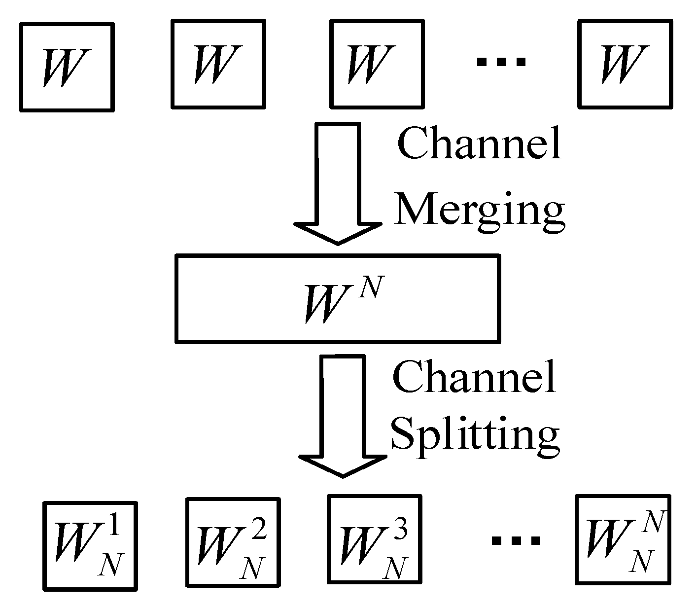
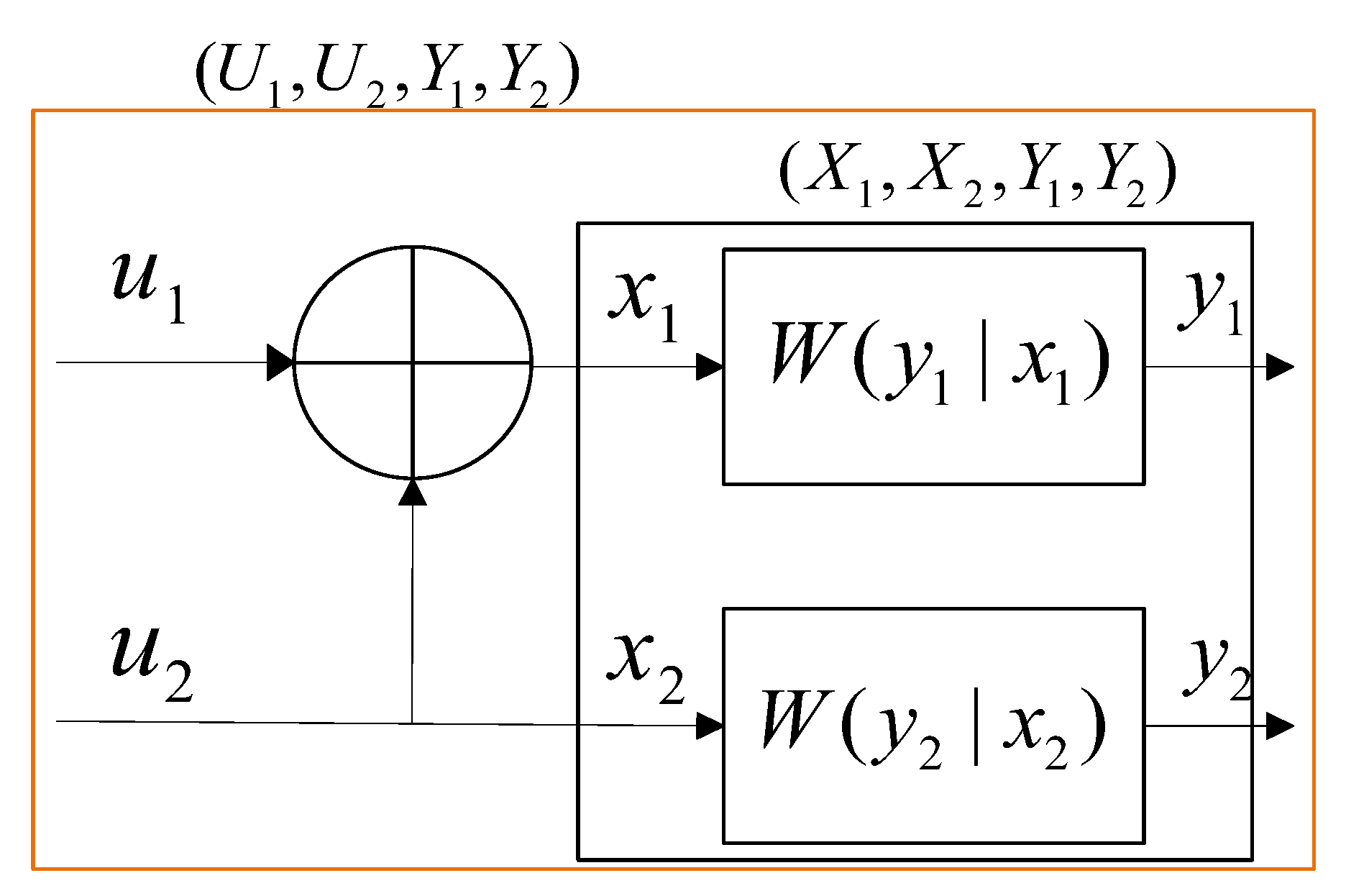
3.1. Channel Polarization Principle

Polar codes are the first coding scheme for which it has been theoretically demonstrated that the channel capacity can attain the Shannon limit [19], with their fundamental principle based on channel polarization. In the context of a binary discrete memoryless channel (B-DMC), let the input symbol set be X and the output symbol set be Y . The transition probability of the channel is denoted as W ( y | x ) , which represents the probability of receiving output Y given the input X . The characteristics of the channel are typically described using mutual information I ( W ) and the Bhattacharyya parameter Z ( W ) . The mutual information I ( W ) quantifies the information transmission capability of the channel and, in the case of a symmetric channel, it is equivalent to the channel capacity, which defines the maximum error-free transmission rate. On the other hand, the Bhattacharyya parameter Z ( W ) measures the reliability of the channel, where a lower value indicates a lower probability of transmission errors. These two parameters generally exhibit an inverse relationship, meaning that as mutual information increases, the Bhattacharyya parameter decreases, indicating improved transmission performance, and vice versa. Their mathematical expressions are given as follows:
I ( W ) 1 2 y Y x X W ( y | x ) log 2 2 W ( y | x ) W ( y | 0 ) + W ( y | 1 )
Z ( W ) y Y W ( y | 1 ) W ( y | 0 )
Polar codes utilize channel polarization, a process that transforms a channel into multiple subchannels with varying reliability. Some subchannels become highly reliable, while others deteriorate into unreliable ones. This transformation enables the design of a coding scheme that approaches Shannon capacity, ensuring both efficient and reliable communication. As shown in Figure 2, channel polarization occurs through two key steps: combining and splitting. Initially, multiple independent and identically distributed binary symmetric channels are combined into a single channel. This combined channel is then decomposed into multiple subchannels through specific transformations. As a result, the subchannels’ performance diverges—some become nearly noiseless, capable of transmitting information with minimal errors, while others degrade into completely noisy channels that are essentially unusable for reliable communication.
Figure 3 shows the fundamental unit of a polar code with a code length of N = 2 , where ⊕ denotes modulo-2 addition and encompasses two equivalent probability distributions: ( U 1 , U 2 , Y 1 , Y 2 ) and ( X 1 , X 2 , Y 1 , Y 2 ) , where ( U 1 , U 2 ) represents the source sequence, ( Y 1 , Y 2 ) denotes the received signal sequence, ( x 1 , x 2 ) = ( u 1 , u 2 ) 1 0 1 1 = ( u 1 u 2 , u 2 ) corresponds to the codeword bits associated with ( u 1 , u 2 ) , and F = 1 0 1 1 is the generator matrix of the polar code with a code length N = 2 . The two channels W ( y 1 | x 1 ) and W ( y 1 | x 1 ) represent two successive uses of the channel W used to transmit x 1 and x 2 , respectively. ( u 1 , u 2 ) corresponds one-to-one with ( x 1 , x 2 ) , and the mutual information of u 1 and u 2 after passing through the channel W can be expressed as follows:
I ( Y 1 Y 2 ; U 1 ) + I ( Y 1 Y 2 U 1 ; U 2 ) = 2 I ( X 1 ; Y 1 ) = 2 I ( W )
The above equation demonstrates that the information transmitted through two uses of the channel W is equal to the sum of the information that can be transmitted by the polarized subchannels and that the polarization process does not reduce the channel’s overall information transmission capability. The following assumes that the source bits U 1 and U 2 are independent and identically distributed Bernoulli (1/2) random variables:
2 I ( X 1 , Y 1 ) = ( a ) I ( X 1 , X 2 ; Y 1 , Y 2 ) = ( b ) I ( U 1 , U 2 ; Y 1 , Y 2 ) = ( c ) I ( U 1 ; Y 1 , Y 2 ) + I ( U 2 ; Y 1 , Y 2 | U 1 ) = ( d ) I ( U 1 ; Y 1 , Y 2 ) + I ( U 2 ; Y 1 , Y 2 , U 1 )
where the equal sign (a) denotes the chain rule for chain information, and the equal sign (b) signifies X U . Given the premise of I ( U 2 ; Y 1 U 1 | Y 2 ) 0 , it follows that I ( Y 1 Y 2 U 1 ; U 2 ) I ( W ) . Furthermore, from Equation (3), it can be deduced that I ( Y 1 Y 2 U 1 ; U 2 ) I ( W ) I ( Y 1 Y 2 ; U 1 ) . Therefore, the channel capacity of W 2 2 is greater than that of W 2 1 . As the number of subchannels N approaches infinity, the capacities of the polarized channels obtained through combining and splitting operations converge to either 0 or 1. To depict the polarization phenomenon, consider the binary erasure channel (BEC) with an erasure probability of 0.5 and a code length of N = 1024 , as depicted in Figure 4. It can be reasonably assumed that as the code length increases sufficiently, some of the polarized channels will approach noiseless channels, while the remaining channels will approach purely noisy channels.

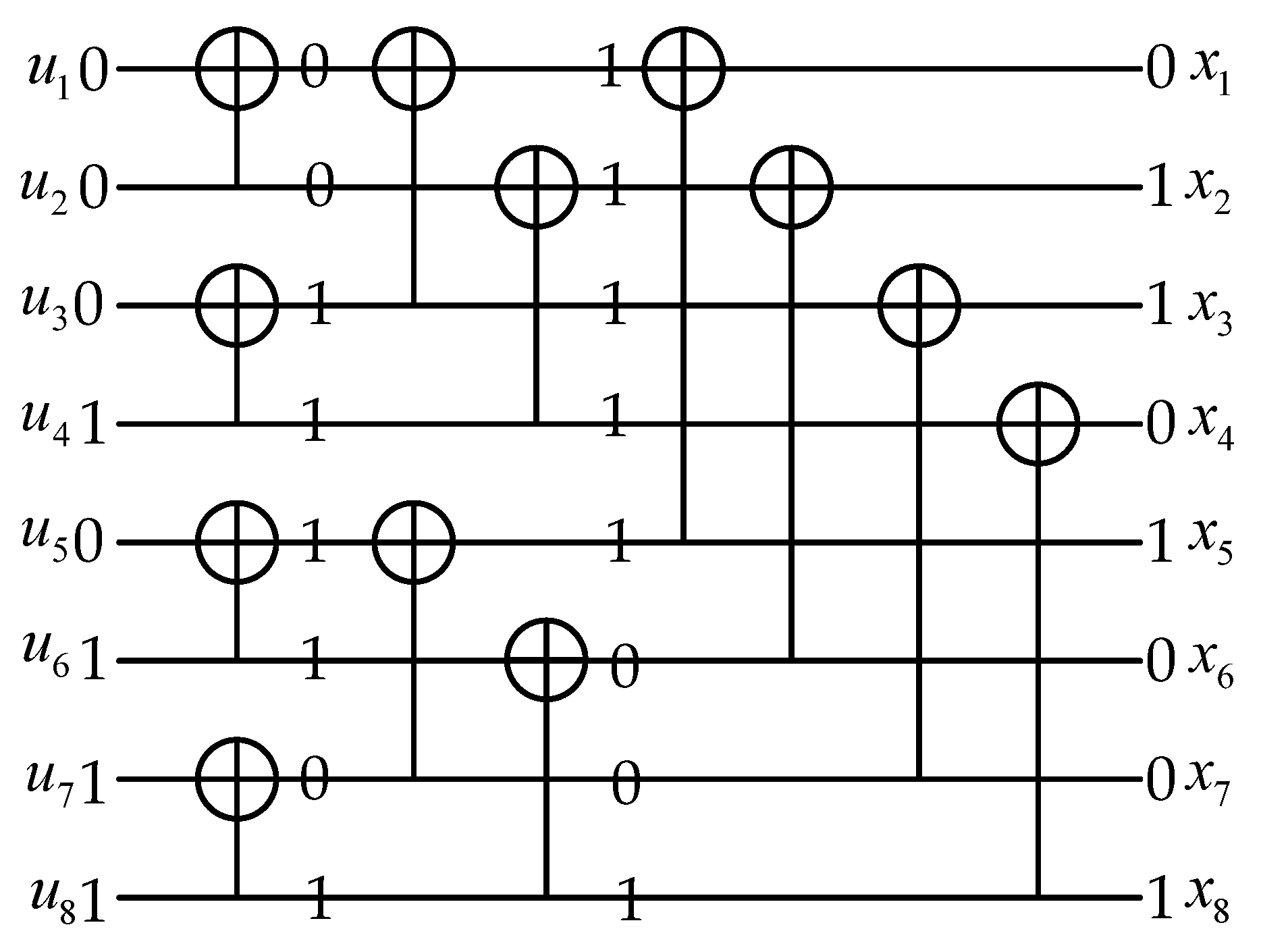
3.2. Polar Codes Encoding and Decoding

Polar coding is based on the phenomenon of channel polarization. As described in Section 3.1, independent channels undergo a process of channel splitting and merging, which transforms them into two types of synthesized subchannels. As the code length increases and the polarization transformation is repeatedly applied, the subchannels gradually polarize into two extreme states: purely noisy channels and noiseless channels. Since purely noisy channels have significantly lower capacity and reliability compared to noiseless channels, polar coding allocates information bits to noiseless subchannels, while redundant frozen bits (commonly set to 0) are assigned to purely noisy subchannels.
However, in practical communication systems, the code length N is always finite, which means the subchannels cannot be fully polarized. As a result, some subchannels exhibit polarization levels between high and low extremes. Consider a binary sequence u 1 N of length N = 2 n ( n 0 ) from set 1 , 2 , , N , a subset of reliable subchannels is selected to form an information set I for encoding K information bits, while the remaining subchannels form the frozen set F . This polar coding problem then becomes a polar code construction problem, as described in Section 4.2. The triplet N , K , I determined through the polar code construction uniquely specifies a set of polar codes, and the corresponding encoding process can be represented as follows:
x 1 N = u 1 N G N
where G N is the generator matrix, defined as follows:
G N = F n
where F represents the Kronecker product, with the specific form as follows:
F = 1 0 1 1
Based on the information set and frozen set, the encoding equation can be rewritten as follows:
x 1 N = u I G N ( I ) u F G N ( F )
Figure 5 illustrates a specific encoding example with parameters 8 , 4 , { 4 , 6 , 7 , 8 } .
The successive cancellation (SC) decoding algorithm is a greedy search method applied to a compact-level code tree. It performs likelihood-based sequential decoding for each bit based on the channel transition probabilities W N , i , 1 i N of the polarized subchannels. Each decoded bit is treated as reliable information and is utilized in subsequent decoding steps to obtain an estimate u ^ 1 N of the original transmitted sequence u 1 N .
W N , i ( y 1 N , u 1 i 1 | u i ) u i + 1 , N χ N i 1 2 N W N ( y 1 N | u 1 N )
W N , i ( y 1 N , u 1 i 1 | u i ) represents the probability of the received signal y and the previously decoded bits u 1 i 1 , given that the current bit u i is 0 or 1. Then, the likelihood ratio (LR) is defined as follows:
L N , i ( y 1 N , u ^ 1 i 1 ) W N , i ( y 1 N , u 1 i 1 | 0 ) W N , i ( y 1 N , u 1 i 1 | 1 )
The decoding decision based on the L R is as follows:
u ^ i 1 , 0 , u i        L N , i ( y 1 N , u ^ 1 i 1 ) 1           L N , i ( y 1 N , u ^ 1 i 1 ) 1 i F
The likelihood values of each polarized subchannel can be recursively derived using Equations (12) and (13).
L N , 2 i - 1 ( y 1 N , u ^ 1 2 i 2 ) = L N / 2 , i ( y 1 N / 2 , u ^ 1 , o 2 i 2 u ^ 1 , e 2 i 2 ) L N / 2 , i ( y N / 2 + 1 N , u ^ 1 , e 2 i 2 ) L N / 2 , i ( y 1 N / 2 , u ^ 1 , o 2 i 2 u ^ 1 , e 2 i 2 ) + L N / 2 , i ( y N / 2 + 1 N , u ^ 1 , e 2 i 2 )
L N , 2 i ( y 1 N , u ^ 1 2 i 1 ) = L N / 2 , i ( y 1 N / 2 , u ^ 1 , o 2 i 2 u ^ 1 , e 2 i 2 ) 1 2 u ^ 2 i 1 L N / 2 , i ( y N / 2 + 1 N , u ^ 1 , e 2 i 2 )
From Equations (12) and (13), it can be seen that the computation of the L R values for N polarized subchannels can be recursively reduced from two sets of L R values of length N / 2 to a computation length of 1. The initial value of the L R is as follows:
L 1 , 1 ( y i ) = W ( y i | 0 ) W ( y i | 1 )
However, in the successive cancellation (SC) decoding process, at each level, only the branch with the higher probability is selected, meaning that if an error occurs at any step, it propagates through the decoding process and cannot be corrected. To improve error correction, an enhanced version of SC decoding, called successive cancellation list (SCL) decoding, is used. Similar to SC, SCL searches the code tree level by level but retains up to LLL candidate paths, increasing decoding accuracy. An even more robust variation is CRC-aided SCL decoding, where a CRC check is applied to filter out the correct codeword among the candidate paths.

4. A Novel Polar Code Construction Method for the UWA Channel

To effectively enhance the performance of the proposed polar-coded OFDM underwater acoustic communication system in Section 5, it is essential to construct optimal polar codes tailored to the specific UWA channel.

4.1. Underwater Acoustic Channel

Accurate modeling of UWA channels has long been one of the major challenges to be overcome in the field of underwater acoustic signal processing. The UWA channel is time-varying, exhibiting pronounced multipath effects and substantial delays, with channel conditions displaying considerable variation across different locations. Nevertheless, within the coherence time, it is reasonable to assume that the UWA channel transfer function will remain constant. In general, the received signal, y ( t ) can be expressed as a function of the transmitted signal, x ( t ) , when it passes through a scattering channel.
y ( t ) = h ( t , τ ) x ( t τ ) d t + N ( t ) = H ( v , τ ) x ( t τ ) e j 2 π v t d v d t + N ( t )
where h represents the time-varying channel impulse response function, H denotes the Fourier transform of h with respect to time, and N ( t ) signifies t -distributed noise with variance σ 2 for the random variable X . By sampling the time domain and assuming that within a data frame of range N the L multipath components remain relatively stable, the discrete time domain model of the received signal can be expressed as follows:
y ( k ) = l = 0 L h ( k , l ) x ( k τ ) + N ( t )
As a consequence of the severe multipath-induced inter-symbol interference, the channel fading coefficient matrix becomes a non-diagonal matrix. The addition of a cyclic prefix (CP) to the OFDM symbol enables the transformation of the channel fading coefficient matrix into a circulant Toeplitz matrix [40]. By employing the fast Fourier transform (FFT), the time domain signal is transformed into the frequency domain, resulting in the following:
Y = H X + N
At this point, H becomes a diagonal matrix, and its diagonal elements H i are given by the following:
H i = l = 0 L h l e j ( 2 π l i / N ) , 0 i N 1
As underwater acoustic channels are subject to temporal-, spatial- and frequency-dependent variations, the estimation of the channel transfer function, denoted by H ( Z ) , represents a challenging undertaking. In practice, within the coherence time, underwater acoustic channels can be regarded as deterministic linear time-invariant filters or deterministic spatiotemporal filters. In light of the aforementioned considerations, the channel transfer function can be expressed as follows:
H ( Z ) = i = 0 M A i × Z τ i / T
where M represents the number of multipath components within the symbol duration of the channel, A i and τ i denote the amplitude and delay of the i -th path, respectively, T represents the sampling period, and   denotes the floor operation [41].
For the sake of convenience, in channel modeling and analysis, it is assumed that the sound speed remains constant in the horizontal direction and that the sound speed is horizontally stratified based on depth. On this basis, the energy distribution and propagation paths of acoustic signals in the underwater acoustic channel can be approximately derived, thereby reducing the complexity of establishing underwater acoustic channel models. Consequently, this study primarily adopts the existing classical oceanic underwater acoustic channel, with an underwater acoustic communication bandwidth of 5 kHz and a sampling frequency of 10 kHz [42,43].
The invariable sound velocity gradient (ISVG) channel represents a uniform environment where sound velocity remains nearly constant, suitable for controlled acoustic experiments.
H ( Z ) = 1 + 0.599971 Z - 20
The negative sound velocity gradient (NSVG) channel represents an environment where sound velocity decreases with depth, causing downward refraction of sound waves.
H ( Z ) = 1 + 0.263112 Z 7 + 0.151214 Z 39 + 0.391599 Z 67
The positive sound velocity gradient (PSVG) channel represents an environment where sound velocity increases with depth, leading to upward refraction of sound waves.
H ( Z ) = 0.734189 + Z 13 0.406511 Z 14 0.295130 Z 55
Although this model does not explicitly incorporate external parameters such as temperature, salinity and water depth, it inherently captures the impact of sound speed variation with depth, which is a key factor affecting underwater acoustic signal propagation. Additionally, the model serves as a widely applicable benchmark for evaluating OFDM-based underwater communication systems. In the future, we plan to further refine the model by integrating real-world measurement data to enhance its accuracy and applicability.
When the system adopts QPSK modulation, the transition probability of the underwater acoustic channel can be expressed by Equation (35):
P r ( x i = 1 | y i , h i ) = x c i 1 42.3423 σ ( 2 ( Y i H i X ) 2 σ 2 + 5 ) 2.75
P r ( x i = 0 | y i , h i ) = x c i 0 42.3423 σ ( 2 ( Y i H i X ) 2 σ 2 + 5 ) 2.75
The formula for calculating the log-likelihood ratio is as follows:
L L R i ( x , y ) = ln P r ( x i = 0 | y ) P r ( x i = 1 | y )
Upon substituting Equations (23) and (24) into Equation (25), the following result is obtained:
L L R i ( x i | y i , h i ) = ln P r ( x i = 0 | y i , h i ) P r ( x i = 1 | y i , h i ) = ln x c i 0 P r ( Y i | X i ) x c i 1 P r ( Y i | X i ) = ln x c i 0 ( 5 σ 2 + 2 ( Y i - H i X ) ) 2.75 x c i 1 ( 5 σ 2 + 2 ( Y i - H i X ) ) 2.75
where X represents the transmitted complex signal, Y represents the receiver’s estimate of the transmitted complex signal, L L R i denotes the output for the i -th bit of the corresponding symbol, and σ 2 is the noise power for each symbol. c i 0 and c i 1 represent the sets of symbols where the i -th bit equals 0 and 1, respectively.

4.2. Novel Polar Code Construction Method for the UWA Channel

In this section, we present a novel polar code construction method based on the base-adversarial polarization weight (BPW) channel polarization algorithm with details of the specific implementation. As described in Section 3.1, the reliability of polarized subchannels is determined by their channel capacities, making it essential to accurately evaluate these capacities after polarization. Traditional methods, such as the Bhattacharyya parameter, density evolution, Gaussian approximation and Monte Carlo, are highly dependent on specific channel parameters, leading to inconsistent polarization outcomes. To address the challenges caused by channel parameter dependence and the computational complexity of these algorithms, Huawei [44] proposed the polarization weight (PW) method in 3GPP RAN1 #86 to generate an ordered sequence of subchannels by reliability. The subchannel reliability order, independent of SNR, is determined by calculating the PW for each subchannel and storing the resulting ordered index sequence S 0 N max 1 for a polar code with a maximum code length of N max . The PW of each subchannel is computed as a weighted sum in the binary domain based on its corresponding subchannel index. Let a synthetic channel, indexed as x , have an n - bit binary expansion, B = ( b n 1 , , b 1 , b 0 ) , where the most significant bit is positioned to the left. The polarization weight can thus be defined as follows:
W i = k = 0 n 1 B k α k
where α represents the base of the expansion. In order to replace the Gaussian approximation algorithm, the 3GPP RAN87 meeting ultimately determined that a = 2 1 / 4 . The PW method offers a low-complexity and comprehensive ranking methodology for evaluating synthetic channel reliability. However, the PW algorithm utilizes a single fixed base, which does not differentiate between varying levels of polarization. To address this limitation, Huawei [45] proposed the HPW method, which incorporates the contributions of different binary digits into the evaluation of polarized channels, thereby refining the distinctions between individual subchannels. This refinement is mathematically expressed in Equation (28).
W i = k = 0 n 1 ξ Ζ B k α k / 4 ξ
Although the HPW method incorporates the contributions of different binary digits into the evaluation of polarized channels to refine the subtle variations between individual subchannels, its flexibility remains constrained by the limitations of the zero-order base. To overcome this limitation, extending the single base to a more general base b offers an alternative approach for achieving a more flexible representation of sequence order refinement. After introducing the base extension, EPW [45] can be expressed as follows:
W i = k = 0 n 1 B k × ( α k + b × d k )
where the variable b represents the weight factor associated with the flexible base d .
The incorporation of a new base b in Equation (29) introduces an additional degree of freedom, enhancing the flexibility in describing the PW relationships among subchannels. However, the PW family Formulas (27)–(29) inherently possess a symmetric structure, where the ordering sequence in the first half remains identical to that in the second half, i.e., S 0 N / 2 1 = S N / 2 N 1 N / 2 . To further extend the expressiveness of the PW framework, a novel parameter, termed the symmetry-breaking point B c , is introduced by Huawei. This parameter effectively disrupts the inherent symmetry within a periodic span of 2 c + 1 , thereby refining the differentiation among subchannels and enhancing the overall adaptability of the construction methodology. Then, the ordering sequence of the first half and the second of S 2 c + 1 j 2 c + 1 ( j + 1 ) 1 will not be the same, where j = [ 0 , 1 , 2 , , N / ( 2 c + 1 ) 1 ] . The fundamental formula is expressed as follows:
W i = k = 0 n 1 B k × ( α k + b × d k B c × e × g k B f × h × l k )
where g and l represent the extended bases, while e and h denote the corresponding weight factors of the bases. The symmetry-breaking points are indicated by the symbols B c and B f .
However, the above method fails to sufficiently refine the differences between subchannels. Its zero-order base α exhibits an exponentially increasing contribution from the higher-order bits in the binary expansion as k increases. The dominant influence of higher-order bits results in the polarization weight being primarily determined by these bits, while the impact of lower-order bits is weakened. Consequently, the contributions of adjacent higher-order bits become similar, leading to a reduction in subchannel distinguishability. To address this issue, a novel adversarial parameter β with a different power structure is introduced into Equation (30), proposing a novel, robust and efficient polar code construction (NREPCC) method using the base-adversarial polarization weight (BPW) channel polarization algorithm for UWA channel.
W i = k = 0 n 1 B k × ( α k β k + 1 + b × d k B c × e × g k B f × h × l k )
In the above equation, the exponent of β corresponds to the indices of adjacent higher-order bits, which slightly attenuates the contribution of the zero-order base α associated with higher-order bits. This effect is opposite to that of α k , creating a certain degree of cancellation, thereby ensuring a more uniform contribution across different polarization levels. Compared to the EPW method, the BPW approach effectively reduces the dominance of higher-order bits, enhances the influence of lower-order bits, and consequently improves the differentiation among subchannels to a certain extent. Concurrently, to augment the construction efficacy of polar codes in underwater acoustic channels, the zero-order base no longer utilizes the fixed parameters employed in Gaussian channel-based constructions. This modification serves to overcome the performance limitations of the Gaussian approximation method, thereby paving the way for a significant performance breakthrough.

5. Polar-Coded UWAC OFDM System Model and Improved Synchronization Algorithm

5.1. Ocean Noise Model

The determination of ocean noise models is of great significance for the advancement of underwater acoustic communication. This not only provides a more accurate simulation environment but also has a direct impact on the accuracy of communication decoding. To date, a considerable body of research has been conducted into a range of ocean environments, including shallow seas. Research findings indicate that the distribution of underwater noise is non-Gaussian. The present study primarily analyses the characteristics of ocean noise by accessing the noise dataset published by the National Oceanic and Atmospheric Administration (NOAA) [46]. Figure 6 illustrates the waveform corresponding to the selected underwater acoustic noise (UWAN) data over time.
The UWAN data was analyzed using the fitting toolbox in MATLAB R2023a, with Gaussian, GMM and t -distribution fitted to it, as illustrated in Figure 7. To quantitatively evaluate the fitting performance, we employed the Akaike Information Criterion (AIC) and Bayesian Information Criterion (BIC). The results, as shown in Table 1, demonstrate that the t-distribution model achieves significantly lower AIC and BIC values compared to the Gaussian model and GMM, indicating a better fit to the actual underwater noise data. The t-distribution model offers a simpler yet more accurate representation of underwater noise. While GMM can also capture non-Gaussian characteristics, it requires a larger number of parameters and is computationally more complex. The fitting results demonstrate that the UWAN distribution in the target marine area does not adhere to the characteristics of a standard Gaussian noise distribution. The t-distribution model, on the other hand, provides a balance between accuracy and computational efficiency, making it more suitable for simulating the UWAN, with an estimated degree of freedom of approximately 4.5.
The probability density function (PDF) of the t -distribution can be expressed as follows [47]:
p T ( t , d ) = Γ ( d + 1 2 ) π d Γ ( d 2 ) 1 + t 2 d d + 1 2
where Γ represents the gamma function, while d denotes the degrees of freedom associated with the t -distribution. The value of d exerts a considerable influence on the shape of the probability density function (PDF). A reduction in the value of d results in the tails of the distribution becoming heavier; conversely, an increase in d leads to narrower tails. For sufficiently large degrees of freedom, the probability density function of the t -distribution converges to that of a Gaussian distribution. The term p T ( t , d ) denotes the probability of observing a specific value of the t -distribution with d degrees of freedom. The PDF expressed in Equation (32) has a mean of zero when d > 2 , and its variance is given by d / ( d 2 ) . To establish a model for a random variable X with variance σ 2 , the variable can be transformed as follows [48]:
t = d ( d 2 ) σ 2 x
Therefore, a new scaled PDF function can be expressed as follows:
p T ( x , d ) = Γ ( ( d + 1 ) / 2 ) ( d 2 ) π Γ ( d / 2 ) σ 1 + x 2 ( d 2 ) σ 2 ( d + 1 ) / 2
When d = 4.5 , the PDF can be expressed as follows:
p T ( x , d * ) = 42.3423 σ 5 + 2 x 2 σ 2 2.75

5.2. System Structure

OFDM is a multicarrier modulation technique that transforms a serial data stream into parallel data streams, which are then transmitted over orthogonal subcarriers. It effectively balances transmission efficiency, spectrum utilization and resistance to multipath interference. The narrow bandwidth and severe multipath effects of underwater acoustic channels impose significant constraints on the development of high-speed underwater acoustic communication. Therefore, developing and utilizing OFDM technology for underwater acoustic communication represents a meaningful and effective approach. To sustain the proposed polar code construction method and analyze the application performance of polar codes in the UWAC OFDM system, we establish a practical and reliable simulation system for OFDM communication technology using polar codes, named the polar-coded UWAC OFDM system, as illustrated in Figure 8. The system is comprised of two principal components. At the transmitter, the random sequence of 0 s and 1 s generated by the information source is initially encoded using polar codes with the objective of enhancing reliability. Subsequently, the encoded bits are mapped onto a constellation. Then, the signal is transformed into a parallel representation incorporating pilot symbols, which is then subjected to an IFFT operation. A cyclic prefix (CP) is incorporated to mitigate inter-symbol interference (ISI). Finally, the signal is converted back into a serial signal, combined with the training sequence, and transmitted through the underwater acoustic channel. At the receiver, the reverse operations are performed. The received signal undergoes synchronization processing, followed by an FFT operation. Channel estimation and equalization are carried out based on the training sequence and inserted pilot symbols. Finally, the signal is demodulated and decoded to recover the original information.

5.3. Synchronization Algorithm

The selection of the synchronization algorithm is of paramount importance in the research of underwater acoustic communication systems. At present, the Park algorithm [49], a prevalent clock synchronization technique in OFDM systems, is instrumental in enhancing the communication efficiency and stability of the system. By minimizing inter-subcarrier interference, this algorithm effectively addresses inter-symbol interference and inter-carrier interference caused by timing deviations. The Park algorithm differs from the original SC algorithm [50] and the min algorithm [51] in that it introduces new preamble codes and correlation methods to achieve pulse-shaped timing metrics. The PN sequence of the preamble code is given by the following expression:
P p r o = [ C N / 4        D N / 4        C N / 4        D N / 4 ]
where C N / 4 represents samples of length N / 4 generated by performing the IFFT on the PN sequence. C N / 4 denotes the conjugate of C N / 4 . To obtain a pulse-shaped timing metric, D N / 4 is designed to be symmetric to C N / 4 .
To leverage the symmetry of D N / 4 with respect to C N / 4 and maximize the difference between two adjacent values of the timing metric, the Park algorithm introduces a new timing metric, expressed as follows:
M p ( d ) = | P ( d ) | 2 ( R ( d ) ) 2
where
P ( d ) = k = 0 N / 2 y ( d k ) y ( d + k )
R ( d ) = k = 0 N / 2 | y ( d + k ) | 2
In traditional OFDM synchronization algorithms, represented by the Park algorithm, squared normalization is typically employed to eliminate any impact of signal power. However, when the noise model is altered from a Gaussian distribution to a t -distribution, the application of squared normalization has a detrimental impact on the synchronization performance. The heavy-tailed nature of the t -distribution results in the emergence of higher amplitude noise points, and the squaring operation serves to further amplify this noise, thereby disrupting the accuracy of timing synchronization. This study proposes an improved version of the Park algorithm, in which key formulas have been adjusted with the aim of enhancing the algorithm’s robustness and accuracy in noise environments that resemble a t -distribution. The precise formulation is as follows:
M p r o ( d ) = | P ( d ) | 2 R ( d )
where
P ( d ) = k = 0 N / 2 y ( d k ) y ( d + k ) + y ( d + k - N / 2 ) y ( d + k ) ,
R ( d ) = k = 0 N / 2 | y ( d + k ) + y ( d - k ) | 2
P ( d ) represents the sum of two distinct product pairs between two adjacent sequences of length N / 2 , which can achieve the maximum number of unique product pairs at the optimal position. Figure 9a illustrates correlation peak detection for synchronization algorithms with d = 4.5 and SNR = 8. From the Figure 9a, it can be observed that the proposed Park algorithm demonstrates higher synchronization accuracy and robustness compared to the traditional Park algorithm. The traditional algorithm is significantly affected by non-Gaussian noise, resulting in a lower normalized correlation peak (around 0.9) at the correct synchronization index 493, making it a secondary peak, with the correlation being severely influenced by noise. In contrast, the improved algorithm significantly reduces noise interference, producing a smoother correlation curve that is primarily concentrated around the true synchronization point and achieves the highest correlation peak at index 493. Figure 9b illustrates the performance comparison of the timing synchronization algorithm before and after the improvement. Mean square error (MSE) was used as the evaluation metric for simulations conducted under an ISVG channel with t -distributed noise characterized by d = 4.5 . This indicates that the proposed Park algorithm is better suited for non-Gaussian noise environments.

6. Simulation and Analysis

This section is primarily concerned with the simulation analysis of the aforementioned polar-coded UWAC OFDM system, which is conducted using the MATLAB R2023a simulation platform and the environment described in Table 2. The analysis encompasses the evaluation of the resilience of the coarse synchronization algorithm, a comparison of the performance of the polar code construction method before and after enhancements, an investigation of the simulation analysis under three classical ocean channel models, a comparison with three other coding methods, and a verification of the resilience of the proposed NREPCC method. The simulation parameters of the polar-coded UWAC OFDM system are detailed in Table 3.

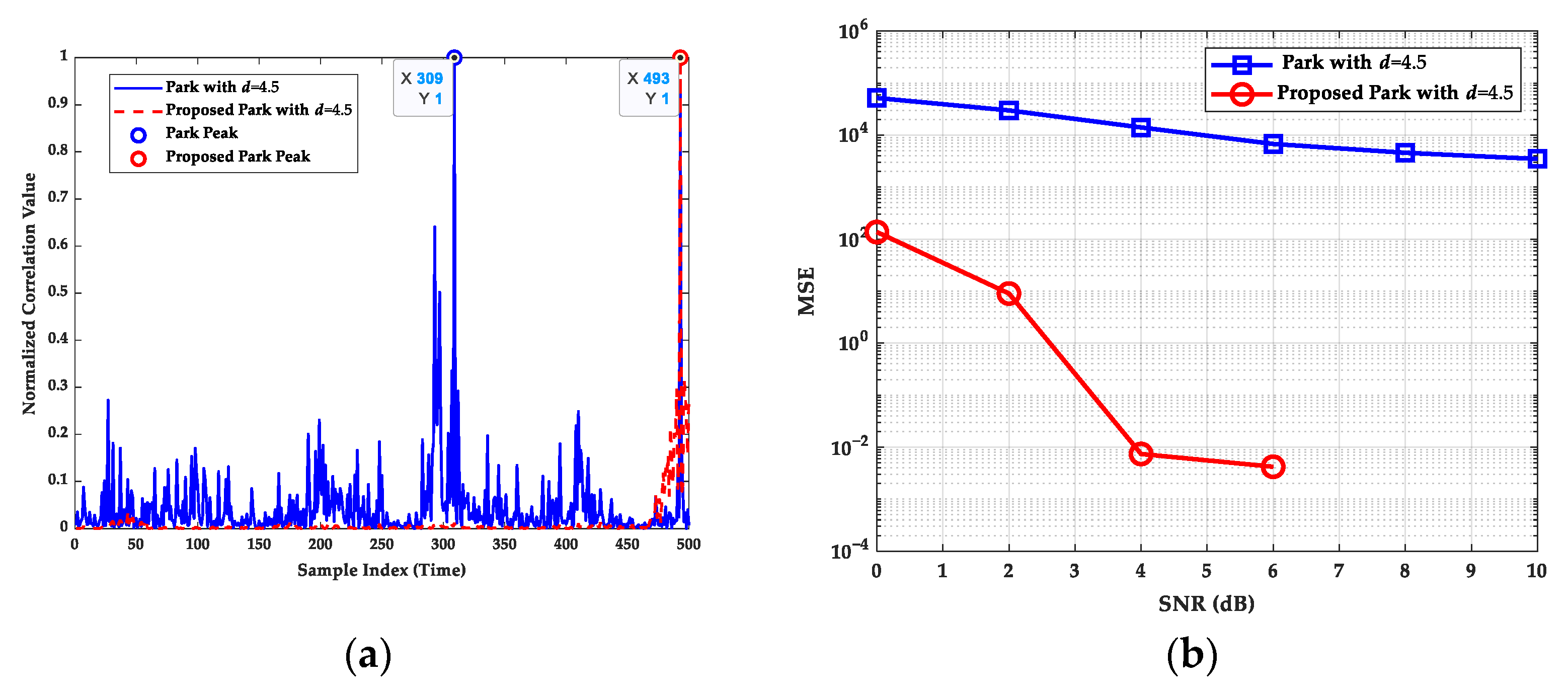
6.1. Synchronization Algorithm Robustness Verification

This section performs robustness verification and analysis of the synchronization algorithm proposed in Section 5.3, with a particular focus on simulation validation under ISVG channels with noise environments of varying degrees of freedom, as illustrated in Figure 10. The results demonstrate that the enhanced synchronization algorithm exhibits robust performance across diverse noise environments with varying degrees of freedom. It achieves a mean square error on the order of 10 2 at approximately 6 dB, ensuring reliable detection of underwater acoustic communication signals in complex noise environments that resemble t -distribution.

6.2. Effectiveness Verification of Polarization Construction Methods

This section aims to validate the effectiveness of the proposed NREPCC method by comparing its performance with that of the Gaussian approximation method, the original PW algorithm and the EPW algorithm. Simulations are conducted under the ISVG channel with t -distributed background noise and a degree of freedom d = 4.5 , using the bit error rate (BER) as the comparison parameter. As illustrated in Figure 11, the performance of polar codes constructed using the PW method is inferior to that of the GA construction method, with a notable discrepancy between the two. The proposed NREPCC method, which introduces a novel zero-order base and leverages adversarial parameters to mitigate the dominance of higher-order bits, addresses the limitations of the GA construction method and results in enhanced performance. In comparison to the GA method, the proposed NREPCC method demonstrates an improvement in performance of approximately 1.5 dB at a BER of 10 3 , thereby substantiating the efficacy of this approach.

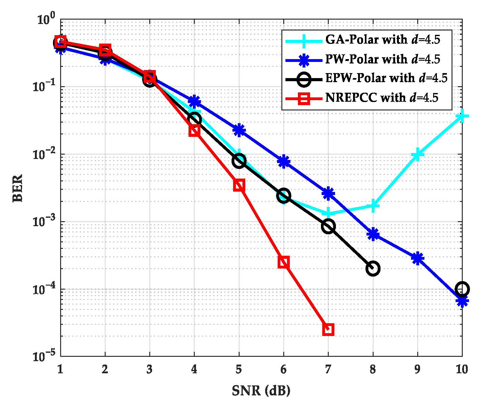
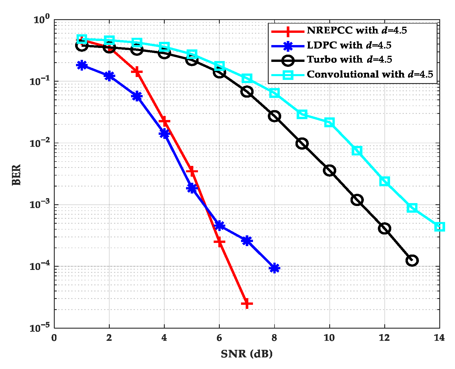
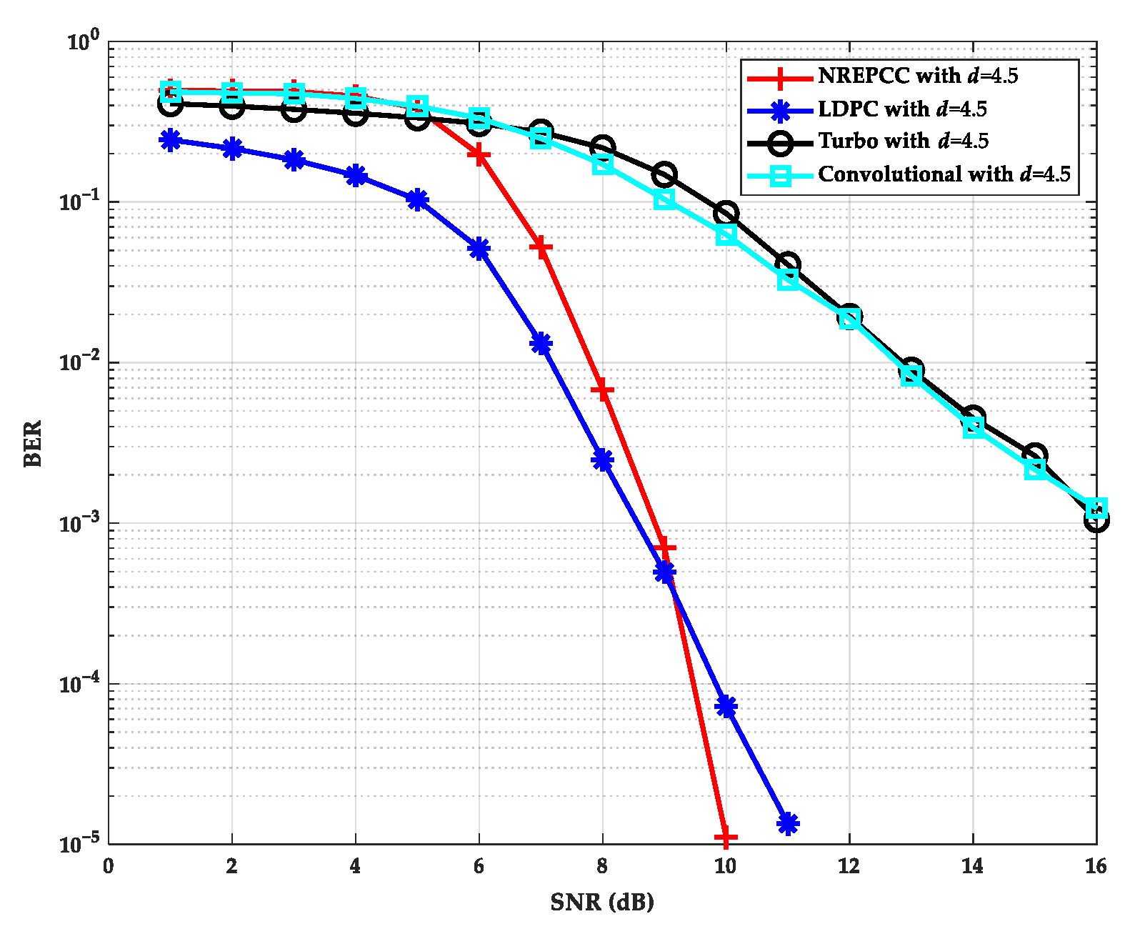
6.3. Performance Comparison of Different Coding Methods

This section presents a comparative analysis of the performance of polar codes, LDPC codes, turbo codes and convolutional codes under three distinct types of oceanic channel models: ISVG, NSVG and PSVG. Simulations were conducted with a code length of N = 1024 and a code rate of 1/2 across all coding schemes. For polar codes, polarization construction employs the adversarial PW method, with the decoding performed using the CA-SCL algorithm configured with a list size of L = 16 . LDPC codes are decoded using the min-sum algorithm (MSA) with 10 iterations. Turbo codes use a generator matrix 37 , 21 and perform 10 decoding iterations. Convolutional codes are configured with a constraint length of 7 and decoded using the Viterbi soft-decision algorithm. All simulations adopt QPSK modulation under a t -distributed noise environment with a degree of freedom of 4.5. The simulation results are shown in Figure 12, Figure 13 and Figure 14.
The results of the simulations indicate that polar codes display exceptional performance across the three conventional oceanic channel models. In particular, polar codes exhibit a distinct advantage in terms of absolute coding gain when compared to turbo codes and convolutional codes, irrespective of the underlying channel conditions. When the BER requirement is on the order of 10 4 , polar codes with a code length of N = 1024 can provide at least a 4 dB coding gain. In the ISVG channel, the performance of polar codes begins to exceed that of LDPC codes when the signal-to-noise ratio (SNR) reaches 6 dB. At this juncture, LDPC codes reach a BER floor, wherein the error rate remains largely unaltered as the SNR rises. In contrast, polar codes demonstrate a notable 1 dB performance gain. In the PSVG channel, polar codes demonstrate performance on par with LDPC codes at an SNR of 9 dB. However, as the SNR increases, polar codes exhibit a significant performance advantage over LDPC codes, with a gain of up to 0.5 dB. In the NSVG channel, the performance of polar codes is slightly inferior to that of LDPC codes. However, due to the impact of complex noise, the error rate of LDPC codes exhibits a reverse growth trend as the SNR increases. In conclusion, polar codes demonstrate the capacity to sustain robust performance gains in the presence of complex noise, exhibiting a distinct advantage over turbo codes and convolutional codes while exhibiting performance comparable to that of LDPC codes. At low SNR, the BER curves of LDPC codes are consistently below those of polar codes across the three oceanic channels. This indicates that LDPC codes have certain advantages under low-SNR conditions, which can be attributed to their inherent encoding and decoding capabilities. At these SNRs, the serial decoding structure of polar codes constrains their performance due to the propagation of errors. Nevertheless, as the SNR increases, polar codes gradually approach and eventually surpass the performance of LDPC codes, which is determined by the asymptotic performance of polar codes.
Furthermore, an analysis was conducted on the encoding and decoding complexity of the aforementioned channel coding methods, as illustrated in Table 4.
The experimental results obtained under different oceanic channel conditions demonstrate that polar codes exhibit outstanding performance and significant advantages in terms of encoding and decoding complexities. In particular, the recursive structure of polar codes gives rise to an encoding complexity of O N l o g N , which is markedly lower than the O N 3 encoding complexity of LDPC codes. With regard to decoding, although the CA-SCL algorithm utilized by polar codes has a complexity of O N l o g N , it remains lower than the O d v × d c × N × I complexity of the MSA algorithm employed by LDPC codes, where I represents the number of iterations and d v , d c denote the node degrees. The reduced decoding complexity of polar codes enables them to attain substantial performance enhancements in regions of high SNR and maintain robust performance in complex noise environments. In contrast, while turbo codes and convolutional codes offer advantages in terms of low-complexity encoding, they exhibit significantly inferior performance compared to that of polar codes and LDPC codes. It is evident that polar codes offer a more comprehensive set of benefits.

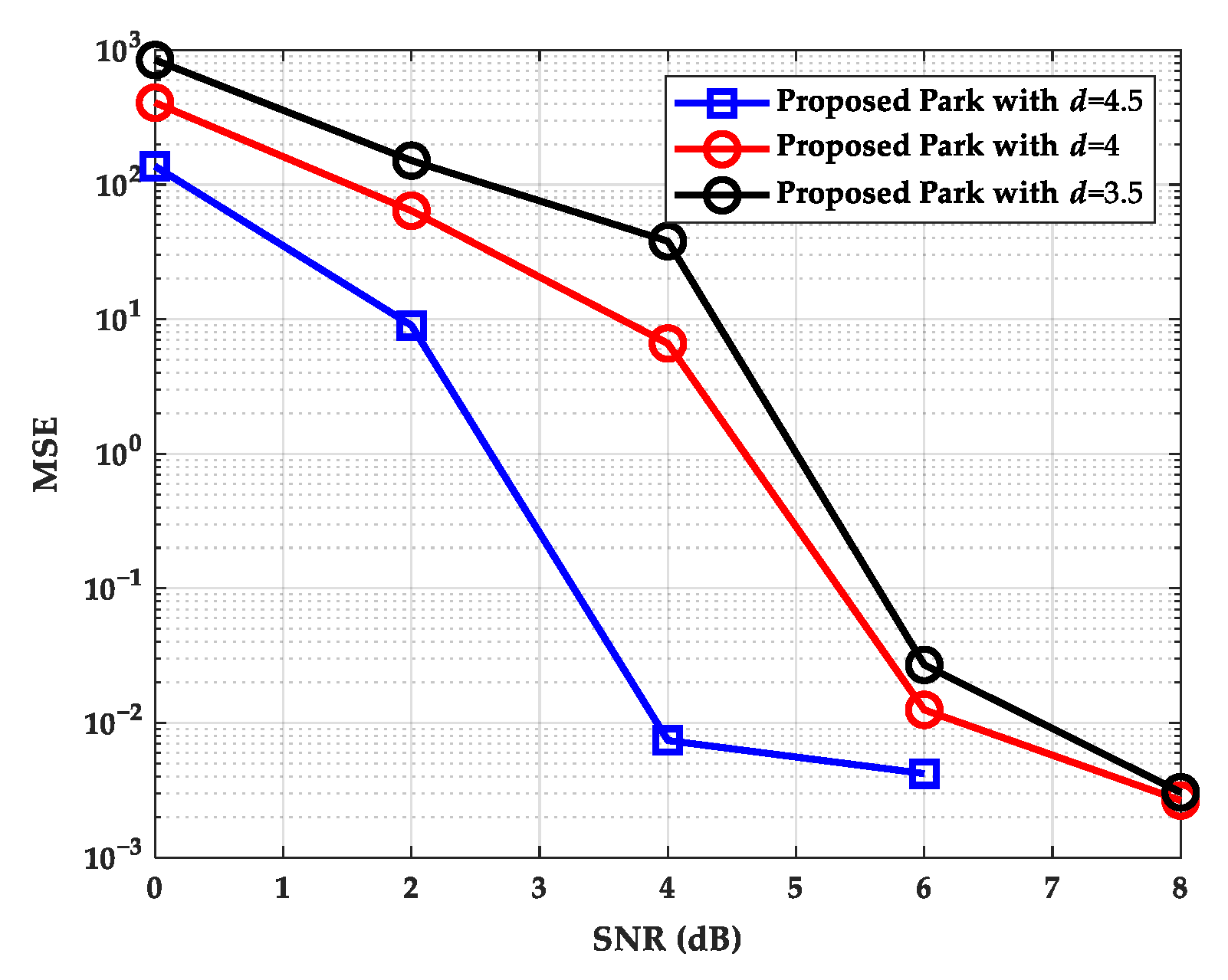
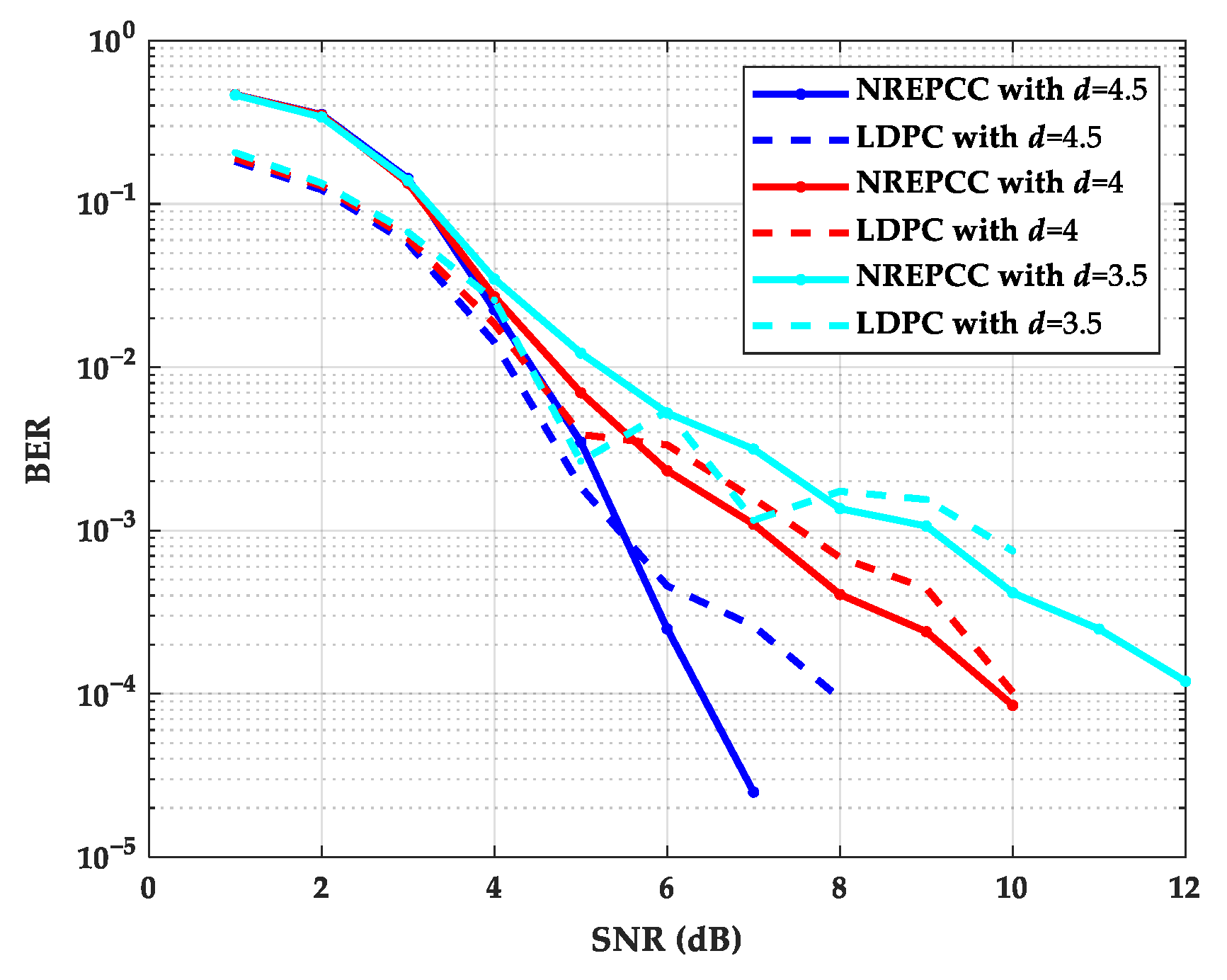
6.4. Impact of Degrees of Freedom d on Coding Performance

In communication systems, the presence of noise is an unavoidable phenomenon. The characteristics of this noise can have a profound impact on the performance of coding techniques. In underwater acoustic communication, noise often deviates from the Gaussian assumption, instead exhibiting impulsive and heavy-tailed characteristics, which can be better modeled using a t -distribution. The degree of freedom ( d ) in the t-distribution plays a crucial role in determining the shape of the noise distribution. A lower d (e.g., d = 3.5 ) results in a heavier tail, meaning a higher probability of extreme noise values, which can lead to severe interference in signal transmission. A higher d (e.g., d = 4.5 ) makes the noise distribution closer to a Gaussian, reducing the occurrence of extreme noise spikes and leading to more stable communication. This section examines the impact of varying d values on the performance of polar codes, comparing their behavior against LDPC codes under different noise conditions. The simulation results are illustrated in Figure 15.
The results indicate that the BER performance of polar and LDPC codes strongly depends on the degree of freedom d in the t-distribution. When d is small (e.g., d = 4.5 ), the noise is highly impulsive, causing a significant increase in BER for both coding schemes. When d increases to 4.5, the BER decreases, as the noise becomes less extreme, making signal detection and error correction more reliable. Under all tested d values, polar codes outperform LDPC codes, demonstrating greater robustness to heavy-tailed noise conditions. The advantage of polar codes is particularly noticeable in low d conditions, where LDPC codes suffer from rapid BER degradation due to their sensitivity to extreme noise events. This suggests that the NREPCC method used in polar code construction effectively mitigates the impact of heavy-tailed noise, validating its applicability in underwater acoustic communication scenarios. To further quantify this impact, we analyze the BER performance gap between polar and LDPC codes under different d values. At d = 3.5 , the BER of LDPC codes increases significantly, while polar codes maintain a lower BER, showing stronger resilience to noise spikes. At d = 4.5 , the BER of both coding schemes improves, but the improvement is more pronounced for polar codes, suggesting that the BPW-based method provides additional noise robustness. These results confirm that the degree of freedom d in the t -distribution has a direct impact on coding performance and polar codes offer superior resilience to non-Gaussian noise environments, making them a more suitable choice for underwater acoustic communication.

6.5. Impact of Code Rates on Coding Performance

The code rate exerts considerable influence on the polar-coded UWAC OFDM system. This section principally examines the impact of disparate code rates on the encoding performance of polar codes, as illustrated in Figure 16. The simulation results demonstrate that polar codes exhibit a distinct coding gain advantage over LDPC codes under low code rate conditions. Once the construction algorithm and code length have been established, the ranking of the polarized subchannels is also determined. At low code rates, the transmitted information can be allocated to the polarized subchannels with the greatest channel capacity. Nevertheless, the constraints of a finite code length preclude the complete polarization of subchannels. In conditions of higher code rates, the performance of polar codes is found to be inferior to that of LDPC codes. It is, therefore, evident that in practical applications, the selection of an appropriate code rate and code length is of paramount importance in order to achieve highly reliable underwater acoustic communication.

7. Conclusions

In this study, we developed and validated the polar-coded UWAC OFDM system, specifically designed to address the multipath and time-varying channel characteristics commonly found in ocean environments. Specifically, we present a novel, robust and efficient polar code construction method using the base-adversarial polarization weight (BPW) algorithm, named the NREPCC method, for the ISVG, NSVG and PSVG oceanic channel models. Further, combined with a more realistic t -distribution noise model, an improved synchronization algorithm is proposed for packet detection, which effectively enhances the communication efficiency and stability of the polar-coded UWAC OFDM system. Simulation results demonstrated that the NREPCC method exhibited excellent performance across all tested channels. In comparison to LDPC, turbo and convolutional codes, polar codes demonstrated a reduced encoding and decoding complexity while exhibiting enhanced performance gains. It is noteworthy that polar codes demonstrated superior performance to LDPC codes by approximately 0.5~1 dB in the PSVG and ISVG channels while exhibiting comparable performance in the NSVG channels. Fortunately, this superior performance was achieved while maintaining a simpler structure and lower complexity. These characteristics illustrate the potential advantages of polar codes in high-speed, real-time oceanic communication systems. Moreover, polar codes show strong robustness in complex noise environments with varying degrees of freedom, thereby substantiating the efficacy and viability of the adversarial PW approach in underwater acoustic communication applications.
While the proposed NREPCC method and polar-coded UWAC OFDM system have demonstrated promising results in simulation, several directions for future research can further enhance their practical applicability. First, real-world underwater experimental testing is essential to validate the performance of the proposed methods in actual oceanic environments. Such experiments will provide valuable insights into the robustness of the system under realistic conditions, including varying water temperatures, salinity levels and multipath effects. Second, the development of adaptive polar code construction methods that can dynamically adjust to changing channel conditions will be a key focus. This includes exploring machine learning techniques to optimize the selection of adversarial parameters in real time. Third, the integration of the proposed system with emerging technologies, such as the Internet of underwater things (IoUT), will be investigated to enable seamless communication in large-scale underwater networks. Finally, the computational efficiency of the NREPCC method can be further improved by exploring hardware acceleration techniques, such as FPGA or GPU implementations, to meet the low-latency requirements of real-time underwater communication. These future research directions aim to bridge the gap between theoretical advancements and practical deployment, ultimately contributing to the development of reliable and efficient underwater acoustic communication systems.
In conclusion, this study has not only validated the potential of polar codes in complex ocean environments but has also furnished valuable technical insights for future coding strategies in underwater communication systems, particularly in scenarios requiring high reliability and low error rates. Further work will concentrate on the refinement of polar code construction methods and the implementation of adaptive adjustments to accommodate a more extensive range of oceanic communication conditions and requirements.

Author Contributions

J.X. and Z.L. proposed the main ideas, wrote the paper, designed the description framework and conducted the simulations. H.W. and W.W. provided guidance for the work, reviewed and revised the paper and acquired funding. X.C., X.M., Y.Z., B.H. and J.M. assisted in testing the code and checked the paper. All authors have read and agreed to the published version of the manuscript.

Funding

This study is supported by the National Natural Science Foundation of China (Nos. 52201403, 52331012, 52201401, 52472347, 52071200, 52102397), the Chenguang Program of Shanghai Education Development Foundation and Shanghai Municipal Education Commission (No. 23CGA61, 24CGA52), the National Key Research and Development Program (No. 2021YFC2801002), the Shanghai Committee of Science and Technology, China (No. 23010502000), the Changzhou Science and Technology Committee (No. CJ20240068).

Institutional Review Board Statement

Not applicable.

Data Availability Statement

Data will be made available upon request.

Acknowledgments

The authors would like to thank anyone who supported the review of this paper.

Conflicts of Interest

Author Bing Han was employed by the company Shanghai Ship and Shipping Research Institute Co., Ltd. The remaining authors declare that the research was conducted in the absence of any commercial or financial relationships that could be construed as a potential conflict of interest.

Abbreviations

The following abbreviations are used in this manuscript:
UWACunderwater acoustic channel
NREPCCnovel, robust and efficient polar code construction
BPWbase-adversarial polarization weight
ISVGinvariable sound velocity gradient
NSVGnegative sound velocity gradient
PSVGpositive sound velocity gradient
OFDMorthogonal frequency division multiplexing
IoTInternet of things
BERbit error rate
UWAunderwater acoustic
LDPClow-density parity-check
CRCcyclic redundancy check
SCsuccessive cancellation
SCLsuccessive cancellation list
SSPsound speed profile
BECbinary erasure channel
LRlikelihood ratio
PWpolarization weight
HPWhigher order polarization weight
EPWextended polarization weight
CPcyclic prefix
FFTfast Fourier transform
QPSKquadrature phase shift keying
PDFprobability density function
CA-SCLcyclic redundancy check-aided successive cancellation list
MSAmin-sum algorithm

References

  1. Zhu, Z.; Zhou, Y.; Wang, R.; Tong, F. Internet of Underwater Things Infrastructure: A Shared Underwater Acoustic Communication Layer Scheme for Real-World Underwater Acoustic Experiments. IEEE Trans. Aerosp. Electron. Syst. 2023, 59, 6991–7003. [Google Scholar] [CrossRef]
  2. Mishachandar, B.; Vairamuthu, S. An Underwater Cognitive Acoustic Network Strategy for Efficient Spectrum Utilization. Appl. Acoust. 2021, 175, 107861. [Google Scholar] [CrossRef]
  3. Jarrot, A.; Gelman, A.; Choi, G.; Speck, A.; Strunk, G.; Croux, A.; Osedach, T.P.; Vannuffelen, S.; Ossia, S.; Vincent, J.; et al. High-Speed Underwater Acoustic Communication for Multi-Agent Supervised Autonomy. In Proceedings of the 2021 Fifth Underwater Communications and Networking Conference (UComms), Lerici, Italy, 31 August–2 September 2021; pp. 1–4. [Google Scholar]
  4. Beaujean, P.-P.J. High-Speed High-Frequency Acoustic Modem for Image Transmission in Very Shallow Waters. In Proceedings of the OCEANS 2007-Europe, Aberdeen, UK, 18–21 June 2007; pp. 1–6. [Google Scholar]
  5. Stojanovic, M.; Preisig, J. Underwater Acoustic Communication Channels: Propagation Models and Statistical Characterization. IEEE Commun. Mag. 2009, 47, 84–89. [Google Scholar] [CrossRef]
  6. Yang, T. Properties of Underwater Acoustic Communication Channels in Shallow Water. J. Acoust. Soc. Am. 2012, 131, 129–145. [Google Scholar] [CrossRef]
  7. Qarabaqi, P.; Stojanovic, M. Statistical Characterization and Computationally Efficient Modeling of a Class of Underwater Acoustic Communication Channels. IEEE J. Ocean. Eng. 2013, 38, 701–717. [Google Scholar] [CrossRef]
  8. Wang, B.; Wang, Y.; Li, Y.; Guan, X. Underwater Acoustic Communications Based on OCDM for Internet of Underwater Things. IEEE Internet Things J. 2023, 10, 22128–22142. [Google Scholar] [CrossRef]
  9. Feng, C.; Luo, Y.; Zhang, J.; Li, H. An OFDM-Based Frequency Domain Equalization Algorithm for Underwater Acoustic Communication with a High Channel Utilization Rate. J. Mar. Sci. Eng. 2023, 11, 415. [Google Scholar] [CrossRef]
  10. Jiang, W.; Tao, Q.; Yao, J.; Tong, F.; Zhang, F. R&D of a Low-Complexity OFDM Acoustic Communication Payload for Micro-AUV in Confined Space. EURASIP J. Adv. Signal Process. 2022, 2022, 64. [Google Scholar]
  11. Cuji, D.A.; Stojanovic, M. Transmit Beamforming for Underwater Acoustic OFDM Systems. IEEE J. Ocean. Eng. 2023, 49, 145–162. [Google Scholar] [CrossRef]
  12. Li, B.; Zhou, S.; Stojanovic, M.; Freitag, L.; Willett, P. Multicarrier Communication over Underwater Acoustic Channels with Nonuniform Doppler Shifts. IEEE J. Ocean. Eng. 2008, 33, 198–209. [Google Scholar]
  13. Berger, C.R.; Zhou, S.; Preisig, J.C.; Willett, P. Sparse Channel Estimation for Multicarrier Underwater Acoustic Communication: From Subspace Methods to Compressed Sensing. IEEE Trans. Signal Process. 2009, 58, 1708–1721. [Google Scholar] [CrossRef]
  14. Wan, L.; Zhou, H.; Xu, X.; Huang, Y.; Zhou, S.; Shi, Z.; Cui, J.-H. Adaptive Modulation and Coding for Underwater Acoustic OFDM. IEEE J. Ocean. Eng. 2014, 40, 327–336. [Google Scholar] [CrossRef]
  15. Elias, P. Error-Free Coding. Trans. IRE Prof. Group Inf. Theory 1954, 4, 29–37. [Google Scholar] [CrossRef]
  16. Pelekanakis, K.; Paglierani, P.; Alvarez, A.; Alves, J. Comparison of Error Correction Codes via Optimal Channel Replay of High North Underwater Acoustic Channels. Comput. Netw. 2024, 242, 110270. [Google Scholar] [CrossRef]
  17. Berrou, C.; Glavieux, A.; Thitimajshima, P. Near Shannon Limit Error-Correcting Coding and Decoding: Turbo-Codes. 1. In Proceedings of the ICC’93-IEEE International Conference on Communications, Geneva, Switzerland, 23–26 May 1993; Volume 2, pp. 1064–1070. [Google Scholar]
  18. Chung, S.-Y.; Forney, G.D.; Richardson, T.J.; Urbanke, R. On the Design of Low-Density Parity-Check Codes within 0.0045 dB of the Shannon Limit. IEEE Commun. Lett. 2001, 5, 58–60. [Google Scholar] [CrossRef]
  19. Polarization, C. A Method for Constructing Capacity-Achieving Codes for Symmetric Binary-Input Memoryless Channels by Erdal Arikan. IEEE Trans. Inf. Theory 2009, 55, 3051–3073. [Google Scholar]
  20. Choi, G.; Lee, N. Deep Polar Codes. IEEE Trans. Commun. 2024, 72, 3842–3855. [Google Scholar] [CrossRef]
  21. Xing, L.; Li, Z.; Zhang, Z.; Zhao, C. Research on the Application of Polar Codes in Underwater Acoustic Communication. In Proceedings of the 2021 7th International Conference on Computer and Communications (ICCC), Chengdu, China, 10–13 December 2021; pp. 115–119. [Google Scholar]
  22. Ahmed, M.S.; Shah, N.S.M.; Ghawbar, F.; Jawhar, Y.A.; Almohammedi, A.A. Filtered-OFDM with Channel Coding Based on T-Distribution Noise for Underwater Acoustic Communication. J. Ambient Intell. Humaniz. Comput. 2022, 13, 3379–3392. [Google Scholar] [CrossRef]
  23. Xu, B.; Wang, X.; Zhang, J.; Guo, Y.; Razzaqi, A.A. A Novel Adaptive Filtering for Cooperative Localization under Compass Failure and Non-Gaussian Noise. IEEE Trans. Veh. Technol. 2022, 71, 3737–3749. [Google Scholar] [CrossRef]
  24. Wang, J.; Li, J.; Yan, S.; Shi, W.; Yang, X.; Guo, Y.; Gulliver, T.A. A Novel Underwater Acoustic Signal Denoising Algorithm for Gaussian/Non-Gaussian Impulsive Noise. IEEE Trans. Veh. Technol. 2020, 70, 429–445. [Google Scholar] [CrossRef]
  25. Mori, R.; Tanaka, T. Performance of Polar Codes with the Construction Using Density Evolution. IEEE Commun. Lett. 2009, 13, 519–521. [Google Scholar] [CrossRef]
  26. Tal, I.; Vardy, A. How to Construct Polar Codes. IEEE Trans. Inf. Theory 2013, 59, 6562–6582. [Google Scholar] [CrossRef]
  27. Trifonov, P. Efficient Design and Decoding of Polar Codes. IEEE Trans. Commun. 2012, 60, 3221–3227. [Google Scholar] [CrossRef]
  28. Zhou, D.; Niu, K.; Dong, C. Construction of Polar Codes in Rayleigh Fading Channel. IEEE Commun. Lett. 2019, 23, 402–405. [Google Scholar] [CrossRef]
  29. Babar, Z.; Egilmez, Z.B.K.; Xiang, L.; Chandra, D.; Maunder, R.G.; Ng, S.X.; Hanzo, L. Polar Codes and Their Quantum-Domain Counterparts. IEEE Commun. Surv. Tutor. 2019, 22, 123–155. [Google Scholar] [CrossRef]
  30. Morozs, N.; Gorma, W.; Henson, B.T.; Shen, L.; Mitchell, P.D.; Zakharov, Y.V. Channel Modeling for Underwater Acoustic Network Simulation. IEEE Access 2020, 8, 136151–136175. [Google Scholar] [CrossRef]
  31. Chen, R.; Wu, W.; Zeng, Q.; Liu, S. Construction and Application of Polar Codes in OFDM Underwater Acoustic Communication. Appl. Acoust. 2023, 211, 109473. [Google Scholar] [CrossRef]
  32. Zhai, Y.; Li, J.; Feng, H.; Hong, F. Application Research of Polar Coded OFDM Underwater Acoustic Communications. EURASIP J. Wirel. Commun. Netw. 2023, 2023, 26. [Google Scholar] [CrossRef]
  33. Tian, T.; Yang, K.; Wu, F.-Y.; Zhang, Y. Channel Estimation for Underwater Acoustic Communications in Impulsive Noise Environments: A Sparse, Robust, and Efficient Alternating Direction Method of Multipliers-Based Approach. Remote Sens. 2024, 16, 1380. [Google Scholar] [CrossRef]
  34. Ma, H.; Sun, S.; Ye, S.; Jiang, Z. Non-Uniform Illumination Underwater Image Enhancement via Minimum Weighted Error Entropy Loss. IEEE Signal Process. Lett. 2023, 30, 1187–1191. [Google Scholar] [CrossRef]
  35. Banerjee, S.; Agrawal, M. On the Performance of Underwater Communication System in Noise with Gaussian Mixture Statistics. In Proceedings of the 2014 Twentieth National Conference on Communications (NCC), Kanpur, India, 28 February–2 March 2014; pp. 1–6. [Google Scholar]
  36. Li, D.; Wu, Y.; Zhu, M. Nonbinary LDPC Code for Noncoherent Underwater Acoustic Communication under Non-Gaussian Noise. In Proceedings of the 2017 IEEE International Conference on Signal Processing, Communications and Computing (ICSPCC), Xiamen, China, 22–25 October 2017; pp. 1–6. [Google Scholar]
  37. Chitre, M.; Potter, J.; Heng, O.S. Underwater Acoustic Channel Characterisation for Medium-Range Shallow Water Communications. In Proceedings of the Oceans’ 04 MTS/IEEE Techno-Ocean’04 (IEEE Cat. No. 04CH37600), Kobe, Japan, 9–12 November 2004; Volume 1, pp. 40–45. [Google Scholar]
  38. Yang, C.; Wang, L.; Peng, C.; Zhang, S.; Cui, Y.; Ma, C. A Robust Time-Frequency Synchronization Method for Underwater Acoustic OFDM Communication Systems. IEEE Access 2024, 12, 21908–21920. [Google Scholar] [CrossRef]
  39. Du, L.; Li, H.; Wang, L.; Lin, X.; Lv, Z. Research on High Robustness Underwater Target Estimation Method Based on Variational Sparse Bayesian Inference. Remote Sens. 2023, 15, 3222. [Google Scholar] [CrossRef]
  40. Schürch, C. A Partial Order for the Synthesized Channels of a Polar Code. In Proceedings of the 2016 IEEE International Symposium on Information Theory (ISIT), Barcelona, Spain, 10–15 July 2016; pp. 220–224. [Google Scholar]
  41. Xiaomei, X.; Yougan, C.; Lan, Z.; Wei, F. Comparison of the Performance of LDPC Codes over Different Underwater Acoustic Channels. In Proceedings of the 2010 IEEE 12th International Conference on Communication Technology, Nanjing, China, 11–14 November 2010; pp. 155–158. [Google Scholar]
  42. Yuhui, A.; Junying, H.; Jing, G. A Simulation Study on Correlation Equalization of Underwater Acoustic Channels. Acta Acust. 1999, 24, 589–597. [Google Scholar]
  43. Chen, Z.; Xu, X.; Chen, Y. Application of Protograph-Based LDPC Codes in Underwater Acoustic Channels. In Proceedings of the 2014 IEEE International Conference on Signal Processing, Communications and Computing (ICSPCC), Guilin, China, 5–8 August 2014; pp. 923–927. [Google Scholar]
  44. Huawei, H. Polar Code Design and Rate Matching. In Proceedings of the 3GPP TSG RAN WG1 Meeting# 86, Gothenburg, Sweden, 22–26 August 2016; pp. 22–26. [Google Scholar]
  45. Zhou, Y.; Li, R.; Zhang, H.; Luo, H.; Wang, J. Polarization Weight Family Methods for Polar Code Construction. In Proceedings of the 2018 IEEE 87th Vehicular Technology Conference (VTC Spring), Porto, Portugal, 3–6 June 2018; pp. 1–5. [Google Scholar]
  46. NOAA Pacific Islands Fisheries Science Center. Pacific Islands Passive Acoustic Network (PIPAN) 10kHz Data; NOAA National Centers for Environmental Information: Honolulu, HI, USA, 2021. [Google Scholar]
  47. Lange, K.L.; Little, R.J.; Taylor, J.M. Robust Statistical Modeling Using the t Distribution. J. Am. Stat. Assoc. 1989, 84, 881–896. [Google Scholar] [CrossRef]
  48. Panaro, J.S.; Lopes, F.R.; Barreira, L.M.; Souza, F.E. Underwater Acoustic Noise Model for Shallow Water Communications. In Proceedings of the Brazilian Telecommunication Symposium, Brasília, Brazil, 13–16 September 2012; Volume 2. [Google Scholar]
  49. Park, B.; Cheon, H.; Kang, C.; Hong, D. A Novel Timing Estimation Method for OFDM Systems. IEEE Commun. Lett. 2003, 7, 239–241. [Google Scholar] [CrossRef]
  50. Schmidl, T.M.; Cox, D.C. Robust Frequency and Timing Synchronization for OFDM. IEEE Trans. Commun. 1997, 45, 1613–1621. [Google Scholar] [CrossRef]
  51. Minn, H.; Zeng, M.; Bhargava, V.K. On Timing Offset Estimation for OFDM Systems. IEEE Commun. Lett. 2000, 4, 242–244. [Google Scholar] [CrossRef]
Figure 1. Schematic diagram of underwater acoustic communication wireless sensor networks.
Jmse 13 00362 g001
Figure 2. Channel polarization transformation.
Jmse 13 00362 g002
Figure 3. Channel polarization structure of N = 2 .
Jmse 13 00362 g003
Figure 4. Schematic diagram of BEC channel polarization when N = 1024 .
Jmse 13 00362 g004
Figure 5. The encoding process in the standard F 3 format.
Jmse 13 00362 g005
Figure 6. Time representation of the UWAN.
Jmse 13 00362 g006
Figure 7. Fitting results of underwater noise distribution with real deep sea noise data.
Jmse 13 00362 g007
Figure 8. Structure of the polar-coded UWAC OFDM system.
Jmse 13 00362 g008
Figure 9. (a) Correlation peak detection for synchronization algorithms with d = 4.5 and SNR = 8. (b) MSE performance comparison of the Park algorithm and the improved Park algorithm.
Jmse 13 00362 g009
Figure 10. Robustness analysis of the proposed synchronization algorithm with d = 3.5, 4, and 4.5.
Jmse 13 00362 g010
Figure 11. BER performance comparison of different channel polarization methods with d = 4.5.
Jmse 13 00362 g011
Figure 12. BER performance comparison under ISVG channels with d = 4.5.
Jmse 13 00362 g012
Figure 13. BER performance comparison under PSVG channels with d = 4.5.
Jmse 13 00362 g013
Figure 14. BER performance comparison under NSVG channels with d = 4.5.
Jmse 13 00362 g014
Figure 15. Impact of degrees of freedom d on coding performance in ISVG channels.
Jmse 13 00362 g015
Figure 16. BER performance comparison with different code rates R in ISVG channel with d = 4.5.
Jmse 13 00362 g016
Table 1. Comparison of AIC and BIC values for different noise models.
Noise ModelAICBIC
Gaussian−107,491,628.6979−107,491,598.8399
GMM−108,780,143.1434−108,780,098.3563
t -distribution−108,977,389.7535−108,977,315.1084
Table 2. Simulation environment.
HardwareMemoryCPU
8 GBInter(R) Core(TM) i7-8565U CPU@1.80 GHz
SoftwarePlatformOperation System
Matlab R2023aWindows 11
Table 3. Parameters of the polar-coded UWAC OFDM system.
ParameterValue
MappingQPSK
CP Length16
Sync PreamblePN Signal, Length: 128
Channel EstimationPilot-Assisted and Training-Based Channel Estimation (802.11a)
Correction CodingPolar; LDPC; Turbo; Convolutional; R: 1 / 2 ; 1 / 3 ; 3 / 4
Number of Subchannels64/Symbol
Table 4. The encoding and decoding complexities of various channel coding schemes.
Coding TechniqueEncoding ComplexityDecoding Complexity
Polar Codes O N l o g N O L N l o g N
LDPC Codes O N 3 O d v × d c × N × I
Turbo Codes O N O N × I
Convolutional Codes O N O N × 2 k
Disclaimer/Publisher’s Note: The statements, opinions and data contained in all publications are solely those of the individual author(s) and contributor(s) and not of MDPI and/or the editor(s). MDPI and/or the editor(s) disclaim responsibility for any injury to people or property resulting from any ideas, methods, instructions or products referred to in the content.

