1. Introduction
Hydropower stations and reservoir dams are critical national infrastructure, serving functions such as water resource management, ecological restoration, flood control, power generation, and transportation [
1,
2,
3], as shown in
Figure 1. However, prolonged underwater immersion, combined with environmental erosion, material aging, loading and temperature variations, chemical corrosion, and hydraulic fracturing, often leads to structural issues such as cracks [
4,
5,
6,
7] and cavitation erosion [
8]. These types of damage accumulate over time, reducing structural integrity and potentially causing catastrophic failures [
9,
10]. Remotely operated vehicles (ROVs) are widely used for the underwater inspection of dams, offering comprehensive optical and acoustic scanning to monitor and measure key areas closely. Effective ROV design prioritizes low drag, high maneuverability, and structural strength [
11]. Typically, ROVs feature streamlined or open-frame structures, with the latter being the most common for dam inspections [
12]. Examples include the French ECA ROV H800 [
13], the U.S.-based Seabotix LBV30, Norway’s Argus Mariner, Spain’s University of Girona Ictineu ROV [
14], Denmark’s MacArtney FOCUS series, and the UK’s Saab Seaeye Panther Plus. Despite their utility, existing open-frame ROVs often fall short in meeting the demands of rapid deep-water dam inspections due to posture instability and limited detection accuracy. Streamlined ROVs, by contrast, excel in fast underwater detection thanks to their superior attitude control, greater maneuverability, and enhanced resistance to flow disturbances. This paper focuses on designing a streamlined underwater vehicle configuration and evaluating its performance through detailed analysis.
Over millions of years, highly adaptable creatures have evolved with specialized body shapes and locomotion patterns suited to their environments. Inspired by these adaptations, bionics provides valuable insights for designing and improving vehicles to operate effectively in complex working conditions [
15,
16]. Research in bionics is primarily divided into two areas: materials and structures. In the field of underwater vehicles, materials bionics focuses on mimicking the layered surfaces of aquatic organisms. For example, Li Wen’s team at Beihang University developed a synthetic flexible sharkskin membrane and conducted hydrodynamic experiments to study its performance [
17]. Similarly, David Kisailus’s research group at the University of California reviewed the development of multi-scale toughening mechanisms in biological materials and their biomimetic counterparts, highlighting the unique strengthening strategies employed by various organisms [
18]. Structural bionics, on the other hand, investigates the morphology, motion, and propulsion mechanisms of animals like crabs [
19], fish fins [
20,
21], jellyfish [
22], manta rays [
23], snakes [
24], and octopuses [
25,
26]. These studies inspire the design of vehicles capable of adapting to underwater environments by leveraging the structural and functional advantages observed in these species.
This paper focuses on the design of a streamlined ROV for underwater dam inspection, inspired by structural bionics principles. The ROV is required to move vertically along dam surfaces with precision, operate efficiently at low speeds, and perform stationary tasks underwater. As illustrated in
Figure 2, three bionic research models were selected to meet these requirements.
Killer whales utilize their vertical tail fins for accelerated swimming, achieving powerful forward and backward propulsion. However, this comes at the cost of reduced flexibility, limiting their ability to perform agile steering and complex movements. Their muscular structure supports high-speed pursuits and long migrations but compromises non-lateral maneuverability. Penguins, on the other hand, have flippers resembling those of seals—broad and flat to enhance propulsion. Compared to fish fins, however, penguin flippers have fewer joints and simpler muscle control, resulting in limited flexibility and reduced capabilities for rapid turns or precise movements.
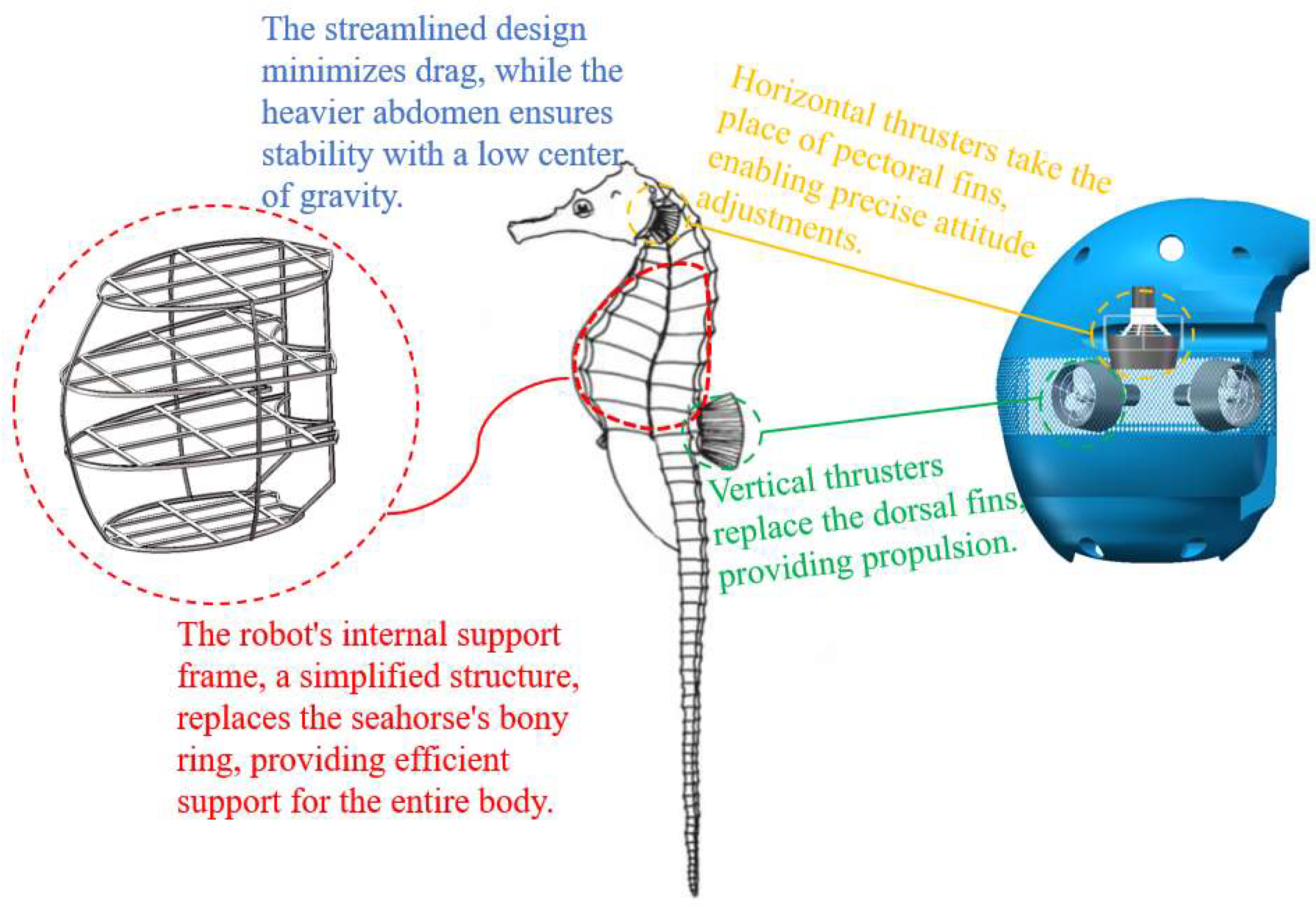
Considering the design requirements of lightweight construction, high stability, and modularity, seahorses were ultimately chosen as the bionic model for configuration. Unlike fast-swimming creatures, seahorses move vertically in the water, a capability supported by their unique anatomy. Their lack of a swim bladder and rigid bony plates limit their swimming speed but enable exceptional hovering ability. Seahorses maintain a stable vertical posture by swinging their dorsal fins and adjusting fin angles for propulsion, while their flexible tails bend to maintain balance. Their heavy abdomen provides a low center of gravity, enhancing stability, while their streamlined body minimizes water resistance and reduces posture disruption.
The preliminary design concept is illustrated in
Figure 3 [
27]. The high metacentric design ensures that the underwater vehicle maintains a predominantly vertical posture, mimicking the upright movement of a seahorse to enhance maneuverability and facilitate navigation through complex underwater environments. Horizontal and vertical propulsion devices replicate the seahorse’s dorsal fin vibrations and pectoral fin steering, providing thrust and enabling precise attitude adjustments. The rigid bony rings of the seahorse, which protect their internal organs and minimize drag, inspire the vehicle’s structural design. The internal configuration features a simplified support frame that stabilizes the entire body while accommodating equipment, ensuring ease of integration and transport.
The remainder of this paper is organized as follows:
Section 2 presents the scientific modeling of the streamlined configuration using specific mathematical equations and outlines the overall design and operational flow of the underwater robot. In
Section 3, computational fluid dynamics (CFD) simulations are used to evaluate static stability and dynamic stability. In
Section 4, an optimization function is developed to determine the optimal configuration and enhance the dynamic stability in the horizontal plane. Finally, a conclusion is provided based on the above research.
2. Configuration Design of an Underwater Inspection Vehicle for Dams
The above configuration is only a preliminary design, and it is necessary to realize the scientific modeling of the streamline configuration with specific mathematical equations.
2.1. Fundamental Theory
The B-spline method, originally proposed by Schoenberg and derived from the Bessel curve, retains the advantages of the Bessel curve while enabling localized modifications without altering the overall shape. This method allows for efficient curve or surface representation using fewer control points, making it one of the most widely used mathematical approaches today [
28,
29].
The expression of the B-spline curve of degree
k is as follows:
Non-uniform rational B-splines (NURBSs) are an important extension based on B-spline curves. The NURBS curve is defined as follows:
NURBS surfaces of degree
k in
u and degree
q in
v are two-parameter piecewise rational functions of the following form:
The NURBS interpolation algorithm constructs a NURBS curve by interpolating a set of arbitrary data, including data point coordinates and guiding vectors. This process ensures that the generated curve or surface strictly adheres to specified data constraints, passing through each data point and aligning with the designated guiding vectors at specific locations.
2.2. Design Procedure
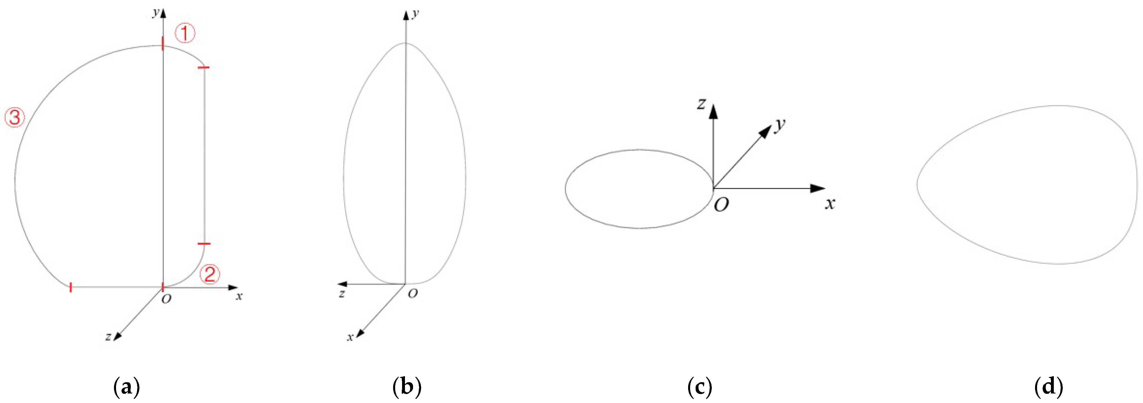
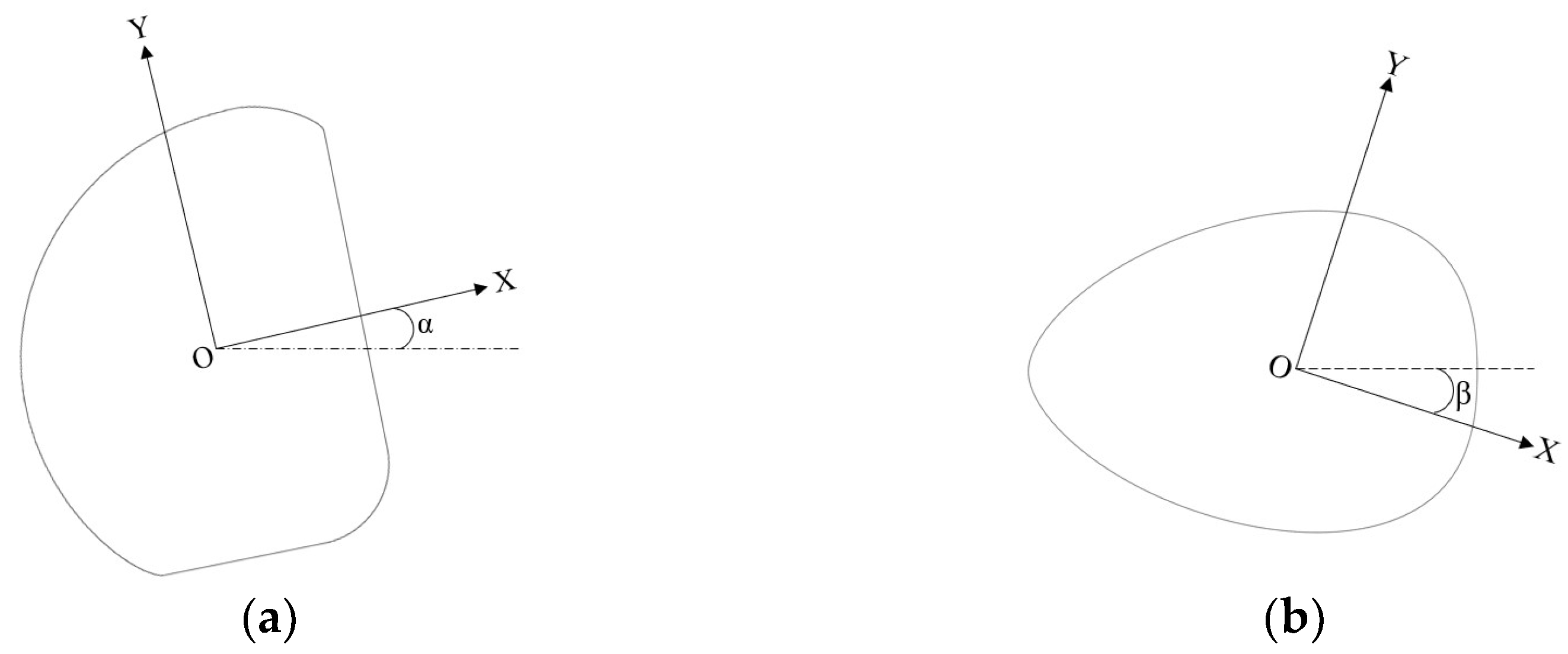
In this paper, the three-dimensional configuration of the non-rotating body is designed, with its contour lines represented mathematically in three principal directions: the transverse section, horizontal plane, and longitudinal section. Due to the lack of complete symmetry among these directions, the asymmetric surfaces are divided into multiple segments to construct the streamlined surface of the vehicle. The coordinate system for this streamlined configuration is illustrated in
Figure 4. The standard rectangular coordinate system O-xyz is employed, where the origin O is located at the right end of the bottom surface, and the
x,
y, and
z axes correspond to the forward, vertical, and lateral directions of the configuration, respectively.
The asymmetric section curve cannot be represented by a single mathematical equation, so it is designed in segments. As shown in
Figure 4a, the transverse section curve is composed of three curves (ellipse, circle, and NURBS) and two straight lines, with each segment defined parametrically. Only one-half of this symmetric curve is expressed, and the starting and ending tangents are perpendicular to the axis of symmetry. Except for the cross-section, other curves are symmetric. Irregular segments are represented by NURBS curves, which are generated through interpolation using specified data points and defined endpoints. According to the design requirements, these equations for various profile curves are used to construct the profile lines. Using NURBS surface functions and lofting techniques, a 3D model of the vehicle is created, as shown in
Figure 4.
2.3. Overall Design
Based on the design plan, the underwater vehicle measures 1.3 m in length, 0.9 m in width, and 1.5 m in height, with an approximate volume of 1 m
3 and a total weight of around 180 kg. The design incorporates micro-positive buoyancy, as illustrated in
Figure 5.
The vehicle is equipped with a self-disconnecting hanger device on its top, facilitating lifting and protecting the umbilical cable. To ensure underwater stability, the relative positioning of the center of buoyancy and the center of gravity must be carefully designed. Ideally, these centers should align vertically, with the center of buoyancy above the center of gravity, enhancing both static and dynamic stability. Because the underwater vehicle in this design is not fully sealed, buoyancy is provided by buoyant materials positioned primarily in the upper section, in line with the vehicle’s configuration to increase metacentric height. Stability is further improved by lowering the center of gravity, such as by adding weight to equipment at the bottom.
To handle various dam surfaces, the vehicle is equipped with optical imaging equipment, supported by a light-emitting diode (LED), and various acoustic devices. Communication equipment is installed on top to minimize interference. The vehicle arms are placed on each side of the optical equipment within the operational range, keeping the height as low as possible. Side-scan sonar units are mounted on either side of the vehicle. A sub-unit, located at the bottom for easy detachment and recovery, connects to the main vehicle via an umbilical cable, with the main unit having a small winch control. Emergency self-rescue equipment includes a jettison mechanism and buoys.
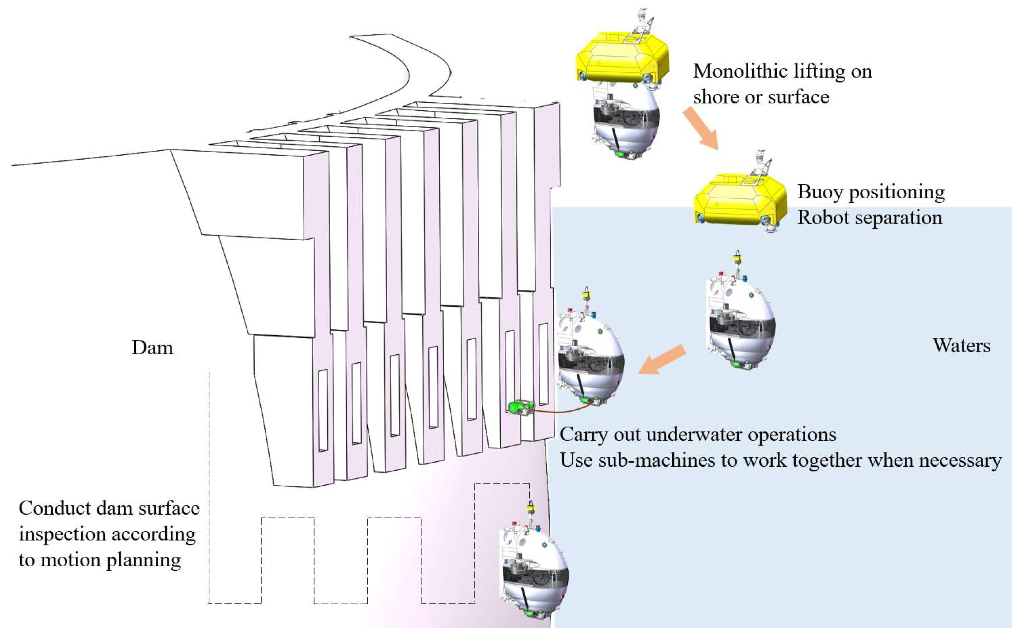
The vehicle operation process consists of deployment, diving, dam surface inspection, dredging, and recovery. As shown in
Figure 6, the power buoy and vehicle are initially deployed together. After disconnecting from the buoy, the vehicle descends to the target dam surface and begins the planned inspection route. If certain areas are inaccessible, the sub-unit is deployed for further investigation. In cases of sediment buildup, the vehicle performs dredging to clear the silt. Finally, the vehicle collaborates with the propulsion system and umbilical cable for recovery.
4. Optimization of Configuration
The vehicle configuration optimization process (
Figure 17) utilizes free deformation technology to modify the original design, establishing an optimization objective function. This process is divided into four steps: design, deformation, simulation, and optimization. CAESES software was used for free deformation, with the vehicle configuration deformation grid set to 1.5 m × 1 m × 1.8 m, divided into eight equal sections.
The deformation size corresponds to the change in control points, with the influence diminishing as the control points move away from the surface. Based on the grid distribution, two deformation operations were performed (
Figure 18,
Figure 19 and
Figure 20), as follows:
Control points along the vehicle’s working face in the x-direction were selected, and their longitudinal tilt angle was adjusted within a range of [−5°, 5°], with a step size of 1°.
The symmetry axis of the vehicle’s working face was selected, and its stretching parameters along the x-axis (forward direction) were modified within a range of [0.05 m, 0.25 m], with a step size of 0.05 m.
To optimize the vehicle’s performance, multiple configurations are generated through local deformation, and the one with the best overall performance is selected. The optimization is constrained by a drainage volume variation of ≤2%, with resistance and stability as the primary objectives. Due to the limited propeller power caused by the umbilical cable, the weight of resistance is relatively low, while the weight of stability is higher. The optimization function is defined as follows:
In these equations, and represent the drag forces of the deformed and original configurations, respectively, under the forward three-segment condition. and represent the drag forces of the deformed and original configurations, respectively, under the lateral two-segment condition. is the vertical plane static stability criterion, is the horizontal plane static stability criterion, is the vertical plane dynamic stability criterion, and is the horizontal plane dynamic stability criterion. and are the horizontal plane stability parameters for the deformed and original configurations, respectively. represents the volume of the deformed configuration, and represents the volume of the original configuration.
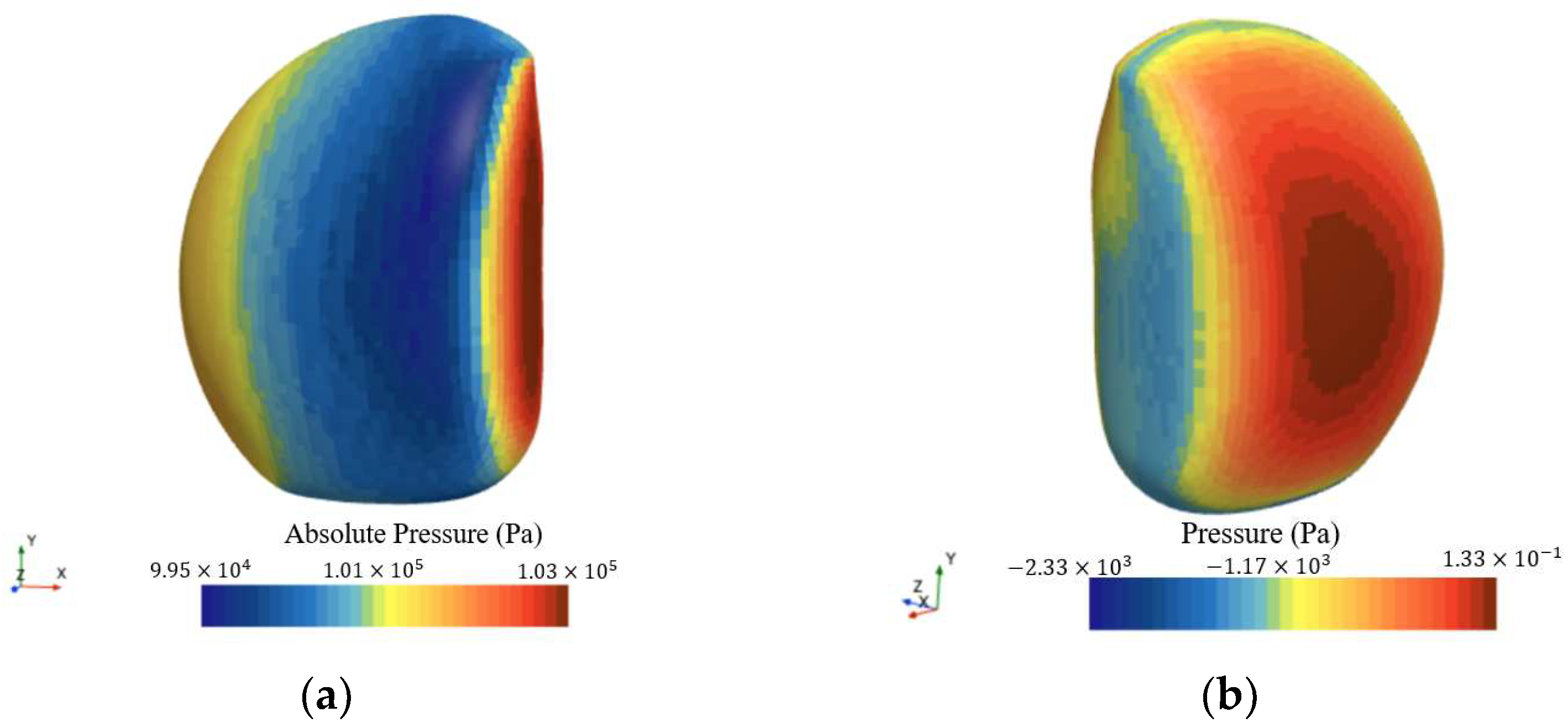
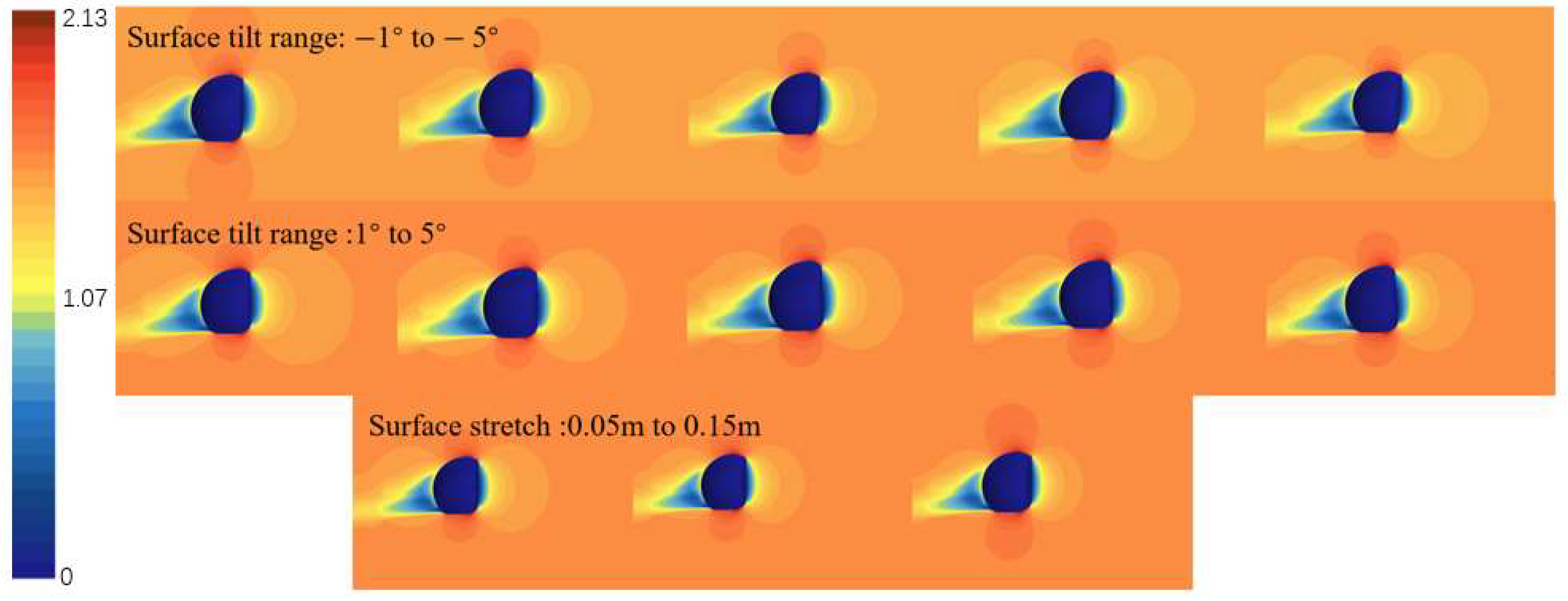
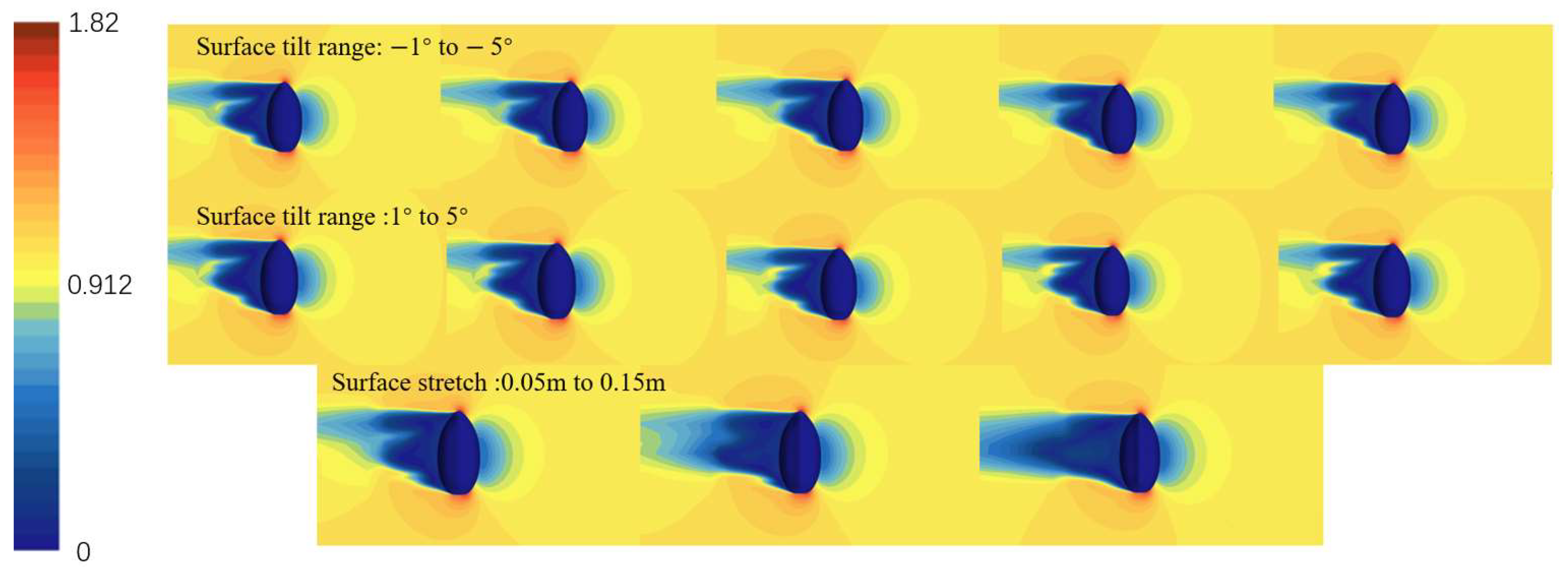
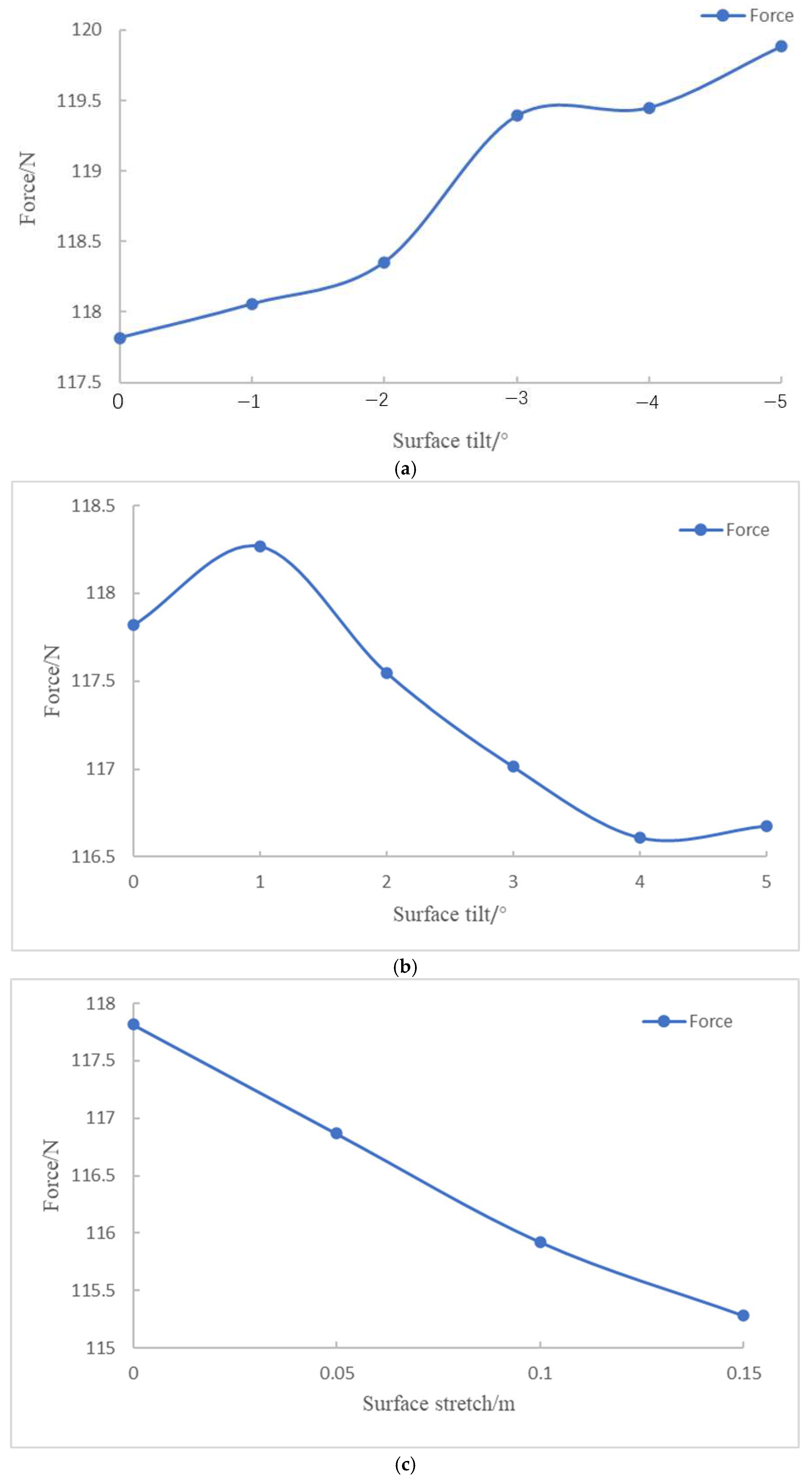
The deformation configurations of 0.20 m and 0.25 m do not satisfy the optimization constraints and are therefore excluded. To investigate the hydrodynamic behavior of the vehicle under forward three-knot and lateral two-knot inflows, velocity contour plots for various deformation configurations were generated through steady-state simulations. The results are presented in
Figure 21,
Figure 22,
Figure 23 and
Figure 24.
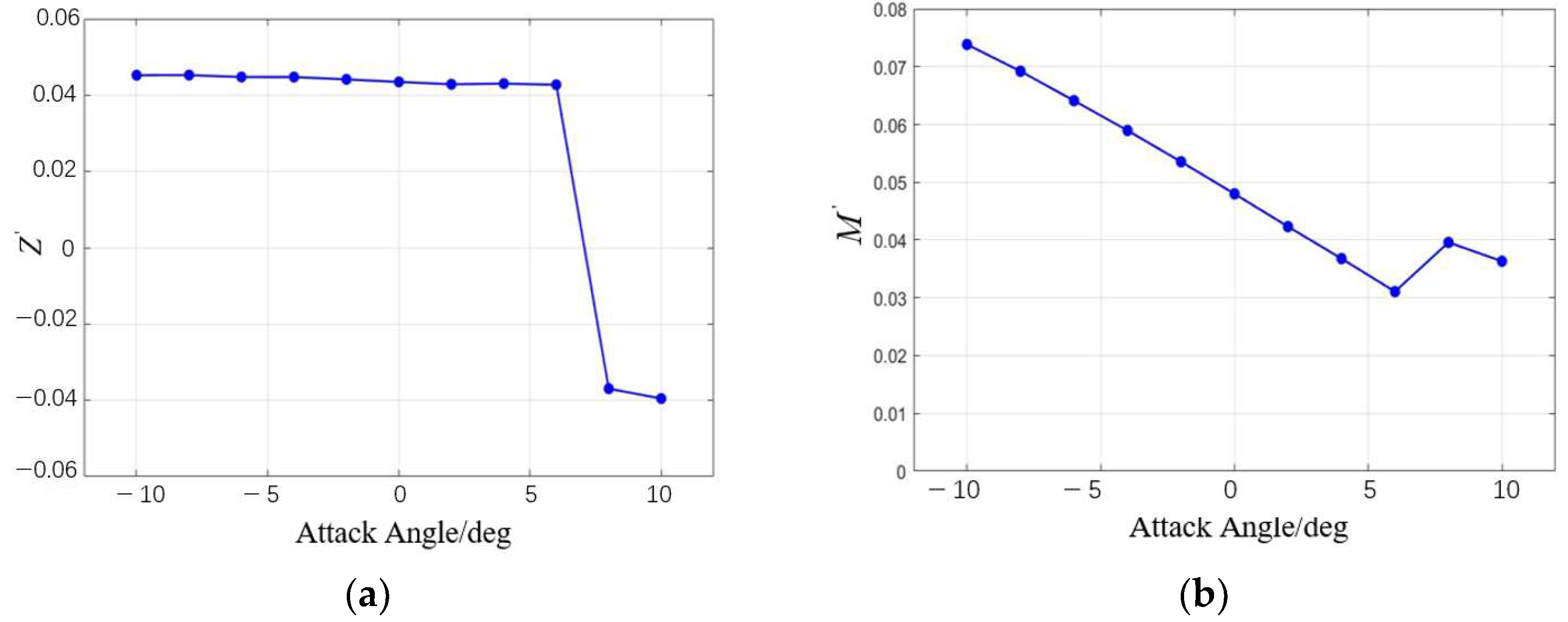
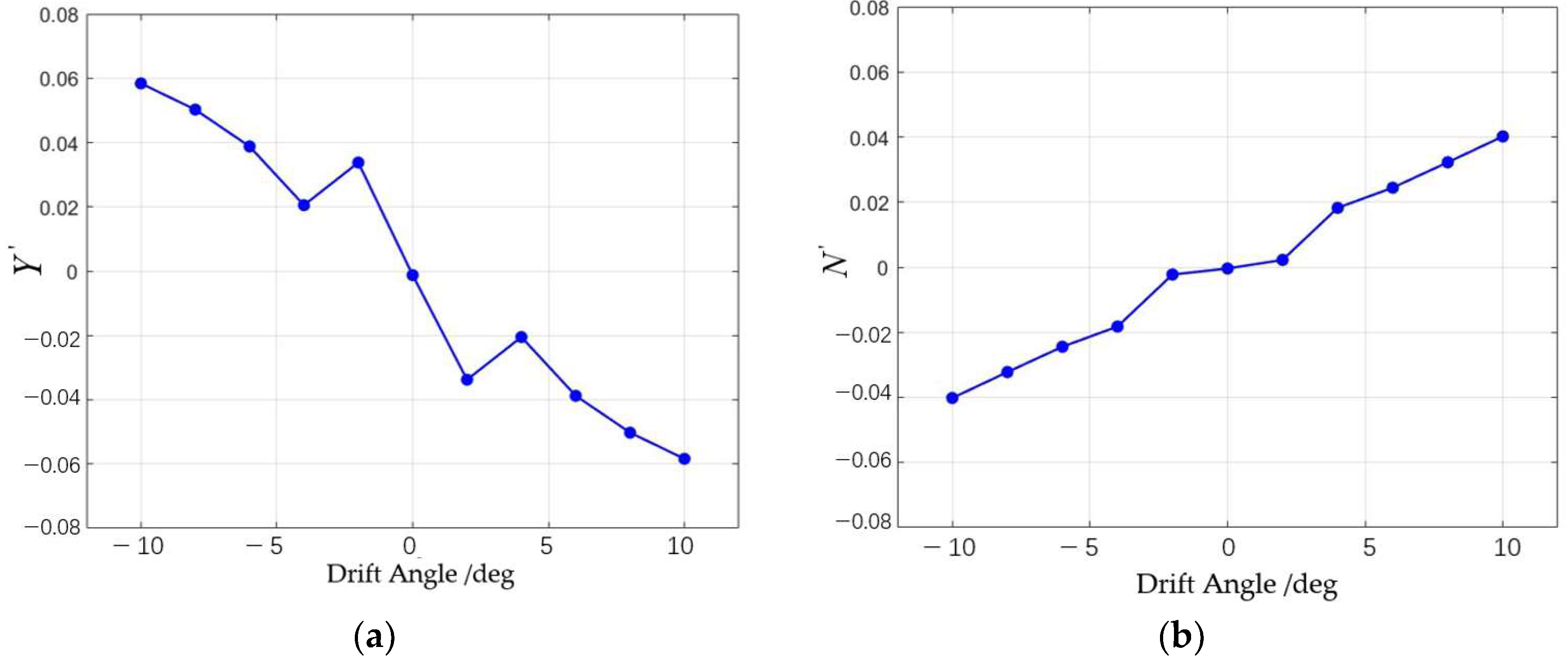
The static stability of the series configuration was evaluated through simulations involving variable angles of attack and drift. As shown in
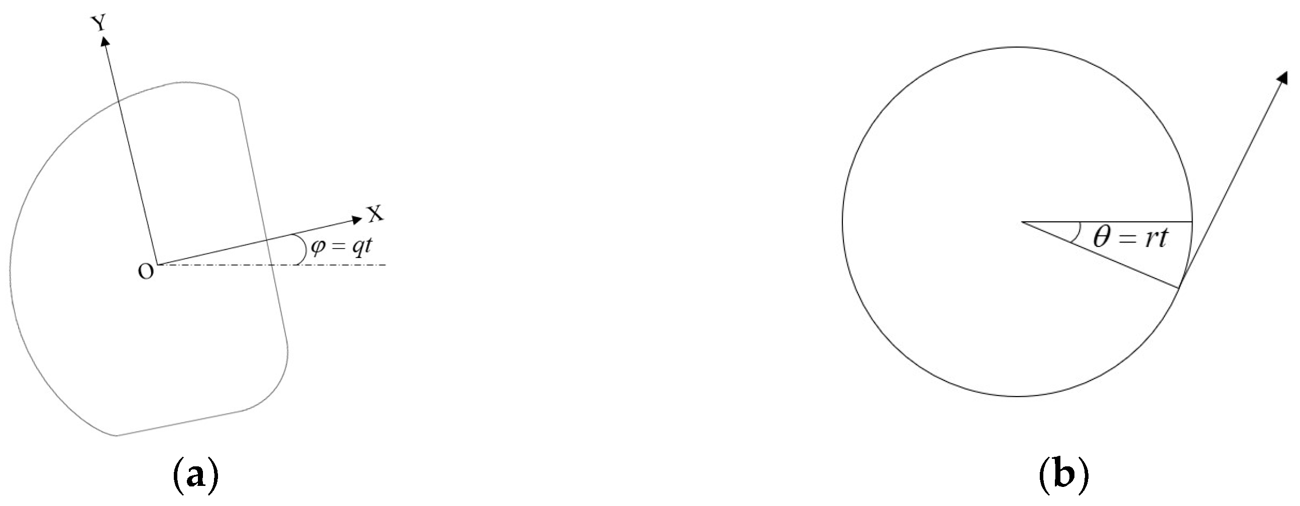
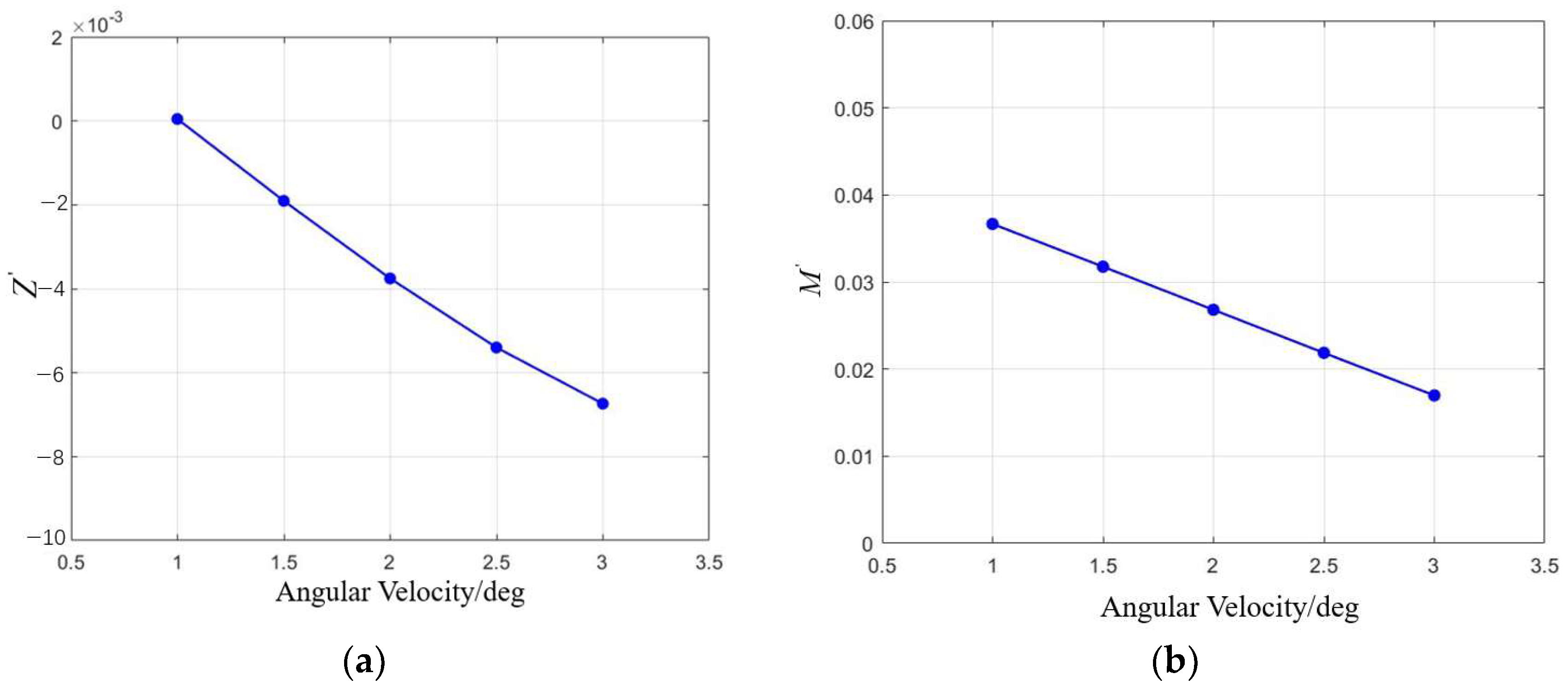
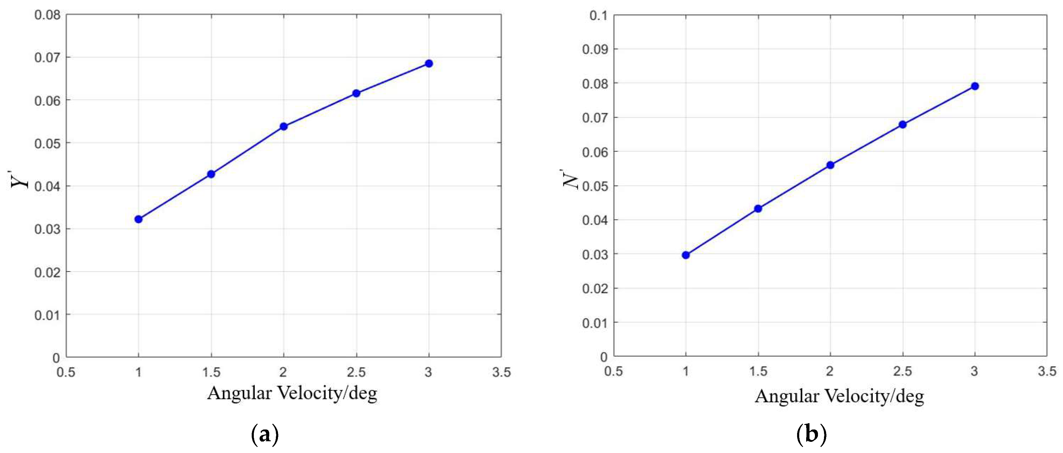
Table 7, the results indicate that changes in the tilt or stretch of the oncoming plane have minimal impact on the static stability of both the vertical and horizontal planes, with the configuration remaining stable within a tilt range of [−10°, 6°]. Increasing the bottom indentation and top outward expansion improves the horizontal static stability. Dynamic stability is then assessed through simulations of pitching and rotating motions. It is observed that variations in the oncoming surface significantly affect the dynamic stability in the horizontal plane. Specifically, the
CH coefficient decreases as the tilt angle increases, while it increases with the stretching of the oncoming surface. However, all configurations lack horizontal dynamic stability. The vertical dynamic stability remains largely unaffected by these changes, ensuring stability in the vertical plane.
As shown in
Table 8, the optimal configuration corresponds to a 0.15 m surface stretch deformation. Compared to the original design, this configuration results in a 2.15% reduction in forward resistance, a 21.62% increase in lateral resistance, and a 1.98% increase in volume. It exhibits good static stability and maintains vertical dynamic stability. While it lacks full horizontal dynamic stability, the horizontal stability improves from −2.805 to −1.815, indicating a notable enhancement in horizontal plane dynamic stability.
5. Conclusions
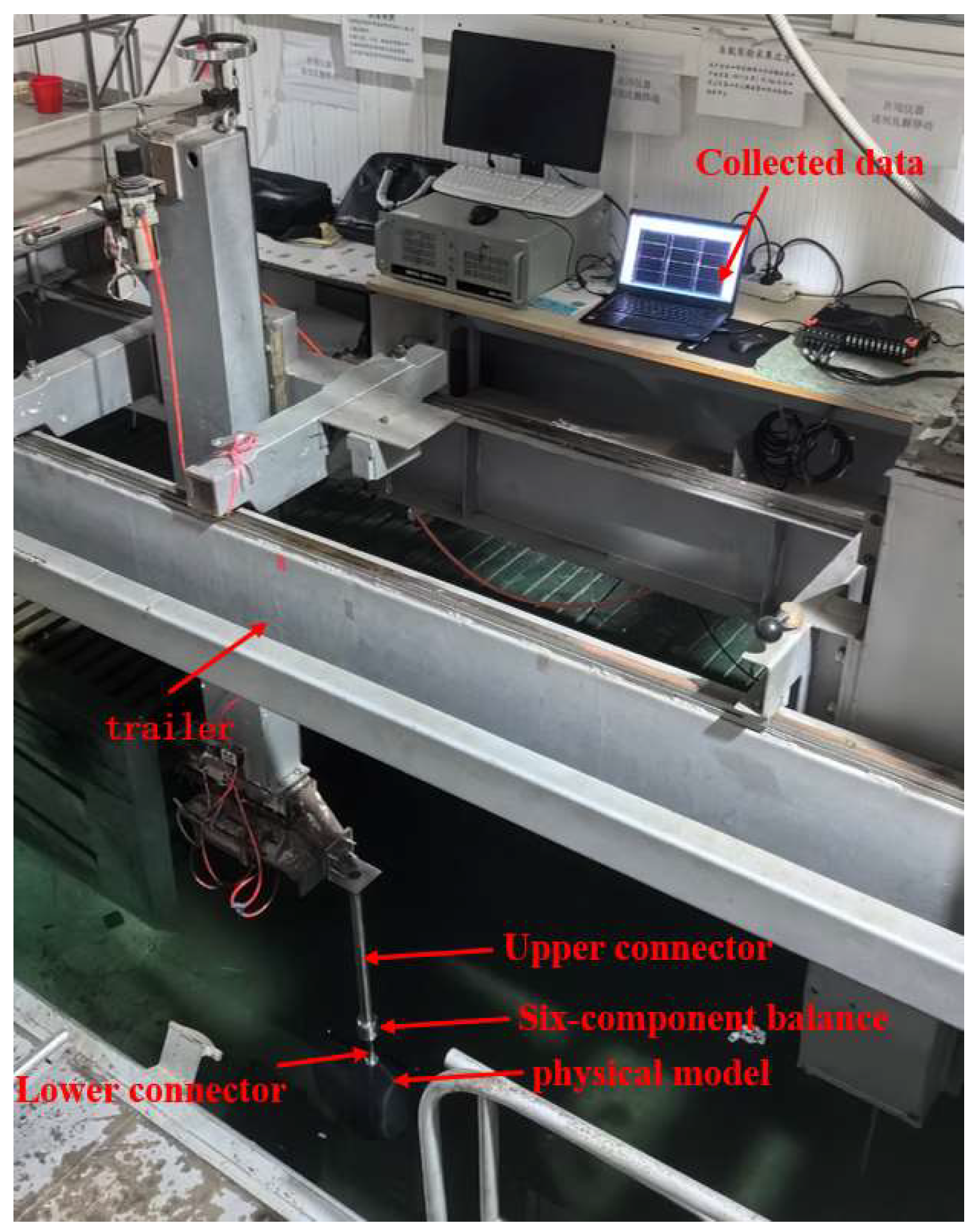
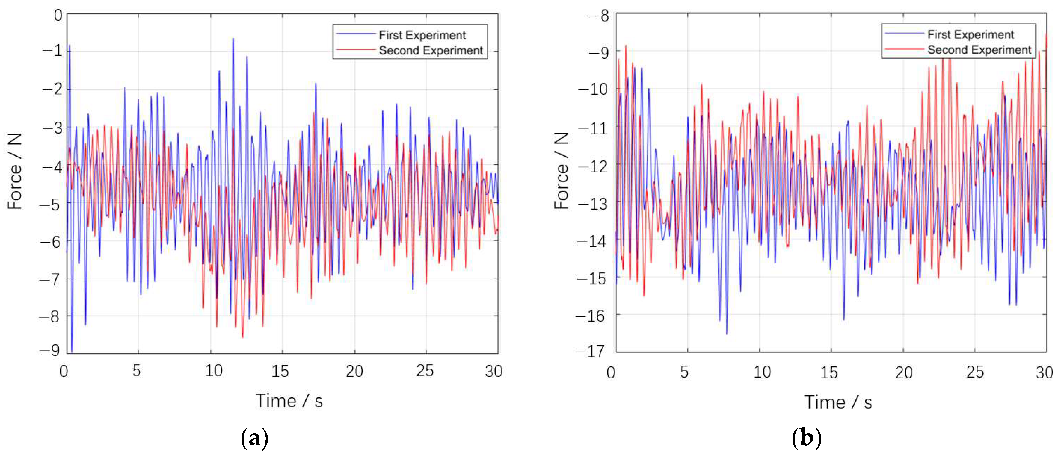
This paper addresses the demand for underwater dam defect detection by designing an overall layout and operational mode for a streamlined underwater robot and parameterizing the streamlined configuration. CFD methods were used to conduct a series of hydrodynamic simulations on the configuration, calculating relevant hydrodynamic coefficients and determining the stability of the configuration. A scaled physical model was built, and resistance data were collected through towing tests in a water tank. The full-scale drag was then calculated using a drag conversion formula, and the reliability of the CFD method was verified through comparison. A series of different configurations were generated using the free deformation method, and hydrodynamic simulations were performed for each. The drag and stability performance were used to establish an optimization objective function, which was optimized using a genetic algorithm. The main research findings of this paper are as follows:
1. In response to the specific requirements of underwater dam defect detection, a streamlined configuration inspired by the shape of a seahorse was designed, integrating the vehicle’s hydrodynamic performance and operational posture. This bionic design is particularly significant for the development of the ROV hover system.
2. A streamline model of the vehicle was developed to assess its hydrodynamic coefficients under various working conditions. The evaluation results show that, while the vehicle lacks horizontal dynamic stability, it maintains static stability in both the horizontal and vertical planes, as well as dynamic stability in the vertical plane.
3. The vehicle’s original configuration was optimized using free deformation technology. The optimization function, focused on resistance and stability, with a volume change constraint of ≤2%, was established. The optimized configuration resulted in a 2.152% reduction in forward resistance and a 35.29% improvement in horizontal dynamic stability (CH).


