Article

Adaptive Positioning Control of Multi-Point Moorings with Disturbance Observation Under Input Constraints

1
Merchant Marine College, Shanghai Maritime University, Shanghai 201306, China
2
Shanghai Marine Equipment Research Institute Co., Ltd., Shanghai 201306, China
*
Author to whom correspondence should be addressed.
J. Mar. Sci. Eng. 2025, 13(1), 30; https://doi.org/10.3390/jmse13010030
Submission received: 15 December 2024 / Revised: 23 December 2024 / Accepted: 27 December 2024 / Published: 29 December 2024
(This article belongs to the Section Ocean Engineering)

Abstract

:
In the presence of dynamic uncertainties, external time-varying disturbances, and limited inputs to the multi-point mooring system (MPMS) of a floating offshore platform (FOP), this paper proposes a robust adaptive dynamic surface (RADS) control method incorporating a disturbance observer. A disturbance observer is designed to estimate the unknown time-varying disturbance and apply feedforward compensation to the control variable. Simultaneously, the adaptive law of the σ-corrected leakage term is employed to estimate the bound of the disturbance observation error, thereby enhancing positioning accuracy. An auxiliary dynamic system (ADS) is then introduced to address input constraints, while the differential explosion problem associated with the traditional inversion method is resolved through the integration of the dynamic surface control (DSC) algorithm. The Lyapunov function is utilized to demonstrate that the controller ensures the consistent ultimate boundedness of all signals within the closed-loop system. Finally, a simulation experiment was conducted based on the eight-point mooring platform of the “Kantan3”, and the positioning accuracy reached 3%, which is higher than the specification requirements of the classification society. The results indicate that the designed controller achieves higher positioning accuracy and improved anti-interference performance and has been put into practical application on “Kantan3”.

1. Introduction

With the increasing depletion of onshore resources, the development and utilization of marine oil and gas energy has become an important development trend. Floating offshore platforms (FOPs) are increasingly important in the development of offshore oil and gas resources. Therefore, the design of platform positioning systems is particularly important. The positioning modes of FOP include multi-point mooring system (MPMS) [1], dynamic positioning (DP) [2], and combined positioning mode [3]. Among them, the combined positioning mode has the best performance but is very expensive [4]. MPMS has the characteristics of low investment, easy maintenance, and good adaptability to the marine environment and is widely used in FOP and barges in offshore waters [5]. This type of ship is generally a non-powered, non-self-propelled ship and mainly relies on the mooring system to resist external environmental disturbances to suppress platform deflection to achieve mooring and positioning [6].
MPMS is a nonlinear dynamic problem, so its design is complex [7]. Kim et al. [8] and Nguyen et al. [9] modeled the system consisting of barge and mooring cables and adopted a PID control strategy to control the position and direction of the ship by changing the tension of the mooring cables. Zhang et al. [10] established the MPMS forward and inverse solution models and determined the relationship between the MPMS position and the anchor Chain Ji et al. [11,12] designed an H -based robust control system for the ship mooring control allocation problem, which simultaneously carried out controller design and control allocation and uniformly handled system stability and control performance. Zhou et al. [13] conducted a comparative study on the control design of single-point mooring and multi-point mooring and showed that reconfiguring the length of the catenary mooring can effectively suppress the platform pitch motion. Su et al. [14] proposed an automatic mooring positioning scheme with the goal of uniform tension distribution and designed a cost-guaranteed control method for the mooring automatic positioning system considering input delay. Considering the unpredictability of marine environmental disturbances, control parameters must be adaptively modified to ensure optimal performance. Zhang et al. [15] used a convolutional neural network (CNN) to extract fault features and DRNN to learn the dynamic change characteristics of MPMS to optimize KP, KI, and KD and proposed an online self-learning PID based on DRNN in MPMS. Shin et al. [16] used a fuzzy logic controller (FLC) to dynamically adjust control parameters so that it could effectively adapt to rapidly changing ocean conditions. Wang et al. [17] used backstepping and integrated non-singular fast terminal sliding mode surface (INFTSMS) to suppress chattering and proposed an adaptive estimator to deal with unknown system uncertainties and external environmental interference. Zhang et al. [18] combined a set value tracking algorithm based on structural reliability with an adaptive fuzzy estimator to derive an improved DSC law, which improved the convergence speed of the filtering error. Mao et al. [19] used a deep neural network (DNN) method to predict the dynamic anchor chain tension in the event of anchor chain failure and verified that the significant increase in surge and sway motion caused by mooring breakage is the main controlling variable for mooring tension prediction. Failure or breakage of the mooring chain can cause the moored platform to drift severely or even stop operating [20]. Simultaneously, for safety reasons, an excessively large change rate of the combined force of the MPMS can cause the anchor machine to jump in speed, posing a great challenge to the safety of the mooring cable. Although considering the limited input of the mooring system will greatly increase the difficulty of designing the control system, it is more in line with the actual application scenario.
The application of adaptive robust controllers in multiple fields such as hypersonic vehicle control [21], nonlinear system adaptive control [22], and medical robot control [23] has demonstrated the importance and effectiveness of adaptive robust control methods in dealing with uncertainties and improving system robustness. So as to solve the above problems, this paper designs a robust adaptive dynamic surface (RADS) positioning control method with disturbance observer by combining disturbance observer, ADS and DSC under the condition of external time-varying disturbance and input constraint. This method constructs a disturbance observer to estimate the external environmental disturbance and uses its feedforward control to compensate for the control quantity, effectively weakening the chattering. Considering the existence of disturbance observation error, the adaptive law of the σ-corrected leakage term is used to estimate it and improve the control accuracy. An ADS is introduced to deal with input constraints, and the DSC technology is combined to avoid computational expansion. The Lyapunov function is selected to prove that the control law can ensure the consistent ultimate boundedness of all signals in the closed-loop system. Classification societies stipulate that the positioning error of MPMS is ≤3~5% of the water depth, and the pitch and heel angles are ≤1°. The proposed MPMS RADS positioning control method is applied to the “Kantan3” eight-point mooring platform to verify the effectiveness of the designed controller.

2. Problem Formulation and Preliminaries

As shown in Figure 1, OOXOYOZO is an inertial coordinate frame fixed on the surface of the earth, with its origin taken at any point on the ground or sea surface. The OOXO axis points to the initial motion direction of the platform in the static horizontal plane. The OOYO axis and the OOXO axis are in the same plane and perpendicular to the OOXO axis. The OOZO axis is perpendicular to the static water surface and points to the center of the earth in the positive direction, which conforms to the right-hand rule. The platform’s motion coordinate frame OXYZ has its origin taken at the center of mass of the platform. The OX axis is along the longitudinal axis of the platform and points to the bow. The OY axis is consistent with the pitch axis and points to the starboard side. The OZ axis points to the bottom of the platform.
The FOP moves at a low speed during operation, and its motion on the sea level is mainly studied. Therefore, the low-frequency motion model of FOP surge, sway, and yaw is established as follows [24]:
η ˙ = R ψ ν M v ˙ + D v = τ + w ( t )
where, η = [x, y, ψ]T is the position vector of the platform in the earth-fixed coordinate frame, which consists of the platform’s surge position x, the sway position y, and the yaw angle ψ. ν = [u, υ, r]T is the velocity vector of the platform in the body-fixed coordinate frame, which is composed of the platform’s surge velocity u, sway velocity υ, and yaw rate r. R(ψ) is the rotation matrix given by the following:
R ψ = cos ψ sin ψ 0 sin ψ cos ψ 0 0 0 1
M is the inertia matrix including the additional mass, D is the damping matrix including the mooring cable damping, and τ = [ τ 1 , τ 2 , τ 3 ] T is the resultant force and moment vector that the mooring system can provide. In addition, due to the physical characteristics of the FOP mooring system, the force that the mooring system provides cannot be infinite, and for safety reasons, excessive changes in the anchor cable tension should be avoided and the following saturation limits should be met:
τ i = τ i max , i f τ c i > τ i max τ c i , i f τ i min < τ c i < τ i max τ i min , i f   τ c i < τ i min i = 1 , 2 , 3
where, i = 1, 2, and 3 represent platform surge, sway, and yaw, respectively; τ c i represent the desired control input calculated by the controller at the i-th degree of freedom; τ i max and τ i min represent the maximum or minimum resultant force and moment that the mooring system can provide in the i-th degree of freedom, respectively, and Δ τ = τ τ c is the difference between the actual control signal and the command control signal. w ( t ) = [ w 1 ( t ) , w 2 ( t ) , w 3 ( t ) ] T is the external environmental disturbance vector.
Assumption 1. 
The external disturbance wi(t), where i = 1, 2, and 3, are unknown time-varying yet bounded, and the rate change in the disturbance is bounded, such that, w ˙ ( t ) ρ .
From Equation (3), it can be seen that the saturation limit has no effect when the expected control input is within the saturation limit; when the expected control input exceeds the saturation range, the saturation limit will cause the actual control force to deviate from the expectation, thereby causing the system control performance fall. Therefore, in the design process, this paper introduces an ADS, designs a RADS controller, and introduces a tension distribution algorithm to realize a multi-point mooring automatic positioning system in response to the situation where the mooring system input is limited. The positioning principle of the MPMS is shown in Figure 2. The RADS controller calculates the resultant force and torque required for the FOP to maintain the desired position under the current disturbance and distributes the control resultant force to the eight mooring cables through the tension distribution algorithm. The anchor winch controls the mooring cables to reach the distribution value, thereby moving or maintaining the FOP at the desired position. This control method can not only ensure the positioning accuracy of the FOP but also ensure that the tension of the mooring cable changes relatively smoothly during the control process while taking into account the uniform distribution of the mooring cable tension to avoid the breakage of the mooring cable caused by excessive tension.

3. Control Design and Analysis

3.1. Nonlinear Disturbance Observer Design

First, a nonlinear disturbance observer is designed to estimate the external unknown time-varying disturbance. The design of the disturbance observer is as follows:
w ^ ( t ) = z ( t ) + K 0 M ν
z ˙ ( t ) = - K 0 z ( t ) K 0 [ D ν + τ + K 0 M ν ]
where w ^ ( t ) R 3 is an estimated value of w(t), z ( t ) R 3 is the auxiliary state vector, and K 0 = K 0 T R 3 × 3 is the positive definite design matrix to be designed.
The estimated error vector of the observer is defined as follows:
w ˜ = w w ^
From Equations (4), (5), and (1), we have the following:
w ^ ˙ = z ˙ ( t ) + K 0 M ν ˙ = K 0 w ˜
According to Equations (6) and (7), we can get the following:
w ˜ ˙ = w ˙ w ^ ˙ = w ˙ K 0 w ˜

3.2. RADS Controller Design

Using disturbance observer and adaptive dynamic surface algorithm, a robust nonlinear control law for MPMS of FOP is designed, in which an ADS is used to solve the input constraint problem. The whole design includes the following two steps:
Step 1: Define the position error vector S 1 R 3 as follows:
S 1 = η η d
According to Equation (1), the time derivative of Equation (9) is as follows:
S ˙ 1 = R ( ψ ) ν
where ν is regarded as a virtual control vector.
Design the middle control vector α 1 R 3 for ν as follows:
α 1 = R 1 ( ψ ) K 1 S 1
where, K 1 = K 1 T R 3 × 3 is a positive definite design matrix.
Introduce a first-order low-pass filter.
T d χ ˙ d + χ d = α 1 χ d ( 0 ) = α 1 ( 0 )
where χ d R 3 is the state vector of the first-order filter and T d is the design constant.
Define the system filter error vector β R 3 .
β = χ d α 1
Step 2: Define the velocity error vector S 2 R 3 as follows:
S 2 = ν χ d
From Equations (14), (12), and (1), we have the following:
M S ˙ 2 = D ν + τ + w M χ ˙ d
To reduce the impact of Δ τ on the mooring positioning control performance, the following dynamic auxiliary system is constructed:
M ξ ˙ = K ξ ξ + Δ τ
where ξ is the state vector of the ADS, and K ξ R 3 × 3 is the positive definite symmetric matrix to be designed.
During the design process of the disturbance observer, problems such as inappropriate parameter selection may occur. The observer output will have a certain observation error, and its limit value is unknown. The sign function used in traditional sliding mode control is prone to cause control quantity chattering and damage system equipment. Therefore, this paper uses the parameter adaptation law with the σ-corrected leakage term to estimate the bound of the disturbance observation error and combines it with the hyperbolic tangent function to further weaken the chattering and improve the control accuracy. The RADS control law for MPMS is designed as follows:
τ c = D ν + M α 1 χ d T d + K ξ ξ K 2 S 2 Γ ( S 2 ) δ ^ w ^
where Γ ( S 2 ) = d i a g tanh ( S 2 , 1 / ε 1 ) , tanh ( S 2 , 2 / ε 2 ) , tanh ( S 2 , 3 / ε 3 ) R 3 × 3 , δ ^ = [ δ ^ 1 , δ ^ 2 , δ ^ 3 ] T R 3 is the upper bound estimation vector of the disturbance observer error w ˜ , and its adaptive law is designed as follows:
δ ^ ˙ = Π [ Γ ( S 2 ) S 2 Θ ( δ ^ δ 0 ) ]
where, Π = d i a g γ 1 , γ 2 , γ 3 , Θ = d i a g σ 1 ,   σ 2 ,   σ 3 are the positive definite parameter diagonal matrices of the design, γ i is the design parameter, σ i is chosen to be very small, but it is necessary to keep δ ^ from growing to unbounded; δ 0 = [ δ 1 0 , δ 2 0 , δ 3 0 ] T R 3 is the prior estimate of δ ^ i ( i = 1 , 2 , 3 ) .

3.3. Stability Analysis

The Lyapunov function is constructed as follows:
V = 1 / 2 S 1 T S 1 + 1 / 2 S 2 T M S 2 + 1 / 2 β T β + 1 / 2 δ ˜ T Π 1 δ ˜ + 1 / 2 ξ T M ξ + 1 / 2 w ˜ T w ˜
where, δ ˜ = δ ^ δ is the estimation error vector. According to Equation (19), we have the following:
V ˙ = S 1 T S ˙ 1 + S 2 T M S ˙ 2 + β T β ˙ + δ ˜ T Π 1 δ ^ ˙ + ξ T M ξ ˙ + w ˜ T w ˜ ˙
According to Equations (10), (11), (13), and (14), rotation matrix Properties R ( ψ ) = 1 and Young’s inequality, we can get the following:
S 1 T S ˙ 1 = S 1 T R ( ψ ) ( S 2 + χ d ) = S 1 T K 1 S 1 + S 1 T R ( ψ ) ( S 2 + β ) S 1 T K 1 S 1 + S 1 T S 1 + 1 / 2 S 2 T S 2 + 1 / 2 β T β
According to Equations (15)–(17) and Young’s inequality, we have the following:
S 2 T M S ˙ 2 = S 2 T ( K ξ ξ K 2 S 2 Γ ( S 2 ) δ ^ + w ˜ + Δ τ ) = S 2 T K 2 S 2 + S 2 T K ξ ξ S 2 T Γ ( S 2 ) δ ^ + S 2 T w ˜ + S 2 T Δ τ S 2 T K 2 S 2 S 2 T Γ ( S 2 ) δ ^ + S 2 T S 2 + 1 / 2 ξ T K ξ T K ξ ξ + S 2 T w ˜ + 1 / 2 Δ τ 2
From Equations (11)–(13), we have the following:
β ˙ = β / T d + R 1 ( ψ ) K 1 S ˙ 1 + R ˙ 1 ( ψ ) K 1 S 1   = β / T d + R 1 ( ψ ) K 1 R ( ψ ) ( S 2 + χ d ) + R ˙ 1 ( ψ ) K 1 S 1   = β / T d + R 1 ( ψ ) K 1 R ( ψ ) ( S 2 + β R 1 ( ψ ) K 1 S 1 ) + R ˙ 1 ( ψ ) K 1 S 1   = β / T d + Ξ ( S 1 , S 2 , β )
where Ξ ( S 1 , S 2 , β ) = R ˙ 1 ( ψ ) K 1 S 1 + R 1 ( ψ ) K 1 R ( ψ ) ( S 2 + β R 1 ( ψ ) K 1 S 1 ) is a continuous vector function.
In view of Equation (23) and Young’s inequality, we have the following:
β T β ˙ β T β / T d + β Ξ ( S 1 , S 2 , β ) β T β / T d + 1 / 2 β 2 Ξ ( S 1 , S 2 , β ) 2 + 1 / 2
From Equation (18) and Young’s inequality, we have the following:
δ ˜ T Π 1 δ ^ ˙ = S 2 T Γ ( S 2 ) δ ˜ ( δ ^ δ ) T Θ ( δ ^ δ 0 ) = S 2 T Γ ( S 2 ) δ ˜ 1 / 2 δ ˜ T Θ δ ˜ 1 / 2 ( δ ^ δ ) T Θ ( δ ^ δ ) + 1 / 2 ( δ δ 0 ) T Θ ( δ δ 0 )   S 2 T Γ ( S 2 ) δ ˜ 1 / 2 δ ˜ T Θ δ ˜ + 1 / 2 ( δ δ 0 ) T Θ ( δ δ 0 )
In the light of Equation (16) and Young’s inequality, we have the following:
ξ T M ξ ˙ = ξ T ( K ξ ξ + Δ τ ) ξ T K ξ ξ + 1 / 2 ξ T ξ + 1 / 2 Δ τ 2
According to Equation (8) and Young’s inequality, we have the following:
w ˜ T w ˜ ˙ = w ˜ T ( w ˙ K 0 w ˜ )   w ˜ T K 0 w ˜ + 1 / 2 w ˜ T w ˜ + 1 / 2 ρ 2
Substituting Equations (21), (22), (24)–(27) into Equations (20) yields the following:
V ˙ S 1 T K 1 S 1 + S 1 T S 1 + 1 / 2 S 2 T S 2 + 1 / 2 β T β S 2 T K 2 S 2 S 2 T Γ ( S 2 ) δ ^ + S 2 T S 2 + 1 / 2 ξ T K ξ T K ξ ξ + S 2 T w ˜ + 1 / 2 β T β / T d + 1 / 2 β 2 Ξ ( S 1 , S 2 , β ) 2 + S 2 T Γ ( S 2 ) δ ˜ 1 / 2 δ ˜ T Θ δ ˜ + 1 / 2 ( δ δ 0 ) T Θ ( δ δ 0 ) ξ T K ξ ξ + 1 / 2 ξ T ξ + Δ τ 2 w ˜ T K 0 w ˜ + 1 / 2 w ˜ T w ˜ + 1 / 2 ρ 2 [ λ min ( K 1 ) 1 ] S 1 T S 1 [ λ min ( K 2 ) 3 / 2 ] S 2 T S 2 [ 1 / T d 1 / 2 ] β T β 1 / 2 λ min ( Θ Π ) δ ˜ T Π 1 δ ˜ [ λ min ( K ξ 1 / 2 K ξ T K ξ ) 1 / 2 ] ξ T ξ [ λ min ( K 0 ) 1 / 2 ] w ˜ T w ˜ + 1 / 2 ρ 2 + 1 / 2 + Δ τ 2 + S 2 T w ˜ S 2 T Γ ( S 2 ) δ + 1 / 2 ( δ δ 0 ) T Θ ( δ δ 0 ) + 1 / 2 β 2 Ξ ( S 1 , S 2 , β ) 2
Considering the properties of the hyperbolic tangent function, for ε > 0 , a R , 0 a a tanh ( a / ε ) 0.2785 ε holds, and inequality S 2 i w ˜ i S 2 i w ˜ S 2 i δ i holds, then
S 2 T w ˜ S 2 T Γ ( S 2 ) δ 0.2785 P T δ
where P = [ ε 1 , ε 2 , ε 3 ] T .
Considering a compact set Ω = ( S 1 , S 2 , β , ξ , w ˜ ) : V B 0 , B 0 > 0 R 15 . Then, the two-norm Ξ ( S 1 , S 2 , β ) of the continuous vector function Ξ ( S 1 , S 2 , β ) has the maximum B M on Ω . Choosing 1 / T d = 1 / 2 + B M 2 / 2 + μ * ( μ * > 0 ) , we have the following:
V ˙ [ λ min ( K 1 ) 1 ] S 1 T S 1 [ λ min ( K 2 ) 3 / 2 ] S 2 T S 2 + 1 / 2 β T β ( 1 / 2 + B M 2 / 2 + μ * ) β T β 1 / 2 λ min ( Θ Π ) δ ˜ T Π 1 δ ˜ [ λ min ( K ξ 1 / 2 K ξ T K ξ ) 1 / 2 ] ξ T ξ [ λ min ( K 0 ) 1 / 2 ] w ˜ T w ˜ + 1 / 2 ρ 2 + 1 / 2 + Δ τ 2 + 0.2785 P T δ + 1 / 2 ( δ δ 0 ) T Θ ( δ δ 0 ) + Ξ ( S 1 , S 2 , β ) 2 B M 2 B M 2 β 2 2 2 μ V + C ( 1 Ξ ( S 1 , S 2 , β ) 2 / B M 2 ) B M 2 β 2 / 2
where
μ = min ( γ S 1 , γ S 2 , γ β , γ δ ˜ , γ ξ ˜ , γ w ) > 0
C = 1 / 2 + 1 / 2 ρ 2 + Δ τ 2 + 0.2785 P T δ + 1 / 2 ( δ δ 0 ) T Θ ( δ δ 0 )
γ S 1 = [ λ min ( K 1 ) 1 ] , γ S 2 = [ λ min ( K 2 ) 3 / 2 ] / λ max M , γ β = μ * , γ δ ˜ = λ min ( Θ Π ) , γ ξ ˜ = [ λ min ( K ξ 1 / 2 K ξ T K ξ ) 1 / 2 ] , γ w ˜ = [ λ min ( K 0 ) 1 / 2 ] , λ min ( ) is the minimum eigenvalue of the matrix, λ max ( ) is the maximum eigenvalue of the matrix. The design parameters ε , K 0 , K 1 , K 2 , K ξ , T d , Θ , and Π meet the following requirements:
λ min ( K 1 ) > 1 λ min ( K 2 ) > 3 / 2 λ min ( Θ Π ) > 0 λ min ( K ξ 1 / 2 K ξ T K ξ ) > 1 / 2 λ min ( K 0 ) > 1 / 2 1 / T d = 1 / 2 + B M 2 / 2 + μ * μ > C / 2 B 0
when V ( S 1 , S 2 , β , ξ , w ˜ ) = B 0 , there exists Ξ ( S 1 , S 2 , β ) B M , then V ˙ 2 μ B 0 + C from Equation (30). As such, it follows that V ˙ < 0 on V ( S 1 , S 2 , β , ξ , w ˜ ) = B 0 due to Equation (33). Therefore, Ω = ( S 1 , S 2 , β , ξ , w ˜ ) : V B 0 is an invariant set, i.e., if V B 0 , then V ( t ) B 0 for all t > 0 . Thus, Ξ ( S 1 , S 2 , β ) B M holds for all V ( 0 ) B 0 , and then
V ˙ 2 μ V + C
holds for all V ( 0 ) B 0 from Equation (30).
Based on the above theoretical analysis, the theorem is summarized as follows:
Theorem 1. 
Consider the closed-loop system consisting of the FOP(1) with dynamic uncertainties, external time-varying disturbances, and mooring tension input constraints under Assumption 1 and the MPMS RADS control law (17). For all V ( 0 ) B 0  with B0 being any positive constant, the position error surface vector S 1 = η η d  falls within the range of Ω S 1 = S 1 R 3 | S 1 ζ S 1 , ζ S 1 > C / μ  and can be made arbitrarily small by appropriately adjusting the design parameters ε K 0 K 1 K 2 K ξ T d Θ , and Π  to satisfy Equation (33) while ensuring that all signals of the MPMS control system are consistent and bounded.
Proof. 
Solve Equation (34), we can get the following:
0 V ( t ) C 2 μ + [ V ( 0 ) C 2 μ ] e 2 μ t
Obviously, for all V ( 0 ) B 0 , V(t) is ultimately bounded. Therefore, according to Equation (19), for all V ( 0 ) B 0 , S 1 , S 2 , β , ξ and w ˜ are ultimately bounded. Furthermore, from Equations (6), (9), (11), (13), and (14) and the boundedness of w, it can be seen that for all V ( 0 ) B 0 , η, α 1 , χ d , ν and ŵ are ultimately bounded. Therefore, for all V ( 0 ) B 0 , all signals of the MPMS control system are consistent and bounded.
According to Equations (19) and (35), we have the following:
0 S 1 C μ + 2 [ V ( 0 ) C 2 μ ] e 2 μ t
Obviously, from Equation (36) for all V ( 0 ) B 0 and arbitrary positive constant ζ S 1 > C / μ , there exists a time constant T S 1 > 0 such that for all t > T S 1 , S 1 ζ S 1 . Therefore, S 1 falls within Ω S 1 = S 1 R 3 | S 1 ζ S 1 , and by properly choosing ε , K 0 , K 1 , K 2 , K ξ , T d , Θ , and Π to make them arbitrarily small, Equation (33) is satisfied. Therefore, the FOP can maintain the desired position and heading η d = [ x d , y d , ψ d ] T with arbitrarily small errors, and theorem 1 is thus proved.□

4. Simulation

To verify the validity of the designed control law, this section conducts simulation tests on the “Kantan3” eight-point moored semi-submersible FOP. The platform length is 91 m, the beam is 71 m, the working water depth is 250 m, the displacement is 25,240 t, and the platform model parameter correlation matrix is as follows:
M = 10 7 × 3.37 0 0 0 4.57 0.304 0 0.304 5040
D = 10 5 × 3.38 0 0 0 2.66 0.78 0 0.78 8650
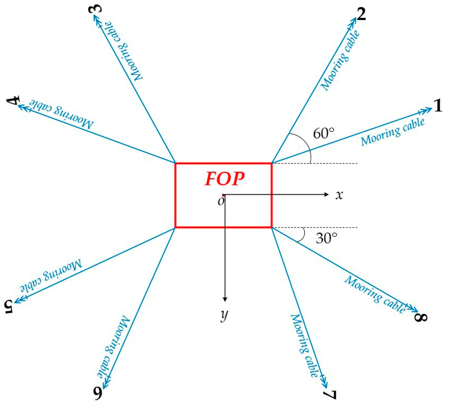
The mooring system of the “Kantan3” semi-submersible offshore platform consists of 8 anchor chains. The name order of the anchor chains is numbered counterclockwise. The anchor chain arrangement of the moored platform is shown in Figure 3. The angles of each anchor chain, the position of the fairlead hole, and the coordinates of the anchor point are shown in Table 1. The initial pretension of the mooring cable is 1.2 MN to ensure that the horizontal offset of the platform is within the appropriate range. The resultant force and moment limits provided by the eight-point mooring in the horizontal direction are shown in Table 2.
A first-order Markov process is used to describe the unknown external environmental disturbances suffered by the FOP [25], as follows:
w = R T ( ψ ) b b ˙ = T c 1 b + ς ϖ
where b R 3 is the external environment interference vector of the semi-submersible platform in the earth-fixed coordinate frame; T c R 3 × 3 is the designed diagonal matrix of time constants; ϖ R 3 × 3 is the zero-mean Gaussian white noise vector; ς R 3 × 3 is a diagonal matrix with scaled amplitudes of ϖ .
The MPMS control law proposed in this paper is used to simulate two different external disturbances corresponding to different sea conditions and is compared with the traditional PID control law.
τ P I D = K P S 1 ( t ) + K I 0 t S 1 ( t ) d t + K D S ˙ 1 ( t )
where K P = diag(1.2 × 10⁶, 1.5 × 10⁶, 3.2 × 10⁹), K I = diag(15, 15, 15), K D = diag(5 × 10⁷, 5 × 10⁷, 5 × 10¹⁰).
Case 1: Choose b(0) = [0, 0, 0]T, ς = diag(5 × 10³, 5 × 10³, 5 × 10⁴), T c = diag(103, 103, 103). Set desired position and heading for FOP as η d = [15 m, 15 m, 10°]T, and the initial states are η(0) = [0 m, 0 m, 0°]T, ν(0) = [0 m/s, 0 m/s, 0°/s]T, w(0) = [0, 0, 0]T, δ(0) = [0.1, 0.1, 0.1]T. The controller design parameters are ρ = [5 × 10⁻³, 5 × 10⁻³, 1 × 10⁻⁴]T, K 0 = diag(2, 2, 2), K 1 = diag(1.5, 1.5, 1.5), K 2 = diag(3 × 10⁵, 6 × 10⁵, 3 × 10⁸), K ξ = diag(20, 20, 20), T d = 0.8, Θ = 10−6 × diag(1, 1, 10−4), Π = 104 × diag(1, 1, 3 × 10³).
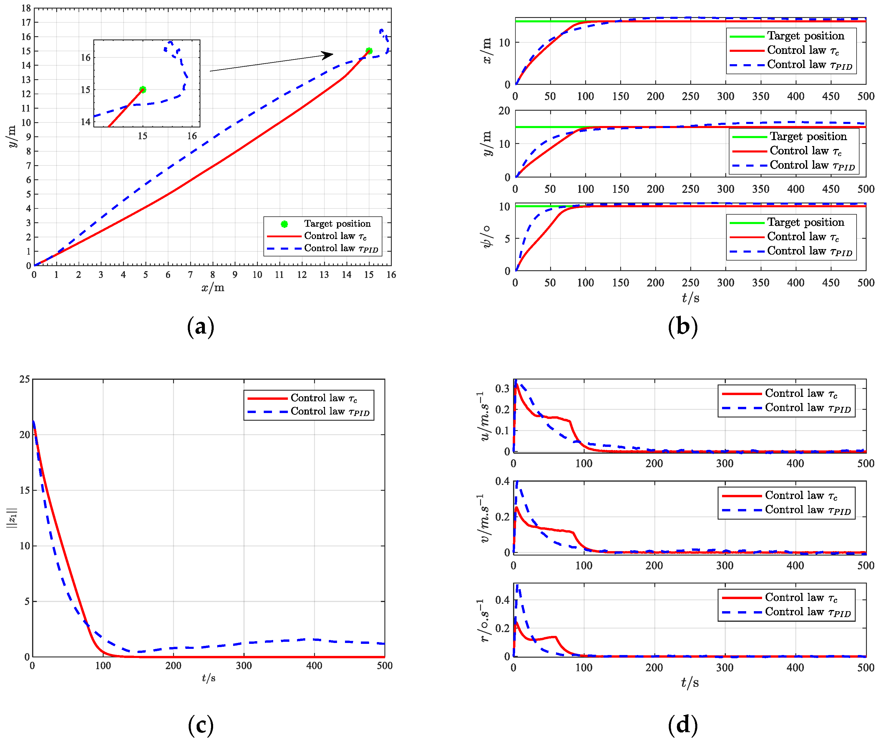
The simulation results of Case 1 are shown in Figure 4a–h. Figure 4a–c shows the positioning and tracking performance of the FOP. Both control laws can adjust the platform to the desired position. In comparison, the PID control law has a fast response speed, but the MPMS control law has a higher positioning accuracy, reaching within 3% of the working water depth. Figure 4d shows the curves of the surge velocity, sway velocity, and yaw angular velocity of the FOP. Under the MPMS control law, the speed of the FOP is smoother, avoiding excessive change rate of the mooring system force, which causes the anchor machine to jump. 
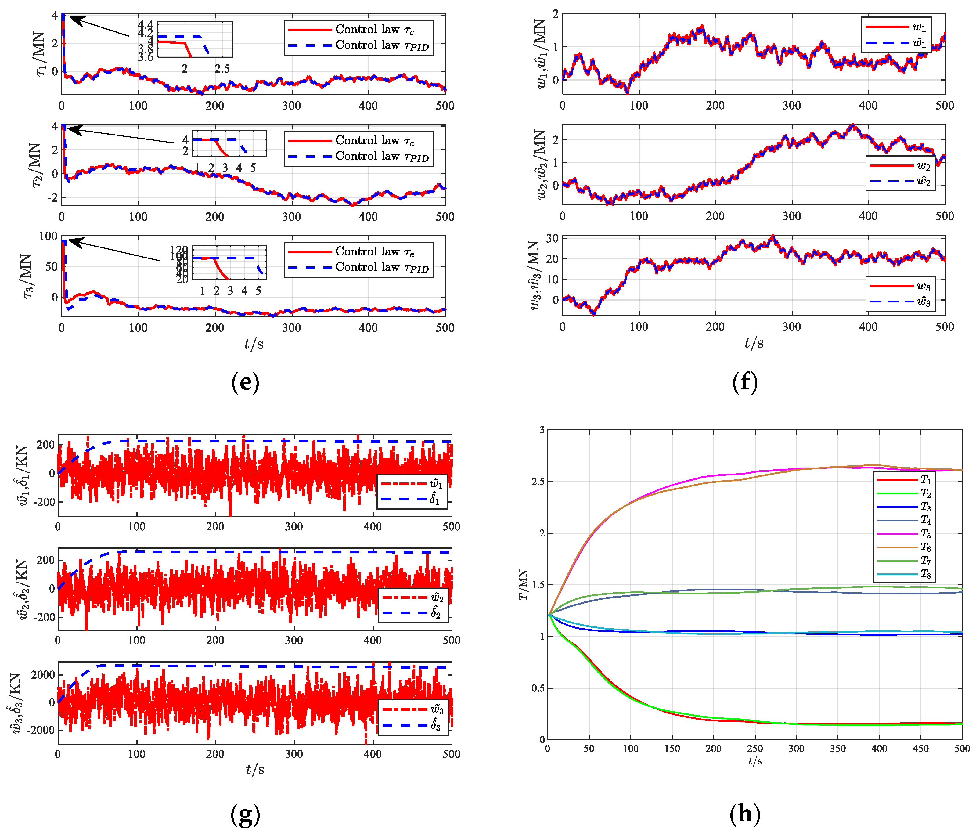
Figure 4e shows the boundedness of the control inputs τ 1 , τ 2 , and τ 3 . Under the control input constraints, the input constraint time of the MPMS control law is 2 s, and the input constraint time of the PID control is 4.5 s, which effectively avoids serious drift or even shutdown of the platform due to the breakage of the mooring cable. Figure 4f shows that the constructed disturbance observer can provide an estimate of the unknown time-varying disturbance. Figure 4g shows the error values of the interference observation on each component and the upper limit of the error of the adaptive estimation. Figure 4h shows that the FOP is positioned to the desired position under the initial pre-tension of the mooring cable. The tension curves of the eight mooring cables change smoothly, and the tension distribution between the mooring cables at the same position is uniform.
Case 2: Select b(0) = [0, 0, 0]T, T c = diag(103, 103, 103) the same as Case 1, and increase ς = diag(5 × 10⁵, 5 × 10⁵, 5 × 10⁶) to 100 times that of Case 1. The simulation initial conditions and controller parameter design are the same as those in Case 1. The robustness of the proposed MPMS control law is verified when the platform is simulated under extreme sea conditions.
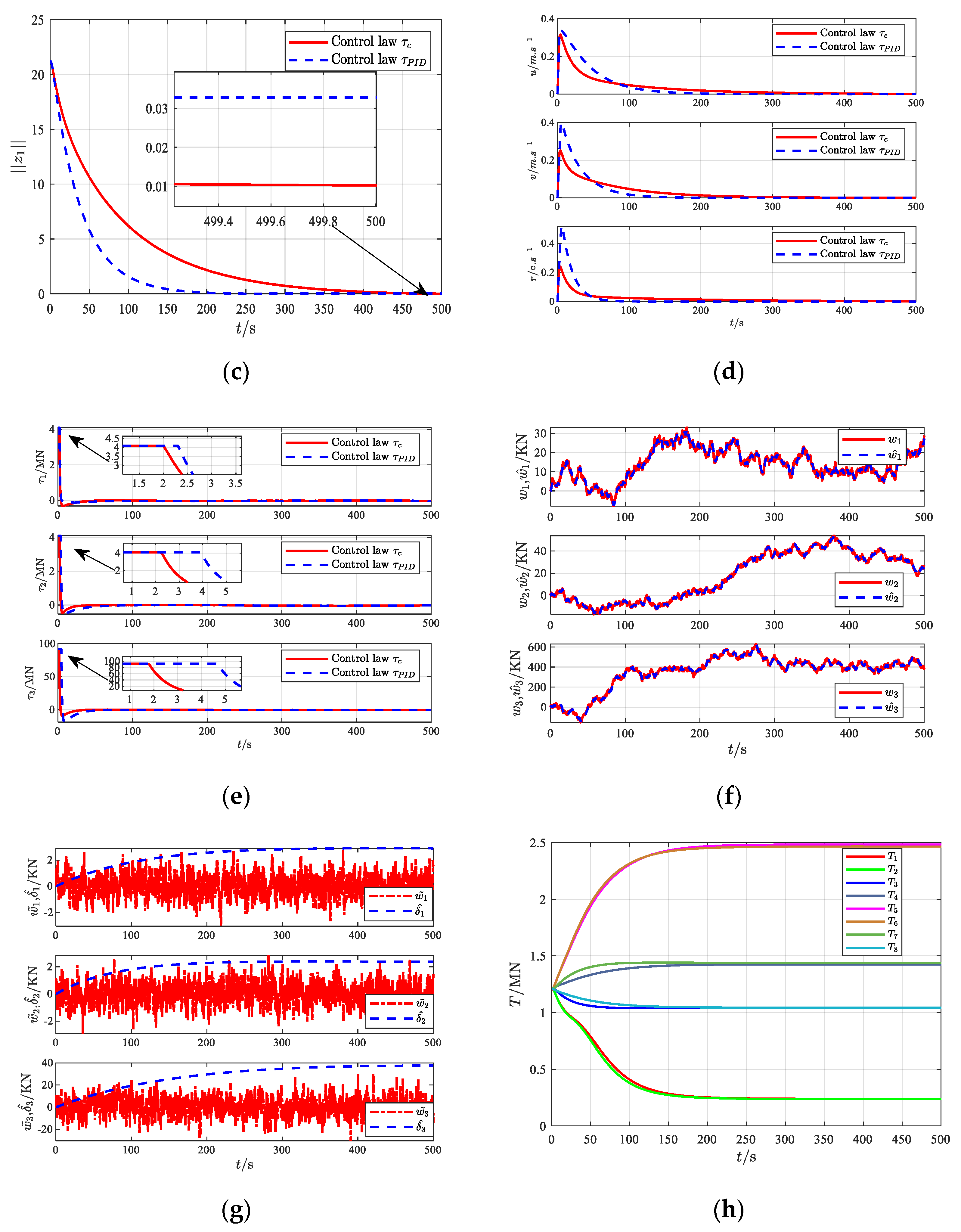
The simulation results of Case 2 are shown in Figure 5a–h. It can be seen from Figure 4a–c and Figure 5a–c that the proposed MPMS control law shows excellent positioning performance in both Cases 1 and Cases 2. When the external unknown environmental disturbance increases, under the MPMS control law, it takes 150 s for the FOP to locate the target position, while under the traditional PID control law, the FOP drifts and the positioning performance is poor, indicating that the proposed MPMS control law has excellent robustness to external disturbances. As shown in Figure 5d, under the MPMS control law, the surge speed, sway speed, and yaw rate of the FOP gradually decrease, and the speed changes more gently, effectively avoiding the breakage of the mooring line caused by the sudden change in the windlass speed. As shown in Figure 5e, when the external unknown environmental disturbance increases, under the control input constraint condition, the input restricted time of the MPMS control law is the same as Case 1, which is 2 s, and the input restricted time of the PID control law increases to 4.8 s. Figure 5f,g show that the constructed disturbance observer can provide the estimated value of the unknown time-varying disturbance in each component and the disturbance observation error value, as well as the upper limit of the adaptive estimation error. The results show that the adaptive law parameters of the σ-corrected leakage term are properly selected and there is no drift phenomenon. Figure 5h shows that when the external unknown environmental disturbance increases, in order to resist the external environmental disturbance, the tension of the 8 mooring cables changes slightly and then stabilizes when the FOP is positioned to the desired position. The results show that the proposed MPMS control law has achieved satisfactory control effects, which can not only ensure the positioning requirements of the FOP but also take into account the uniform distribution of the mooring cable tension field. Therefore, the proposed MPMS control law is more effective for FOP MPMS with dynamic uncertainties, external time-varying disturbances, and input constraints.

5. Conclusions

A RADS positioning control scheme with a disturbance observer is proposed for the FOP eight-point mooring positioning system with unknown time-varying disturbance and limited anchor chain tension input. The robust nonlinear control law of MPMS is established by using disturbance observer, ADS and DSC technology. The disturbance observer is constructed to estimate the unknown time-varying disturbance, and its feedforward control is used to compensate for the control quantity, effectively weakening the chattering. The adaptive law of the σ-corrected leakage term is used to estimate the bound of the disturbance observer error, and the hyperbolic tangent function is used to further eliminate the jitter. The introduction of DSC technology eliminates the computational complexity caused by the traditional back-stepping method in the virtual control derivation process. The Lyapunov function is applied to prove that the control law can ensure the consistent ultimate boundedness of the closed-loop signal and realize the multi-point mooring positioning of FOP. Finally, the simulation test is carried out on the “Kantan3” eight-point mooring platform. Through the simulation and comparison of the MPMS control law and the PID control law, the designed controller has smooth and reasonable control force and torque, high positioning accuracy, and meets the actual operation requirements of the MPMS, verifying the validity of the MPMS control scheme.

Author Contributions

Conceptualization, R.L. (Run Lu); methodology, R.L. (Run Lu) and G.Z.; Software, R.L. (Run Lu); Validation, R.L. (Run Lu); writing—original draft preparation, R.L. (Run Lu); writing—review and editing, R.L. (Ru Liu), C.G., W.C. and H.F.; funding acquisition, G.Z. All authors have read and agreed to the published version of the manuscript.

Funding

This research was funded by the National Natural Science Foundation of China, grant number 51779136; Key Technologies for Hybrid Optimization Control of CPP propulsion System Based on National Core components (NO H20230225).

Institutional Review Board Statement

Not applicable.

Informed Consent Statement

Not applicable.

Data Availability Statement

The data that support the findings of this study will be available from the corresponding author upon reasonable request.

Acknowledgments

The authors would like to thank the Shanghai Marine Equipment Research Institute for its advice and support.

Conflicts of Interest

Authors Ru Liu, Chaojian Gao, Wei Chen and Huanglong Fu were employed by the Shanghai Marine Equipment Research Institute Co., Ltd. The remaining authors declare that the research was conducted in the absence of any commercial or financial relationships that could be construed as a potential conflict of interest.

References

  1. Gottlieb, O.; Yim, S.C. Nonlinear oscillations, bifurcations and chaos in a multi-point mooring system with a geometric nonlinearity. Appl. Ocean. Res. 1992, 14, 241–257. [Google Scholar] [CrossRef]
  2. Veksler, A.; Johansen, T.A.; Borrelli, F.; Realfsen, B. Dynamic positioning with model predictive control. IEEE T Contr Syst. Technol. 2016, 24, 1340–1353. [Google Scholar] [CrossRef]
  3. Hu, X.; Du, J. Robust nonlinear control design for dynamic positioning of marine vessels with thruster system dynamics. Nonlinear Dynam 2018, 94, 365–376. [Google Scholar] [CrossRef]
  4. Villa-Caro, R.; Carral, J.C.; Fraguela, J.Á.; López, M.; Carral, L. A review of ship mooring systems. Brodogradnja 2018, 69, 123–149. [Google Scholar] [CrossRef]
  5. Zhou, S.L.; Nie, W.; Bai, Y. Investigation on mooring system design of a deepwater semi-submersible platform. J. Ship Mech. 2010, 14, 495–502. [Google Scholar]
  6. Felix-Gonzalez, I.; Mercier, R.S. Optimized design of statically equivalent mooring systems. Ocean. Eng. 2016, 111, 384–397. [Google Scholar] [CrossRef]
  7. Karimi, H.R.; Lu, Y. Guidance and control methodologies for marine vehicles: A survey. Control Eng. Pract. 2021, 111, 104785. [Google Scholar] [CrossRef]
  8. Kim, Y. A study on the control system design for ship mooring winch system. J. Mech. Sci. Technol. 2014, 28, 1065–1072. [Google Scholar] [CrossRef]
  9. Nguyen, D.H.; Nguyen, D.T.; Quek, S.T.; Sørensen, A.J. Control of marine riser end angles by position mooring. Control Eng. Pract. 2010, 18, 1013–1021. [Google Scholar] [CrossRef]
  10. Zhang, G.; Lu, R.; Chen, M. DRNN-MIMO-PID control strategy for multi-point mooring system. Int. J. Veh. Des. 2023, 91, 138–160. [Google Scholar] [CrossRef]
  11. Ji, S.W.; Balachandran, B.; Kim, Y.B. Robust control allocation design for marine vessel. Ocean. Eng. 2013, 63, 105–111. [Google Scholar] [CrossRef]
  12. Ji, S.W.; Choi, M.S.; Kim, Y.B. A study on position mooring system design for the vessel moored by mooring lines. IEEE-ASME T Mech. 2015, 20, 2824–2831. [Google Scholar] [CrossRef]
  13. Zhou, Y.; Zhang, X.; Chen, J.; Liu, R.; Sun, J.; Si, Y. Catenary Mooring Length Control for Motion Mitigation of Semi-Submersible Floating Wind Turbines. J. Mar. Sci. Eng. 2024, 12, 628. [Google Scholar] [CrossRef]
  14. Su, X.; Jin, H.; Shen, W.; Gu, Y. Delay-Range-Dependent H Control for Automatic Mooring Positioning System with Time-Varying Input Delay. Shock. Vib. 2014, 2014, 123107. [Google Scholar]
  15. Zhang, G.; Lu, R.; Chen, M. A Stable Self-Learning DRNN-PID Control of Multi-Point Mooring System. In Advances in Guidance, Navigation and Control, Proceedings of the ICGNC 2020, Tianjin, China, 23–25 October 2020; Springer: Singapore, 2022; pp. 4769–4779. [Google Scholar]
  16. Shin, H.; Seo, D.; Park, J. Fuzzy-based adaptive control method for automatic mooring systems. Ocean. Eng. 2024, 302, 117623. [Google Scholar] [CrossRef]
  17. Wang, Y.; Zhang, X.; Zhang, X. Nonsingular fast terminal sliding mode-based robust adaptive structural reliable position-mooring control with uncertainty estimation. Ocean. Eng. 2022, 253, 111329. [Google Scholar] [CrossRef]
  18. Zhang, X.; Wang, Y.; Chemori, A. Structural reliability based energy-efficient arctic position mooring control of moored offshore structures under ice loads. Ocean. Eng. 2023, 268, 113435. [Google Scholar] [CrossRef]
  19. Mao, Y.; Wang, T.; Duan, M. A DNN-based approach to predict dynamic mooring tensions for semi-submersible platform under a mooring line failure condition. Ocean. Eng. 2022, 266, 112767. [Google Scholar] [CrossRef]
  20. Cheng, S.; Yu, Y.; Zhang, P.; Zhang, B.; Cui, Y.; Huang, Z.; Yang, Z. Research on motion control of the semi-submersible platform under the mooring line failure. Ocean. Eng. 2023, 287, 115877. [Google Scholar] [CrossRef]
  21. He, N.; Gao, Q.; Gutierrez, H. Robust adaptive dynamic surface control for hypersonic vehicles. Nonlinear Dynam 2018, 93, 1109–1120. [Google Scholar] [CrossRef]
  22. Yang, C.; Wu, Z. Adaptive robust maneuvering control for nonlinear systems via dynamic surface technique. Nonlinear Dynam 2023, 111, 8369–8381. [Google Scholar] [CrossRef]
  23. Hamedani, M.; Selvaggio, M.; Rahimkhani, M. Robust dynamic surface control of da Vinci robot manipulator considering uncertainties: A fuzzy based approach. In Proceedings of the 2019 7th International Conference on Robotics and Mechatronics, Tehran, Iran, 20–21 November 2019; pp. 418–423. [Google Scholar]
  24. Fossen, T.I. Handbook of Marine Craft Hydrodynamics and Motion Control; John Willy & Sons Ltd.: Hoboken, NJ, USA, 2011; Chapter 7; pp. 133–186. [Google Scholar]
  25. Hu, X.; Du, J.; Sun, Y. Robust adaptive control for dynamic positioning of ships. IEEE J. Ocean. Eng. 2017, 42, 826–835. [Google Scholar] [CrossRef]
Figure 1. MPMS coordinate frames.
Jmse 13 00030 g001
Figure 2. Positioning principle diagram of MPMS.
Jmse 13 00030 g002
Figure 3. Eight-point mooring system diagram.
Jmse 13 00030 g003
Figure 4. Simulation results under τ c and τ P I D in Case 1. (a) Platform horizontal motion trajectory; (b) Platform position (x, y) and heading ψ; (c) Tracking performance z 1 ; (d) Platform velocity u, v, r; (e) Control input τ 1 , τ 2 , τ 3 ; (f) Disturbances w 1 , w 2 , w 3 and estimated values w ^ 1 , w ^ 2 , w ^ 3 ; (g) Disturbance observation errors w ˜ 1 , w ˜ 2 , w ˜ 3 and upper bound estimates δ ^ 1 , δ ^ 2 , δ ^ 3 ; (h) Tension of the eight mooring cables.
Jmse 13 00030 g004aJmse 13 00030 g004b
Figure 5. Simulation results under τ c and τ P I D in Case 2. (a) Platform horizontal motion trajectory; (b) Platform position (x, y) and heading ψ; (c) Tracking performance z 1 ; (d) Platform velocity u, v, r; (e) Control input τ 1 , τ 2 , τ 3 ; (f) Disturbances w 1 , w 2 , w 3 and estimated values w ^ 1 , w ^ 2 , w ^ 3 ; (g) Disturbance observation errors w ˜ 1 , w ˜ 2 , w ˜ 3 and upper bound estimates δ ^ 1 , δ ^ 2 , δ ^ 3 ; (h) Tension of the eight mooring cables.
Jmse 13 00030 g005aJmse 13 00030 g005b
Table 1. “Kantan3” fairlead and anchoring point coordinates.
Nox-Axis
Angle
Fairlead Coordinates/mAnchor Point Coordinates/m
XYZXYZ
130453514.51060.83612.47−250
260453514.5610.561057.52−250
3120−453514.5−610.561057.52−250
4150−453514.5−1060.83612.47−250
5210−45−3514.5−1060.83−612.47−250
6240−45−3514.5−610.56−1057.52−250
730045−3514.5610.56−1057.52−250
833045−3514.51060.83−612.47−250
Table 2. Limited input of “Kantan3”.
τ max τ min
τ 1 max = 4.175 ( M N ) τ 1 min = 4.175 ( M N )
τ 2 max = 4.175 ( M N ) τ 2 min = 4.175 ( M N )
τ 3 max = 92.25 ( M N ) τ 3 min = 92.25 ( M N )
Disclaimer/Publisher’s Note: The statements, opinions and data contained in all publications are solely those of the individual author(s) and contributor(s) and not of MDPI and/or the editor(s). MDPI and/or the editor(s) disclaim responsibility for any injury to people or property resulting from any ideas, methods, instructions or products referred to in the content.

