Abstract
In response to the anticipated scarcity of terrestrial land resources in the coming years, the acquisition of marine mineral resources is imperative. This paper mainly summarizes the development of underwater collection and transportation equipment of polymetallic nodules in deep-sea mining. Firstly, the collection equipment is reviewed. The deep-sea mining vehicle (DSMV), as the key equipment of the collection equipment, mainly includes the collecting device and the walking device. The micro and macro properties of sediments have a great influence on the collection efficiency of mining vehicles. For the collecting device, the optimization of the jet head structure and the solid–liquid two-phase flow transport of the hose are discussed. The structure of the walking device restricts mining efficiency. The optimization of the geometric structure is studied, and the geometric passability and lightweight design of the walking device are discussed. Secondly, the core of transportation equipment is the lifting device composed of a riser and lifting pump. In order to explore the key factors affecting mineral transport, the lifting device is summarized, and the design optimization of the lifting pump and the factors affecting the stability of the riser are discussed. Then, the relationship between each device is discussed, and the overall coupling of the device is summarized. Finally, the existing problems and future research focus are summarized.
1. Introduction
With the rapid development of industrialization, the demand for rare minerals in high-tech industries has increased sharply, and terrestrial mineral resources have been unable to meet the growing demand [1,2]. Countries began to focus on the vast majority of the earth’s oceans. The ocean’s depths hold abundant reserves of precious metal minerals, including polymetallic nodules, cobalt rich crust, and polymetallic sulfides. It has been estimated that the global quantity of metallic nodules present in our oceans amounts to approximately 500 billion tons. The deep ocean’s abundant reserves of valuable metals have captured the attention of numerous nations. The extraction of resources from the depths of the sea has emerged as a crucial strategic objective for leading global economies [3,4].
Polymetallic nodules, cobalt rich crust, and polymetallic sulphides are the typical marine mineral resources at present. Polymetallic nodules are potato-shaped and widely distributed in 4000–6000 m of deep-sea basin sediment surfaces [5]. Cobalt-rich crust is attached to seamount mountains, ridge tops, and survey surfaces, or exposed bedrock surfaces at 800–2500 m [6]. Polymetallic sulfides are distributed near hydrothermal vents. Figure 1 shows the distribution of the three major minerals.
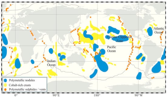
Figure 1.
Distribution of the three major minerals in the global ocean [7].
Polymetallic nodules have the greatest mining potential. Polymetallic nodules are rich in a variety of metals that are scarce on land and are rich in commercial value. They are considered the most critical alternative resources for land minerals and have become an increasingly strategic objective of major economies [8]. However, the operating environment inside the deep-sea is extremely harsh and complex, and still, only a few commercial organizations and countries are able to make use of deep-sea minerals. There are many operational problems in the deep-sea environment, such as the interaction of various mining devices [9], soft deep-sea geological environment, low temperature, and high pressure [10].
This paper summarizes the latest development of underwater polymetallic nodule collection and transportation equipment, and the problems encountered in the process of its optimization are discussed, reviews existing research on deep-sea mining systems, and presents problems and future directions for the equipment. The research focuses on collecting, walking, and lifting devices, and the interaction between each device is introduced in this paper. The research framework is shown in Figure 2.
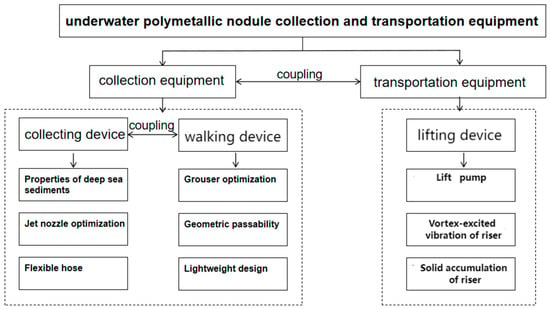
Figure 2.
Research frame diagram of underwater polymetallic nodule collection and transportation equipment.
2. Current Development of Deep-Sea Mining Systems
Four major mining systems have been proposed for the exploitation of deep-sea polymetallic nodules (DSPN) over the past few decades: submarine drag bucket mining system [2], continuous line bucket mining system [11], shuttle vessel mining system [12], and pipeline-lift mining system [13] (Figure 3). The pipeline-lift mining system is considered to be the most efficient system after offshore tests, cost control, and mining difficulty are proven [14]. The system includes three main parts: the surface support vessel, the hoisting system, and the DSMV. Among them, the DSMV traveling on tender deep-sea sediments relies on the walking device to maintain its passing performance and collects the polymetallic nodules on the seabed through the collecting system. The nodule minerals gathered by the DSMV are delivered to the relay station for crushing treatment through the connecting hose, and the riser and lifting pump in the riser lifting devices transport the collected polymetallic nodules to the mining vessel [15]. The mining vessel classifies and treats the transported polymetallic nodules and sends signals to the deep-sea mining vehicle. Cobalt-rich crusts are usually collected by screw rollers that are crushed and stripped from the bedrock [16]. Polymetallic sulfides are mined in a similar way to cobalt-rich crusts, and the ore is lifted to the surface through the lifting system after mining operations [17]. How to reduce the impact of each underwater device on the environment during mining is also a key issue in equipment research. As mining continues, the dispersion of fine sediment disturbed by mining may change over time, and plume monitoring and vulnerable species mapping must be rationed to adjust mining operations and minimize impacts outside the mine site [18,19].
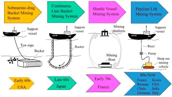
Figure 3.
Development of deep-sea mining systems [2].
DSMV is the core component of most deep-sea mining [20]. Deep-sea polymetallic nodule (DSPN) mining is the key goal of deep-sea mining in various countries, and the internationally recognized deep-sea mining system is generally composed of a surface working mother vessel with certain power and mineral resource storage capacity, and the mining system and mineral transportation system carried by them [21]. This mining system has been developed and designed in many countries [22].
In 1978, the Ocean Management Incorporated (OMI) developed a pipeline lift mining system composed of three parts: collecting, lifting, and a surface support vessel. The sea test was carried out from a water depth of 5000 m, and 800 t of manganese nodule was extracted, indicating that the system had technical feasibility in deep-sea operations. The German Institut für Konstruktion (IKS) and the University of Siegen in Germany jointly designed a DSMV, which was tested in 2001 for a short period of sand and silt mining at a depth of 410 m [1]. In 2002, the Japan Oil, Gas and Metals National Corp conducted a mining vehicle experiment at a water depth of 1600 m [23]. In 2013 and 2015, the Korea Advanced Institute of Ocean Science and Technology conducted sea trials for deep-sea mining vehicles and hydraulic lifting systems, respectively. CSU and Cebynetic developed second-generation DSMV [10]. However, no mature development pattern of marine mineral wealth exists globally, nor has commercial exploitation been realized in developed countries.
3. Deep-Sea Mining System Collecting Device
DSPNs are scattered on deep-sea sediments and are collected by the collecting device. The main composition of the DSMV is shown in Figure 4. Polymetallic nodules are scattered on deep-sea sediments (DSS) and are collected by deep-sea mining system collecting devices. Currently, there are three kinds of collection heads commonly used, including suction type, Coandă type, and double-row type (Figure 5). The parameters of jet nozzles in collecting devices affect the efficiency of jet collection. Meanwhile, the flexible pipe is directly connected to the collecting device. Because of the complex nature of the deep-sea environment, the position of the flexible hose and the collection device is often changed, so the flexible pipe is often in a horizontal and vertical state. Therefore, it is also very important to optimize the design of the flexible pipe and its internal solid–liquid two-phase flow conveying [7].
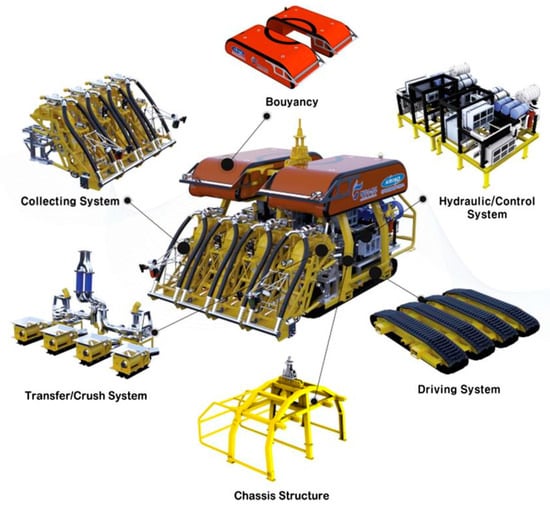
Figure 4.
Detailed drawing of a mining vehicle [24].

Figure 5.
Three kinds of collection heads. (a) Suction type; (b) double-row type; (c) Coandă type.
3.1. Properties of Deep-Sea Sediments
Many studies for deep-sea sediment characterization are presented, especially because of their unique high-pressure saline sedimentary environment. Deep-sea sediments are different in nature from terrestrial soils, characterized by ultra-high water content, ultra-small internal friction angle, ultra-large porosity, high liquid limit, high plasticity, high sensitivity, high compressibility, and low density [25,26,27,28,29,30,31,32]. Their physical and chemical properties and microstructure are significantly different from those of land soil and inshore soil.
In an effort to research the impact of mechanical disturbance on the microscopic peculiarity of DSS, Nian et al. [23] conducted electron microscope scanning on the deep-sea sediments undisturbed and under different disturbance forces, the microstructure consists of a sheet-like link structure and honeycomb-like flocculation structure co-existing and filling each other [33]. Their microstructure is shown in Figure 6. The data from 41 measuring points in the eastern Pacific mining area showed that both the shear strength and penetration resistance of the bottom material increased with increasing test depth, reached a maximum value, and then decreased slightly [34]. With the deepening of depth, the state of the sediment gradually changes, from fluid to fluid-plastic to plastic [28,35]. In the flow-like state, the shear strength is minimal and has no engineering significance. In the flow-plastic state, the shear characteristics change significantly, the shear strength increases sharply, and the grouser tip damage is accelerated. At the same time, the track plate collapses rapidly, and the driving resistance increases sharply. In the plastic state, the shear performance is uniform, the shear strength is slowly reduced, and it can be used as the traction layer of the deep-sea mining vehicles walking track [24].
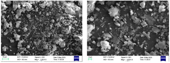
Figure 6.
Scanning electron microscope images of remodeled samples.
3.2. Jet Nozzle Parameter Design
As the core component of the jet collecting device, nozzles mainly include circular nozzles and Venturi nozzles [36] (Figure 7). The main function of the nozzle is converting the pressure energy in the jet into kinetic energy, causing the jet to shoot out at a high speed. The structure of the nozzle has a strong impact on the hydrodynamic properties of the water jet. In recent years, the effect of different nozzle parameters on water jetting has been extensively studied by many scholars [37]. The working mechanism is shown in Figure 8.

Figure 7.
Nozzle details. (a) Circular nozzle; (b) Venturi nozzle [38].
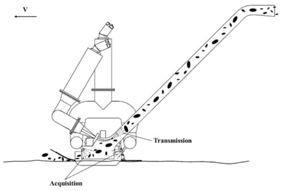
Figure 8.
Schematic of the operating principle of the front collector [39].
The scour problem resulting from water jet was first addressed by Rouse et al. [40]. Subsequently, Tastan et al. [41] researched the influence of sedimentary layers on jet scour. Many scholars have investigated how nozzle type, nozzle size, impact angle, and impact velocity affect fluid jets [42,43]. Baylar et al. [42] compared Venturi nozzles with circular nozzles and found that Venturi nozzles were much more efficient than circular nozzles. Kartal et al. [44] studied the influence of circulating water jet on the scouring depth. By changing the thermodynamic and structural parameters of the nozzle plate and no plate, it was shown that the nozzle plate plays a leading role in the nozzle head. Wang et al. [45] studied the change law of nozzle injection coefficient with the working pressure of the injector, and the influence of the nozzle with different thermal and structural parameters on the performance of the injector was obtained. Yao et al. [46] studied the effects of high-pressure common rail nozzle structure on hydrodynamic characteristics by using a three-dimensional phase Doppler particle analyzer and the particle size distribution trend of the jets was obtained. Veysi et al. [38] conducted an experimental study on the local scour generated by water jets from different types of nozzles and made a detailed analysis of static scour depth, the change of scour with time, scour features, the influence of nozzle types on scour, and the air entraining rate of various nozzles. The experimental design is illustrated in Figure 9. Based on numerical analysis, Shi et al. [47] obtained the numerical simulation water phase diagram of pulsed water jets with nozzles of various structures, and the variation rules of distance and width of water jet were obtained.
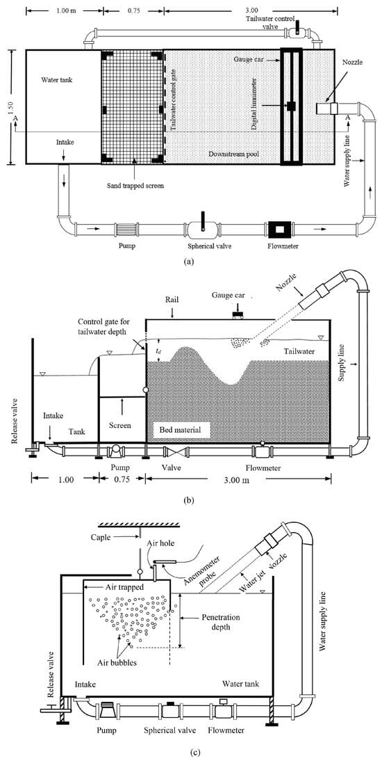
Figure 9.
Experimental setup. (a) Plan view; (b) longitudinal section; (c) air entrainment setup [38].
There are many papers on the structural parameters and stability of water jet devices, but there are still some shortcomings. The stability of water jets is critical to cutting accuracy and efficiency, but maintaining jet stability remains a challenge in high-speed, high-pressure, or long-distance jets. At the same time, the parameters of the water jet (such as pressure, velocity, nozzle design) have a significant impact on the performance, but how to optimize these parameters to achieve the best effect still needs further research.
3.3. Flexible Hose and Solid–Liquid Two-Phase Flow Transportation Optimization
There must be a section of flexible hose between the ore-collecting device and the lifting device, and different shapes may appear depending on the location of the ore collector and the main pipe; even close to the horizontal shape may appear, which is not conducive to the transportation of coarse granular ore. At the same time, due to the seabed crushing conditions and the environmental requirements of wastewater discharge, the particle size of the deep-sea ores transported is relatively coarse; coarse particles and the liquid phase cannot form a homogeneous slurry, which not only has complex resistance characteristics but also easily blocks the pipeline, which may cause serious engineering accidents. Consequently, it is particularly important to study the related problems of solid–liquid two-phase flow conveying in a horizontal hose.
Asakura et al. [48] researched the impact of fluid phase, collision, and composition term modeling in particle motion equations on particle concentration distribution and fluid velocity. During solid–liquid two-phase flow, the motion state in the solid phase also changes constantly with the change of the average velocity. Ye et al. [49] combined experimental and theoretical studies and established a new formula to reflect the resistance change in complex pipelines with average velocity. The paper reflected the relationship with other parameters. Mengmeng et al. [50,51] adopted computational fluid dynamics and the particle discrete element method to conduct a numerical study of the hydraulic transportation of coarse solid particles. As shown in Figure 10, the simulated horizontal pipeline studied the impact of solid concentration, particle diameter, and particle velocity on hydraulic transportation.

Figure 10.
Schematic diagram of simulated horizontal piping. (a) Geometry configuration; (b) computational grids on a cross-section [51].
Cao et al. [52] studied the hydraulic transport law of a horizontal hose through experiments and the calculation formula of additional pipeline loss was obtained, which provided a rationale for the parameter design of a coarse particle pipeline hydraulic transport system. Different from other flexible hoses, when flexible hoses are in the horizontal states, the solid–liquid two-phase flow has its unique flow characteristics, the coarse particles are easy to deposit, and the conveying parameters are difficult to determine. Many scholars have studied the hydraulic transportation characteristics of horizontal flexible hoses. Avi et al. [53] researched the flow properties of coarse particles in horizontal hydraulic transportation, they conducted a three-dimensional CFD-DEM simulation, and they obtained information about the hydraulic transportation of coarse particles in well-developed horizontal flow in pipelines, and the data were verified experimentally. A schematic of the simulation for different particle concentrations is shown in Figure 11.
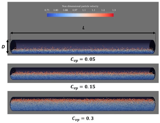
Figure 11.
Side view of CFD-DEM simulated periodic pipe [53].
In the meantime, the dragging of the flexible hose while the DSMV is driving compacts the sediment at the ruts or flips the sediment on either side before it is redeposited [54], which can influence the physical and mechanical properties of the DSS, as shown in Figure 12.
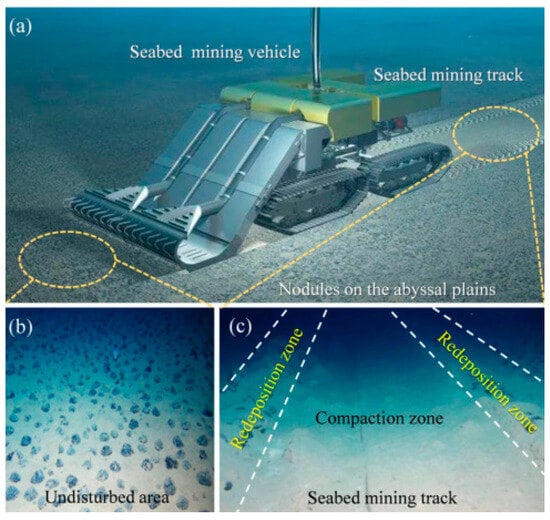
Figure 12.
The pre- and post-collection diagram of the DSMV. (a) Schematic diagram of sediment compaction driven by DSMV. (b) The pre-collection diagram. (c) The post-collection diagram [7,54].
4. Deep-Sea Mining System Walking Device
When the walking device is running on the DSS, the grouser directly interacts with the sediment. The study of the sediment properties and the influence of the grouser structure parameters on the traction force is the key factor in determining the travel of the mining vehicle. The diversity of natural ecological environments creates biodiversity, and nature provides researchers with a source of inspiration to solve major problems under complex conditions. In recent years, more and more studies have been conducted on biomimetic structures [55,56]. At the same time, due to the complex seabed topography and geological environment, the ability of a walking device to deal with the complex environment is essential. The body’s lightweight design can also reduce the pressure of the sediment on the body and improve its traction performance and collection efficiency.
4.1. Optimization of Mining Grouser Parameters
The grouser is the most critical structure in the DSMV walking device, and the driving force of the walking device is mainly generated by the sediment thrust on the grouser. The key to the research of the walking device is to establish the correct tractive force model. Optimization of the grouser structural parameters can also effectively improve its traction performance.
4.1.1. Track and Sediment Model Construction
The walking device of the mining vehicle acts on the sediment surface, and the track action will cause the deformation of the sediment and produce compressive and shear forces. When the DSMV is traveling over deep-sea sediments, it must have enough traction to ensure that it does not sink, slip, or overturn. Currently, the subsidence and tractive force calculation is mainly based on the Bekker theory [57]. Due to the increased pore ratio, elevated water content, and pronounced rheological properties of DSS in comparison to terrestrial soil, the Bekker theory cannot be employed for determining the tractive force of deep-sea mining vehicles without considering time effects.
The initial investigation by Schulte et al. [58] focused on examining how deep-sea sediment pressure influenced subsidence, allowing for the determination of both magnitude and timing of subsidence in static scenarios. Subsequent studies by Li et al. [59] as well as Wang et al. [60] involved conducting experiments specifically targeting shear deformation in relevant deep-sea sediments, revealing distinct stages within this process. As depicted in Figure 13, the deep-sea sediments exhibit a typical pattern of elastic-plastic deformation, which can be categorized into four distinct stages. Initially, during the linear elastic stage, there is a proportional increase in shear stress and displacement, with the dominance of elastic deformation. Subsequently, as it progresses to the strain-strengthening stage, there is a non-linear rise in both shear stress and displacement until reaching their peak. When it reaches the maximum point, the sediment enters a stage of strain softening. As displacement increases, there is a non-linear decrease in shear stress until complete destruction of the sediment occurs and stress reaches its residual level. Subsequently, shear stress stabilizes as displacement continues to increase. Finally, the shear stress remains consistent with the increase in displacement.
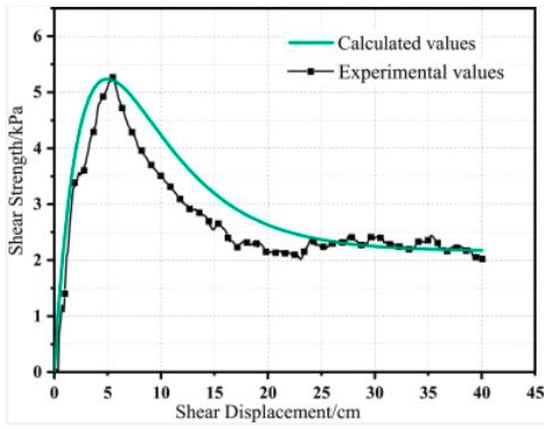
Figure 13.
Shear stress–shear displacement relationship curve [61].
Bekker’s elastoplastic constitutive model [57] is currently for the calculation of the subsidence and tractive force of DSMV, in which time-dependent effects (i.e., rheological properties) are not taken into account. As the crawler mining vehicle moves, the sediment undergoes simultaneous compression and shearing, which affects the subsidence of crawler mining vehicles. The compressive force as well as the shear force play a role in this phenomenon. Xu et al. [62] deduced a rheological model that combined compression and shear, utilizing the internal time theory. Its parameters were obtained through compression–shear-coupled experiments, and the measurement of its creep curve was conducted using a custom-built creep meter that combined compression and shear, which was verified by making simulated soil. The experimental model can predict the coupled compressor-shear rheological properties of deep-sea sediments. Under this compression-shear-coupled rheological model, the maximum subsidence tractive force is minimal, which can reflected the worst working conditions well. The model can provide the theoretical basis for the design and optimization of mining vehicle walking devices. Xu et al. [63] proved the compression–shear-coupled constitutive model of mining vehicle travel time and carried out experimental analysis. Zhang et al. [64] researched the vertical stress fluctuations and temporal distribution patterns of seabed sediments caused by the movement of DSMV on the ocean floor.
Deep-sea sediment tractive forces differ from those of sandy soils. Theoretical models derived from sandy soils are often used to evaluate soil tractive forces of cohesive soils. The tractive force of soil is determined by the shear force applied to the clod, which has the same shape as the track of the walking device. However, the shear properties of cohesive soil are very distinct from those of sandy soil, and the expected soil tractive force will also manifest in different forms [65,66]. In this context, Sung-Ha et al. [67] studied the soil tractive force mechanism, and a series of experiments with simulated soil on the model orbit system were conducted (Figure 14). They studied the soil tractive force mechanism of cohesive soil, established a tractive force prediction model of cohesive soil, and verified its applicability through comparative analysis, as depicted in Figure 15. For the purpose of dealing with the more complex track layout, Lubao et al. [68] adopted triple Fourier transform technology to obtain the dynamic three-dimensional distribution expression of the dynamic load distribution of a dual track. The enclosed formula can be employed in conjunction with theoretical approaches, whether elastic or plastic, to anticipate the operational outcomes of mining vehicles across diverse circumstances involving deep-sea sediments. The common schematic diagram of the double-track mining vehicle is depicted in Figure 16. Zhiyong et al. [69] established a mathematical model of pressure subsidence and tractive slippage of a four-track mining vehicle and verified its accuracy by numerical simulation. The DSMV model is shown in Figure 17.

Figure 14.
(a) Trimmed model ground; (b) reconstituted EPK kaolinite specimen; (c) schematic diagram of the model track experiments [67].
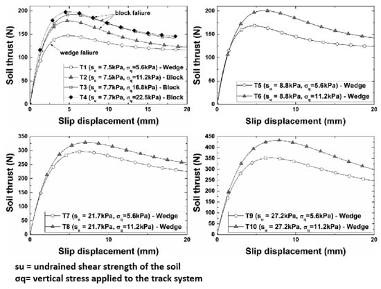
Figure 15.
Soil thrust–slip displacement relationships [67].
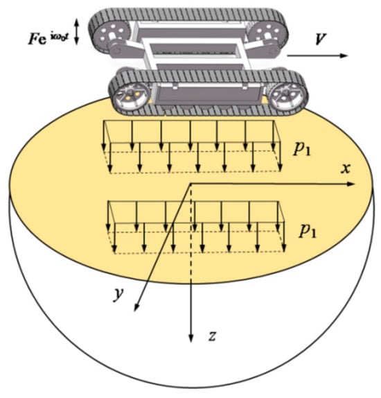
Figure 16.
Schematic of a DSMV with two caterpillar tracks [68].

Figure 17.
(a) The correlation between pressure and sinking of a mining vehicle with four tracks. (b) Illustration depicting the longitudinal section. (c) Schematic representation of the shear plane where the front and rear tracks cut through the seabed [69].
4.1.2. Optimization of Grouser Structure
The traction force obtained by the DSMV on the DSS depends on the track’s contact area and the grouser’s geometric characteristics [67]. The key is to optimize the parameters of the grouser, which can effectively improve its tractive performance.
For the track of mining vehicles, there are several types of track plates, such as the passive excavator proposed by Yong et al. [70], the active excavator, and the blade excavator proposed by Hong et al. [66]. Hong et al. [66] researched the grouser types of 18 models and evaluated the subsidence and traction of each grouser. Wang et al. [71] conducted preliminary experimental research on the tractive force induced by different shapes and sizes of grouser, but a theoretical structural model to obtain the maximum tractive force was lacking. Li et al. [72] examined how tractive performance is influenced by varying the height of the grouser, where the calculation formula of grouser height and tractive force through theoretical analysis were obtained, and experimental simulation was carried out. The results showed that with the rise in grouser height and slip rate, there was a significant surge in the overall propulsive force until it reached its maximum. Li et al. [73] surveyed the traction performance of tracks with different shapes, including π-shaped, T-shaped, and V-shaped tracks. By altering the structural parameters of these tracks, they established a correlation between the structural characteristics and their mechanical properties. The track structure and numerical simulation are shown in Figure 18.
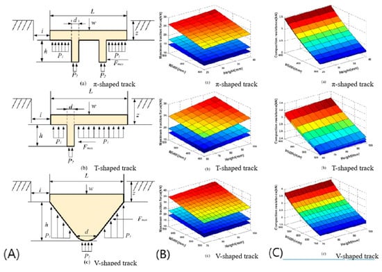
Figure 18.
Schematic of track structure and numerical simulation. (A) Force analysis of the different tracks on sediment; (B) variation rule of the maximum traction force; (C) variation rule of compaction resistance (a) π-shaped track. (b) T-shaped track. (c) V-shaped track [73].
Janarthanan et al. [74] used the coupling Euler–Lagrange (CEL) method in ABAQUS 2020 software to numerically simulate tracks with different structural parameters, and they verified the impact of grouser characteristics on the ability to generate traction and displace soil. Sun et al. [75] evaluated the impact of different parameters, i.e., different velocities, number of grousers, and composition of sediments by the coupling Euler–Lagrange method, where stress variation and disturbance data were obtained. Xu et al. [76] conducted compression–shear creep experiments on deep-sea sediments and obtained their rheological models. According to the experimental model, the formulae for calculating the tractive force of the thick-triangle track shoe and the sharp-triangle track shoe were deduced, and the optimal structure of the track plate was determined. The results of this experiment show the different applications of the two types of track plates. Finally, the validity of the model was verified.
4.1.3. Optimization Design of Bionic Grousers
Inspired by the theory of natural bionics, many studies have optimized the structure of crawler walking devices from the perspective of bionics based on the low shear strength and easy slipping of DSS. Based on the adaptability of buffalo hooves to walk in soft soil, Cai et al. [55] designed and optimized the shoe grouser according to the appearance of buffalo hooves. The relevant model of bionic grouser parameters and traction force was established by experiments, and the optimization algorithm yielded the optimal parameters for the finest bionic grouser. After analyzing the traction characteristics at various speeds, a correlation between speed and maximum traction force was established. Consequently, the optimal driving speed for the bionic grouser was determined.
Meanwhile, considering the strong adhesion properties of walking devices, researchers drew inspiration from burrowing animals [77], and bionic-based anti-adhesion machines were developed [78], which yielded successful outcomes. Wen-bo et al. [56], studied the adhesion of shoe grouser to deep-sea sediments. A bionic walking device was proposed based on the characteristics of burrowing animals, as shown in Figure 19. According to the DSS adhesion characteristics and discrete element method, a deep-sea sediment cutting model was established. A simulation experiment was performed on the designed grouser structure [56]. The experiment results demonstrated the efficient reduction in deep-sea sediment adhesion was achieved by the bionic grouser and such adhesion was minimized. The simulated soil was cut by a designed deep-sea mining vehicle, and its reliability was verified.
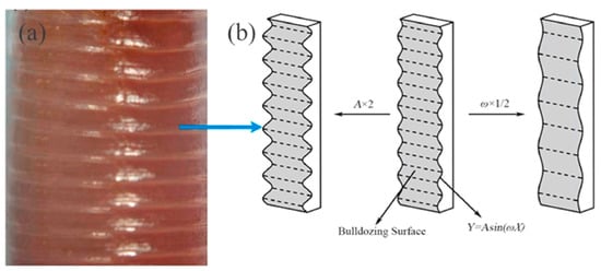
Figure 19.
Burrowing animals with bionic grouser. (a) Body morphology of earthworms; (b) bionic grouser (Surface waveform function: Y = Asin(ωX)) [55,79].
4.2. Geometric Passability of The Walking Device
The design requirement of a deep-sea mining vehicle walking device is to be able to run stably on deep-sea sediments and address intricate road circumstances due to the complex seabed environment, which requires the structural design of the walking device to possess the capacity to handle intricate road situations including climbing, steering, obstacle clearing, and anti-rollover capabilities.
Investigating the capability of mining vehicles to navigate challenging road conditions, Sung-Ha et al. [80] conducted a study on the lateral force exerted by tracked vehicles using the ram shear theory. Yong et al. [73] researched the correlation between structural parameters and traction capabilities of unmanned underwater tracked bulldozers. This study offers valuable insights into enhancing anti-skid measures and stability control for locomotive apparatus. Feng et al. [63] were the pioneers in deriving a novel equation to compute the steering grip of crawler mining vehicles by taking into account both the resistance encountered during propulsion and the sinking phenomenon. Furthermore, they investigated how turning speed, distance between tracks, and contact length between tracks and deep-sea sediments impact this steering grip. Zhang et al. [81] developed an intricate model based on multi-body dynamics to simulate different operational scenarios such as straight-line motion, steering maneuvers, uphill climbs, as well as traversing ditches for evaluating the overall performance of their crawler mining vehicle (CMV). Laboratory tests were performed by researchers to examine how deep-sea mining vehicles steer, climb, and cross obstacles. Numerical simulation experiments using RecurDyn V9R1 software were conducted to analyze the dynamic properties of these vehicles in various operational scenarios [82]. In another study by Yu et al. [83], a numerical analysis was carried out to investigate the intricate flow patterns during straight movement, steering maneuvers, and climbing actions. This research offers insights that can guide improvements in the design of mining vehicle structures. Additionally, Ouyang et al. [84] explored how deep-sea mining vehicles behave on inclined slopes sideways while establishing a mathematical model that relates tractive force to drag.
4.3. Lightweight Design of Vehicle Body Structure
Deep-sea mining vehicles, due to their significant weight, can easily become submerged in soft sediments. These sediments have a higher pore ratio, increased water content, lower shear strength, and more pronounced rheology. As a result, the mobility and efficiency of deep-sea mining vehicles may be compromised [85]. In general, to address this issue, one potential solution is to increase the amount of buoyant materials used in deep-sea mining vehicles, which would enhance their overall buoyancy. Nevertheless, the deep-sea mining vehicle will experience an increase in mass as a result of its volume expansion and create greater water resistance. The lightweight design of the body is an effective solution to reduce the sinking of the DSMV on the DSS, which is more simple and reduces the development cost and cycle. At the same time, the lightweight design of the body can further reduce the amount of buoyancy materials, further reduce the resistance of the DSMV, and effectively improve the traction performance of the walking device.
The premise of lightweight design is not to reduce the performance of the original mining vehicle. At present, lightweight design is widely used in underwater equipment to reduce cost and improve performance. Wu et al. [34] optimized the structure of the pressure vessel of the underwater glider with carbon fiber, and they verified the applicability of the optimization of the DSMV using carbon fiber material. Kang et al. [86] used a titanium and aluminum alloy to optimize the equipment of underwater gliders and found the best optimization scheme through experimental research, which reduced the body mass by 31% and adjusted the buoyancy by 26.4%.
Optimization of structural models is also often used in the lightweight design of structures. Li et al. [87] established an ellipsoidal function neural network model and optimized the arrangement and composition determined by the neural network approximation model. Zhang et al. [43] established an approximate response surface method model and used this model to improve the underwater vehicle. The improved hull had lower energy consumption and longer endurance. Li et al. [88] adopted the dual-agent model global optimization method to optimize the design of the underwater vehicle, which not only significantly improved its structural performance but also reduced its mass by 10.82%.
In the past, most of the lightweight designs were concentrated in underwater vehicles, and the research on the lightweight design of DSMV was relatively rare. Unlike underwater vehicles, DSMVs must be attached to the seabed to work. Pin-Jian Wang et al. [39] studied the lightweight design of the DSMV, mainly focusing on the lightweight design of the front collector (FC). The structure of the collector was optimized with different alloys. The stress contour map and displacement contour map of FC under the ultimate load at a depth of 6000 m in the deep-sea are depicted in Figure 20. Aluminum alloy and titanium alloy collectors of different materials were compared to ensure that the performance of their mining vehicles is not affected. The experimental results showed that the weight loss of aluminum alloy was the most significant, the weight loss rate was 19.22%, and the structural properties were also improved.
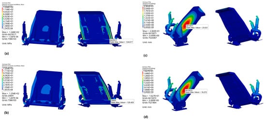
Figure 20.
Stress contour plots (a) aluminum alloy; (b) titaniun alloy, and displacement contour plots (c) aluminum alloy; (d) titaniun alloy [39].
In the forthcoming research, it is imperative to continue the lightweight design of the track walking device and the body. In addition, the optimized mining vehicle structure needs to test its structural performance in a real marine environment, thus verifying the effectiveness of the lightweight optimization design.
5. Deep-Sea Mining System Lifting Device
The lifting device of the deep-sea mining system transfers the solid–liquid two-phase flow of polymetallic nodules collected by the DSMV to the mining vessel. The core of the lifting device is the lifting pump and riser, and the lifting pump is the key driving force of the lifting device [89]. The marine riser is exposed to the complex marine environment, and the vortex-induced vibration (VIV) and solid accumulation caused by various factors inside and outside the pipe are also the key to the research of the riser.
5.1. Design Optimization of Lift Pump Structure
Most of the lifting pumps used in deep-sea mining lifting devices are multi-stage lifting pumps, whose structure is shown in Figure 21. The pipeline carries a mixture of solid and liquid, creating a two-phase flow. Due to the presence of solid minerals, wear, and blockage pose a serious threat to the dependability of the multistage lifting pump and the whole system in the riser lifting device. The examination of the internal workings behind the process of deterioration caused by friction and blockage in complex channels is a critical problem in the study of lifting pumps. Meanwhile, the current deep-sea mining system lifting pump adopts a high-speed ratio of a multi-stage lifting structure. Due to the continuous pressurization of the multi-stage lifting pump, the impeller axial thrust is too large, even up to dozens of tons, which seriously threatens the stable operation of the pump. Improper design of the balancing device can also lead to problems such as bearing overload and pump shaft fracture [90,91].

Figure 21.
Diagram illustrating the structure of multi-stage pumps used for lifting slurry 1: Inlet flange; 2: motor, 3: annular channel; 4: nut and bolt; 5: impeller; 6: diffuser with bowl; 7: outlet flange [92].
The flow field diagram of the lifting pump is shown in Figure 22. In order to find out the blockage law of solid–liquid two-phase flow, Wu et al. [93] researched the settling velocity equation of solid particles on the basis of theoretical analysis and experimental statistics. Some scholars pay attention to improving the anti-clogging performance and reasonably increasing the flow channel of the lifting pump; the increase flow method designs a larger lifting pump by enlarging the flow rate and specific velocity [94]. However, the lifting pump designed by this method is prone to backflow and flow separation, leading to unstable lifting pump operation and increased hydraulic loss [4]. So as to prevent the occurrence of wear and blockage in the lifting pump, it is essential to ensure that the design and optimization of its various components are carried out meticulously, thereby effectively addressing the aforementioned issues. The enhancement of the diffuser design in the lifting pump contributes to the enhancement of pump performance and particle passage capability, while the efficiency and head of the mud pump decline as the trailing edge angle of the diffuser blade increases [95]. The impeller’s outlet dimensions and the number of blades significantly impact the lifting pump. In addition, a limited quantity of blades has the potential to eradicate the protrusion in the water head curve, thereby diminishing hydraulic friction losses and obstructions, the number of blades to lift the pump impeller is generally selected [9]. The outlet angle of the impeller blade has a great influence on the performance of the pump, and it is advantageous to have a higher impeller outlet angle as it helps minimize both friction loss within the impeller and the overall radial size. The Korea Institute of Geological Marine Resources (KIGAM) established an experimental system to study lifting pumps [10].
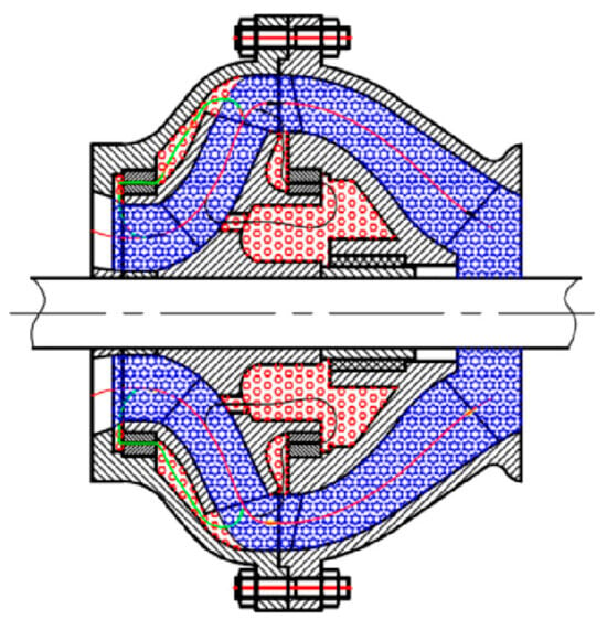
Figure 22.
Schematic diagram of the whole flow field. The blue hexagon region is the main flow field. The red hexagon region is the secondary flow field [96].
In view of the lateral thrust suffered by the lifting pump, although researchers have proposed a large number of theoretical formulas to evaluate the axial thrust of the pump, there is still a discrepancy observed between the computed outcomes and the recorded axial force during practical operational testing [97]. Therefore, more and more researchers study the actual axial thrust of the pump through tests. On the basis of research conducted by Badr and Ahmed et al. [98], the addition of a balance hole and a double sealing ring (as depicted in Figure 23) is an effective method for mitigating the axial thrust experienced by centrifugal pumps. Cao et al. [99] developed a centrifugal pump with eight recirculation holes to effectively minimize the overall axial thrust and conducted experiments to evaluate its effectiveness in reducing thrust forces. Wang et al. [20] conducted research on the dynamic flow behavior of pumps, specifically focusing on the assessment of hydraulic axial thrust. Elicio and Annese et al. [100] carried out experimental work on axial thrust, verified and calibrated the theoretical formulas, and obtained the deviation range of hydraulic axial thrust. Many scholars have carried out numerical simulations of axial thrust using numerical simulation methods. Considering the cost and cycle of experiments, some researchers employ numerical simulation techniques for forecasting axial thrust and flow properties [101,102]. Babayigit et al. [103] utilized CFD to assess the impact of the balance hole on the hydraulic efficiency of multistage pumps. In their study, Zhu et al. [104] performed numerical simulations and conducted experiments to investigate the axial force generated by the asymmetric blade structure of the lifting pump, based on the consideration of balancing plate and balancing hole. Kang et al. [96] conducted research on the axial force and counterbalancing strategies of deep-sea multistage lifting pumps while minimizing any adverse impact on hydraulic efficiency.
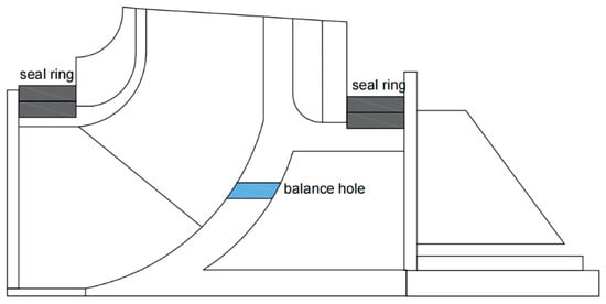
Figure 23.
Balance hole and a double sealing ring location diagram.
The existing research has made some progress in improving the axial thrust of the pump, including design optimization, fluid dynamics analysis, and performance testing of the pump. These studies help to improve pump efficiency, reduce energy consumption, and extend pump life. However, while existing pump designs have made progress in improving axial thrust, there may still be design limitations. At the same time, the research of lifting pump axial thrust often requires the knowledge of mechanical engineering, fluid mechanics, materials science, and other disciplines, and the existing research may not be fully cross-integrated.
5.2. Riser Structure Design
The marine riser holds significant importance among the various devices in the lifting system, which has a great slenderness ratio and will be affected by VIV and solid accumulation when transporting solid sediment. Extensive studies have been conducted by numerous academics regarding the accumulation of solids and VIV in marine risers. Compared with solid accumulation, vorticity vibration caused by the combination of internal and external excitation is the most critical problem in riser design. The external excitation includes the hydrodynamic force and wave motion of the floating platform, while the impact of internal flow is associated with internal excitation, as shown in Figure 24.
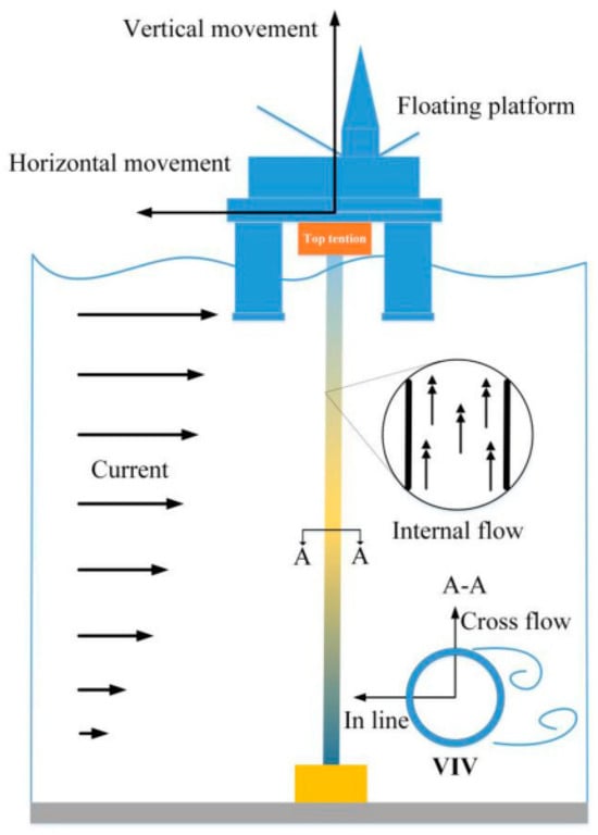
Figure 24.
The VIV of the riser systems under internal and external influences [94].
The irregular feed of the riser can cause solids to overtake each other or even form solid plugs to block the riser lift pipe. Evans and Shook [105] studied the axial dispersion of vertical transport using sand and fine gravel to explore the problems related to solid plugging. Talmon and Rhee [95] studied the transport process using advection diffusion equations in lifting devices. J.M et al. [106] discussed the problem of riser blockage caused by solid accumulation, conducted an in-depth study on the influence of axial dispersion on batch vertical hydraulic transportation, and established a one-dimensional dynamic model of the vertical transportation system. The experimental setup is depicted in Figure 25.
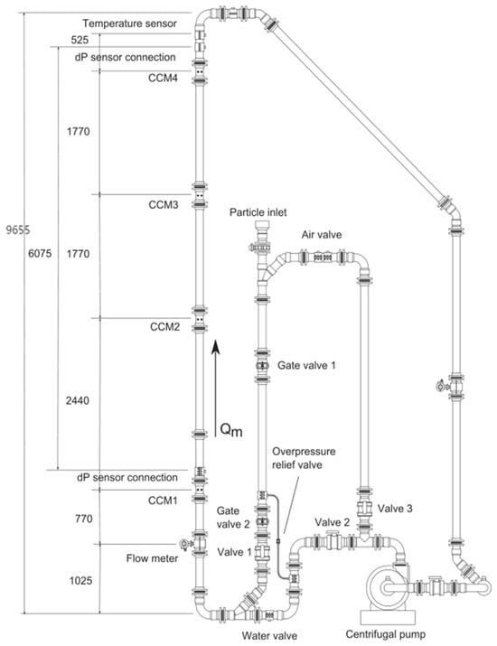
Figure 25.
Schematic diagram of the experimental setup [107].
Vortex-induced vibration in marine risers is the most critical issue in the research of marine risers. Many scholars have studied the impact of external and internal excitations. With the substantial rise in the riser’s aspect ratio, there is an escalation in the complexity of vortex-induced vibration, leading to a higher occurrence of fatigue damage on the riser [94]. With the exploitation system extending to deep-sea areas, floating platforms and hulls are increasingly applied in exploitation activities. Unlike the original fixed platform, floating platforms lead to VIV of marine risers that exhibit significant amplitudes and higher-order modes, which is very different from the vortex-induced vibration without taking into account the motion of buoyant platforms [107]. Brika and Laneville [108] conducted wind tunnel tests on moving cables and examined the oscillatory behavior of the eddy wake mode under unconstrained conditions. Chen et al. [109] studied the diffusion rules of platform horizontal movements such as swing and surge and found that platform horizontal movements interacted with vortex-induced vibration of risers, which further led to nonlinear coupling on the boundary of motion. Yin et al. [110] considered the impact of platform movement on riser vibration and found that it is stronger than the crossflow vortex-induced vibration caused by oscillating flow. Wang et al. [111] found that horizontal motion would lead to significant drag amplification at small Keulegan–Carpenter (KC) numbers. The amplitude and frequency of VIV are the result of platform motion demonstrating consistent patterns over time. Time-frequency analysis results for this scenario are depicted in Figure 26. A novel numerical approach was introduced by Wang et al. [112], demonstrating excellent accuracy in forecasting vortex-induced vibration frequency, stress levels, and amplitude through rigorous experimental validation. In contrast to lateral movement on the platform, vertical displacement predominantly impacts the riser’s dynamic tension dynamics, leading to periodic variations in its structural characteristics, which consequently gives rise to heightened risk factors associated with dynamic responses [113].
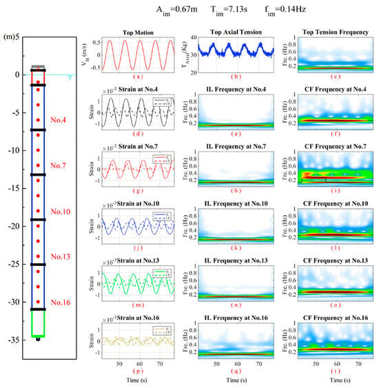
Figure 26.
Time-frequency results for the case from 41.1 s to 77.1 s ((a) top motion velocity; (b) top axial tension variation; (c) time-varying response frequency for the top tension; (d,g,j,m,p) in-plane and out-plane bending strain time histories at 5 selected stations; (e,h,k,n,q) time-varying response frequency of the in-plane responses at 5 selected stations; (f,i,l,o,r) time-varying response frequency of the out-of-plane responses at 5 selected stations) [111].
Most studies on VIV focus on external stimuli, such as fluid movement and the motion of floating platforms, while disregarding the impact of internal flow on vortex-induced vibration. When fluid flows in the riser, the mutual movement between the two will generate centrifugal force and Coriolis force. Meng et al. [114] researched the influence of centrifugal force and Coriolis force on vortex-induced vibration. Many investigations into VIV primarily concentrate on external stimuli, such as fluid movement and the motion of floating platforms, while disregarding the impact of internal flow on VIV. The variations in mass, momentum, and pressure are heightened due to the fluctuations caused by the flow velocity and volume ratio of diverse fluids, thereby amplifying the intricacy associated with VIV [115]. Thorsen et al. [116] explored the impact of internal flow on structural dynamics by using a numerical simulation method, focusing on the vortex-induced vibration response under different internal flows, indicating that the internal density wave will have a particular impact on the vortex-induced vibration of marine risers. In addition to the influence of a floating platform and internal flow, factors such as surface texture [117], choice of structural material [118], and interaction between the riser and soil in the landing zone [111] also play a significant role in influencing VIV of the riser. The polymetallic nodules transported inside the riser are not stable fluids during the transportation process but form slug flows in the riser. Meng et al. [119] conducted a study on the impact of slug flow on the VIV of a flexible riser. The simulation diagram depicting this phenomenon can be observed in Figure 27.
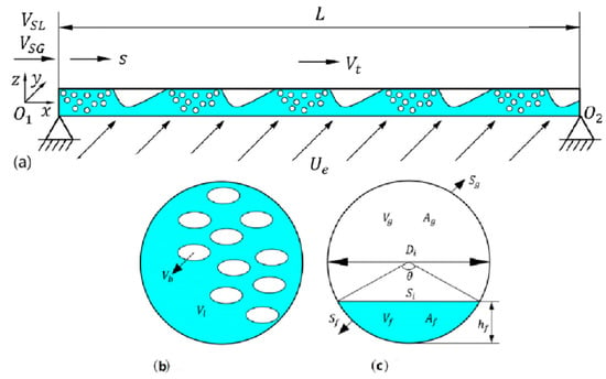
Figure 27.
Numerical simulation cross-section. (a) A horizontal flexible riser; (b) liquid slug region; (c) film zone [119].
In the domain of ocean engineering, numerous researchers have conducted investigations on techniques to mitigate vortex-induced vibration. The suppression of VIV in cylindrical structures can be achieved by utilizing the control rod as a passive mechanism. The performance of the control rods is influenced by various factors, including the number of control rods, diameter ratio, coverage, and angle of attack [120,121,122,123]. Lu et al. [124] calculated the fatigue damage assessment of the efficacy of the flexible cylinder model through the utilization of empirical measurements conducted within a controlled laboratory setting (Figure 28). Based on this premise, an investigation was conducted to analyze the fatigue lifespan of the master cylinder model equipped with varying angles of attack for either three or four control rods. The findings indicate that employing four control rods yields a more significant reduction in loss compared to using three control rods. A study showed that the control rod effectively suppresses the VIV of an ocean riser [36]. K.D et al. [125] designed a new boundary controller and developed the Lyapunov direct method for control design and stability analysis to achieve global adaptability for assessing the resilience of marine riser systems to unpredictable environmental forces.
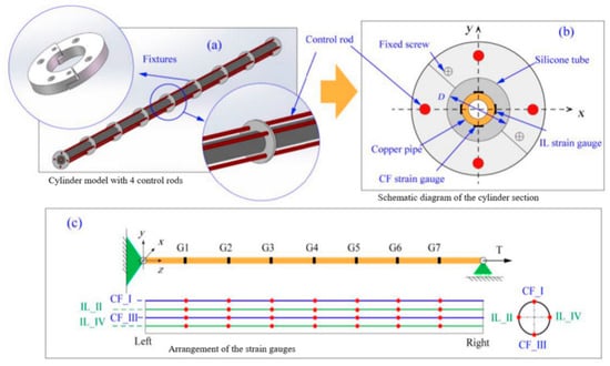
Figure 28.
A flexible cylinder model was used in the experiment. (a) Cylinder model with 4 control rods. (b) Schematie diagram of the cylinder section. (c) Arrangement of the strain gauges [124].
Although the existing research has made some progress in VIV of the riser lift pipe, there are still some shortcomings. Vortex-induced vibration is a complex fluid–structure coupling problem, and existing mathematical models may not be able to fully capture all the details of the fluid–structure interaction, especially under complex marine environmental conditions. Experimental studies are usually limited by conditions such as scale effects, and differences between the laboratory environment and the actual marine environment, and these factors may affect the extrapolation of experimental results. The effects of vortex-induced vibration on structures are usually cumulative over a long period of time, so it may be difficult to accurately predict the effects of long-term vibration on structural integrity.
6. Interconnections between the Components of a Deep-Sea Mining System
Deep-sea mining encompasses a comprehensive system that involves not only individual components but also the interplay among different underwater devices. Therefore, it is crucial to investigate the deep-sea mining system holistically rather than focusing solely on one device. This entails examining the interactions between various devices and the overall system, necessitating the development of a multi-body dynamics model accordingly.
6.1. Coupling Analysis between Each Device of the Mining Vehicle
The main devices of DSMV include a walking device and a collecting device, and the interaction between the two plays a crucial role in improving the overall collection efficiency. The moving performance of the walking device will directly affect the efficiency of collecting polymetallic nodules in the collecting device, and the vibration generated by the collecting device during the collection of polymetallic nodules will also affect the moving performance of the walking device. Therefore, it is not feasible to design individual components of the DSMV based on specific sections of the objective. This makes the design of deep-sea mining devices a multi-variable, multi-disciplinary, coupled, and nonlinear problem [126].
Cho et al. [127] conducted laboratory and shore tests on the mining vehicle, considering the dynamic performance of the caterpillar and the nonlinear performance of the collector. In order to optimize the advantages derived from global optimization to their fullest extent, a proxy model was proposed as an effective alternative to derivative-free global optimization. The research framework used is shown in Figure 29. Zhu et al. [128] studied the vibrational impact of a collecting device on diverse DSS dynamic behavior. The heterogeneity of DSS was verified by experiments, and the nonlinear increase of elastic modulus with depth was revealed. The establishment of the wave equation aims to analyze the dynamic response of DSS, which possesses a nonlinear modulus when it is subjected to loading from the collecting device. This research offers a theoretical foundation for enhancing the operational effectiveness of the ambulatory apparatus. Zhu et al. [129] developed a dynamic response model that considers the coupling of thermal, hydraulic, and mechanical factors in heterogeneous saturated porous sediments in deep-sea environments. It investigates how variations in elastic modulus, density, frequency, and load amplitude impact the model’s behavior. By employing normal modal analysis techniques, the researchers obtained a multivariate analytic solution.
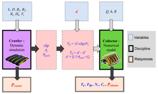
Figure 29.
Research system framework [24].
6.2. Coupling Analysis between Riser Lifting Device and Mining Vehicle
In order to study the monomer dynamics model of various deep-sea mining devices, Zou et al. [130] proposed a novel approach for modeling and controlling unmanned tracked vehicles in intricate terrains, utilizing estimation techniques for pose and torsion. Chen et al. [131] investigated the impact of bidirectional internal flow interaction dynamics on riser behavior using computational fluid dynamic simulation. Their findings revealed that computational fluid dynamic analysis plays a significant role in determining vibration and instantaneous amplitude. Adamiec et al. [132] proposed a discrete element method-based theory for analyzing the behavior of planar elongated bar systems under large deflections. A mixed finite-boundary element method was introduced by Cheng et al. [133] to investigate the nonlinear interaction between mooring risers and ship waves, and experimental validation was conducted to demonstrate the applicability of this approach.
However, the whole dynamic model and the coordinated motion control of an integrated deep-sea mining system based on a nonlinear dynamic model have not been realized. Chung et al. [134] simplified the use of nonlinear beam elements in pipelines. They developed a finite element model and used an iterative solution of the incremental Newton–Raphson method to investigate the migration characteristics of each device within a deep-sea mining system, considering various factors such as mass and subsystem connection. They also conducted a hydraulic analysis and examined the linkage of lifting pipes within the system. Y et al. [83] developed a robust and efficient nonlinear multi-body dynamic model as well as a coordinated motion control model for a deep-sea mining system. Building upon this, they successfully conducted a co-simulation of the dynamic and control models, they proposed and simulated the integrated motion model for the entire system. Chen et al. [135] developed a virtual prototype model of the deep-sea mining system and a load model of the lifting device under the marine dynamic environment based on the dynamic reaction of the riser and the DSMV under different linkage modes, and the dynamic responses among the riser, the conveying hose and the mining vehicle were analyzed. The safe and efficient operation of deep-sea mining systems and the early stage of system design and safety checks heavily rely on understanding the dynamic characteristics of the riser lifting system as well as the dynamic response exhibited by each subsystem. Liu et al. [136] investigated the impacts of longitudinal–lateral coupling, external current vortex induction, and internal fluid pulsation. They developed a nonlinear vibration model for this system by employing the finite element method, energy method, and Hamiltonian variational principle with multi-field coupling consideration, aiming at the overall vibration failure induced by riser flow. The flow chart of solving the nonlinear dynamics model is shown in Figure 30.
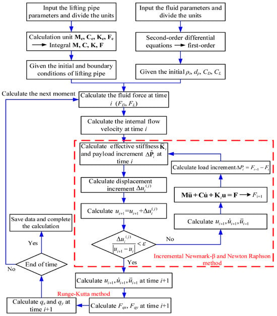
Figure 30.
Solving nonlinear dynamics model flow chart [136].
Although some studies have been carried out on the coupling analysis among various devices, there are still many shortcomings in the overall study. Due to the limitations of experimental simulation, all effective variables have not been fully considered, and there are few studies on the interaction between the whole mining system and the influence of the traveling device on the collection device. The direct influence mechanism of each device and the tradeoff relationship between the constraints are still lacking.
7. Conclusions
This paper summarized relevant articles on the latest development of underwater collection and transportation equipment of polymetallic nodules, and some typical deep-sea mining systems are summarized. The latest developments in underwater collection and transportation equipment of polymetallic nodules are introduced, including collecting devices, walking devices, and lifting devices, and a detailed analysis of different devices was carried out, respectively. Deep-sea mining systems work in high-pressure environments at a depth of 6000 m, and the efficiency assessment involves the acquisition of synthetic polymetallic nodules during sea experiments.
Recent achievements on the collecting device and the walking device of DSMV are reviewed. The microstructure and physical properties of DSS are crucial for the trafficability in soft deep-sea sediments. Considering the complexity of polymetallic nodules acquisition, the influence of different jet head structure parameters on jet acquisition efficiency is discussed. In order to adapt to fluctuation of the deep-seabed topography, a flexible hose must be installed between the lifting device and the collecting device. The flow model in a horizontal pipe of coarse particles was studied and established. Furthermore, the optimal structural parameters of the walking device are proposed, and various constitutive laws of sea soil are established in order to achieve maximum tractive force and minimum settlement. The dynamic characteristics of the DSMV in various operational scenarios were analyzed in view of the complex subsea road conditions. In order to improve the mobility and acquisition efficiency of DSMV, the lightweight design of different materials was proposed.
It was concluded that the lifting pump and riser are crucial for the deep-sea mining lifting device. The optimal lifting pump structure was established to effectively diminish hydraulic friction losses and obstructions. The internal working mechanism behind the deterioration process caused by friction and blockage in complex channels was investigated. The vortex-induced vibration response model of the riser under internal and external excitation was established to show key factors affecting the stability of the riser.
The interaction between the deep-sea mining devices was summarized, and the nonlinear and dynamic coupling model between the devices was established by setting up the finite element model and considering the linkage between the devices. This is essential to consider the efficiency of deep-sea mining systems as a whole.
In order to ensure the commercial exploitation of polymetallic nodules, there are still some key problems to be solved in the existing deep-sea mining research. First of all, deep-sea mining will have a huge impact on the marine environment, and there needs to be a full balance between ecological and commercial relations. Secondly, due to the limitation of experimental simulation, all effective variables were not fully considered in optimizing the mining efficiency of each device. Thirdly, there are few studies on the interaction between the various devices in deep-sea mining. Finally, the direct influence mechanism of each device and the tradeoff relationship between the constraints are still lacking.
Author Contributions
X.Z.: Data curation, writing—review and editing, funding; Y.Z.: investigation, data curation, writing—original draft; J.W.: methodology writing—review and editing, investigation; F.S.: Conceptualization, supervision, methodology, funding acquisition, writing—review and editing; Z.Y.: writing, suggestion, organization; X.L.: writing, suggestion, organization; M.X.: writing, suggestion, organization; J.X.: writing, methodology, suggestion. All authors have read and agreed to the published version of the manuscript.
Funding
The content of this work was sponsored from National Natural Science Foundation of China (51909140), Shandong Provincial University Youth Innovation Science and Technology Support Program (2021KJ034) the Young Talent Program of Ocean University of China (862101013168), and Deep-sea Mining Technology Equipment Technology System and Patent Layout ResearchProject (CMMI-E-1-2021-005).
Data Availability Statement
No applicable.
Conflicts of Interest
As author Xiuzhan Zhang, Jiakang Wei, Zhenqin Yuan was employed by the company China Merchants Marine and Offshore Research Institute Co., Ltd. and China Merchants Deepsea Research Institute (Sanya) Co., Ltd. The remaining authors declare that the research was conducted in the absence of any commercial or financial relationships that could be construed as a potential conflict of interest.
References
- Amudha, K.; Reshma, K.V.; Ramesh, N.R.; Deepak, C.R.; Ramadass, G.A.; Atmanand, M.A. Estimation of sinkage and breakout forces for tracked vehicle for soft soils. In Proceedings of the OCEANS 2014—TAIPEI, Taipei, Taiwan, 7–10 April 2014. [Google Scholar]
- Leng, D.; Shao, S.; Xie, Y.; Wang, H.; Liu, G. A brief review of recent progress on deep sea mining vehicle. Ocean Eng. 2021, 228, 108565. [Google Scholar] [CrossRef]
- Teague, J.; Allen, M.J.; Scott, T.B. The potential of low-cost ROV for use in deep-sea mineral, ore prospecting and monitoring. Ocean Eng. 2018, 147, 333–339. [Google Scholar] [CrossRef]
- Kang, Y.; Liu, S.; Zou, W.; Zhao, H.; Hu, X. Design and analysis of an innovative deep-sea lifting motor pump. Appl. Ocean Res. 2019, 82, 22–31. [Google Scholar] [CrossRef]
- Wei, D.; Cao, H.; Xia, J. Study on the pressure–sinkage process and constitutive model of Deep-Sea sediment. J. Mar. Sci. Eng. 2022, 10, 883. [Google Scholar] [CrossRef]
- He, G.; Yang, Y.; Wei, Z.; Yang, S.; Liu, Y.; Deng, X.; Yao, H.; Deng, Y.; Gao, J.; Fang, N.; et al. Mineral deposit characteristics of cobalt-rich Fe-Mn crusts in COMRA contract area. West. Pac. Ocean Chin. J. Nonferrous Met. 2021, 31, 2649–2664. [Google Scholar]
- Guo, X.; Fan, N.; Liu, Y.; Liu, X.; Wang, Z.; Xie, X.; Jia, Y. Deep seabed mining: Frontiers in engineering geology and environment. Int. J. Coal Sci. Technol. 2023, 10, 23. [Google Scholar] [CrossRef]
- Hein, J.R.; Mizell, K.; Koschinsky, A.; Conrad, T.A. Deep-ocean mineral deposits as a source of critical metals for high- and green-technology applications: Comparison with land-based resources. Ore Geol. 2013, 51, 1–14. [Google Scholar] [CrossRef]
- Wu, Q.; Yang, J.; Guo, X.; Liu, L.; Lu, W.; Lu, H. Experimental study on dynamic responses of a deep-sea mining system. Ocean Eng. 2022, 248, 110675. [Google Scholar] [CrossRef]
- Sha, F.; Xi, M.; Chen, X.; Liu, X.; Niu, H.; Zuo, Y. A recent review on multi-physics coupling between deep-sea mining equipment and marine sediment. Ocean Eng. 2023, 276, 114229. [Google Scholar] [CrossRef]
- Masuda, Y.; Cruickshank, M.J.; Mero, J.L. Continuous bucket-line dredging at 12,000 feet. In Proceedings of the Annual Offshore Technology Conference, Houston, TX, USA, 19–21 April 1971; pp. 837–841. [Google Scholar]
- Rajesh, S.; Gnanaraj, A.A.; Velmurugan, A.; Ramesh, R.; Muthuvel, P.; Babu, M.K.; Ramesh, N.R.; Deepak, C.R.; Atmanand, M.A. Qualification Tests on Underwater Mining System with Manganese Nodule Collection and Crushing Devices. In Proceedings of the Ninth ISOPE Ocean Mining Symposium, Maui, HI, USA, 19–24 June 2011; pp. 110–115. [Google Scholar]
- Sharma, R. Deep-Sea Mining: Resource Potential, Technical and Environmental Considerations; Springer: Cham, Switzerland, 2017; pp. 310–313. [Google Scholar] [CrossRef]
- Wu, Q.; Yang, J.; Lu, H.; Lu, W.; Liu, L. Effects of heave motion on the dynamic performance of vertical transport system for deep sea mining. Ocean Res. 2020, 101, 102188. [Google Scholar] [CrossRef]
- Kang, Y.; Liu, S. Summary of research on lifting system of Deep Sea mining. J. Mech. Eng. 2021, 57, 232–243. [Google Scholar]
- Qiao, S.; Wu, Y.; Zhu, Z.; Qing, L.; Huang, Z.; Ning, Q. Effects of confining pressure and cutting sequence on the cobalt-rich crust cutting mechanism by using conical picks in ocean environments. Ocean Eng. 2022, 263, 112348. [Google Scholar] [CrossRef]
- Li, J.P.; Rao, Q.H.; Huang, T.B.; Ma, W.B. Discrete element method for adhesion properties evaluation of deep-sea sediment from macro and micro perspectives. J. Cent. South Univ. 2022, 29, 1701–1716. [Google Scholar] [CrossRef]
- Sha, F.; Xi, M.; Wen, Z.; Chen, X.; Zuo, Y.; Xu, J.; Zhang, M.; Niu, H. A review on plumes generation and evolution mechanism during deep-sea polymetallic nodules mining. Ocean Eng. 2024, 298, 117188. [Google Scholar] [CrossRef]
- Spearman, J.; Taylor, J.; Crossouard, N.; Cooper, A.; Turnbull, M.; Manning, A.; Lee, M.; Murton, B. Measurement and modelling of deep sea sediment plumes and implications for deep sea mining. Sci. Rep. 2020, 10, 5075. [Google Scholar] [CrossRef]
- Wang, M. The Development of Deep Seafloor Solid Mineral Resources; Central South University Press: Changsha, China, 2015. [Google Scholar]
- American Bureau of Shipping Guide for Subsea Mining. 2020, pp. 16–17. Available online: https://ww2.eagle.org/en/Products-and-Services/offshore-energy/subsea-mining.html (accessed on 18 February 2024).
- Gollner, S.; Kaiser, S.; Menzel, L.; Jones, D.O.; Brown, A.; Mestre, N.C.; Van Oevelen, D.; Menot, L.; Colaço, A.; Canals, M. Resilience of benthic deep-sea fauna to mining activities. Mar. Environ. Res. 2017, 129, 76–101. [Google Scholar] [CrossRef]
- Nian, T.K.; Jiao, H.B.; Fan, N.; Guo, X.S. Microstructure analysis on the dynamic behavior of marine clay in the South China Sea. Mar. Georesour. Geotechnol. 2019, 38, 349–362. [Google Scholar] [CrossRef]
- Cho, S.G.; Park, S.; Oh, J.; Min, C.; Kim, H.; Hong, S.; Jang, J.; Lee, T.H. Design optimization of deep-seabed pilot miner system with coupled relations between constraints. J. Terramech. 2019, 83, 25–34. [Google Scholar] [CrossRef]
- Khadge, N.H. Geotechnical properties of surface sediments in the INDEX area. Georesour. Geotechnol. 2000, 18, 251–258. [Google Scholar] [CrossRef]
- Rao, Q.; Liu, Z.; Xu, F.; Huang, W.; Ma, W. Research progress on characteristics of Deep-sea soft sediment and walking performance of mining vehicle. Chin. J. Nonferrous Met. 2021, 31, 2795–2816. [Google Scholar]
- Yu, Y.; Duan, L.; Wang, H.; Du, X.; Zhu, K. Preliminary study on physico-mechanical properties of Deep-sea sediments from the western pacific. Min. Metall. Eng. 2016, 36, 1–4. [Google Scholar]
- Wei, D.; Yang, Q.; Xia, J. Factors influencing shear strength of deep sediment and its variation law. Mar. Geol. Front. 2021, 37, 28–33. [Google Scholar]
- Washburn, T.W.; Jones, D.O.B.; Wei, C.-L.; Smith, C.R. Environmental heterogeneity throughout the clarion-clipperton zone and the potential representativity of the APEI network. Front. Mar. Sci. 2021, 8, 661685. [Google Scholar] [CrossRef]
- Ma, W.B.; Rao, Q.H.; Li, P.; Guo, S.C.; Feng, K. Shear creep parameters of simulative soil for deep-sea sediment. J. Cent. South Univ. 2014, 21, 4682–4689. [Google Scholar] [CrossRef]
- Suneel, M.; Park, L.K.; Im, J.C. Compressibility characteristics of Korean marine clay. Mar. Georesour. Geotechnol. 2008, 26, 111–127. [Google Scholar] [CrossRef]
- Li, D.; Fu, Y.; Liu, Q.; Reinfelder, J.R.; Hollings, P.; Sun, X.; Tan, C.; Dong, Y.; Ma, W. High-resolution LA-ICP-MS mapping of deep-sea polymetallic micronodules and its implications on element mobility. Gondwana Res. 2020, 81, 461–474. [Google Scholar] [CrossRef]
- Dai, X.; Shan, R.; Kong, X.; Yang, N.; Sun, S. Preliminary study on physical properties and microstructure of deep-sea sediments from Marianas Trench. Ocean Eng. 2019, 37, 150–156. [Google Scholar]
- Wu, H.; Chen, X.; Gao, Y.; He, J.; Liu, S. In-situ shearing strength and penetration resistance testing of soft seabed sediments in western mining area. J. Cent. South Univ. 2010, 41, 1801–1806. [Google Scholar]
- Choi, J.S.; Hong, S.; Chi, S.B.; Lee, H.B.; Park, C.K.; Kim, H.W.; Yeu, T.K.; Lee, T.H. Probability distribution for the shear strength of seafloor sediment in the KR5 area for the development of manganese nodule miner. Ocean Eng. 2011, 38, 2033–2041. [Google Scholar] [CrossRef]
- Luo, M.; Chen, P.; Chen, Z. Experimental investigation on the suppression of vortex-nduced vibration of two interfering risers by control rods. Ships Offshore Struct. 2017, 12, 1117–1126. [Google Scholar]
- Sung, J.L.; Jong, W.K.; Shin, T.J.; Hong, Y.C.; Sang, H.L. Deep Seawater flow Characteristics Around the Manganese Nodule Collecting Device. Procedia Eng. 2015, 116, 544–551. [Google Scholar] [CrossRef]
- Kartal, V.; Emiroglu, M.E. Effect of nozzle type on local scour in water jets: An experimental study. Ocean Eng. 2023, 277, 114323. [Google Scholar] [CrossRef]
- Wang, P.J.; Li, L.; Wu, J.B. Research on the lightweight structural optimization design of the front collector of the polymetallic nodule miner. Ocean Eng. 2023, 267, 113275. [Google Scholar] [CrossRef]
- Rouse, H. Criteria for Similarity in the Transportation of Sediment; Iowa Institute of Hydroscience & Engineering University of Iowa: Iowa City, IA, USA, 1939; pp. 33–49. [Google Scholar]
- Tastan, K.; Kocak, P.P.; Yildirim, N. Effect of the bed-sediment layer on the scour caused by a jet. Arab. J. Sci. Eng. 2016, 41, 4029–4037. [Google Scholar] [CrossRef]
- Baylar, A.; Emiroglu, M.E. Air entrainment and oxygen transfer in a Venturi. Proc. Inst. Civ. Eng.-Water Marit. Eng. 2003, 156, 249–255. [Google Scholar] [CrossRef]
- Zhang, T.D.; Zhou, H.; Wang, J.; Liu, Z.H.; Xin, J.; Pang, Y.J. Optimum design of a small intelligent ocean exploration underwater vehicle. Ocean Eng. 2019, 184, 40–58. [Google Scholar] [CrossRef]
- Kartal, V.; Emiroglu, M.E. Local scour due to water jet from a nozzle with plates. Acta Geophys. 2021, 69, 95–112. [Google Scholar] [CrossRef]
- Wang, J.J. Numerical Analysis of the Effect of Nozzle on Injector Performance; Northeastern University: Shenyang, China, 2014; pp. 32–59. [Google Scholar]
- Yao, C.; Geng, P.; Yin, Z.-H.; Hu, J.; Yang, Z.-M.; Chen, D.-L. Effect of nozzle structure on spray characteristics. J. Intern. Combust. Engines 2016, 34, 41–47. [Google Scholar]
- Shi, H.H.; Zhang, Y.B.; Yin, Z.H. Numerical simulation of high-pressure pulsed water jet under different nozzle structures. J. Zhejiang Sci-Tech Univ. (Nat. Sci. Ed.) 2021, 45, 343–350. [Google Scholar]
- Asakura, K.; Asari, T.; Nakajima, I. Simulation of Solid-Liquid Flows in Vertical Pipe by a Collision Model. Powder Technol. 1997, 145, 201–209. [Google Scholar] [CrossRef]
- Ye, J.; Xia, J.X. Study on resistance loss of coarse-grained materials in horizontal pipeline hydraulics. Met. Mines 2011, 7, 12–18. [Google Scholar]
- Zhou, M.; Wang, S.; Kuang, S.; Luo, K.; Fan, J.; Yu, A. CFD-DEM modelling of hydraulic conveying of solid particles in a vertical pipe. Powder Technol. 2019, 354, 893–905. [Google Scholar] [CrossRef]
- Zhou, M.; Kuang, S.; Luo, K.; Zou, R.; Wang, S.; Yu, A. Modeling and analysis of flow regimes in hydraulic conveying of coarse particles. Powder Technol. 2020, 373, 543–554. [Google Scholar] [CrossRef]
- Cao, B.; Liu, J.W.; Xia, J.X. Study on the law of hydraulic transport resistance loss of horizontal hose in deep-sea mining system. J. Mar. Technol. 2016, 35, 114–119. [Google Scholar]
- Avi, U.; Avi, L. Flow characteristics of coarse particles in horizontal hydraulic conveying. Powder Technol. 2018, 326, 302–321. [Google Scholar] [CrossRef]
- Miller, K.A.; Thompson, K.F.; Johnston, P.; Santillo, D. An overview of seabed mining including the current state of development, environmental impacts, and knowledge gaps. Front. Mar. Sci. 2018, 4, 312755. [Google Scholar] [CrossRef]
- Cai, Q.; Ma, W.; Rao, Q.; Li, G. Optimization design of bionic grousers for the crawled mineral collector based on the deep-sea sediment. Mar. Georesour. Geotechnol. 2020, 38, 48–56. [Google Scholar] [CrossRef]
- Ma, W.B.; Liu, J.; Cheng, Y.R.; Zhu, W. Study on mesoscopic adhesion characteristics of deep-sea sediment for self-cleaning mechanism of bionic grouser. Appl. Ocean Res. 2023, 131, 103451. [Google Scholar] [CrossRef]
- Bekker, M.G. Introduction to Terrain-Vehicle Systems; University of Michigan Press: Ann Arbor, MI, USA, 1969. [Google Scholar]
- Schulte, E.; Schwarz, W. Simulation of tracked vehicle performance on deep sea soil based on soil mechanical laboratory measurements in bentonite soil. In Proceedings of the Eighth ISOPE Ocean Mining Symposium, Chennai, India, 20–24 September 2009. [Google Scholar]
- Li, L.; Li, S. Imulation and mechanical characteristics of terramechanics of the surface soil on Deep-Sea bed. Eng. Mech. 2010, 27, 213–220. [Google Scholar]
- Wang, J.; Cao, W.; Zhai, Y. Experimental study of interaction between deep-sea sediments and tracks. Rock Soil Mech. 2011, 32, 274–278. [Google Scholar]
- Wang, L.; Chen, X.; Li, Z.; Liu, X.; Liu, X.; Wang, L.; Yang, W. Analysis of traction performance of deep-sea tracked mining vehicles under different grouser pitch-to-height ratios and traveling speeds. Ocean Eng. 2024, 297, 117112. [Google Scholar] [CrossRef]
- Xu, F.; Rao, Q.-h.; Ma, W.-b. Turning traction force of tracked mining vehicle based on rheological property of deep-sea sediment. Trans. Nonferrous Met. Soc. China 2018, 28, 1233–1240. [Google Scholar] [CrossRef]
- Xu, F.; Rao, Q.-H.; Zhang, J.; Ma, W. Compression–shear coupling rheological constitutive model of the deep-sea sediment. Mar. Georesour. Geotechnol. 2018, 36, 288–296. [Google Scholar] [CrossRef]
- Zhang, N.; Ma, N.; Yin, S.; Chen, X.; Zhao, M. Three-dimensional stress path in deep-sea sediment under the driving load of a nodule collector. Ocean Eng. 2022, 253, 111312. [Google Scholar] [CrossRef]
- Hong, S.; Choi, J.S. Experimental Study on Grouser Shape Effects on Trafficability of Extremely Soft Seabed. J. Electroanal. Chem. 2001, 361, 57–63. [Google Scholar]
- Kim, H.W.; Hong, S.; Choi, J.S.; Lee, T.H. An experimental study on tractive performanceof tracked vehicle on cohesive Soft soil. In Proceedings of the Fifth ISOPE Ocean Mining Symposium, Tsukuba, Japan, 15–19 September 2003; pp. 139–143. [Google Scholar]
- Sung-Ha, B.; Gyu-Beom, S.; Choong-Ki, C. Experimental study on the soil thrust of underwater tracked vehicles moving on the clay seafloor. Appl. Ocean Res. 2019, 86, 117–127. [Google Scholar]
- Luan, L.; Chen, X.; Kouretzis, G.; Ding, X. Dynamic seabed stresses due to moving deep-sea mining vehicles. Comput. Geotech. 2023, 157, 105356. [Google Scholar] [CrossRef]
- Xu, Z.; Liu, Y.; Yang, G.; Xia, J.; Dou, Z.; Meng, Q.; Xu, X. Research on contact model of track-soft sediment and traction performance of four-tracked seabed mining vehicle. Ocean Eng. 2022, 259, 111902. [Google Scholar] [CrossRef]
- Yong, R.N.; Youssef, A.F.; El-Mamlouk, H. Soil deformation and slip relative to grouser shape and spacing. J. Terramech. 1978, 15, 129–144. [Google Scholar] [CrossRef]
- Wang, X.L.; Ito, N.; Kito, K. Studies on grouser shoe dimension for optimum tractive performance (Part 2) effect on thrust: Rolling resistance and traction. J. Jpn. Soc. Agric. Mach. 2002, 64, 55–60. [Google Scholar]
- Li, J.; Liu, S.; Dai, Y. Effect of grouser height on tractive performance of tracked mining vehicle. J. Braz. Soc. Mech. Sci. Eng. 2017, 39, 2459–2466. [Google Scholar] [CrossRef]
- Li, Y.; He, D.; Si, Q.; Meng, X. Effect of track shoes structural parameters on traction performance of unmanned underwater tracked bulldozer. Ocean Eng. 2021, 237, 109655. [Google Scholar] [CrossRef]
- Janarthanan, C.; Gopkumar, K.; Sundaramoorthi, V.; Ramesh, N.R.; Ramadass, G.A. Influence of grouser geometrical parameters of Deep-Sea crawler vehicle on soft clays. In Proceedings of the Fourth International Conference in Ocean Engineering (ICOE2018); Springer: Singapore, 2019; pp. 899–912. [Google Scholar]
- Sun, P.; Lu, H.; Yang, J.; Liu, M.; Li, S.; Zhang, B. Numerical study on shear interaction between the track plate of deep-sea mining vehicle and the seafloor sediment based on CEL method. Ocean Eng. 2022, 266, 112785. [Google Scholar] [CrossRef]
- Xu, W.; Ji, C.; Sun, H.; Ding, W.; Bernitsas, M.M. Flow induced vibration of two elastically mounted tandem cylinders in cross-flow at subcritical Reynolds numbers. Ocean Eng. 2019, 173, 375–387. [Google Scholar] [CrossRef]
- Li, J.; Kou, B.; Liu, G.; Fan, W.; Liu, L. Resistance reduction by bionic coupling of the earthworm lubrication function. Sci. China 2010, 53, 2989–2995. [Google Scholar] [CrossRef]
- Ren, L. Progress in the bionic study on anti-adhesion and resistance reduction of terrain machines. Sci. China Ser. E Technol. Sci. 2009, 52, 273–284. [Google Scholar] [CrossRef]
- Dai, Y.; Xue, C.; Su, Q.; Huang, X. Numerical analysis on hydrodynamic characteristics of a deep-sea mining vehicle under three typical motions. Ocean Eng. 2021, 235, 109446. [Google Scholar] [CrossRef]
- Baek, S.H.; Shin, G.B.; Chung, C.K. Assessment of the side thrust for off-road tracked vehicles based on the punching shear theory. J. Terramech. 2018, 79, 59–68. [Google Scholar] [CrossRef]
- Zhang, T.; Dai, Y.; Liu, S.; Chen, J.; Huang, Z. Multi-body dynamic modeling and mobility simulation analysis of deep ocean tracked miner. J. Mech. Eng. 2015, 51, 173–180. [Google Scholar] [CrossRef]
- Dai, Y.; Zhu, X.; Chen, L.S.; Liu, H. A new multi-body dynamic model for seafloor miner and its trafficability evaluation. Int. J. Simulat. Model. 2015, 14, 732–743. [Google Scholar] [CrossRef]
- Dai, Y.; Yin, W.; Ma, F. Nonlinear multi-body dynamic modeling and coordinated motion control simulation of deep-sea mining system. IEEE Access 2019, 7, 86242–86251. [Google Scholar] [CrossRef]
- Ouyang, H.; Wang, S.P. Slip control for deep sea mining vehicle: Sliding mode control approach. In Proceedings of the 2016 35th Chinese Control Conference (CCC), Chengdu, China, 27–29 July 2016; pp. 6233–6238. [Google Scholar] [CrossRef]
- Sumith, S.; Sangam, K.; Kannan, K.; Shankar, K. Prediction of nonlinear viscoelastic behaviour of simulative soil for deep-sea sediment using a thermodynamically compatible model. Inverse Probl. Sci. Eng. 2020, 28, 777–795. [Google Scholar] [CrossRef]
- Kang, J.I.; Jeoung, S.K.; Oh, J.Y.; Choi, H.S.; Kim, Y.H.; Kim, J.Y.; Yu, S.H.; Cho, H.K. An analysis of carbon fiber hull structure of a new underwater glider. Int. J. Mod. Phys. B 2018, 32, 1840065. [Google Scholar] [CrossRef]
- Li, B.; Pang, Y.J.; Zhu, X.M.; Cheng, Y.X. Collaborative optimization and 6 sigma design for composite pressure hull of underwater vehicle based on lamination parameters. J. Mar. Sci. Technol. 2018, 23, 557–566. [Google Scholar] [CrossRef]
- Li, N.; Zhang, D.Q.; Liu, H.T.; Li, T.J. Optimal design and strength reliability analysis of pressure shell with grid sandwich structure. Ocean Eng. 2021, 223, 108657. [Google Scholar] [CrossRef]
- Yang, H.; Liu, S. A new lifting pump for deep-sea mining. J. Mar. Eng. Technol. 2020, 19, 102–108. [Google Scholar] [CrossRef]
- Li, W.; Shi, W.; Jiang, X.; Zhou, L.; Xu, Y.; Jiang, Z. Numerical calculation and experimental study of axial force on multistage centrifugal pump. Trans. Chin. Soc. Agric. Eng. 2012, 28, 52–59. [Google Scholar] [CrossRef]
- Zhou, L.; Shi, W.; Lu, W.; Li, Z.; Li, W. Numerical prediction and experiment of axial force on deep-well centrifugal pump. Trans. Chin. Soc. Agric. Mach. 2012, 43, 100–103. [Google Scholar] [CrossRef]
- Wang, R.; Zhu, Z.; Su, X.; Mianowicz, K.; Jia, H.; Wu, K. Slurry pumps in deep-sea mining: A review of numerical and experimental studies. Ocean Eng. 2022, 251, 111150. [Google Scholar] [CrossRef]
- Wu, N.; Zhang, Q.; Qu, Z.Q. Evaluation on calculation methods of solid particle settling velocity in fluid. Oil Drill. Prod. Technol. 2000, 22, 51–53. [Google Scholar]
- Liu, G.; Li, H.; Qiu, Z.; Leng, D.; Li, Z.; Li, W. A mini review of recent progress on vortex-induced vibrations of marine risers. Ocean Eng. 2020, 195, 106704. [Google Scholar] [CrossRef]
- Talmon, A.M.; Van Rhee, C. Test set-up for irregular vertical hydraulic transport in deep ocean mining. In Proceedings of the ASME 30th International Conference on Ocean, Offshore and Arctic Engineering, Rotterdam, The Netherlands, 19–24 June 2011. [Google Scholar]
- Kang, Y.; Su, Q.; Liu, S. On the axial thrust and hydraulic performance of a multistage lifting pump for deep-sea mining. Ocean Eng. 2022, 265, 112534. [Google Scholar] [CrossRef]
- Xia, B.; Kong, F.; Zhang, H.; Yang, L.; Qian, W. Investigation of axial thrust deviation between the theory and experiment for high-speed mine submersible pump. Adv. Mech. Eng. 2018, 10, 11–12. [Google Scholar] [CrossRef]
- Badr, H.M.; Ahmed, W.H. Axial and radial thrusts in centrifugal pumps. In Pumping Machinery Theory and Practice; John Wiley & Sons, Ltd.: Hoboken, NJ, USA, 2014; pp. 133–158. [Google Scholar] [CrossRef]
- Cao, W.; Dai, X.; Hu, Q. Effect of impeller reflux balance holes on pressure and axial force of centrifugal pump. J. Cent. South Univ. 2015, 22, 1695–1706. [Google Scholar] [CrossRef]
- Elicio, G.; Annese, F. Experimental approach to predict the residual axial thrust in centrifugal pumps. In Proceedings of the ASME-JSME-KSME 2019 8th Joint Fluids Engineering Conference. Volume 3B: Fluid Applications and Systems, San Francisco, CA, USA, 28 July–1 August 2019. [Google Scholar] [CrossRef]
- Mou, J.; Li, S.; Zheng, S.; Jin, J.; Su, M.; Zhao, Y. Influence of interstage leakage on the axial force of the multistage centrifugal pump. Trans. Chin. Soc. Agric. Mach. 2010, 41, 40–44. [Google Scholar] [CrossRef]
- Li, R.; Gao, Y.; Cheng, X.; Han, W.; Guo, W. Numerical calculation for effects of impeller back pump-out vanes on axial thrust in screw centrifugal pump. J. Mech. Eng. 2012, 48, 156–161. [Google Scholar] [CrossRef]
- Babayigit, O.; Ozgoren, M.; Aksoy, M.H.; Kocaaslan, O. The effect of balance holes to centrifugal pump performance. In Proceedings of the International Conference on Numerical Analysis and Applied Mathematics, Rhodes, Greece, 19–25 September 2016; AIP Conference Proceedings; Simos, T., Tsitouras, C., Eds.; AIP Publishing: Melville, NY, USA, 2017; Volume 1863. [Google Scholar] [CrossRef]
- Zhu, D.; Xiao, R.; Yao, Z.; Yang, W.; Liu, W. Optimization design for reducing the axial force of a vaned mixed-flow pump. Eng. Appl. Comput. Fluid Mech. 2020, 14, 882–896. [Google Scholar] [CrossRef]
- Evans, J.; Shook, C.A. Dispersion and slip effects in hydraulic hoisting of solids. Can. J. Chem. Eng. 1991, 69, 166–1173. [Google Scholar] [CrossRef]
- Van Wijk, J.M.; Van Rhee, C.; Talmon, A.M. Axial dispersion of suspended sediments in vertical upward pipe flow. Ocean Eng. 2014, 92, 20–30. [Google Scholar] [CrossRef]
- Chen, W.L.; Zhang, Q.; Li, H.; Hu, H. An experimental investigation on vortex induced vibration of a flexible inclined cable under a shear flow. J. Fluids Struct. 2015, 54, 297–311. [Google Scholar] [CrossRef]
- Brika, D.; Laneville, A. Vortex-induced vibrations of a long flexible circular cylinder. J. Fluid Mech. 1993, 250, 481–508. [Google Scholar] [CrossRef]
- Chen, W.L.; Ji, C.; Xu, W.; Liu, S.; Campbell, J. Response and wake patterns of two side-by-side elastically supported circular cylinders in uniform laminar cross-flow. J. Fluids Struct. 2015, 55, 218–236. [Google Scholar] [CrossRef]
- Yin, D.; Passano, E.; Lie, H.; Grytøyr, G.; Aronsen, K.; Tognarelli, M.; Kebadze, E.B. Experimental and numerical study of a top tensioned riser subjected to vessel motion. Ocean Eng. 2019, 171, 565–574. [Google Scholar] [CrossRef]
- Wang, J.; Xiang, S.; Fu, S.; Cao, P.; Yang, J.; He, J. Experimental investigation on the dynamic responses of a free-hanging water intake riser under vessel motion. Mar. Struct. 2016, 50, 1–19. [Google Scholar] [CrossRef]
- Wang, E.; Xu, W.; Yu, Y.; Zhou, L.; Incecik, A. Flow-induced vibrations of three and four long flexible cylinders in tandem arrangement: An experimental study. Ocean Eng. 2019, 178, 170–184. [Google Scholar] [CrossRef]
- Kuiper, G.L.; Brugmans, J.; Metrikine, A.V. Destabilization of deep-water risers by a heaving platform. J. Sound Vib. 2008, 310, 541–557. [Google Scholar] [CrossRef]
- Meng, S.; Song, S.; Che, C.; Zhang, W. Internal flow effect on the parametric instability of deepwater drilling risers. Ocean Eng. 2018, 149, 305–312. [Google Scholar] [CrossRef]
- Montoya-Hernández, D.J.; Vázquez-Hernández, A.O.; Cuamatzi, R.; Hernandez, M.A. Natural frequency analysis of a marine riser considering multiphase internal flow behavior. Ocean Eng. 2014, 92, 103–113. [Google Scholar] [CrossRef]
- Thorsen, M.J.; Challabotla, N.R.; Sævik, S.; Nydal, O.J. A numerical study on vortex-induced vibrations and the effect of slurry density variations on fatigue of ocean mining risers. Ocean Eng. 2019, 174, 1–13. [Google Scholar] [CrossRef]
- Gao, Y.; Fu, S.; Wang, J.; Song, L.; Chen, Y. Experimental study of the effects of surface roughness on the vortex-induced vibration response of a flexible cylinder. Ocean Eng. 2015, 103, 40–54. [Google Scholar] [CrossRef]
- Xue, H.; Tang, W.; Qu, X. Prediction and analysis of fatigue damage due to cross- flow and in-line VIV for marine risers in non-uniform current. Ocean Eng. 2014, 83, 52–62. [Google Scholar] [CrossRef]
- Meng, S.; Chen, Y.; Che, C. Slug flow’s intermittent feature affects VIV responses of flexible marine risers. Ocean Eng. 2020, 205, 106883. [Google Scholar] [CrossRef]
- Wu, H.; Sun, D.P.; Lu, L.; Teng, B.; Tang, G.Q.; Song, J.N. Influence of attack angle on VIV suppression by multiple control rods for long flexible riser model. In Proceedings of the 21st International Offshore and Polar Engineering Conference, Maui, HI, USA, 19–24 June 2011; pp. 1276–1283. [Google Scholar]
- Wu, H.; Sun, D.P.; Lu, L.; Teng, B.; Tang, G.Q.; Song, J.N. Experimental investigation on the suppression of vortex-induced vibration of long flexible riser by multiple control rods. J. Fluid Struct. 2012, 30, 115–132. [Google Scholar] [CrossRef]
- Zhu, H.; Gao, Y. Effect of gap on the vortex-induced vibration suppression of a circular cylinder using two rotating rods. Ships Offshore Struct. 2018, 13, 119–131. [Google Scholar] [CrossRef]
- Xu, F.; Rao, Q.; Ma, W. Track Shoe Structure Optimization of Deep-Sea Mining Vehicle Based on New Rheological Calculation Formulae of Sediment. Mech. Based Des. Struct. Mach. 2019, 47, 479–496. [Google Scholar] [CrossRef]
- Lu, Y.; Liao, Y.; Xu, W. An investigation into the fatigue damage of a long flexible cylinder with multiple control rods in crossflow. Ocean Eng. 2020, 202, 107175. [Google Scholar] [CrossRef]
- Do, K.D. Boundary control of transverse motion of flexible marine risers under stochastic loads. Ocean Eng. 2018, 155, 156–172. [Google Scholar] [CrossRef]
- Lee, M.; Cho, S.; Choi, J.S.; Kim, H.W.; Hong, S.; Lee, T.H. Metamodel-based multidisciplinary design optimization of a deep-sea manganese nodules test miner. J. Appl. Math. 2012, 2012, 326954. [Google Scholar] [CrossRef]
- Cho, S.G.; Park, S.; Oh, J.; Min, C.; Kim, S.; Kim, H.W.; Yeu, K.T.; Jung, J.Y.; Bae, J.; Hong, S. Risk-based design of on-board facility for lifting system field test of deep-sea mining system. J. Ocean Eng. Technol. 2016, 30, 526–534. [Google Scholar] [CrossRef][Green Version]
- Zhu, W.; Pan, J.; Ma, W.; Deng, S.; Zhou, W.; Liu, W.; Long, S.; Yang, C.; You, L. Dynamic response of the heterogeneous deep-sea sediment with nonlinear gradient modulus to mining machine loading. Mar. Georesour. Geotechnol. 2022, 40, 255–266. [Google Scholar] [CrossRef]
- Zhu, W.; Ma, X.; Shi, X.; Ma, W. Dynamic coupled thermo-hydro-mechanical problem for heterogeneous deep-sea sediments under vibration of mining vehicle. Appl. Math. Mech. 2023, 44, 603–622. [Google Scholar] [CrossRef]
- Zou, T.; Angeles, J.; Hassani, F. Dynamic modeling and trajectory tracking control of unmanned tracked vehicles. Robot. Auton. Syst. 2018, 110, 102–111. [Google Scholar] [CrossRef]
- Chen, Z.S.; Kim, W.J. Effect of bidirectional internal flow on fluid–structure interaction dynamics of conveying marine riser model subjectto shear current. Int. J. Nav. Archit. Ocean Eng. 2012, 4, 57–70. [Google Scholar]
- Adamiec-Wójcik, I.; Brzozowska, L.; Drąg, Ł. An analysis of dynamics of risers during vessel motion by means of the rigid finite element method. Ocean Eng. 2015, 106, 102–114. [Google Scholar] [CrossRef]
- Cheng, Y.; Ji, C.; Zhai, G.; Oleg, G. Nonlinear analysis for ship-generated waves interaction with mooring line/riser systems. Mar. Struct. 2018, 59, 1–24. [Google Scholar] [CrossRef]
- Chung, J.S. Deep-ocean mining technology III: Developments. In Proceedings of the Eighth ISOPE Ocean Mining Symposium, Chennai, India, 20–24 September 2009; The International Society of Offshore and Polar Engineers: Mountain View, CA, USA, 2009. [Google Scholar]
- Chen, W.; Xu, H.L.; Peng, N.; Yang, F.Q.; Lin, P. Linkage characteristics of deep-sea mining lifting system. Ocean Eng. 2021, 233, 109074. [Google Scholar] [CrossRef]
- Liu, J.; Zeng, L.; Guo, X.; Wang, P.; Dai, L. Multi-field coupling nonlinear vibration characteristics of hydraulic lifting pipe in deep-ocean mining. Appl. Ocean Res. 2022, 120, 103074. [Google Scholar] [CrossRef]
Disclaimer/Publisher’s Note: The statements, opinions and data contained in all publications are solely those of the individual author(s) and contributor(s) and not of MDPI and/or the editor(s). MDPI and/or the editor(s) disclaim responsibility for any injury to people or property resulting from any ideas, methods, instructions or products referred to in the content. |
© 2024 by the authors. Licensee MDPI, Basel, Switzerland. This article is an open access article distributed under the terms and conditions of the Creative Commons Attribution (CC BY) license (https://creativecommons.org/licenses/by/4.0/).