Article

Point-to-Point-Based Optimization Method of Ballast Water Allocation for Revolving Floating Cranes with Experimental Verification

1
Naval Architecture and Ocean Engineering College, Dalian Maritime University, Dalian 116026, China
2
Key Laboratory for Polar Safety Assurance Technology and Equipment of Liaoning Province, Dalian 116026, China
3
Department of Mechanical Engineering, The University of Texas at Dallas, Richardson, TX 75080, USA
4
Department of Electrical and Computer Engineering, The University of Texas at Dallas, Richardson, TX 75080, USA
*
Author to whom correspondence should be addressed.
J. Mar. Sci. Eng. 2024, 12(3), 437; https://doi.org/10.3390/jmse12030437
Submission received: 7 January 2024 / Revised: 24 February 2024 / Accepted: 25 February 2024 / Published: 1 March 2024
(This article belongs to the Section Ocean Engineering)

Abstract

:
The Revolving Floating Crane (RFC) is a specialized engineering vessel crucial for offshore lifting operations, such as offshore platform construction and deep-water salvaging. It boasts impressive lifting capacity, good adaptability to various environmental conditions, and high operational efficiency. Conventionally, the safety and stability of RFC operations heavily depend on manual ballast water allocation, which is directly influenced by factors such as personnel status and sea conditions. These manual operations often result in reduced lifting efficiency, higher energy consumption, and compromised operational safety. In response, this paper introduces a ballast water-allocation approach based on the Point-to-Point (PTP) theory for the intelligent operation process of the RFC. The fundamental principles of the PTP theory are analyzed, and a method tailored to optimize ballast water allocation for RFC is proposed. Considering the unique characteristics of the ballast system and the specific requirements of lifting operations, an optimization model for PTP-based ballast water allocation is established. Numerical experiments are conducted to verify the efficacy and reliability of the proposed method. Comparing it to the conventional approaches, the results demonstrate a notable 17.75% reduction in energy consumption and an impressive 73.49% decrease in decision-making time, showcasing the superiority of the proposed approach. Finally, the engineering feasibility of the PTP-based optimization method for ballast water allocation is validated through actual lifting experiments, underscoring its potential to enhance RFC operations.

1. Introduction

In large-scale offshore projects moving towards deeper waters, e.g., oil and gas exploitation, the Revolving Floating Crane (RFC) is increasingly becoming the core equipment for offshore operations. The physical system of an RFC is illustrated in Figure 1, in which the upper deck is equipped with a fully revolving crane and the lower hull is equipped with a ballast water-allocation system. As seen, the RFC is susceptible to heeling or capsizing due to moment unbalance during offshore lifting, particularly in revolving operations with heavy crane loads. To mitigate these risks, ballast water is strategically allocated opposite to the load, counteracting capsizing moments and ensuring safe lifting operations. Thus, maintaining reasonable trim and heel angles during lifts is crucial for the stability, load distribution, personnel safety, and equipment performance of the RFC.
Essentially, ballast water allocation involves adjusting the distribution of ballast water within the ballast tanks of the vessel to ensure that the heel and trim angles of the vessel meet the relevant safety regulations during offshore operations. Currently, ballast water-allocation operations are generally carried out manually by relevant technical personnel, which can easily be influenced by factors such as personnel experience, sea conditions, and weather conditions, resulting in low operational efficiency, high energy consumption, and poor safety. Therefore, the intelligentization of the ballasting process for RFC is an effective solution to address the aforementioned issues, and the key is a reliable and efficient optimization method of ballast water allocation for RFCs. Due to the high-frequency allocation of large amounts of ballast water involved in offshore operations, particularly compared to other types of vessels, careful considerations of ballast water allocation should be taken for the RFC.
Currently, with the development of RFCs towards larger and smarter vessels, research on the optimization design of ballast water allocation has been on the rise. Liu et al. [1] proposed a solution strategy based on dynamic programming for the ballast water-allocation problem and their results showed that the optimal allocation plan outperforms traditional methods in terms of the total allocation volume and the ballasting time. Jiang et al. [2] established an optimization scheme for ballast water allocation by combining ballast pumps and a gravity-based self-flow ballast system. Simulation results demonstrated that the proposed optimization scheme can effectively reduce the ballasting time. Long [3] introduced an improved genetic algorithm to optimize the allocation of ballast water in barges, with results indicating that the improved genetic algorithm has a shorter computation time and higher efficiency. Liu et al. [4] proposed an optimization scheme based on the fuzzy particle swarm optimization algorithm for the ballast-allocation problem, and their comparative results demonstrated the advantages of this method in terms of efficiency improvement, reduced computation time, and good applicability. Topalov et al. [5] developed an information system for the real-time acquisition of the operational parameters of the ballast system, and the research results confirmed the effectiveness of this information system for realizing the automatic allocation of ballast water. Wang et al. [6] proposed an optimization method based on the dynamic programming algorithm for the ballast process of underwater rescue robots, established and solved the optimization model with the minimum ballast time as the optimization objective, and verified the feasibility of the optimization results by using the simulation results. Adi et al. [7] divided the lifting processes into several stages and employed a multi-objective evolutionary algorithm to determine the optimal ballast-allocation scheme for each stage, with numerical simulation results finding that the obtained allocation scheme can significantly improve the ballast efficiency compared with traditional approaches. Low et al. [8] put forward a modular design-optimization method for the ballast water-allocation process of large container ships, and actual tests demonstrated that the established method can achieve stable ballast water allocation, reduce ballast water-allocation volume, and lower shipping costs. Guo et al. [9] built an integrated scheduling model (ISM) to optimize the ballast operations of RFC. Experiments showed that the established ISM is of great help to improve the offshore lifting efficiency. Zhu et al. [10] developed a new ballast strategy using a global optimization approach and found that the proposed approach can enhance existing analytical workflows and help engineers make informed decisions. Chen et al. [11] adopted the multi-objective genetic algorithm (MOGA) to optimize large-scale ballast water allocation and verified the effectiveness of the proposed method through practical engineering cases.
A lot of the literature has focused on the intelligent allocation of ballast water. Manzi et al. [12] designed a ballast system with a human–computer interaction interface on the basis of the original ballast system to improve the ballast efficiency. Samyn et al. [13] established a six-free-degree dynamic ballast water-control system for a semi-submersible platform by taking into account the effects of ballast tank weight, inertia, and moment. Woods et al. [14] designed two sets of unique variable ballast devices to realize the automatic allocation of the ballast water for controling the launching depth, center of gravity, and inclination angle of the Autonomous Underwater Vehicle (AUV). Jesse et al. [15] proposed a Proportional Integral Derivative (PID) control system that can realize the free flow of seawater into and out of an AUV ballast tank for the semi-submersible barge under normal and dangerous conditions. Liu et al. [16] proposed a generalized predictive controller with a forgetting factor recursive least square for the ballast system, and experimental results showed that the automatic control of the ballast system has been improved to some degree. Salomaa [17] designed and developed an automatic control system for the ballast system of a micro-naval robot for autonomously changing the remaining volume of the ballast tank, and the corresponding reliability is certified by an analytical experiment. Li et al. [18] adopted the variable universe fuzzy S surface-control method to achieve the on-line setting of the control parameters of the ballast water system according to the relevant theories and experience, with experiment results finding that the on-line control effects of this system are robust enough to handle the flow disturbance.
Based on the analysis above, certain work has been performed on the design optimization of the ballast water allocation for the RFC. However, in certain studies, the optimization problem related to ballast water allocation is at times framed as a multi-stage planning challenge. This approach may bring about challenges, including potential discontinuities in solutions, reduced solution efficiency, and noticeable solution errors. These challenges, to a certain extent, may lead to formulated ballast water-allocation plans deviating from actual operational processes, potentially failing to meet the intelligent operational standards of the RFC. To address these issues, this paper proposes an optimization method for ballast water allocation for the RFC based on the Point-to-Point (PTP) theory, which is efficient and capable of providing continuous solutions. Furthermore, the proposed method can also be extended to enable intelligent and automated ballast water-allocation for other types of equipment in maritime navigation and offshore operations.
The remainder of this paper is organized as follows. Section 2 develops the PTP-based optimization method of ballast water allocation for the RFC. Section 3 establishes the optimization model of the PTP-based method of ballast water allocation to maximize the ballasting performance. In Section 4, a case study of the proposed method is performed and the corresponding superiority is certified by comparing it with the conventional optimization method. 
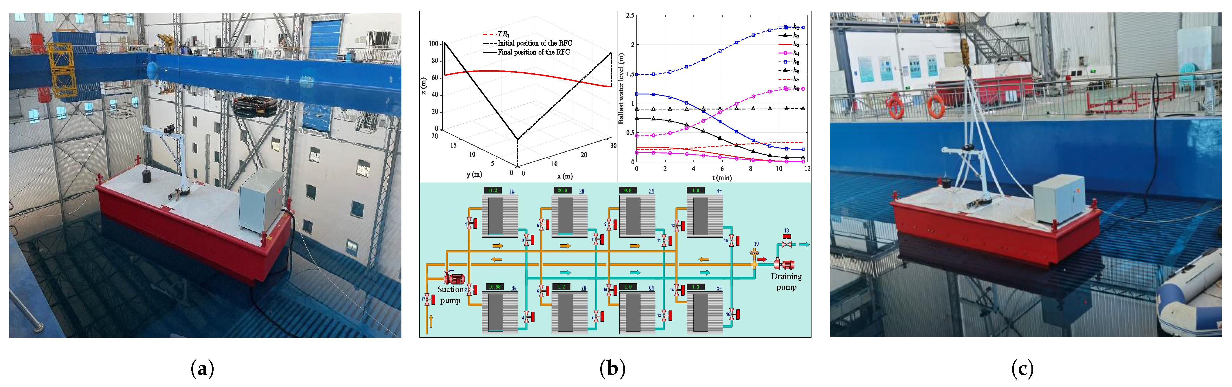
Section 6 presents the verification experiments, validating the feasibility of the proposed method in practical operations. Finally, the concluding remarks are given in Section 7.

2. PTP-Based Optimization Method of Ballast Water Allocation

2.1. PTP Theory

The PTP method, designed based on high-degree polynomials, aims to solve complex optimal control problems [19]. From a mathematical perspective, the PTP method tries to find reasonable polynomials corresponding to the position, velocity, and acceleration of the optimal controls for a complex electromechanical system, namely
s = s ( t ) s ˙ = s ˙ ( t ) s ¨ = s ¨ ( t ) t [ t i , t f ] ,
In the PTP method, s ( t ) , s ˙ ( t ) , and s ¨ ( t ) can all be further derived as nth-degree polynomials:
s ( t ) = b 0 + b 1 t + b 2 t 2 + b 3 t 3 + + b n t n s ˙ ( t ) = b 1 + 2 b 2 t + 3 b 3 t 2 + 4 b 4 t 3 + + n b n t n 1 , s ¨ ( t ) = 2 b 2 + 6 b 3 t + 12 b 4 t 2 + 20 b 5 t 3 + + n ( n 1 ) b n t n 2
Typically, the system starts from a stationary state and comes to a stop at a specific final position. The final position of the components in a mechanical system is typically determined by the tasks performed, and usually it deviates from the initial position. The startup and shutdown processes of the system should be both gradual changes for ensuring the stability and safety of the system operations. Therefore, the following motion constraints are imposed on the system at the initial and final instants:
s ( t i ) = b 0 = 0 s ˙ ( t i ) = b 1 = 0 , s ¨ ( t i ) = b 2 = 0
s ( t f ) = k s ˙ ( t f ) = 0 , s ¨ ( t f ) = 0
By substituting Equations (3) and (4) into Equation (2), polynomial coefficients b 3 , b 4 and b 5 can be obtained as:
b 3 = 10 k T 3 T 3 b 6 3 T 4 b 7 6 T 5 b 8 10 T 6 b 9 b 4 = 15 k T 4 + 3 T 2 b 6 + 8 T 3 b 7 + 15 T 4 b 8 + 24 T 5 b 9 , b 5 = 6 k T 5 3 T b 6 6 T 2 b 7 10 T 3 b 8 15 T 4 b 9
Through the derivation processes mentioned above, it can be understood that the essence of the PTP theory is to transform an optimal control problem of a dynamic system into a nonlinear constraint problem of solving the corresponding coefficients of a high-degree polynomial [20]. Once the coefficients are determined, the position, velocity, and acceleration of the dynamic system at any time instant can be obtained.

2.2. The PTP-Based Optimization Method for Ballast Water Allocation

In order to meet the requirements of the intelligent operations of the RFC, a PTP-based optimization method of ballast water allocation is proposed in this section, and the corresponding principle framework is illustrated in Figure 2. In conventional process of handling the optimal control problems, the PTP theory is adopted to represent histories of the displacement, the speed, the acceleration, and the jerk. Differently, for the PTP-based optimization method of ballast water allocation proposed in this study, the PTP theory is utilized to describe the ballast water situations of each tank, including the water levels, the rates of water level change, etc. Based on above mode, the optimization processes introduced the PTP theory are explained as follows, as illustrated in Figure 2.
(i)
By considering the given information of the lifting task, including the lifting trajectory, the lifting load, the lifting speed, etc., the ballast water allocation model of the RFC is established, and the water level changes of each ballast tank are described using the PTP theory. In this way, the optimal control problem of the ballast water allocation is transfered to a nonlinear constraint problem and the polynomial coefficients are treated as design variables;
(ii)
Time discretization is performed within the entire time domain of the RFC’s lifting processes. For all the time instants obtained from the discretization, one-to-one correspondences between the lifting trajectory positions and the water levels in each ballast tank are established based on the principle of torque balance. This step effectively connects the lifting trajectory with the water-level variation in each tank, laying the foundation for subsequent optimization processes;
(iii)
The optimization model of the PTP-based optimization method of ballast water allocation is built by considering relevant system constraints while the RFC is working, such as vessel tilt angles and the moment equilibrium;
(iv)
An appropriate intelligent optimization algorithm is selected to solve the PTP-based optimization problem. The convergence condition of the optimization process is set as the residual error being less than the residual error standard. If the converge condition is met, the optimal ballast water-allocation scheme is obtained; otherwise, the optimizer will update the design variables and continue with the iterative optimizing process.
It should be noted that the “residual error” mentioned here is identical to the traditional definition of residual error in the optimization field. The “residual error” in optimization process is the difference between the measured values and those predicted by the optimization algorithm during iterations. In other words, it represents the extent to which the optimization process has successfully minimized the objective function or achieved convergence. The “residual error standard” refers to a predefined criterion or threshold used during the optimization iteration process, which assesses convergence and guides the algorithm to achieve the desired accuracy or minimize the objective function within limits.

3. Ballast Water-Allocation Optimization Problem Formulation

3.1. Objective Function

For the ballast system of the RFC, the total water quantity for allocation is the most critical indicator that reflects the efficiency and energy-saving aspects of the ballast plan. A relatively small amount of ballast water allocation means that the ballast operation can be completed in a shorter time, thus increasing the efficiency of the lifting operation. In addition, a smaller amount of ballast water allocation can reduce the energy consumption of ballast pumps and other executive devices, reduce the number of tanks involved in the ballast operation, and effectively reduce the losses of various hardware. Therefore, the total quantity of the ballast water allocation of the RFC serves as the objective function in this study, namely
f = 1 2 p = 1 q | Δ h p f | S p ρ w ,

3.2. Design Variables

As mentioned in Section 2, the proposed optimization method of ballast water allocation in this study is based on the PTP theory, which transforms the optimal control problem of ballast water allocation into a nonlinear constrained problem of solving the corresponding high-degree polynomial coefficients. Thus, the polynomial coefficients involved in the PTP theory should be taken as the design variables. The degree of a polynomial determines the degree of freedom of the polynomial curve, which in turn determines the reliability and accuracy of the optimization results. Additionally, as seen from the principle of the proposed PTP-based optimization method, the degree of the polynomial directly influences the number of design variables, namely influencing the solving efficiency of the optimization problem. Comprehensively, a high degree of the polynomial will increase the accuracy of the optimization solution but decrease the solving speed, while a low degree of the polynomial will increase the solving speed but decrease the solving accuracy. Based on a relevant study performed in Ref. [21], a sixth-degree polynomial can better balance the solving accuracy and speed for the PTP method. Therefore, in this study, a sixth-degree polynomial is selected to describe the water levels in each ballast tank, namely
h p ( t ) = b p 0 + b p 1 t + b p 2 t 2 + b p 3 t 3 + b p 4 t 4 + b p 5 t 5 + b p 6 t 6 ,
From a dynamic perspective, the speed and acceleration of the water level change in any ballast tank at both the initial and final instants should be zero, so as to realize smooth lifting operations. Thus, the following derivations can be obtained:
h p ( 0 ) = h p 0 h ˙ p ( 0 ) = 0 , h ¨ p ( 0 ) = 0
h p ( t f ) = h p f h ˙ p ( t f ) = 0 , h ¨ p ( t f ) = 0
Consequently, the polynomial coefficients for the ballast water level can be written as the following:
b p 0 = 0 b p 1 = 0 b p 2 = 0 b p 3 = 10 ( h p f h p 0 ) t f 3 t f 3 b p 6 b p 4 = 15 ( h p f h p 0 ) t f 4 + 3 t f 2 b p 6 b p 5 = 6 ( h p f h p 0 ) t f 5 3 t f 3 b p 6
As seen from Equation (10), the corresponding design variables of the PTP-based optimization method for RFC ballast water allocation can be determined as the following:
x B = [ b p 6 , h p f ] ( p = 1 , 2 , 3 , , q ) ,
Based on the PTP theory, the range of values for the polynomial coefficient b p 6 should be set from negative infinity to positive infinity. Structurally, during the ballast water-allocation process, the water level in each ballast tank should not exceed the height of the tank ( h p T , m). From the engineering practice, it is not advisable to simply let the system run at full capacity for the sake of improving the operation efficiency. Such an operation on the one hand may impose an excessive burden on the hardware and add unnecessary costs, and on the other hand it may cause a speed mismatch between the crane and the ballast system. In conclusion, the upper and lower boundaries of the design variables in the ballast water reallocation optimization are listed in Table 1.

3.3. Constraints

Constraints are crucial for ensuring that the optimization model conforms to the engineering reality and safety requirements. Therefore, the analysis and determination of the constraints used in the PTP-based optimization are key to ensuring the feasibility and effectiveness of the obtained scheme of the actual ballast water-allocating operations.
(i)
Hull inclination constraints
Ensuring the safety and stability of the vessel is the basic requirement of all the offshore lifting operations, so the heel and trim angles of the hull are two key indicators of the operational safety of the RFC. According to Ref. [22], the heeling angle θ (°, deg) should be kept within [−5°, +5°] and the trim angle ϕ (°, deg) should be maintained within [−2°, +2°] during the lifting operations, namely
5 θ + 5 ,
2 ϕ + 2
The detailed expressions of the heeling angle θ and trim angle ϕ are as follows:
θ = arctan { [ m d y + m 2 y 2 g + Q 0 y b + M Ey ] / [ ( Δ + m ) G 1 M 1 ¯ ] }
ϕ = arctan { [ m d x + m 2 x 2 g + Q 0 x b + M Ex ] / [ ( Δ + m ) G 1 M 1 L ¯ ] }
From Equations (14) and (15), it is seen that the hull inclination is caused by the overturning moments generated by the load and the boom, the ballast moments generated by the ballast water allocation, the environmental moments generated by sea state changes, and the righting moments generated by the buoyancy. To better describe the ballast moments of each ballast tank, the ballast tank is treated as a regular cuboid structure in this study, so the transverse and longitudinal positions of the barycenter of the ballast water in each ballast tank can be obtained using the following:
y b = p = 1 q ρ w h p S p y p Q 0 ,
x b = p = 1 q ρ w h p S p x p Q 0 ,
The environmental moments caused by sea conditions mainly include wind moments and wave moments. Currently, almost all the RFCs are equipped with the Dynamic Positioning System (DPS) to counteract external forces. The DPS relies on Motion Reference Units (MRUs) to obtain external forces causing the hull inclination, utilizes the control system to obtain the thrust distribution scheme, and thereby drives the thrusters to counteract the external forces [23,24]. Therefore, the inclination changes caused by external forces do not have significant effects on the ballast process of an RFC equipped with a DPS. However, for demonstrating the superiority of the proposed PTP-based optimization method of ballast water allocation, the wind and wave moments in actual sea states are still taken into account in this study. In this study, relevant wave parameters, including the wave height, wave velocity, wave length, etc., are assumed to remain constant during offshore operations. The wave-induced force and moment on the hull are assumed to adhere to the Froude–Krylov hypothesis. Thus, the corresponding expressions of the wind and wave moments can be derived as follows [25,26,27]:
M Ex = M windx + M wavex = 1 2 ρ a A c L V 2 C wx + 1 2 ρ w L 2 a 2 sin χ C mx
M Ey = M windy + M wavey = 1 2 ρ a A c L V 2 C wy + 1 2 ρ w L 2 a 2 sin χ C my
Not all the ballast tanks are full while performing the lifting operations, so the free surface effect can not be ignored while deriving the righting moment of the hull. The transverse and longitudinal metacentric heights are directly influenced by the free surface effect. Based on the hull structures, the transverse metacentric height ( G 1 M 1 ¯ , m) and the longitudinal metacentric height ( G 1 M 1 L ¯ , m) can be derived as follows [28,29]:
G 1 M 1 ¯ = G M ¯ + m Δ + m [ ( T + Δ T 2 ) z G M ¯ ] p = 1 q ρ w I x p Δ ,
G 1 M 1 L ¯ = G M L ¯ + m Δ + m [ ( T + Δ T 2 ) z G M L ¯ ] p = 1 q ρ w I y p Δ ,
(ii)
Ballast water level constraint
During the ballast water allocation process, the water level of each ballast tank ( h p , m) should not exceed the structural depth of the corresponding ballast tank itself ( h p T , m), namely
0 h p h p T
(iii)
Constraint of the ballast water allocation rate
During the lifting operation, the ballast water allocations between different tanks are driven by the ballast pump, so the totally instantaneous allocation rate of the ballast system ( Q total , t) can not exceed the maximum pumping rate achieved by the ballast pump ( Q max , t), namely
Q total Q max
(iv)
Total ballast water constraint
To prevent biological contamination, the internal allocation (the ballast system does not conduct ballast water exchange operations with the sea, and the total amount of ballast water is unchanged) is adopted in this study for ballasting. Therefore, throughout the entire ballasting process, the total amount of ballast water loaded in the tanks should remain constant and equal to the initial ballast water quantity, ( Q 0 , t), as expressed by the following:
Q ( t ) = p = 1 q ρ w g S p h p = Q 0
Summarily, the inequality constraints g B and equality constraints h B in the optimization model of the PTP-based optimization method for ballast water allocation are the following:
g B = g B 1 g B 2 g B 3 g B 4 g B 5 g B 6 = θ 5 5 θ ϕ 2 2 ϕ h p h p T Q total Q max 0
h B = h B 1 h B 2 h B 3 = θ 0 ϕ 0 Q Q 0 = 0

3.4. Optimization Model

As analyzed above, the final optimization model of the PTP-based optimization method of ballast water allocation for the RFC can be cast as the following:
find x B = [ b p 6 , h p f ] min f B = 1 2 p = 1 q | Δ h p f | S p ρ w s . t . g B = [ g B 1 , g B 2 , g B 3 , g B 4 , g B 5 , g B 6 ] T 0 h B = [ h B 1 , h B 2 , h B 3 ] T = 0

4. Case Study and Superiority Verification

4.1. Case Study of the PTP-Based Method

In this section, the feasibility of the proposed PTP-based optimization method for ballast water allocation is evaluated using a case study. The “Nan Tian Long” RFC currently serving in China is selected as the object of study and the corresponding structure and performance parameters are listed in Table 2 [1]. To facilitate the calculation, the actual “Nan Tian Lon” RFC is simplified into two main components, including the upper lifting system and the internal ballast system, as illustrated in 
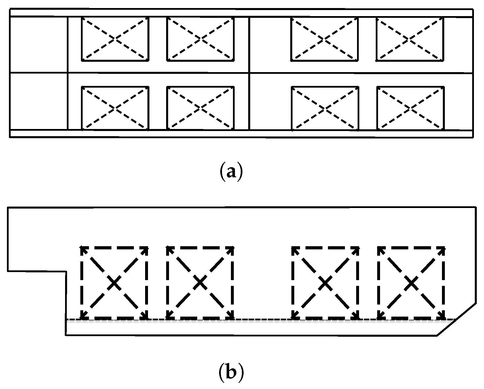
Figure 3. As observed, the crane includes a rotating base for executing rotational activities, an amplitude boom for controlling the span size, and hoisting ropes for lifting operations. For the ballast system, all the ballast tanks inside the hull are simplified into eight symmetrical rectangular structures, and the corresponding arrangements and sizes of the simplified tanks are illustrated in detail in Figure 4, in which 1∼8 denote the tank number. Complementarily, the structure parameters of the simplified tanks are also stated in 
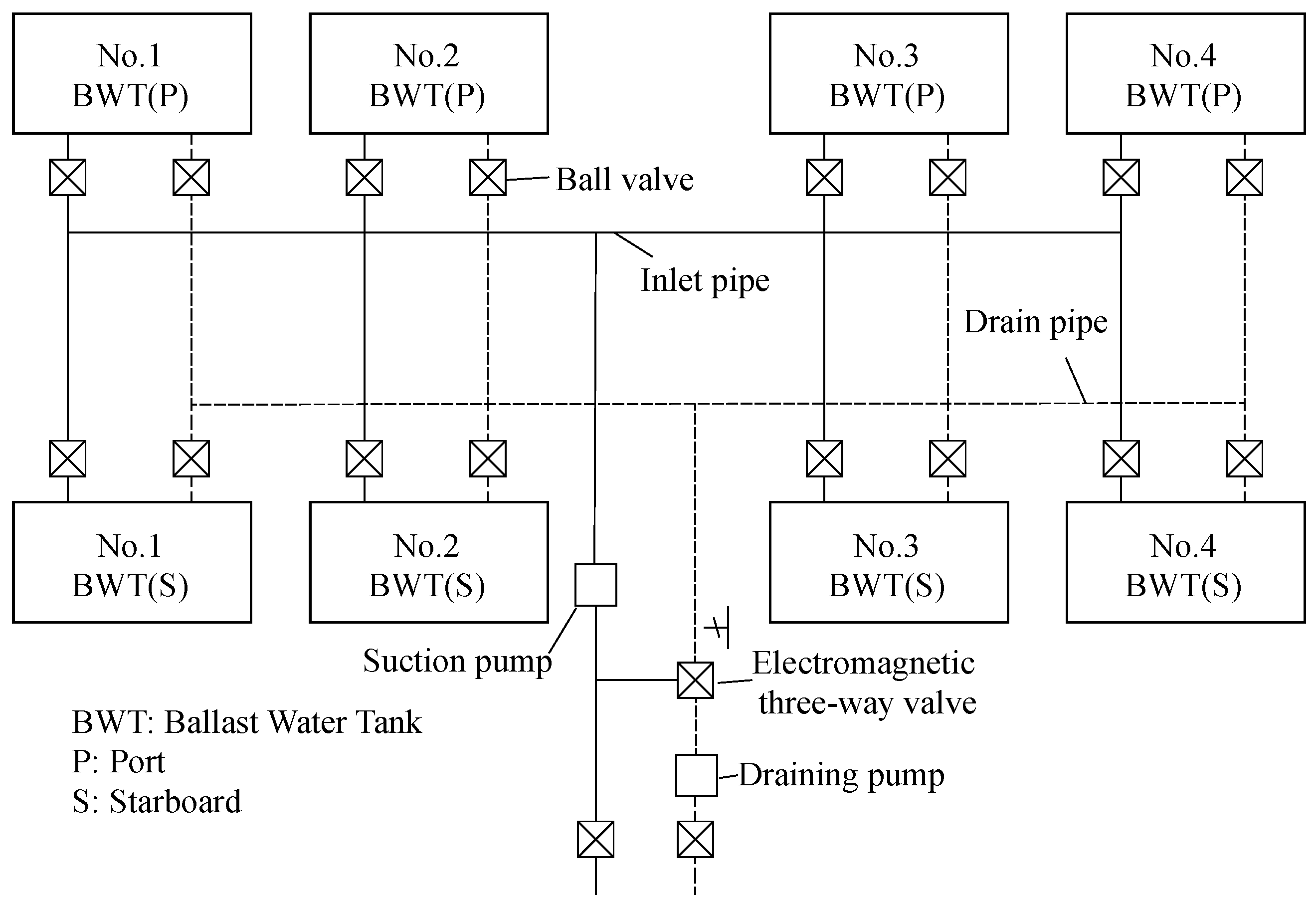
Table 2. For better clarification, a schematic diagram of the corresponding ballast piping system is illustrated in Figure 5, from which it can be seen that any ballast tank can freely exchange ballast water with the other seven tanks. In addition, to facilitate the description of the optimization problem of the ballast water allocation, a Cartesian coordinate system is established, as shown in Figure 3, with the z-axis along the vertical line passing through the barycenter of the RFC and the x-axis along the bottom surface of the RFC in the direction of the stern.
In this case study, the lifting task is set to lift a 300 t load from a 0° position at the stern and rotate horizontally to a 90° position with the lifting radius being 30 m. In detail, the initial and ending positions of the lifting trajectory predefined here are (65, 0, 70) and (35, 30, 70), respectively. Consequently, there is no direct contact between the load and the deck throughout the entire lifting process in this case study. The time consumption of the ballast water allocation process is the same as the lifting duration, which is 12.00 min. The corresponding sea conditions are listed in Table 3.
In this section, the genetic algorithm is selected to align with theoptimization model of the ballast water allocation. The corresponding population size, the number of iterations, the crossover rate, and the mutation rate are set to 100, 50, 0.8, and 0.01, respectively. The computer configuration used is the Windows 10 operating system, equipped with a 2.60 GHz Intel(R) Core(TM) i7-10750H processor (Intel, Santa Clara, CA, USA) and 8.0 GB of memory, located in Dalian Maritime University, Dalian, China.
The optimal value of the objective function obtained from the PTP-based optimization method is 489.54 t, and the corresponding optimal design variables are listed in Table 4. 
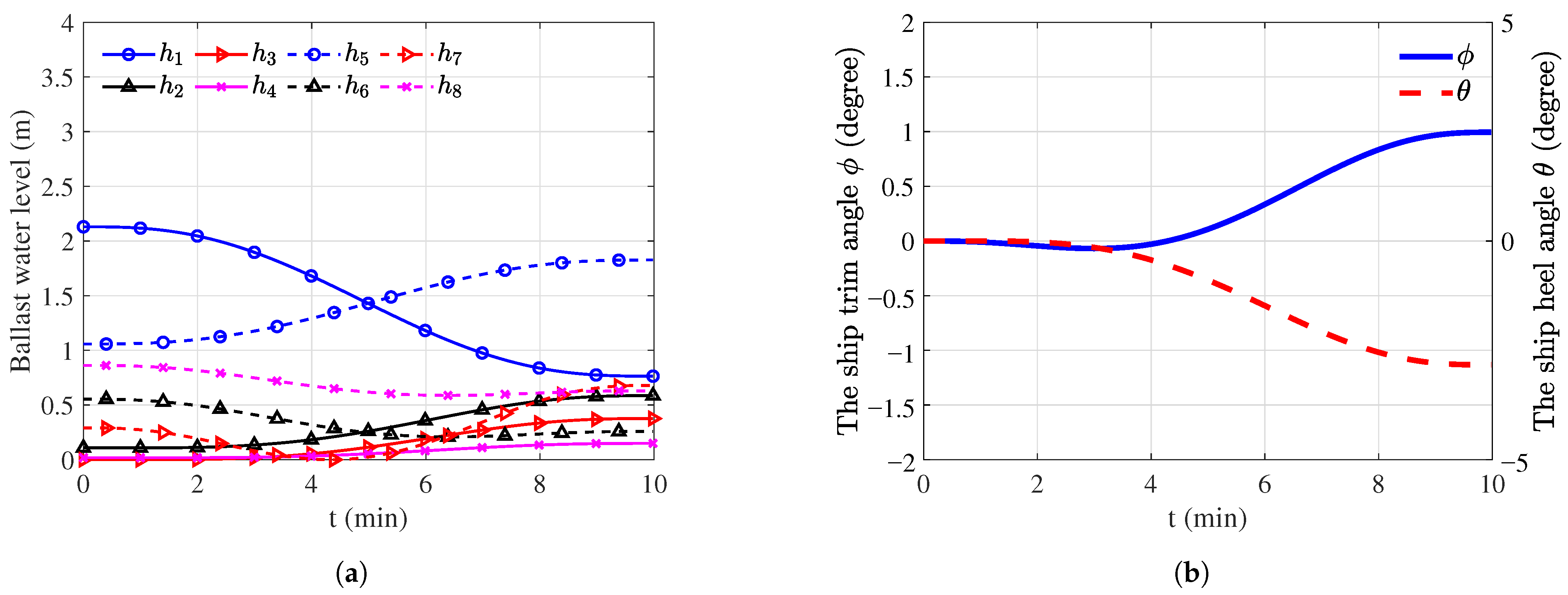
Figure 6a shows the optimal ballast water-level curve obtained from the proposed PTP-based optimization method. Overall, four ballast tanks (Tanks 1, 4, 5, and 8) are involved in the ballasting process, which is achieved using the optimization methods, rather than being attributed to limitations in the physical structure of the ballast system itself. As seen, the water level curves of Tanks 1, 4, 5, and 8 exhibit smooth and continuous characteristics. As the crane rotates, the water levels in Tanks 1 and 4, which are on the same side as the cargo lifting, gradually decrease until they are completely emptied. In contrast, the water levels in Tanks 5 and 8, located on the opposite side of the cargo-lifting direction, show gradual rising trends. Furthermore, it is found that the amplitude of the water level changes in Tanks 1 and 4, located farther from the cargo-lifting position, is significantly larger than that in Tanks 5 and 8, located at the stern.
The duration curves of the heeling and trim angles of the hull during the lifting operation are illustrated in Figure 6b, in which the left ordinate indicates the trim inclination and the right ordinate indicates the heeling inclination. It is evident that the maximum heeling angle and trim angle of the hull are both within the safe range (the safe range of heeling angles is −5°∼+5°, and the safe range of trim angles is −2°∼+2°), meeting the industry requirements of the RFC operations.
In summary, the PTP-based optimization method proposed in this study can successfully devise an optimal ballast water allocation scheme for RFCs. The obtained ballasting process is smooth, continuous, and complies with the safety requirements of the relevant industry, fully demonstrating the feasibility of the PTP-based optimization method in solving such problems.

4.2. Comparison Analysis of the PTP-Based Method

4.2.1. Conventional Optimization Method for Ballast Water Allocation

For the ballast water allocation problem of RFCs, the current mainstream optimization strategy is the Multi-stage Optimization method based on the Dynamic Programming Theory (DPT-MO), which is also widely used in mathematics, computer science, and operations research, etc. The specific flow of using the DPT-MO method to solve the optimization problem of ballast water allocation is presented in Figure 7. As seen, the dynamic allocation process of the ballast water during the lifting operation is uniformly discretized into multiple stages (for example discretized according to the rotation angle of the boom). For each stage, an optimization solution process is carried out independently to obtain several feasible allocation schemes; then, the optimal solution at each stage which can achieve the overall optimal allocation scheme is retained one by one based on the recursion relation, and other solutions are discarded. Finally, all the optimal local solutions are connected to obtain an overall optimal strategy.
Specifically, the DPT-MO method essentially transforms the ballast water allocation problem into a series of sub-optimization problems. This approach requires multiple iterations and solutions throughout the entire optimization process, which inevitably leads to a lower computational efficiency. As a result, a significant amount of computational resources and time are consumed, and it may even cause the curse of dimensionality during numerical solving.

4.2.2. Comparison Results Analysis

In order to verify the feasibility and superiority of the proposed method, it is compared with the conventional method. To ensure the reliability of the comparison, the two optimization methods need to solve the same engineering problems, including consistent lifting tasks, operating conditions, etc.
After setting the same constraints and objective function as the PTP-based optimization model, the duration curves of the ballast water level obtained from the DPT-MO method are shown in Figure 8. The water level variations of each corresponding tank obtained from the DPT-MO method and the PTP method are similar, but there are still noticeable differences. From Figure 8, it is observed that the water level curve obtained from the DPT-MO method is not smooth and exhibits local abrupt changes, which may have negative impacts on the stability of the RFC operation. In contrast, the water level curve obtained from the PTP-based method is smoother, better meeting the stability requirements of offshore lifting operations, and facilitating the controls of the ballast system. Additionally, it is evident from Figure 8 that the water level variation in ballast Tank 4 obtained from the PTP-based method is much smaller compared to the DPT-MO method. This indicates that the PTP-based method can effectively decrease the amount of ballast water allocation, reduce time costs, and lower the energy consumption of the system.
The detailed comparisons of the obtained allocation schemes between the DPT-MO method and the PTP method are presented in Table 5. It is observed that the PTP-based method leads to a significant reduction in the quantity of the ballast water allocation, decreasing from 595.22 t to 489.54 t by 17.75% compared to the DPT-MO method. Due to the reduction in the total amount of ballast water allocation, the time cost of the ballast scheme obtained from the PTP-based method is lower. In terms of decision-making time, the DPT-MO method takes 6.30 min to complete the optimization, while the PTP-based method requires around 1.67 min, which is nearly 1/4 of DPT-MO method. The significant decrease in decision-making time is mainly attributed to the different solution strategies employed by these two methods. The DPT-MO method essentially divides the ballast water allocation process into multiple decision stages and performs optimization solving at each stage. In contrast, the PTP-based method is a complete and continuous solving process, and it performs a single solution for the entire ballasting process. In addition, the heeling and trim angles of the hull corresponding to the DPT-MO method and the PTP-based method are both kept within the safety range specified by the industry (≤2°).

4.3. Superiority Discussion

In summary, the PTP-based optimization method proposed in this paper can successfully design the optimal ballast water allocation plan for the RFC. The water level curve changes smoothly, and the process is continuous. Compared to traditional methods, it can better adapt to the matching of electronic control parameters and is more conducive to achieving the reliable control of ballast water allocation in practical operations. Additionally, the inclination angles of the hull obtained through the PTP-based optimization method meet the safety requirements of the relevant industry, ensuring the safety and stability of the entire offshore lifting operation. In addition, it can be concluded that under the same working conditions, the PTP-based method proposed in this study can significantly improve the comprehensive working performance of the ballast system, especially in the aspects of ballast water allocation efficiency, ballast water allocation quantity, and decision-making time. Through comparison with traditional methods, it is evident that the PTP-based optimization method effectively addresses the RFC ballast water allocation problem, demonstrating certain feasibility and superiority.

5. Numerical Experiments for the PTP-Based Optimization Method

Although actual offshore lifting operation scenarios are diverse and complex, all lifting tasks are fundamentally the combinations of different lifting trajectories and load masses. Therefore, numerical experiments for different lifting trajectories and load masses are conducted in this section to comprehensively evaluate the reliability of the proposed PTP-based optimization method. In practical engineering, the initial water levels in different tanks may vary based on specific working conditions, leading to a slight hull tilt within the safe range of [−5°, +5°]. To facilitate comparison and summarization, this study sets both the initial heel and trim of the hull to zero during the PTP-based optimization of the ballast water allocation problem.

5.1. Numerical Experiments Regarding Different Lifting Trajectories

The lifting trajectory depends on the requirements of the actual lifting task. By analyzing the positional relationship between the starting point and the ending point of the trajectory, there are three basic forms of trajectories: (i) horizontal lifting, (ii) lifting from a higher position to a lower position, and (iii) lifting from a lower position to a higher position. To facilitate comparative analysis and simulate various basic lifting scenarios comprehensively, the lifting starting point is fixed, and the other three ending positions with different heights relative to the lifting starting point (higher than the lifting starting point, the same height as the lifting starting point, and lower than the lifting starting point) are selected, thus forming three basic lifting trajectory types as mentioned. It should be additionally elaborated that the rotation angles of these three lifting activities are all uniformly determined to be 90° in this section. When the load is at the 90° lifting position relative to the hull length, the hull reaches its transverse inclination limit, resulting in the worst safety and stability. If the PTP-based optimization method can formulate a safe and stable ballast water allocation scheme when the load is at the 90° lifting position, then reliable lifting schemes can be developed for any other target positions by the PTP-based method. The starting and ending positions, along with the lifting durations, of the three different lifting-task Trajectories TR1, TR2, and TR3, are listed in Table 6, and the corresponding three-dimensional representations of the trajectories are illustrated in Figure 9. In addition, in this numerical experiment, the lifting loads are uniformly set to be 300 t.
Regarding lifting Trajectory TR1, the optimal ballast scheme is shown in Figure 10, including the duration curves of the water level and the hull inclination. It can be seen in Figure 10a that, as the lifting operation continues, the water level in Tank 2 on the port side shows a downward trend approximately, while the water level in Tank 7 on the starboard side shows rising and then decreasing trends. The water level in Tank 3 decreases slightly, and the corresponding magnitudes of change are minimal. As seen, the actual ballast operation regarding TR1 is mainly determined by three tanks, including Tanks 1, 2, and 7. In addition, it is observed from Figure 10b that the hull inclinations are completely within the safe range.
The optimal ballast water allocation schemes obtained using the PTP-based method for Trajectories TR2 and TR3 are presented in Figure 11 and Figure 12, respectively. From Figure 11a and Figure 12a, the obtained duration curves of the water levels in each ballast tank are continuous and smooth without abrupt changes, which conforms to the practical ballasting controls. From Figure 11b and Figure 12b, both the heeling and trim angles of the hull remain within the safe range throughout the lifting process, fully complying with the safety regulations.
Furthermore, Table 7 compares the optimal lifting schemes obtained by the PTP-based method for the three different lifting trajectories. As seen, the quantity of the ballast water allocation decreases with the vertical height of the trajectory ending point increasing; similarly, the energy consumption of the ballasting operations also decreases with the vertical height of the trajectory ending point increasing. From the above comparison, it can be seen that the proposed PTP-based optimization method can effectively obtain the optimal ballast water allocation schemes for various lifting trajectories, and all the schemes meet the safety requirements of the offshore lifting industry.

5.2. Numerical Experiments Regarding Different Lifting Loads

In practical offshore lifting processes, different lifting tasks correspond to different load masses, which will inevitably affect the formulation of ballast water allocation schemes. Therefore, it is essential to conduct a performance verification of the proposed PTP-based optimization method with respect to different lifting load masses. Under the premise of not exceeding the lifting capacity of the RFC, numerical experiments are conducted with lifting loads of 200 t, 300 t, and 400 t, respectively. The corresponding lifting trajectory is uniformly set as Trajectory TR2, as listed in Table 6, so as to facilitate the analysis of the impact of load mass on the optimization results.
For the 200 t load mass, the duration curves of the water levels in each tank are shown in Figure 13a. As the load rotates towards the port side, the water level in Tank 3 on the port side drops significantly, while the water level in Tank 7 on the starboard side shows rising trends. However, the water level changes in other tanks are relatively small. From Figure 13b, it is evident that the maximum heeling and trim angles of the hull are both lower than the maximum values required to ensure the safety of the hull. Therefore, when lifting a 200 t heavy object, the PTP-based optimization method proposed in this paper can successfully plan a safe and stable ballast water allocation scheme.
For the 300 t loading mass, the water level variations and hull inclination changes have been discussed in detail in Section 5.1, and the corresponding optimal ballasting scheme is illustrated in Figure 11. The optimal ballast scheme regarding the 400 t lifting load obtained using the PTP-based method is illustrated in Figure 14. From Figure 14, it is obvious that the water levels in Tanks 1 and 5 drop in varying degrees, while the water levels in Tanks 2 and 6 show rising trends. The water level changes in other tanks are relatively small. Additionally, the hull inclinations are maintained within the safe range for lifting operations. As seen, the proposed PTP-based method can still output the optimal ballast water allocation scheme even when the lifting load increases to 400 t.
Comparisons between the ballast water allocation schemes regarding different lifting loads using the PTP-based optimization method are presented in Table 8. It is seen that the lifting load has a significant influence on the maximum heeling angle, namely the maximum heeling angle increasing with the load mass increasing. In addition, both the quantity of the ballast water allocation and the energy consumption of the ballasting operations present upward trends with the lifting load mass increasing. As analyzed above, it can be concluded that the PTP-based method proposed in this paper can effectively complete the formulation of safe and stable ballast water allocation schemes when dealing with different lifting loads.

5.3. Resulting Discussion of Numerical Experiments

The actual scenarios of offshore lifting operations are diverse and complex, but all lifting tasks are essentially combinations of different lifting trajectories and load masses. In this section, to faithfully replicate as many operating tasks as possible, various numerical experiments are conducted with different lifting trajectories and load masses. From the numerical experiment results, it is evident that the proposed PTP-based ballast water allocation optimization method remains efficient and reliable in finding corresponding ballast water allocation solutions for diverse lifting tasks. All solutions meet the safety requirements of the offshore lifting industry. Furthermore, the optimal water level curves of the ballast tanks obtained from the PTP-based optimization method exhibit smooth and continuous changes, which are more conducive for reliable control of ballast allocation by facilitating the electronic controls in practical operations. In summary, the PTP-based method proposed in this paper can effectively and reliably formulate safe and stable ballast water allocation plans for various offshore lifting tasks of RFCs.

6. Experimental Validation of the PTP-Based Optimization of the Ballast Water Allocation

The reliability and feasibility of a theoretical method need to be verified not only by numerical experiments under multiple conditions, but also by operational experiments on real physical systems. In this section, the RFC physical test stand is built, and the real operation of experimental research is carried out to verified the reliability and feasibility of the PTP-based optimization method proposed in this study.

6.1. RFC Physical Test Stand Establishment

In order to facilitate the experimental verification research, a new RFC physical test stand has been developed in this study. The schematic diagram of the RFC physical test stand is presented in Figure 15, in which the corresponding key structures and components are noted in detail, including the electrical control box, the winch, the crane jib, the ballast pipe system, the ballast pump, the ballast tanks, and the electronic control valve, etc. The main parameters of this platform are listed in Table 9, and the corresponding main structure dimension is 4.5 m (length overall) × 1.5 m (molded breadth) × 0.7 m (molded depth). The configuration of the ballast system is particularly critical to determine the quality of the physical experiment of the ballast water allocation. In order to facilitate the numerical analysis and system control, the ballast tanks of the RFC test stand are arranged symmetrically, as shown in Figure 16, in which all ballast tanks are connected in pairs through pipelines. The ballast system of the test stand relies on the intake pump and the drainage pump to complete the water supply and drainage operations, as illustrated in the piping diagram of Figure 17. Each ballast tank is equipped with solenoid valves in the inlet and outlet pipes, respectively, to control the water supply and drainage actions, as illustrated in Figure 15.
The real physical structure of the RFC test stand is presented in Figure 18. In order to realize the real-time data acquisition from the ballasting experiments of the RFC test stand, relevant sensors are installed at key positions, as illustrated in Figure 18. A hull inclination sensor (two-axis obliquity sensor) is installed on the centerline of the hull to obtain real-time inclination data. An angle sensor is installed on the crane to measure the elevation angle of the jib. A rotary encoder installed on the slewing base of the crane is used to measure the column slewing angle in real time. Each ballast tank is equipped with a liquid level sensor for the real-time acquisition of the water level data of the corresponding tank. Additionally, the test stand is equipped with a complete electrical control system, which can collect real-time data from various sensors and display relevant results on the user interface. Crucially, the electrical control system can also automatically execute lifting operations according to manually input ballast and lifting control parameters obtained from the theoretical calculation.

6.2. Experimental Scheme and Procedure

To verify the reliability and feasibility of the proposed PTP-based optimization method of ballast water allocation, it is necessary to use the real physical test stand to implement the ballast water allocation scheme obtained using the PTP-based method. During the lifting experiment, the hull heeling and trim angles should be measured in real time. If the hull inclination meets the safety operation standard, the reliability and feasibility of the proposed PTP-based method can be proved, as well as its applicability in actual offshore lifting operations.
The whole experimental process is carried out in a large experimental pool, the size of which is 50 m (length) × 30 m (width) × 5 m (depth), and the depths of some local areas are up to 10 m. According to the structural characteristics of the test stand, on the premise of ensuring safety and reliability, the lifting experiment is carried out in accordance with the following steps:
(i)
The RFC test stand is slowly launched in the designated water area by the overhead crane and its position angle is adjusted for experimental observation, as illustrated in Figure 19a. After that, the test stand needs to stand for 10 min in order to eliminate the influence of ripples on the accuracy of the subsequent test data;
(ii)
According to the per-set lifting trajectory and load weight, the optimal ballast water allocation scheme is obtained by performing the PTP-based method, and the corresponding logical instructions of the operations of the test stand are written, as shown in Figure 19b;
(iii)
Based on the written logic instructions, the test stand is controlled to perform the lifting operations according to the pre-set lifting trajectory and the optimal ballast water allocation scheme obtained using the PTP-based method, as illustrated in Figure 19c. During the test process, the key experimental data, including the heeling angle, the trim angle, and the time consumption are collected and recorded in real time for subsequent analysis;
(iv)
The data of the heeling and trim angles of the hull are processed and compared with the theoretical values to evaluate the reliability of the ballast water allocation scheme obtained from the PTP-based method. Additionally, the heeling and trim angles are also assessed to determine whether they meet the safety requirements for offshore lifting operations. If the requirements are met, the feasibility of the PTP-based method in practical applications can be confirmed.
Figure 19. Processes of the lifting experiment: (a) launching the RFC test stand, (b) obtaining the allocation scheme and corresponding logical instructions, and (c) performing the lifting operations.
Jmse 12 00437 g019

6.3. Resulting Discussions of Physical Experiments

For the experiment, the per-set lifting trajectory is set to be Trajectory TR1 as mentioned in Section 5, and the lifting load is determined to be 25 kg. In order to reduce the experimental error and improve the corresponding reliability, the same experiment is repeated five times for the above load and trajectory. By collecting and processing the real-time data of the lifting experiments, comparisons of the hull inclination between the theoretical and experimental values are illustrated in Figure 20. The dotted lines with markers represent the histories of the heeling and trim angles obtained from the five repeated lifting experiments. The dotted lines without markers represent the average values of the heeling and trim angles obtained by the five repeated experiments. The theoretical values of the heeling and trim angles obtained from the PTP-based optimization method of ballast water allocation are represented by solid lines.
From Figure 20, it is observed that the variation trends in the heeling and trim angles obtained by the actual experiments are very close to the correspondingly theoretical curves obtained by the PTP-based method. This strongly proves that the proposed PTP-based method can provide an effective solution for practical applications of the ballast water allocation for offshore lifting activities. Specifically, the variation range of theoretical trim angles obtained using the PTP-based method is −0.79°∼+0.27°, and the variation range of theoretical heeling angles is −0.79°∼+0.92°. The variation range of trim angles obtained by the actual experiment is −0.99°∼+0.13°, and the variation range of actual heeling angles is −1.32°∼+0.95°. By comparison, it is seen that there is a certain deviation between the theoretical value and the experimental value. Through in-depth analysis, this deviation may be caused by, on the one hand, the inaccurate monitoring of experimental data due to sensor errors, and on the other hand, the delay in the valve switch and water flow in the pipeline. In general, such kinds of deviation between the theoretical and experimental values is common in practice, and the corresponding deviation regarding this experiment is within the acceptable range, which will not affect the rationality and validity of the experimental results. In addition, the variation ranges of heeling angles and trim angles measured in this actual experiment fully meet the safety requirements of offshore lifting operations.
Through the above physical experiment processes and results, it can be demonstrated that the ballast water allocation control curves obtained from the PTP-based optimization method proposed in this study can smoothly and successfully drive the physical RFC to perform lifting operations, ensuring stable and reliable operation processes. The real-time inclination angle data obtained during the actual lifting operations are consistent with the inclination angle obtained from the PTP-based ballast water allocation optimization method, and they remain within the safety range specified by the industry regulations. This can effectively prove that the PTP-based optimization method can ensure the safety of actual offshore lifting operations. Therefore, the PTP-based ballast water allocation optimization method proposed in this paper demonstrates a certain degree of feasibility and reliability in practical applications.

7. Conclusions and Future Work

The current ballast water allocation processes of the RFC rely on manual operations, which are susceptible to factors such as personnel status and sea conditions, leading to low lifting efficiency, high energy consumption, and poor safety. The intelligent and automatic allocation of ballast water is an effective way to address the above issues; however, the relevant industry lacks reliable and efficient optimization methods for ballast water allocation. Therefore, this paper proposes an efficient and continuously solvable optimization method for ballast water allocation based on the PTP theory, transforming the traditional optimal control problem into a nonlinear constraint problem. Under the same working conditions, the proposed PTP-based optimization method reduces the energy consumption by 17.75% compared to the conventional method. Additionally, the PTP-based optimization method significantly reduces the decision-making time by 73.49% compared to the conventional method, making it more suitable for the efficiency requirements of the intelligent ballast water allocation. Numerical experiments are conducted to verify the superiority and reliability of the proposed method, and practical water-lifting experiments are also performed to verify the engineering feasibility of the PTP-based ballast water-allocation method. The PTP-based optimization method of ballast water allocation can significantly improve the safety and energy efficiency of RFC operations, laying a theoretical and methodological foundation for the intelligent development of the RFC and other maritime equipment.
The PTP-based optimization method of ballast water allocation proposed in this study is based on the known lifting trajectory of the RFC; namely, the obtained ballast allocation scheme is adapted to the known lifting trajectory. However, in actual working conditions, ballast water allocation and lifting trajectory interact with each other and jointly determine the safety and economy of offshore lifting operations. Therefore, it is necessary to study the collaborative optimization method of ballast water allocation and lifting trajectory in further work. During lifting operations in local waters, the external allocation operating mode of the ballast system (the ballast water may be exchanged between the tanks and the sea) can be utilized. Thus, further research into enhancing the proposed PTP-based optimization method for the external allocation operating mode is a key focus of our future work. In actual operational processes, the pump failure and leakage have significant impacts on the performance of the RFC; therefore, it is crucial to take into account these issues during the optimization process of ballast water allocation. Additionally, future research efforts can explore the inverse design aspect of the barge, specifically concentrating on determining the dimensions and positions of its ballast tanks. This can be achieved by leveraging the proposed PTP-based optimization method for the allocation of ballast water.

Author Contributions

X.W.: Writing—original draft, Methodology, Verification, Resources, Supervision. Y.Y.: Writing—original draft, Methodology, Verification, Experiment, Investigation. S.L.: Verification, Experiment, Investigation. J.Z.: Writing—original draft, Methodology. Z.L.: Supervision, Resources. All authors have read and agreed to the published version of the manuscript.

Funding

This work is supported by National Natural Science Foundation of China (Grant No. 52201406); Doctoral Start-up Foundation of Liaoning Province (Grant No. 2021-BS-074); Dalian Science and Technology Innovation Fund Project (Grant No. 2020JJ25CY016); and Fundamental Research Funds for the Central Universities (Grant No. 3132023117, 3132023516, 017231017, and 3132023606).

Institutional Review Board Statement

Not applicable.

Informed Consent Statement

Not applicable.

Data Availability Statement

Data will be made available on request.

Acknowledgments

We appreciate the reviewers for their valuable comments, which were crucial to shaping this study. At the same time, we are also grateful for the financial support provided by the above-mentioned funds.

Conflicts of Interest

The authors declare that they have no known competing financial interests or personal relationships that could have appeared to influence the work reported in this paper.

Abbreviations

A c (m3)Transverse projected area of the ship above the waterline
a (m)Wave amplitude
b n Polynomial coefficients
b p 0 b p 6 Polynomial coefficients
C mx , C my Wave moment coefficients in x and y directions, respectively
C wx , C wy Wind moment coefficients in x and y directions, respectively
d x (m)Longitudinal positions of the load barycenter
d y (m)Transverse positions of the load barycenter
f B The optimization objective
G M ¯ (m)Initial transverse metacentric height before loading
G M L ¯ (m)Initial longitudinal metacentric height before loading
G 1 M 1 ¯ (m)Transverse metacentric height influenced by free surface effect
G 1 M 1 L ¯ (m)Longitudinal metacentric height influenced by free surface effect
g B The inequality constraints
h B The equality constraints
h p ( t ) (m)Water level change of ballast tank p at time t
h ˙ p (m/s)Speed of water level change in ballast tank p
h ¨ p (m/s2)Acceleration of water level change in ballast tank p
h p 0 (m)Initial water levels in ballast tank p
h p f (m)Final water levels in ballast tank p
I x p (m4)Moment of inertia with respect to the x-axis generated by the
free-surface effect in ballast tank p
I y p (m4)Moment of inertia with respect to the y-axis generated by the
free-surface effect in ballast tank p
kPosition of the system at the final instant
L (m)Overall hull length
M Ex (N·m)Longitudinal environmental moments acting on the hull
M Ey (N·m)Transverse environmental moments acting on the hull
M wavex (N·m)Wave moments on longitudinal directions
M wavey (N·m)Wave moments on transverse directions
M windx (N·m)Wind moments on longitudinal directions
M windy (N·m)Wind moments on transverse directions
m (t)Load mass
m 2 (t)Mass of the crane boom
nNon-negative integer
Q (t)Total amount of ballast water loaded in all the tanks at time t
Q 0 (t)Initial loading capacity of the ballast water
qTotal number of ballast tanks in RFC
S p (m2)Base area of ballast tank p
s ( t ) Position
s ˙ ( t ) Velocity
s ¨ ( t ) Acceleration
T (m)Average draft of the hull
t f Final time
t i Initial time
V (m/s)Wind speed
x 2 g (m)Longitudinal coordinates of the center of gravity of the lifting arm
x B The design variables
x b (m)Longitudinal positions of the barycenter of the equivalent tank
x p (m)Longitudinal position of the barycenter of ballast tank p
y 2 g (m)Transverse coordinates of the center of gravity of the lifting arm
y b (m)Transverse positions of the barycenter of the equivalent tank during
y p (m)Transverse position of the barycenter of ballast tank p
z (m)Vertical height of the load barycenter
Δ h pf (m)Water level change in ballast tank p
Δ (t)Displacement of the hull
Δ T (m)Increment in the average draft of the hull
ρ a (kg/m3)Air density
ρ w (kg/m3)Density of the ballast water
χ (°, deg)Wave angle, representing the direction from which waves are coming

References

  1. Liu, Z.J.; Jiang, J.Y.; Lin, C.X.; Sun, D.P. Ballast water high-efficiency allocation optimisation modelling with dynamic programming for revolving floating cranes. Ships Offshore Struct. 2018, 13, 857–867. [Google Scholar] [CrossRef]
  2. Liu, Z.; Jiang, J.; Gan, Z.; Lin, C. Ballast water dynamic allocation optimization model and analysis for safe and reliable operation of floating cranes. Ann. Oper. Res. 2022, 311, 279–294. [Google Scholar] [CrossRef]
  3. Qi, L. Application of improved genetic algorithm in barge loading of offshore platform. J. Intell. Fuzzy Syst. 2020, 38, 1265–1271. [Google Scholar] [CrossRef]
  4. Liu, Q.; Lu, Z.; Liu, Z.; Lin, P.; Wang, X. Ballast water dynamic allocation optimization for revolving floating cranes based on a hybrid algorithm of fuzzy-particle swarm optimization with domain knowledge. J. Mar. Sci. Eng. 2022, 10, 1454. [Google Scholar] [CrossRef]
  5. Topalov, A.M.; Kondratenko, G.V.; Gerasin, O.; Kozlov, O.V.; Zivenko, O. Information system for automatic planning of liquid ballast distribution. In Proceedings of the ICTES, Mykolaiv, Ukraine, 12 November 2020; pp. 191–200. [Google Scholar]
  6. Wang, S.; Pan, D.; Zhou, Z.; Yu, H.; Ma, X.; Fang, G. Optimization method and experimental research on attitude adjustment scheme of attitude adaptive rescue robot. Sci. Rep. 2022, 12, 18010. [Google Scholar] [CrossRef]
  7. Kurniawan, A.; Ma, G. Optimization of ballast plan in launch jacket load-out. Struct. Multidiscip. Optim. 2009, 38, 267–288. [Google Scholar] [CrossRef]
  8. Low, M.Y.H.; Zeng, M.; Hsu, W.J.; Huang, S.Y.; Liu, F.; Win, C.A. Improving safety and stability of large containerships in automated stowage planning. IEEE Syst. J. 2011, 5, 50–60. [Google Scholar] [CrossRef]
  9. Guo, Z.; Cao, Z.; Wang, W.; Jiang, Y.; Xu, X.; Feng, P. An integrated model for vessel traffic and deballasting scheduling in coal export terminals. Transp. Res. Part E Logist. Transp. Rev. 2021, 152, 102409. [Google Scholar] [CrossRef]
  10. Zhu, H.; Du, Z.; Xu, D.; Tang, Y. Optimization solutions for self-propelled modular transporter (SPMT) load-outs based on ballast simulation. Ocean Eng. 2020, 206, 107355. [Google Scholar] [CrossRef]
  11. Chen, J.; Lin, Y.; Huo, J.Z.; Zhang, M.X.; Ji, Z.S. Optimal ballast water exchange sequence design using symmetrical multitank strategy. J. Mar. Sci. Technol. 2010, 15, 280–293. [Google Scholar] [CrossRef]
  12. Manzi, M.; Soltani, B.; Guerlain, S.; Antonello, P.; Queres, J.; Gomes, J. Designing a ballast control system operator interface. In Proceedings of the 2005 IEEE Design Symposium, Systems and Information Engineering, Charlottesville, VA, USA, 29 April 2005; pp. 242–248. [Google Scholar]
  13. Samyn, L.M.; Paulo, J.; Cunha, V. Dynamic model of a semi-submersible platform for the development of ballast control systems. IFAC Proc. Vol. 2009, 42, 146–151. [Google Scholar] [CrossRef]
  14. Woods, S.A.; Bauer, R.J.; Seto, M.L. Automated ballast tank control system for autonomous underwater vehicles. IEEE J. Ocean. Eng. 2012, 37, 727–739. [Google Scholar] [CrossRef]
  15. David, J.; Bauer, R.; Seto, M. Coupled hydroplane and variable ballast control system for autonomous underwater vehicle altitude-keeping to variable seabed. IEEE J. Ocean. Eng. 2018, 43, 873–887. [Google Scholar] [CrossRef]
  16. Liu, Y.; Zhao, X.; Wu, D.; Li, D.; Li, X. Study on the control methods of a water hydraulic variable ballast system for submersible vehicles. Ocean Eng. 2015, 108, 648–661. [Google Scholar] [CrossRef]
  17. Salomaa, T.V. Depth Control System on an Autonomous Miniature Robotic Submarine. Master’s Thesis, Tampere University of Technology, Tampere, Finland, 2017. [Google Scholar]
  18. Li, J.; Wan, L. The heel and trim adjustment of manned underwater vehicle based on variable universe fuzzy S surface control. In Proceedings of the 2011 International Conference on Electronics, Communications and Control (ICECC), Ningbo, China, 9–11 September 2011; IEEE: Piscataway, NJ, USA, 2011; pp. 1122–1125. [Google Scholar]
  19. Huang, M.S.; Hsu, Y.L.; Fung, R.F. Minimum-energy point-to-point trajectory planning for a motor-toggle servomechanism. IEEE/ASME Trans. Mechatron. 2011, 17, 337–344. [Google Scholar] [CrossRef]
  20. Wang, X.; Sun, W.; Li, E.; Song, X. Energy-minimum optimization of the intelligent excavating process for large cable shovel through trajectory planning. Struct. Multidiscip. Optim. 2018, 58, 2219–2237. [Google Scholar] [CrossRef]
  21. Wang, X.; Song, X.; Sun, W. Surrogate based trajectory planning method for an unmanned electric shovel. Mech. Mach. Theory 2021, 158, 104230. [Google Scholar] [CrossRef]
  22. CCS Rule Change Notice For: Lifting Appliances of Ships and Offshore Installations. 2016. Available online: https://www.ccs.org.cn/ccswzen/file/download?fileid=201950000000001474 (accessed on 15 September 2023).
  23. Sørensen, A.; Sagatun, S.; Fossen, T. Design of a dynamic positioning system using model-based control. Control Eng. Pract. 1996, 4, 359–368. [Google Scholar] [CrossRef]
  24. Zhang, G.; Yao, M.; Xu, J.; Zhang, W. Robust neural event-triggered control for dynamic positioning ships with actuator faults. Ocean Eng. 2020, 207, 107292. [Google Scholar] [CrossRef]
  25. Song, J.; Du, J.; Li, W.; Sun, Y.; Chen, H. Simulation of ship dynamic positioning system disturbance due to wave. J. Dalian Marit. Univ. 2011, 37, 6–8. [Google Scholar]
  26. Fossen, T.I.; Perez, T. Kalman filtering for positioning and heading control of ships and offshore rigs. IEEE Control Syst. Mag. 2009, 29, 32–46. [Google Scholar]
  27. Wang, Z.; Xu, Y. The prediction of kinetic characteristics of dynamically stationed ship acted by wind and current. J. East China Shipbuild. Inst. 1995, 2, 1–6. [Google Scholar]
  28. Biran, A.; López-Pulido, R. Ship Hydrostatics and Stability, 2nd ed.; Butterworth-Heinemann: Oxford, UK, 2013. [Google Scholar]
  29. Lee, B.S. Hydrostatics and Stability of Marine Vehicles; Springer: Singapore, 2019. [Google Scholar]
Figure 1. The physical system of an RFC.
Jmse 12 00437 g001
Figure 2. The ballast water allocation-optimization framework based on the PTP theory.
Jmse 12 00437 g002
Figure 3. The scheme of the RFC.
Jmse 12 00437 g003
Figure 4. The ballast tank structure and layout of the RFC.
Jmse 12 00437 g004
Figure 5. The one-line diagram of the ballast system of the RFC.
Jmse 12 00437 g005
Figure 6. The duration curves of the ballast water levels and hull’s inclination obtained from the PTP-based optimization method: (a) the duration curves of the ballast water levels, (b) the duration curves of the hull’s inclination.
Jmse 12 00437 g006
Figure 7. The solution strategy of the DPT-MO method.
Jmse 12 00437 g007
Figure 8. The duration curves of the ballast water level obtained using the DPT-MO method.
Jmse 12 00437 g008
Figure 9. The lifting trajectories with respect to different lifting trajectories.
Jmse 12 00437 g009
Figure 10. The optimal ballast scheme regarding Trajectory TR1 (300 t load mass): (a) the duration curves of the ballast water levels (b) and the duration curves of the heeling and trim angles.
Jmse 12 00437 g010
Figure 11. The optimal ballast scheme regarding Trajectory TR2 (300 t load mass): (a) the duration curves of the ballast water levels (b) and the duration curves of the heeling and trim angles.
Jmse 12 00437 g011
Figure 12. The optimal ballast scheme regarding Trajectory TR3 (300 t load mass): (a) the duration curves of the ballast water levels (b) and the duration curves of the heeling and trim angles.
Jmse 12 00437 g012
Figure 13. The optimal ballast scheme while lifting a 200 t load mass: (a) the duration curves of the ballast water levels and (b) the duration curves of the heeling and trim angles.
Jmse 12 00437 g013
Figure 14. The optimal ballast scheme while lifting 400 t load mass: (a) the duration curves of the ballast water levels and (b) the duration curves of the heeling and trim angles.
Jmse 12 00437 g014
Figure 15. The schematic diagram of the RFC physical test stand.
Jmse 12 00437 g015
Figure 16. Layout diagram of the ballast tanks of the RFC test stand: (a) top view and (b) side view.
Jmse 12 00437 g016
Figure 17. The piping diagram of the RFC physical test stand.
Jmse 12 00437 g017
Figure 18. The real physical structure of the RFC test stand.
Jmse 12 00437 g018
Figure 20. Comparisons of the trim and heeling angles between the theoretical and experimental values: (a) comparison of the trim angle between the theoretical and experimental values and (b) comparison of the heeling angle between the theoretical and experimental values.
Jmse 12 00437 g020
Table 1. Boundaries of the design variables for ballast water allocation.
Design Variable (Unit)Lower BoundaryUpper Boundary
b p 6 +
h p f (m)0 h p T
Table 2. Key parameters of the lifting and ballast systems of the “Nan Tian Long” RFC.
Key Structure and Performance Parameters (Unit)ValueKey Structure and Performance Parameters (Unit)Value
Total length (m)100.00Main hook load (t)450.00
Base height (m)32.00Base mass (t)1571.46
Boom length (m)75.00Base radius (m)11.64
Rated drive power of the sling (kW)200.00Ballast tank height (m)4.00
Rated driving power of the boom (kW)400.00Longitudinal position of crane (m)35.00
Molded breadth (m)30.00Boom mass (t)314.29
Molded depth (m)8.00Base rated drive power (kW)300.00
Total flow rate of the ballast system (t/h)3000.00The pump head (m)6.00
The pump efficiency0.80
Table 3. Sea conditions during the lifting activities.
Wind Speed (m/s)Wind Direction ( ° , deg)Wave ScaleAtmospheric Temperature (°C)Wave Direction ( ° , deg)
10.3080.003.0020.0090.00
Table 4. Optimal results obtained from the PTP-based optimization method.
Design Variable (Unit)Optimal ValueDesign Variable (Unit)Optimal Value
b 16 8.36 b 1 f (m)0
b 26 1.14 b 2 f (m)3.71
b 36 2.12 b 3 f (m)0
b 46 −0.38 b 4 f (m)0
b 56 −0.52 b 5 f (m)0
b 66 1.45 b 6 f (m)0
b 76 −0.90 b 7 f (m)0.04
b 86 0.78 b 8 f (m)1.05
Table 5. Comparison between the DPT-MO and the PTP-based methods.
MetricDPT-MOPTP-BasedImprovement (%)
Ballast water allocation quantity (t)595.22489.5417.75
Ballast energy ( 10 3 kJ)8.757.1917.75
Decision-making time (min)6.301.7673.49
Table 6. Lifting trajectories regarding different ending positions.
Lifting TrajectoryStarting PositionEnding PositionLifting Time (min)
TR1(25.65, 0, 62.00)(0, 31.70, 55.00)13.92
TR2(25.65, 0, 62.00)(0, 25.65, 62.00)10.05
TR3(25.65, 0, 62.00)(0, 19.41, 69.00)12.15
Table 7. Comparing the optimal lifting schemes obtained using the PTP-based method regarding different lifting trajectories.
Lifting TrajectoryTR1TR2TR3
Ballast water quantity (t)500.12440.23300.37
Maximum heeling angle (°, deg)1.012.822.47
Maximum trim angle (°, deg)0.720.990.99
Energy consumption ( 10 3 kJ)7.356.464.41
Table 8. Optimization results of the lifting scheme obtained by the PTP method regarding different lifting load masses.
Lifting Load200 t300 t400 t
Ballast water amount (t)303.23440.23577.21
Maximum heeling angle (°, deg)0.372.823.02
Maximum trim angle (°, deg)0.680.990.99
Energy consumption ( 10 3 kJ)4.456.468.49
Table 9. Key parameters of the physical test stand of the RFC.
Parameter (Unit)ValueParameter (Unit)Value
Total length (m)4.50The number of ballast tanks8.00
Molded breadth (m)1.50Ballast pump flow (m3/h)2.00
Molded depth (m)0.70Boom length (m)1.12
Empty ship mass (t)0.80Boom amplitude range (°, deg)0∼60
Tank length (m)0.80Lifting capacity (kg)50.00
Tank width (m)0.30Tank height (m)0.40
Disclaimer/Publisher’s Note: The statements, opinions and data contained in all publications are solely those of the individual author(s) and contributor(s) and not of MDPI and/or the editor(s). MDPI and/or the editor(s) disclaim responsibility for any injury to people or property resulting from any ideas, methods, instructions or products referred to in the content.

