1. Introduction
In the contemporary shipbuilding sector, gantry cranes serve as essential loading and unloading equipment, extensively utilized in hull construction, component transportation, and the installation of large machinery. Their operational efficiency and versatile operation modes have significantly enhanced production efficacy and safety within shipyards. However, with increased usage frequency and the complexities of working environments, gantry cranes inevitably reveal various defects during actual operations, including surface corrosion, de-soldering issues, deformation, fatigue cracks, and loose connections, among others [
1]. Furthermore, shipbuilding gantry cranes typically operate in coastal urban areas characterized by challenging conditions; adverse weather often exacerbates the emergence of these defects. Consequently, it is imperative to conduct regular inspections for surface defects to ensure safe and reliable operation. Currently, surface defect inspections for gantry cranes are predominantly performed manually; however, given that their heights can reach several hundred meters—posing significant safety risks associated with high-altitude work—it is prudent to employ magnetic wall-climbing robots as a substitute for manual inspection and maintenance tasks. These robots can effectively inspect cracks, corrosion levels, and weld integrity in bridge steel structures as well as assess the condition of high-rise metal facades for issues such as cracking or water leakage. Due to challenges faced by traditional manual inspection methods when evaluating high-voltage transmission towers or offshore platforms, the magnetic wall-climbing robot emerges as an effective solution that meets inspection requirements while promptly identifying minor structural defects to maintain stable operational integrity.
The influence of wind load on the stability of inspection robots can be traced back to the early attention paid to the design and application requirements of outdoor inspection equipment. Researchers have found that robots working at high altitudes or open areas, especially when inspecting overhead transmission lines or maintaining wind power generation equipment, will have stability problems due to wind loads, such as tipping over, tilting, or difficulty in accurate operation. The influence of wind load on the robot is mainly reflected in the dynamic response of the robot structure, adaptability of the control system, and interaction with the environment. In order to improve the structure of the two-arm transmission line inspection robot, Ahmad Bala Alhassan et al. [
2] studied the dynamic analysis of wind load on the robot’s cable coupling system and obtained the maximum wind vibration position of the robot through the analysis of the robot’s wind effect and numerical simulation. Misha Afaq et al. [
3] used finite element analysis to evaluate the Von Mises stress and deformation of a mobile inspection robot body structure under wind pressure generated by 40 m/s wind speed and the safety factor under external wind load. The maximum Von Mises stress of the structure is obtained, which verifies that the body design is safe under high wind pressure. In order to suppress the abnormal vibration of power cables under the influence of wind, Paul Kakou et al. [
4] developed an adaptive mobile damping robot, which can absorb wind vibration at a wider frequency. Qin et al. [
5] derived the dynamic model of the flying power line inspection robot on the high-altitude cable by using the Lagrange equation, taking into account the pressure and traveling speed. It is proved that the wind angle and pressure have a significant influence on the stability of the robot, and the relationship between the walking speed and the wind load is proposed. Jiang et al. [
6] proposed a robust stability control method for power cable maintenance robots under wind load. Through real-time online monitoring of wind load, the clamping force of the robot’s two-arm clamp jaws can be dynamically adjusted to achieve robot stability control. In order to obtain the wind load characteristics of the bionic crawling robot, Guo et al. [
7] established a theoretical model of the robot, studied the ultimate wind load of the robot, obtained the relationship between the robot’s gripping force and wind load, and determined its dynamic stability. Robots working on the exterior walls of high-rise buildings are subject to different types of wind loads due to the different structures of the detection targets. In order to investigate whether the static strength of the transmission line inspection robot structure meets the requirements under wind load, Wen et al. [
8] used finite element software to analyze the working pressure of the robot under different wind pressures and verified the ultimate wind pressure that the robot can withstand. Aiming at the problem that inspection robots are susceptible to wind load, resulting in poor structural stability and low safety, Xu et al. [
9] proposed a magnetic torque balancing method based on a high-voltage DC magnetic field, which is realized by generating an amperage torque from the current carrying coil in the high-voltage DC magnetic field to offset the wind load torque. The pole assignment strategy of the PI controller proposed by Li et al. [
10] can clearly see the relationship between PI regulator parameters, zero poles, and evaluation indexes of the system. By selecting PI regulator parameters, the vibration effects of wind load on the robot can be effectively reduced.
The current research focuses on the field of transmission line detection robots, flexible cable traction robots, and small bionic climbing robots. The adsorption methods of wall-climbing robots mainly include negative pressure adsorption and magnetic adsorption. Depending on the material of the wall, the magnetic adsorption wall-climbing robot can be used to detect large steel structure equipment, such as gantry cranes. At present, researchers mainly conduct simulation research on the overall structure of the magnetic wall-climbing robot. For example, Jiang et al. [
11] conducted static analysis on the upward, downward, and crawling process of the magnetic wall-climbing robot to obtain the non-sliding mechanical model and non-overturning mechanical model of the magnetic wall-climbing robot. In addition, finite element simulation analysis was conducted on the key structure to obtain the optimal mechanism model. However, the influence of the external environment on the robot itself is ignored, and the research on the wind resistance performance of the magnetic adsorption wall-climbing robot is limited. The influence of wind load in the external environment on the stability of wall-climbing robots, especially when working at altitude, has not been fully studied. Therefore, it is necessary to study the motion state of a magnetic wall-climbing robot under wind load.
The purpose of this study is to investigate the aerodynamic stability of a magnetic wall-climbing robot used for detection under crosswind conditions. Aerodynamic stability refers to the ability of the structure to maintain a balanced or stable state under the action of airflow, and the influence of the coupling effect of aerodynamic force and structure on stability is mainly studied. When the airflow through the structure, it will generate aerodynamic forces, such as lift, resistance, and torque, which may cause the distructure to vibrate or deform, and even cause instability. Firstly, the theoretical models of the magnetic wall-climbing robot and gantry crane are established. Then, based on the simplified model, the wind load of the robot is calculated by computational fluid dynamics (CFD) to prepare for the quantitative analysis of the mechanism. Finally, in order to ensure the dynamic characteristics of the magnetic wall-climbing robot, the dynamic simulation of the robot under wind load is carried out.
2. Design of Wall-Climbing Robot for Shipbuilding Gantry Crane and Construction of Side Wind Aerodynamic Model
2.1. Design of Magnetically Adsorbed Wall-Climbing Robot
From the perspective of motion mode, mobile robots can be divided into wheeled, multi-legged, and tracked types [
12]. The crane as shown in
Figure 1 has a steel structure as a whole and the surface is usually relatively flat without abnormal protrudes. Wheeled robots show higher flexibility and maneuverability than multi-legged and tracked robots. Magnetic adsorption can make the robot firmly adsorbed on the steel structure, but the size of the adsorption force often affects the movement and safety of the robot. There is an inverse relationship between adsorption force and robot maneuverability. The greater the adsorption force, the higher the safety, and the worse the maneuverability; conversely, the lower the adsorption force, the lower the safety, and the higher the maneuverability [
13]. Magnetic adsorption can allow the robot to climb at a large angle and even move on a vertical surface, but the stronger the adsorption force required, the movement performance will be limited in some cases. How to find a balance between the two has become the focus of designing magnetic wall-climbing robots. Wind load, as the biggest external risk factor of magnetic wall climbers, has not been fully considered in the present study.
The wall-climbing robot of the gantry crane designed in this paper mainly consists of the following parts: frame, motion module, control module, detection module, and sensor module. The motion system consists of four permanent magnet wheels driven by two servo motors and a reducer. The control system is installed inside the frame and is responsible for controlling the movement of the robot. At the same time, two electromagnets are installed at the bottom of the frame to help increase the robot’s ability to climb the wall and prevent emergencies. The sensor module is composed of LiDAR, which can accurately determine its own position, perceive obstacles, and plan paths to ensure the safety of the inspection robot. The inspection module can monitor defects on the gantry crane in real time. The 3D model of the magnetic wall-climbing robot is shown in
Figure 2.
2.2. Construction of Crosswind Aerodynamic Model
This study takes the 600 t gantry crane in use in a shipyard in Shanghai as the research object. The gantry crane has a beam of 180 m and a total lifting capacity of 600 t. According to the actual design parameters, the geometric model of the gantry crane is constructed by using 3D modeling software SolidWorks 2023, and it is properly simplified.
During fluid simulation, mesh techniques are adjusted over time to adapt to changes in geometry or boundary conditions in the flow field [
14]. Dynamic mesh has a wide range of applications, especially for complex fluid dynamics problems involving geometric motion, deformation, or other time-varying phenomena. When the magnetic wall-climbing inspection robot is inspecting the gantry crane at the highest point, the wind is relative to the inspection robot and the gantry crane beam surface, as shown in
Figure 3. Therefore, the method of dynamic grid is adopted to simulate the motion of the real inspection robot.
In order to study the impact of wind load on inspection robots, the above gantry crane and inspection robot models are guided by ANSYS Fluent 2022 R1. Then, a numerical wind tunnel model is constructed to simulate the external flow field and the external wind field. Finally, the finite element model of the gantry crane is established by ANSYS Fluent 2022 R1 software.
In order to reduce the amount of calculation, the assembly model of the gantry crane and inspection robot is simplified [
15], and a calculation domain that can simulate the sea breeze near the sea is established. The calculation domain is a cuboid whose size is 30 m long, 24.5 m wide, and 19 m high, as shown in
Figure 4. The calculation domain uses an unstructured tetrahedral mesh for discretization and adds a boundary layer at the position where the inspection robot contacts the gantry crane to ensure the successful generation of the dynamic mesh. In order to improve the quality of the grid, increase the accuracy of the calculation, and make the simulation results more accurate, the gantry crane and inspection robot were encrypted, and the number of grids generated was 1,213,402 and 212,453 nodes, as shown in
Figure 5.
2.3. Boundary Condition Settings
To simulate the motion speed
v of the inspection robot using the dynamic mesh method, it is noted from
Table 1 that the wall-climbing inspection robot operates at a speed of 0.15 m/s. Fluent’s UDF (User-Defined Function) in Ansys Fluent software is a tool that allows users to write custom code in C to extend simulation capabilities. Using UDFs, users can implement specific functions or behaviors, so UDF programming is employed to simulate the movement of the inspection robot. To analyze the effects of wind pressure distribution and motion on the magnetic wall-climbing inspection robot, the windward side of the main domain is set as a side wind inlet. In simulating the wind speed at the inlet, the wind speed is set to 25 m/s, which simulates the robot’s operating state under strong wind conditions. The leeward side of the main domain is configured as a pressure outlet with a relative atmospheric pressure of 0, while the lower and upper boundaries of the domain are treated as free-slip walls. In Fluent simulation,
model [
16] is a widely used turbulence model for simulating turbulence phenomena in fluid flow. It is based on the Reynolds-Averaged Navier–Stokes (RANS) equations [
17], which characterize turbulence through turbulent viscosity. The turbulence model chosen for this paper is a standard
model. The core of the
model is two sets of equations, the turbulent kinetic energy
and its dissipation rate
are obtained through the following transport equations:
and
where
is the turbulence generation term indicating the generation of turbulent kinetic energy due to the velocity gradient,
is the buoyancy-induced turbulent kinetic energy generation term, and
represents the contribution of the pulsating expansion to the total dissipation rate in the compressible turbulence.
,
, and
are constants.
and
are the turbulent Prandtl coefficients for
and
, respectively, and
and
are user-defined source terms, respectively.
The SIMPLEC algorithm is chosen for the solution method, which is used for the coupling of the pressure–velocity field by optimizing the pressure correction equations, which improves the convergence speed and stability of the algorithm.
Pressure Correction Equation:
Divergence Operator, used to calculate the divergence of a vector field.
Pressure Correction Term, used to adjust the pressure field to satisfy continuity.
Predicted Velocity Field, obtained based on the current pressure field.
Velocity Relaxation Factor.
3. Wind Load Analysis of Wall-Climbing Inspection Robot Under Coupling Effects of Wind, Gantry Crane, and Wall-Climbing Inspection Robot
Winds exert different pressures on the surface of structures exposed to the atmospheric boundary layer. Wind pressure can be divided into static pressure (applied in the direction of the structure’s surface) and negative pressure (applied in the direction away from the surface). These different pressures have different effects on the structure. If static pressure is applied to the surface of the structure, the robot can deviate from the planned path. If the robot is moving in strong winds and turbulence on a vertical wall, the robot may become separated from the work surface due to wind loads.
The aerodynamic data of the inspection robot when the working speed is 0.15 m/s and the wind speed is 25 m/s are simulated by CFD using the above method.
Figure 6 shows the pressure cloud map of the windward side of the inspection robot. The pressure on the windward side is higher than that on the front of the vehicle, and the positive pressure area appears in the front of the vehicle, which makes the center of wind pressure move forward and easily causes the robot to overturn [
18,
19], which is not conducive to the safety of the inspection robot. As the overall junction of the inspection machine is small and the wind speed is large in the simulated wind field, there is a large negative pressure on the two-layer platform on the windward side.
Figure 7 shows the speed cloud diagram of the windward side of the inspection robot. The high-speed airflow directly acts on the body of the inspection robot and is hindered on the windward side, resulting in fluid separation and a sharp decrease in speed. The airflow acceleration zone appears at the bottom of the body and the top of the leeward side.
As shown in
Figure 8, the streamlined diagram on the windward side of the inspection robot reveals that high-speed airflow directly impacts the robot’s body. Part of the airflow rises over the frame, while another part moves downward through the underside of the robot. Flow separation occurs at the top and sides of the inspection robot, causing variations in fluid velocity and creating distinct vortex regions.
The essence of the inspection robot’s flow field is the flow around a blunt body. According to Bernoulli’s principle, when air passes through regions with shape changes, its velocity increases. Due to the wall effect of the robot’s structure, when fluid flows along the robot’s surface, it first experiences flow separation at the leading edge where it contacts the surface, causing a gradual decrease in fluid velocity. As the fluid continues along the robot’s surface, vortex regions form. Due to the inertia and viscosity of the fluid, vortices in the rear may expand outward, interacting with the surrounding flow and resulting in complex streamline characteristics.
Structural Optimization of the Inspection Robot
According to fluid dynamics, streamlined objects can cut through the air more effectively, reducing air resistance. Smoothing the edges and windward surfaces of the inspection robot can help avoid direct airflow impact on the body. Rounded edges allow for smoother airflow, thereby reducing wind load. Wind load is directly proportional to the windward area. By lowering the robot’s height, the wind-facing area is reduced, decreasing the force exerted by the wind on the robot. Additionally, a lower center of gravity enhances the robot’s stability, minimizing the risk of tipping due to airflow. The improved model of the inspection robot frame is shown in
Figure 9.
Smoothing the windward surface and edges of the inspection robot reduces sharp corners, allowing airflow to pass more smoothly around the body. Additionally, the three-dimensional dimensions of the body have been adjusted to lower the center of gravity. The modified model dimensions are 355 × 280 × 200 mm.
The optimized inspection robot was subjected to a computational fluid dynamics (CFD) simulation, using the same mesh division and boundary conditions as before.
Figure 10 shows the streamlined diagram of the optimized inspection robot, illustrating that, upon striking the windward side of the robot, the airflow undergoes separation, with only a small vortex forming above the body.
5. Conclusions
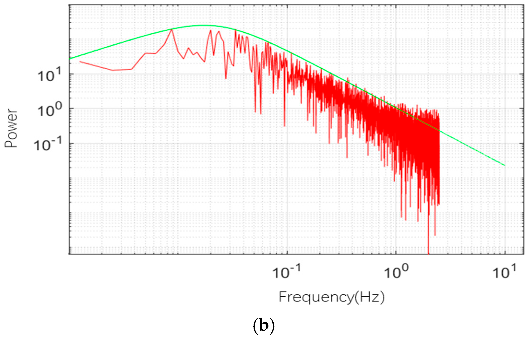
This study employs Computational Fluid Dynamics (CFD) and wind velocity time-history simulation to analyze the impact of wind loads on a wall-climbing inspection robot used on gantry cranes. The wall-climbing robot and shipyard gantry crane models were developed using SolidWorks software. Furthermore, an ANSYS-based coupled Finite Element (FE) model of the wind–gantry crane–wall-climbing inspection robot system was constructed. The analysis results indicate that wind loads primarily concentrate on the upper portion of the robot’s second platform, with a maximum pressure of 1316 Pa observed above the front section of the vehicle, where a positive pressure zone is present, and a negative pressure zone appears on the windward side. This highlights the need for structural optimization of the robot. A wind velocity time history and wind speed spectrum simulation program was developed in MATLAB, and the simulated wind speed spectrum was compared with the Davenport wind speed spectrum to validate simulation reliability. The simulated wind velocity time history was then converted to wind pressure and applied to the robot’s frame, both before and after the improvements. The analysis results demonstrate that under fluctuating wind influence, the improved robot frame exhibits reduced displacement compared to the original design, indicating better dynamic stability. Lastly, modal analysis reveals that the first six natural frequencies of the frame, with a maximum of 1679 Hz, are significantly different from the motor impact frequency, ensuring that resonance will not occur.


