Article

Analysis of Impact of Control Strategies on Integrated Electric Propulsion System Performance During Icebreaking Process

1
State Key Laboratory of Ocean Engineering, Shanghai Jiao Tong University, Shanghai 200240, China
2
Institute of Power Plants and Automation, Shanghai Jiao Tong University, Shanghai 200240, China
*
Author to whom correspondence should be addressed.
J. Mar. Sci. Eng. 2024, 12(10), 1888; https://doi.org/10.3390/jmse12101888
Submission received: 7 September 2024 / Revised: 16 October 2024 / Accepted: 18 October 2024 / Published: 21 October 2024
(This article belongs to the Section Ocean Engineering)

Abstract

:
Developing an efficient power system is an important way for icebreakers to respond to high maneuverability and strong fluctuation loads under icebreaking conditions. The performance of power systems under short-period, regularly fluctuating load-sea conditions has been intensively studied. However, the performance of the power system in the face of a long-period, stochastic multi-frequency fluctuation icebreaking process has not been fully explored, especially the parameter uncertainty and battery cycle life. In this study, an integrated electric propulsion system with an optimal control strategy is suggested for improving the power system’s dynamic performance and battery cycle life. First, an energy flow model with a diesel–electric unit as the main body and coupled energy storage system/hybrid energy storage system has been constructed. A comparative analysis of rule-based and optimization-based energy management strategies has been performed, and an optimized strategy with dynamic programming as global regulation at the upper level and model predictive control at the lower level is suggested to integrate the slow and fast dynamic powers and achieve adaptability to strong fluctuation loads. In this control strategy, the uncertainties of energy storage system/hybrid energy storage system parameters have been introduced to eliminate their impact on the system performance. Then, the icebreaking process with multi-frequency fluctuation has been simulated, and the hybrid energy storage system with battery and supercapacitor is recommended to reach multi-objective with the lowest power fluctuation of diesel–electric unit, highest efficiency, and the minimum battery degradation. Finally, the fuel oil consumption and emissions of the hybrid energy storage system have been discussed, and the optimized strategy can save fuel oil by up to 5.33% and reduce the CO2 emission by 22% during the icebreaking process, exhibiting great potential in the environmental friendliness and significant advantages in terms of low fuel oil consumption.

1. Introduction

With the gradual improvement of the availability of Arctic shipping routes, the development of Arctic maritime transportation has become an essential element for global trade [1]. However, due to the long-term presence of sea ice in the Arctic shipping route, the icebreaker is the key equipment to open up channels through the ice-covered water to ensure smooth maritime transport flows [2]. Due to the complex sea conditions of the Arctic shipping routes, the icebreakers will encounter pulse and periodic loads during the icebreaking process [3,4]. These strong nonlinear loads will cause drastic and frequent power fluctuations [5], leading to various problems, such as high fuel oil consumption, exhaust emission, and noise, and even resulting in the power system failure [6]. Hence, developing a safe, efficient, and environmental power system is very necessary for the icebreakers.
The power system of an icebreaker in service is mainly diesel–electric units, of which the diesel generator sets continuously provide power during the mission voyage. However, there are two shortcomings in the port and polar regions. First, the response scale of the diesel–electric unit is too large to provide a rapid change in the load power, and the power system is unable to supply power in a short period of time, resulting in a loss of power grid for the entire ship. In addition, the frequent power fluctuations can bring high fuel oil consumption and emissions issues. As known, the emission regulations have become increasingly stringent, and the International Maritime Organization (IMO) has set a carbon emission target for the shipping industry, i.e., a 40% reduction in carbon emission intensity by 2030 based on 2008, and net-zero carbon emissions around 2050 [7]. With the melting of Arctic glaciers, the emission restrictions in the Arctic region may become much stricter, forcing the icebreakers to improve the traditional diesel–electric power mode. Among all the optimization schemes, introducing an energy storage device is one of the important ways for the peak cutting, valley filling, emission reducing, and performance improving of the icebreaker power system.
An energy storage system (ESS) with a battery has been developed rapidly in the diesel–electric propulsion system due to its great potential in energy saving, emission reducing, and power responding. Georgescu et al. [8] concluded that ESS is especially helpful to load the engine power for gas engine systems with insufficient power response speed. Also, the liquefied natural gas (LNG)-fueled engine combined with ESS has been found to contribute to maintaining the power system at a high load with high fuel oil efficiency and low CO2 emissions [9]. A very recent study [10] showed that the addition of a battery can significantly stabilize the power output from diesel generators with a maximum fuel oil savings of 6.9–8.8%. However, it is noteworthy that the stable operation of diesel–electric units results in the batteries taking on more power fluctuations, exacerbating the aging of the batteries and affecting their service life and power output capability [11]. Therefore, the hybrid energy storage system (HESS) [12] combining different energy storage devices to leverage their complementary characteristics is an efficient and effective system solution.
Battery with supercapacitor (SC) is one of the most widely used HESS [13], which has been explored in hybrid electric vehicles and ships. Battery, as an electrochemical device, has high energy but low power density, which is suitable for low-frequency power fluctuations. In comparison, SC stores energy in an electric field, with a higher power density and fast dynamic response to support the high-frequency power load [14]. However, most studies in the literature neglected the cycle life of energy storage elements, which is indeed unavoidable during the use process. The service life of SC can be up to ten years or more [15], which satisfies the ship’s requirement and can be ignored. Nevertheless, since the battery involves a series of complex reactions, its cycle life is very short and the recharge rate is limited [16]. As the battery’s capacity degrades, its internal resistance increases notably, leading to increased losses and power tracking errors [17]. Therefore, it is urgent to quantitatively evaluate the performance of HESS considering the battery degradation characteristics for the icebreakers.
The combination of battery and SC can provide complementarity in terms of increased efficiency, prolonged cycle life, reduced size, and cost in the icebreaking process. However, the effectiveness of HESS highly relies on the allocation of power loads and multiple energy sources. Acanfora et al. [18] used the Hilbert transform decomposition of load demand to establish specific frequency thresholds in order to choose the more adequate storage system for the leveling action under various sea state conditions. Zhang et al. [19] applied the adaptive low-pass filter to optimize the energy loss for a hybrid power system consisting of a diesel–electric unit and a HESS, and the HESS energy loss has been saved by 14.55%. Considering the investment cost and battery degradation minimization, Li et al. [20] proposed an energy management strategy (EMS) for the marine HESS based on adaptive segmentation and frequency control. EMS is indispensable for the efficient application of HESS.
Two types of EMS have been commonly applied for ships, i.e., rule-based and optimization-based. The rule-based EMS builds on previous experiences and expert knowledge. Wang et al. [21] have applied the rule-based EMS to control the power flow for a hybrid diesel engines/batteries/shore power system. However, the ship power demand is dynamically updated and the rule-based EMS makes it hard to find the optimal solution [13]. In contrast, the optimization-based EMS is much more effective for multi-energy ships, as it solves the minimization of the cost function to achieve energy management within the system constraints. Tona et al. [22] used dynamic programming (DP)-based EMS to schedule the electrical power flows based on the load demand forecasting data. Moreover, the model predictive control (MPC)-based EMS has been found to be an effective EMS for ships [23]. Antonopoulos et al. [24] designed anMPC controller that significantly reduces the fuel oil consumption in the hybrid power system. However, the above studies have not considered the impact of HESS parameter uncertainties, which is significant for energy loss and power output. As we know, the battery and SC voltages vary with the state of charge (SOC) and can be over 100% [25], especially for the energy storage devices that always operate under extreme SOC conditions caused by the highly nonlinear loads. In order to address these major impact uncertainties, Hou et al. [26] first proposed an adaptive MPC method with the parameter uncertainty to realize the optimal allocation of power and dynamic response of the HESS. Their results also confirmed that the parameter uncertainty can significantly affect the system performance of HESS. Notably, in [26], the major effort is to discuss the impact of parameter uncertainties on the power system performance under the sea state with regular fluctuating loads in a short period. However, the condition of polar navigation is a long period and the icebreaking process is characterized by random multi-frequency fluctuations. To the best of the authors’ knowledge, the impact of HESS parameter uncertainties on the energy loss and power dynamic tracking for the icebreakers has not been well explored. In order to deal with these issues, the main contributions of this research are summarized in the following:
  • A DP-MPC energy management strategy is suggested to optimize the power distribution for the integrated electric propulsion system of an icebreaker to improve the adaptability to strong fluctuation loads.
  • The parameter uncertainties of battery and supercapacitor have been introduced in the DP-MPC strategy to emphasize the impact on system performance during the icebreaking process.
  • A hybrid energy storage system with battery degradation is introduced to reduce the battery energy losses.
The paper is organized as follows: The modeling of the system is presented in Section 2. Section 3 presents the rule-based EMS and the improved DP-MPC EMS. Section 4 shows the validation of the system model. Section 5 compares the results of rule-based and DP-MPC strategies. Section 6 draws the main conclusions of this study.

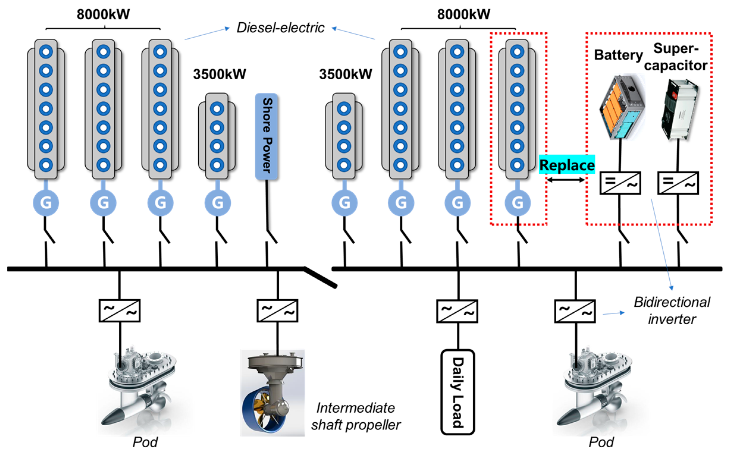
2. Structure and Modeling of Integrated Electric Propulsion System

The power system of the prototype icebreaker is equipped with six sets of 8000 kW diesel–electric and two sets of 3500 kW diesel–electric as power sources, two sets of 10 MW pods, and one set of 17 MW intermediate shaft propeller for propulsion [27]. Taking into account the layout of the prototype ship, cabin volume, and power satisfaction, an ESS/HESS is introduced to replace one of the 8000 kW diesel–electric sets to obtain an integrated electric propulsion system, as shown in Figure 1. In addition to the power sources and propulsion, the system includes bidirectional inverters for the conversion of energy and daily loads consisting of other electrical loads on board. In this study, the daily load is taken as 3.413 MW [28].
The focus of this study is on the energy management of the icebreaker power system and the impact of battery degradation, and thus this section only introduces the power source modeling and load estimation in detail.

2.1. Model of Diesel–Electric Unit

Generally, as the diesel engine is used for power generation, its speed remains constant, and the power varies with the load of the generator. From a control perspective, the diesel engine could be simplified into three parts: the controller [29], the actuator, and the operating components. The corresponding transfer function is described as follows:
G s = T s K 1 1 + T 1 s 1 1 + T 2 s
where T ( s ) represents the PID law of action; K 1 indicates the actuator gain factor; T 1 is the time constant of the actuator; T 2 is the delay time for diesel engines; and s denotes the complex frequency.
The diesel engine and generator are connected by torque. To simplify the calculation, the efficiency of the generator is taken as 0.96. The pollutant emissions due to the oil combustion during the operation of diesel–electric sets can be calculated by the formula in Table 1, which adapted from literature [30].

2.2. Model of ESS/HESS Element

The equivalent circuit model (ECM) is one of the effective models to model the battery and SC states [31], which has been widely used for performance evaluation in system simulation [32]. A detailed model can more accurately capture the system dynamics but with the high computational cost, and thus a simplified model with low computational cost is preferred. However, an oversimplified model cannot capture key dynamics. In order to balance the accuracy and dynamic performance of the calculation, a second-order resistor–capacitor (RC) ECM [33] is selected to model the battery state, as shown in Figure 2a.
The parametric model of the second-order RC ECM can be expressed as follows:
U b 1 ˙ U b 2 ˙ = 1 R b 1 C b 1 0 0 1 R b 2 C b 2 U b 1 U b 2 + C b 1 C b 2 I b U t b = U b I b R b U b 1 U b 2
where U b 1 ,   R b 1 , a n d   C b 1 are the voltage, polarization resistance, and polarization capacitance across the RC network I, respectively, V , m Ω , m F ; U b 2 ,   R b 2 , a n d   C b 2 are the voltage, polarization resistance, and polarization capacitance across the RC network II, respectively, V , m Ω , m F ; U b is the open circuit voltage of the battery, V ; R b is the internal resistance of the battery, m Ω ; U t b is the operating voltage of the battery, V ; and I b is the operating current of the battery, A . So, the output power of the battery is calculated as P b = U t b I b .
Since the battery charging and discharging processes can lead to a certain amount of energy loss, a battery degradation model has been implemented [32], and it is the combined effect of current intensity and current duration, written as follows:
E b _ l o s s = α E b α = 1 2364 exp I r a t e 2525 A h t h r o u g h p u t
where E b _ l o s s is the battery energy loss due to the degradation, k W h ; E b is the initial energy of the battery, k W h ; α is the degradation rate, % ; I r a t e is the battery current rate expressed as its current divided by its capacity; and A h t h r o u g h p u t is the ampere-hour through-put defined as the product of current and time, Ah.
The Stern ECM has been widely used to model the supercapacitor, while it ignores the effect of SOC variation on the internal capacitance discharge characteristics [34]. Based on the data in [35], the variation in SC voltage with SOC can be over 100%, which is significant to the HESS parameter uncertainties. Therefore, the variable capacitance concept [35] has been introduced in this study, as shown in Figure 2b, and the voltage of SC is calculated as follows:
U s c = 1 C t 0 t I s c d t + U U t = U s c I s c R s c
where U s c is the open-circuit voltage of SC, V ; U is the compensation term for voltage variation with SOC, V ; C is the capacitance of the ECM, F ; R s c is the internal resistance of SC, m Ω ; U t is the operating voltage of SC, V ; and I s c is the operating current of SC, A . So, the output power of SC can be expressed as P S C = U t I S C .
Based on the above description, the discretized ESS/HESS model can be expressed as follows:
S O C b k + 1 S O C s c k + 1 = 1 0 0 1 S O C b k S O C s c k 1 E b 0 0 1 E s c P b k P s c k
where S O C b k + 1 and S O C s c k + 1 denote the SOC of battery and SC at time step k + 1, respectively; P b k and P s c k are the output power of the battery and supercapacitor at time step k, respectively; and E b   and E s c are the current energy of the battery and SC, k W h , respectively.

2.3. Model of Bidirectional Inverter

Bidirectional inverters are capable of converting DC and AC power to each other. Ovrum et al. [36] have analyzed the sensitivity of fuel oil consumption to inverter efficiency. The results showed that higher efficiency can lead to lower fuel oil consumption, but the impact is minimal. As the efficiency increases from 95% to 99%, the maximum fuel oil consumption difference is only 1.2%. Zhang et al. [37] modeled the inverter as a 99% efficient energy conversion device and concluded that it was sufficient to validate the fuel-saving capability of the proposed strategy. In this study, the bidirectional inverter is modeled as a fixed energy loss of 98% efficiency.

2.4. Model of Propulsion Power

Due to the scarcity of practical application cases and data in the field of icebreakers, relevant icebreaking standard working conditions have not yet been established. In this paper, the characterization of the propulsion system is carried out on the basis of the icebreaking condition commonly adopted in the literature [38], and the transient power of the propulsion load is derived from an equal proportional conversion based on a total target propulsion power of 37 MW.

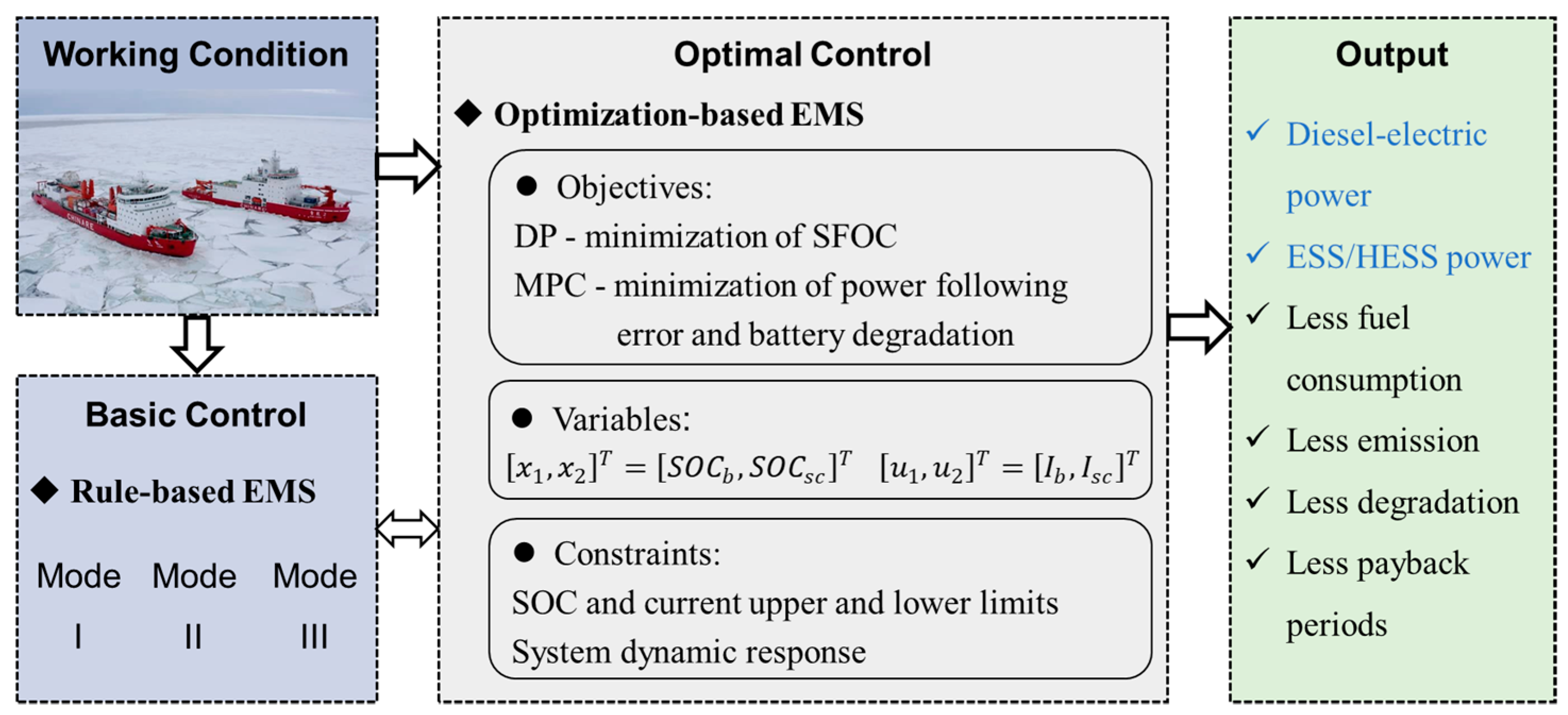
3. Control and Optimization

The performance of an integrated electric propulsion system is highly dependent on the EMS, which coordinates and controls the power output and sources according to the system state, power demand, and the transient response capability of power sources. In this section, the rule-based EMS is first introduced and then the optimization-based EMS is described. The procedure of the control and optimization for the power system is presented in Figure 3. All the controls and simulations are realized through Matlab/Simulink (R2022b).

3.1. Rule-Based EMS

The rule-based EMS delineates the system operating modes for power distribution and control. Figure 4 illustrates the rule control flow of the integrated electric propulsion system. In the figure, P l denotes the load demand power, P g denotes the output power of the running diesel genset, P g . a d d denotes the output power of the newly started diesel genset, and P b denotes the output power of the ESS.
Three operating modes are classified based on the efficient operating interval of the diesel–electric set (75% to 90% load), and the charging and discharging limits of the ESS/HESS are set as 20% to 90% SOC [39] at the conditions without the start and stop of diesel–electric sets. Different operating modes correspond to different power source responses, and the system constraints are the same as those described in Section 3.3. Specifically:
  • Mode I: As the load power is lower than the minimum power of the diesel–electric sets, the diesel–electric sets operate at the minimum power, i.e., 75% load, and the excess energy is absorbed by the ESS. As the SOC of the ESS is higher than the threshold (90%), the diesel–electric sets operate at load reduction.
  • Mode II: As the load power is in the optimal operating range of the diesel–electric sets, i.e., 75–90% load, the power demand is fully provided by the diesel–electric sets.
  • Mode III: As the load power is higher than the maximum power of the operating diesel–electric sets, the diesel–electric sets operate at the maximum power, i.e., 90% load, and the shortfall power is provided by the ESS. When the SOC of the ESS is below the threshold (20%), the standby diesel–electric set is turned on to take up the power difference and charge the ESS.
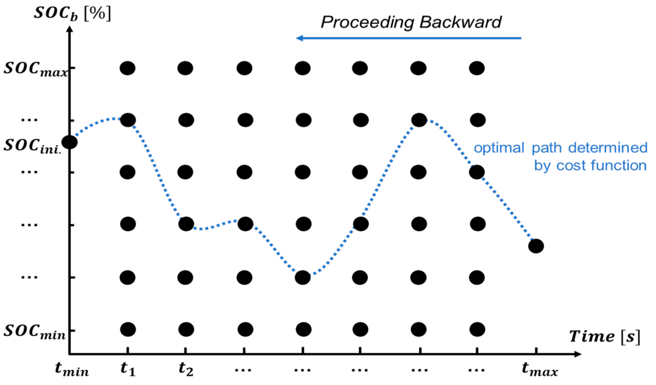
3.2. DP-Based EMS

The DP algorithm is a global optimization method that typically uses backward recursion to solve the optimization problem [40]. It can be used for the energy distribution of the diesel–electric sets, whether it is coupled with ESS or HESS. The graphical representation of the algorithm adopted in this paper is shown in Figure 5. Based on the sensitivity study, the computational time step is set as 1/1500 s, and the SOC state is discretized into 35,000 segments. The optimal SOC trajectory is determined by this method, and the energy distribution of diesel–electric sets is determined as follows.
The cost function (J) is defined as the minimum specific fuel oil consumption (SFOC):
J = S F O C
Subject to the constraints:
S O C b _ m i n S O C b k S O C b _ m a x I b _ m i n I b ( k ) I b _ m a x
S O C b _ i n i . _ D P = S O C b _ i n i . _ R u l e , S O C b _ e n d _ D P = S O C b _ e n d _ R u l e
where S O C b _ m i n and S O C b _ m a x are the lower and upper boundaries of the SOC; I b _ m i n and I b _ m a x are the lower and upper boundaries of the output currents; and S O C b _ i n i . _ D P , S O C b _ e n d _ D P , S O C b _ i n i . _ R u l e , and S O C b _ e n d _ R u l e denote the SOC of the battery at the initial and end states in DP-based and rule-based EMS, respectively. In order to evaluate the advantage of the DP-based method, the initial and end SOCs in both the DP-based and rule-based EMS are set as the same, as shown in Equation (8).

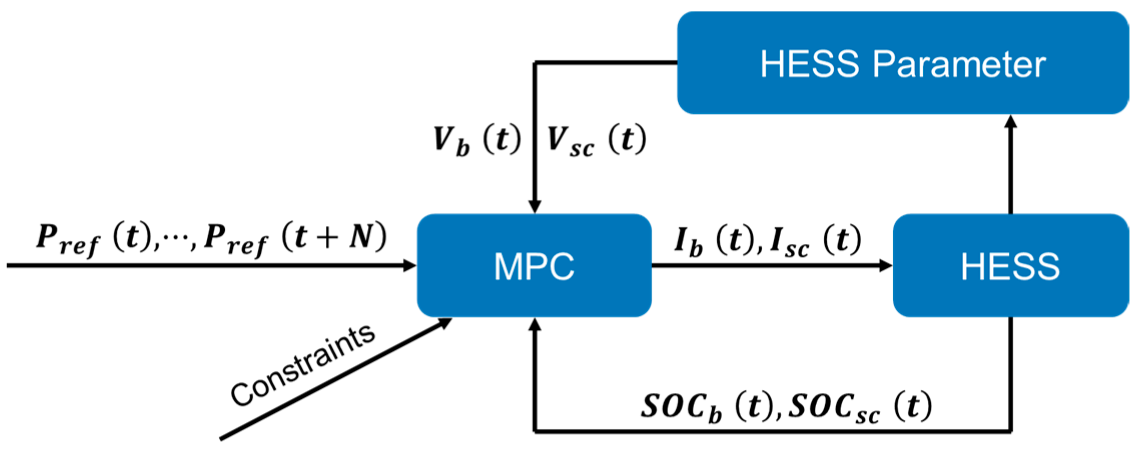
3.3. Model Predictive Control

During the icebreaking process, the propulsion load contains multi-frequency fluctuations due to irregular ice loads and propeller rotation, which can lead to major parameter uncertainties, such as voltage and current. This is very significant for the ESS only with a single energy storage device, easily compromising and reducing its cycle life. The typical MPC method [37] ignores the impact of parameter uncertainties, making it difficult to track the energy loss and power load. Therefore, an improved MPC with parameter uncertainties is suggested in this study, as shown in Figure 6, in which the voltage of the HESS will update accordingly with the state of SOC, and the HESS voltage is added as a feedback term to the controller, taking into account the impact of HESS parameter uncertainties to improve the control accuracy of MPC. Herein, the SOC of the HESS is selected as the state quantity, and the output current of the HESS is the control quantity. As the state of SOC changes, the voltage of the HESS will update accordingly, which affects the power output. Therefore, the HESS voltage is added as a feedback term to the controller, taking into account the impact of HESS parameter uncertainties to improve the control accuracy of MPC.
The cost function of the improved MPC contains two terms, as expressed by Equation (9). The first term on the right side is to reduce the rate of battery degradation, and the second term is to minimize the tracking error of the HESS power, i.e., the output power of the battery and the supercapacitor needs to meet the load power demand.
J = 1 2 i = 1 N p [ λ l o s s α b + λ t r a c k ( P r e f . P b P s c ) 2 ]
Subject to the constraints:
S O C b _ m i n S O C b k S O C b _ m a x S O C s c _ m i n S O C b ( k ) S O C s c _ m a x I b _ m i n I b k I b _ m a x I s c _ m i n I s c ( k ) I s c _ m a x
where λ l o s s and λ t r a c k are weighting factors to put different emphasis on each item; α b is the degradation rate; and P r e f . is the reference power from DP. Equation (10) characterizes the input and state constraints of the system.
The following assumptions are made in the modeling of this study: there is no response delay for each energy system during energy scheduling; the control system is able to control the output of the energy system in accordance with the scheduling strategy; and the lifetime loss of the battery is attributed to the joint result of the magnitude of the charging and discharging currents, charging and discharging rate, and charging and discharging power.

4. Case Study

4.1. Specific Fuel Oil Consumptions

The diesel engine includes a 16-cylinder V-type engine and a 7-cylinder L-type engine. According to the fuel oil consumption data provided by the diesel engine manual, the fuel oil consumption curve was obtained through the spline fitting [41], as shown in Figure 7, which is consistent with the actual operating conditions.

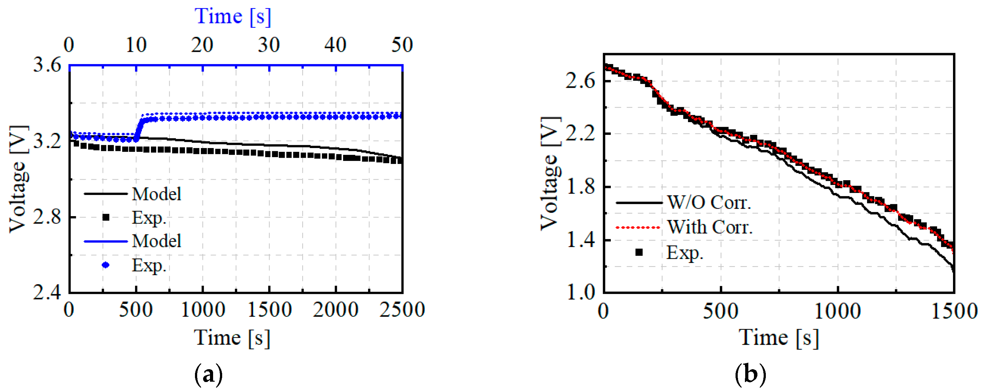
4.2. HESS Model Validation

The lithium-ion battery [39] and supercapacitor from Maxwell are used in this study, and their main parameters are listed in Table 2.
In order to verify the accuracy of the simulation model of the ESS/HESS, the experimental results of a battery [42] and supercapacitor [35] are simulated, and the compared results are displayed in Figure 8. As shown, the estimation error is below 5%, which meets the requirement of prediction accuracy. Figure 8b compares the predictions with and without the variable capacitor proposed in this study (Equation (4), ΔU = −0.0028 × SOC + 0.2469). Apparently, as time progresses, considering the impact of HESS parameter uncertainty can significantly improve the prediction accuracy.
According to the experimental identification of the discharge characteristics [35,42], the charging and discharge characteristics of the ESS/HESS are assumed to be the same in this study. Meanwhile, the differences between the monomers inside the ESS/HESS are ignored, and their states are assumed to be consistent, which is uniformly affected by the charging and discharging power.

5. Results and Discussions

In order to emphasize the benefits of the ESS/HESS to the diesel–electric sets as well as the optimization strategy for the icebreaker, a typical icebreaking process with multi-frequency fluctuations has been simulated, and the power demand within 1500 s is shown in Figure 9. In the simulation, the cases with diesel–electric unit (case 1), ESS (case 2), and the HESS (case 3) have been performed, and the distribution of energy sources is separately controlled by the rule-based and DP-based modes. The operating parameters of the diesel generator and the size of ESS/HESS are listed in Table 3.

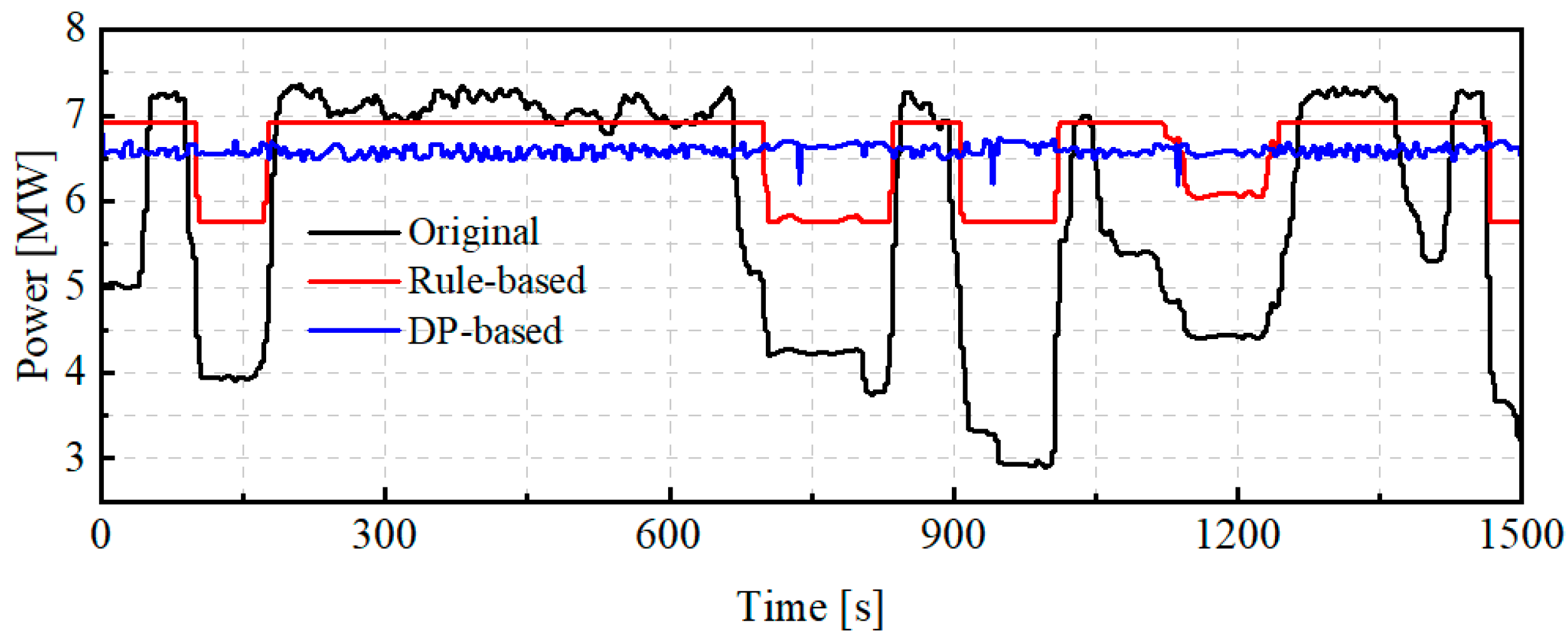
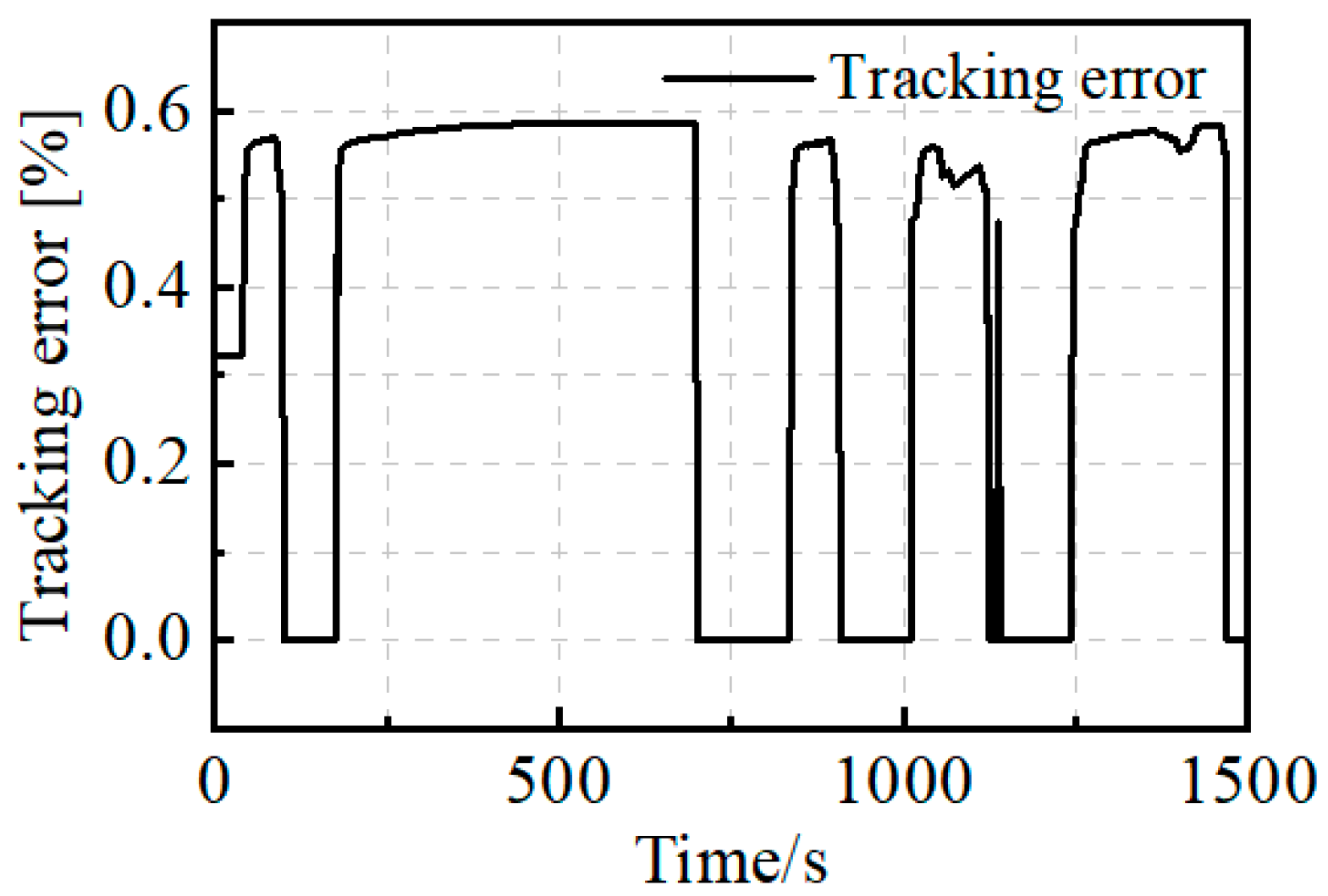
5.1. System Dynamic Performance

To mitigate the power fluctuation of diesel–electric units with high efficiency, the ESS (case 2) separately controlled by the rule-based and DP-based modes has been introduced and compared with the original power system (case 1) in this section. In the simulation, the initial SOC of both battery and supercapacitor is set as 80%, and the dynamic response of the diesel–electric unit is shown in Figure 9. The black line indicates the power provided by the diesel engine in the pure diesel–electric mode (case 1), which also represents the original power demand. The red and blue lines represent the powers supplied by the diesel–electric under the rule-based and DP-based control modes, respectively. Apparently, with the introduction of energy storage devices, the fluctuation of the power response of the diesel–electric unit is significantly reduced under any control mode, and the reduction extent driven by the DP-based mode is much more pronounced than the rule-based mode. Moreover, although the diesel–electric unit has already operated within the effective interval (75~90%) under the rule-based control, its efficiency (86~87%) becomes higher under the DP-based control. The DP-based control is more inclined to maintain the power of the diesel–electric unit at a specific level and reduce the fluctuation due to external load changes.
In order to reduce the battery fluctuation and enlarge its cycle life, the HESS has been introduced, i.e., case 3 in Table 3. Figure 10 shows the dynamic response of the battery and supercapacitor with the rule-based and DP-MPC modes. Herein, MPC is the secondary control strategy to regulate the battery and supercapacitor after DP application. The solid line in the figure indicates the result controlled by DP-MPC and the dotted line is the result controlled by the rule-based mode. The positive value indicates the discharging process and the negative value is the charging process. Based on the results, it is seen that compared to the results of rule-based, the battery under the DP-MPC strategy undertakes more power difference, and higher charging and discharging power. Moreover, under the DP-MPC strategy, the supercapacitor plays the role of local high-power smoothing, whereas the rule-based results show that the HESS varies drastically at high power, especially at 1300 s.

5.2. Battery Degradation Rate

Figure 11 illustrates the degradation rate of the battery in ESS and HESS with different controlled strategies, taking into account the charging and discharging rate of the battery and the load-carrying capacity. In the figure, the green solid lines and black dotted lines indicate the degradation of the batteries controlled by the rule-based mode in ESS and HESS, respectively. Since the batteries bear the major power difference in the rule-based control, their degradation rates are roughly comparable in both the ESS and HESS methods. The red and blue solid lines separately represent the battery performance controlled by optimization methods in ESS and HESS. Since the power fluctuation of the diesel generator is greatly mitigated with the DP-MPC strategy, the battery is subjected to larger fluctuating loads, leading to its highest degradation rate. In the HESS, the introduction of a supercapacitor with the MP strategy can reduce the battery degradation rate by about 4.39%. Noteworthy, in any energy mode, the degradation rate of the battery controlled by the optimization method is higher than that with the rule-based method, this is because the battery carries more power difference.
The tracking error of the HESS under the DP-MPC strategy is shown in Figure 12. Taking the HESS load power as a reference, the tracking error at any moment remains below 0.6% for the typical icebreaking process with multi-frequency fluctuations. Therefore, the power control of the HESS can satisfy the load power requirement for the typical icebreaking process with multi-frequency fluctuations.

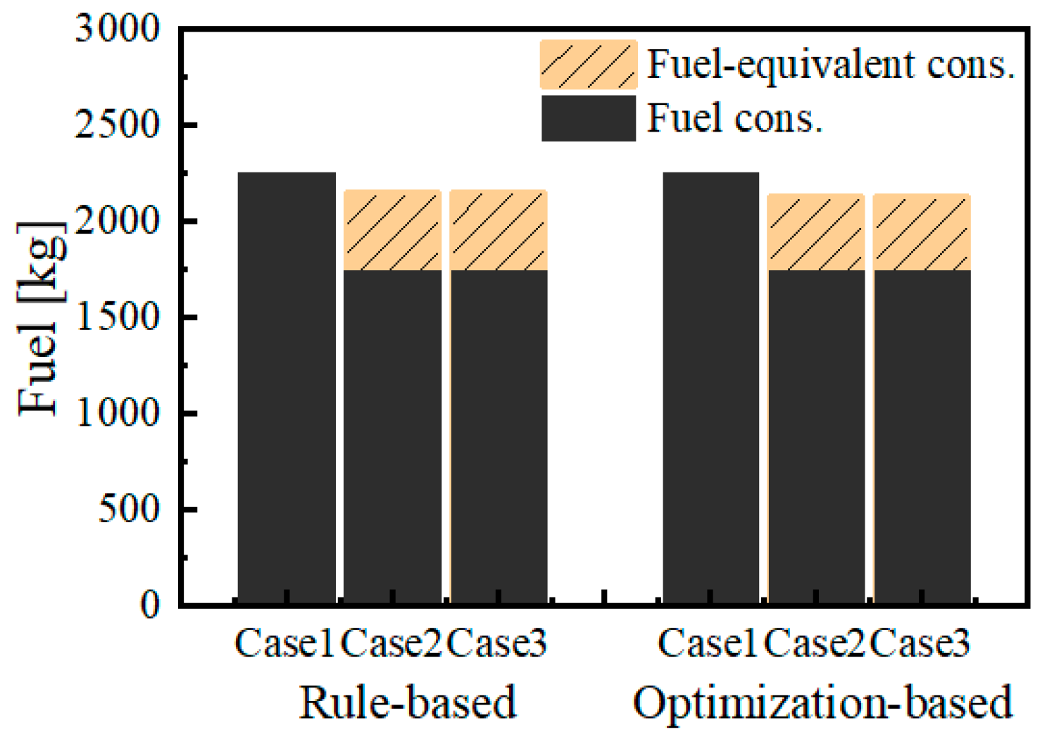
5.3. Fuel Oil Consumption and Emission

The results of fuel oil consumption and emissions under the icebreaking process are shown in Figure 13 and Figure 14, respectively. In this study, the equivalent fuel oil consumption caused by the energy storage devices in ESS/HESS has been considered, as represented by the yellow stripe bar in Figure 13, while their resulting emission has been neglected. As shown in Figure 13, both ESS and HESS have saved the specific fuel oil consumption, and the optimization-based method is more effective than the rule-based method, but not very significant. In Figure 14, the emissions of CO2, NOx, SOx, and PM have been compared between the original diesel–electric system, rule-based (case 2), and optimization-based (case 2). As shown, CO2 shows the most significant reduction of around 22% compared with the original diesel–electric system, and the other three emissions drop slightly less than this. By comparing the rule-based and optimization-based methods, it is found that the control strategy shows little impact on both fuel oil consumption and emissions (Figure 13 and Figure 14) even though they have a large difference in dynamic performance, as presented in Figure 9 and Figure 10. It is speculated that the fuel oil consumption is not only related to the transient load of the engine, but also to the sustained power output time.
In terms of system economics, the system under the DP-MPC control strategy is the most affordable. When the battery degradation rate reaches 20%, the entire battery is commonly recognized as end-of-life. Even though the battery degradation rate of the DP-MPC control strategy is significantly higher than the rule-based one, the fuel oil cost saved ( J f u e l = m × P r i c e f u e l ,where ∆m is the fuel oil saved under the DP-MPC control strategy) is about 5.5 times higher than the cost caused by battery degradation ( J d e g r a d a t i o n = E b _ l o s s × P r i c e b / 20 % ) in a 1500s icebreaking process based on the ratio of J f u e l to J d e g r a d a t i o n . And, the system with HESS presents a lower battery degradation rate than the ESS and shows a better economy.

6. Conclusions

In order to improve the power system dynamic performance and reduce battery degradation, a joint optimization method based on DP and MPC is designed in this study, and a comparative study has been performed based on the rule-based control strategy. The DP is used in the upper layer to seek the optimal energy distribution between the diesel–electric unit and the ESS, while the MPC in the lower layer ensures the power following of the HESS and prolongs the battery life. During the implementation of the control strategy, the uncertainty of the parameters is introduced to eliminate the effect on the system.
It is shown that the introduction of DP reduces fuel oil consumption by 5.33% compared to the rule-based result of 4.30% under icebreaking conditions with multi-frequency fluctuations. Meanwhile, the lower layer MPC can effectively ensure the power tracking of the HESS and reduce the degradation rate of the battery by nearly 4.39% compared to that of DP alone. Meanwhile, the integrated electric propulsion system with HESS under the DP-MPC control strategy shows better economy and environmental friendliness.
As the icebreaker is primarily engaged in polar voyages, a high-power class main energy source unit is essential. Equipping auxiliary energy sources such as hybrid energy systems can effectively reduce the load fluctuation of the main energy source unit. Hybrid energy systems consisting of batteries and supercapacitors may be preferred in the future and show great potential for reducing battery losses. The work conducted in this study can provide a reference for the design of power systems and energy management for icebreakers. Based on the research work in this study, the next work will focus on the deployment of energy management strategies on real controllers, especially in terms of optimized strategies.

Author Contributions

Conceptualization, L.L., P.Y. and T.L.; methodology, L.L.; software, L.L.; validation, L.L., P.Y. and S.W.; formal analysis, P.Y.; investigation, L.L.; resources, P.Y.; data curation, S.W.; writing—original draft preparation, L.L.; writing—review and editing, P.Y. and S.W.; visualization, P.Y. and S.H.; supervision, P.Y.; project administration, P.Y.; funding acquisition, P.Y. All authors have read and agreed to the published version of the manuscript.

Funding

This research was funded by the National Natural Science Foundation of China (52371330) and the Technology Plan Project of Shanghai (22dzl204403).

Institutional Review Board Statement

Not applicable.

Informed Consent Statement

Not applicable.

Data Availability Statement

The original contributions presented in the study are included in the article, further inquiries can be directed to the corresponding author.

Acknowledgments

The authors also gratefully acknowledge the helpful comments and suggestions of the reviewers, which have improved the presentation.

Conflicts of Interest

The authors declare no conflicts of interest.

Nomenclature

IMOInternational Maritime Organization
ESSEnergy storage system
HESSHybrid energy storage system
SCSupercapacitor
EMSEnergy management strategy
DPDynamic programming
MPCModel predictive control
SOCState of charge
ECMEquivalent circuit model
RCResistor–capacitor
SFOCSpecific fuel oil consumption

References

  1. Theocharis, D.; Pettit, S.; Rodrigues, V.S.; Haider, J. Arctic shipping: A systematic literature review of comparative studies. J. Transp. Geogr. 2018, 69, 112–128. [Google Scholar] [CrossRef]
  2. Progress of China’s Polar Science and Technology Innovation Work. Available online: https://aoc.ouc.edu.cn/2021/1012/c9821a352702/page.htm (accessed on 12 December 2023).
  3. Bjørnø, J.; Berg, M.V.D.; Lu, W.J.; Skjetne, R.; Lubbad, R.; Løset, S. Performance quantification of icebreaker operations in ice management by numerical simulations. Cold Reg. Sci. Technol. 2022, 194, 103435. [Google Scholar] [CrossRef]
  4. Zambon, A.; Moro, L.; Oldford, D. Impact of different characteristics of the ice–propeller interaction torque on the torsional vibration response of a Polar-Class shaftline. Ocean Eng. 2022, 266, 112630. [Google Scholar] [CrossRef]
  5. Long, F.; Fang, B.; Yang, C. State-of-the-Art of polar icebreaker pod propulsion system. Ship Boat 2023, 34, 154–160. [Google Scholar]
  6. Lindstad, H.G.; Psaraftis, H.N.; Sandaas, I.; Strømman, A.H. Maritime shipping and emissions: A three-layered, damage-based approach. Ocean Eng. 2015, 110, 94–101. [Google Scholar] [CrossRef]
  7. IMO Revises Strategy to Achieve Net-Zero Emissions from Global Shipping by 2050. Available online: https://news.un.org/zh/story/2023/07/1119527 (accessed on 9 January 2024).
  8. Georgescu, I.; Godjevac, M.; Visser, K. Efficiency constraints of energy storage for on-board power systems. Ocean Eng. 2018, 162, 239–247. [Google Scholar] [CrossRef]
  9. Pang, B.; Liu, S.; Zhu, H.; Feng, Y.; Dong, Z. Real-Time Optimal Control of an LNG-Fueled Hybrid Electric Ship Considering Battery Degradations. Energy 2024, 296, 131170. [Google Scholar] [CrossRef]
  10. Ghimire, P.; Zadeh, M.; Thapa, S.; Thorstensen, J.; Pedersen, E. Operational Efficiency and Emissions Assessment of Ship Hybrid Power Systems with Battery; Effect of Control Strategies. IEEE Trans. Transp. Electrif. 2024, 1. Available online: https://ieeexplore.ieee.org/document/10433233 (accessed on 27 June 2024). [CrossRef]
  11. Huang, J.; An, Q.; Zhou, M.; Tang, R.; Dong, Z.; Lai, J.; Li, X.; Yang, X.G. A self-adaptive joint optimization framework for marine hybrid energy storage system design considering load fluctuation characteristics. Appl. Energy 2024, 361, 122973. [Google Scholar] [CrossRef]
  12. Ostadi, A.; Kazerani, M. A comparative analysis of optimal sizing of battery-only, ultracapacitor-only, and battery-ultracapacitor hybrid energy storage systems for a city bus. IEEE Trans. Veh. Technol. 2014, 64, 4449–4460. [Google Scholar] [CrossRef]
  13. Inal, O.B.; Charpentier, J.F.; Deniz, C. Hybrid power and propulsion systems for ships: Current status and future challenges. Renew. Sustain. Energy Rev. 2022, 156, 111965. [Google Scholar] [CrossRef]
  14. Hou, J.; Sun, J.; Hofmann, H. Adaptive model predictive control with propulsion load estimation and prediction for all-electric ship energy management. Energy 2018, 150, 877–889. [Google Scholar] [CrossRef]
  15. Zhang, L.; Hu, X.; Wang, Z.; Sun, F.; Deng, J.; Dorrell, D.G. Multi-objective optimal sizing of hybrid energy storage system for electric vehicles. IEEE Trans. Veh. Technol. 2018, 67, 1027–1035. [Google Scholar] [CrossRef]
  16. Yan, D.; Lu, L.; Li, Z.; Feng, X.; Ouyang, M.; Jiang, F. Durability comparison of four different types of high-power batteries in HEV and their degradation mechanism analysis. Appl. Energy 2016, 179, 1123–1130. [Google Scholar] [CrossRef]
  17. Zou, C.F.; Zhang, L.; Hu, X.S.; Wang, Z.P.; Wik, T.; Pecht, M. A review of fractional-order techniques applied to lithium-ion batteries, lead-acid batteries, and supercapacitors. J. Power Sources 2018, 390, 286–296. [Google Scholar] [CrossRef]
  18. Acanfora, M.; Balsamo, F.; Fantauzzi, M.; Lauria, D.; Proto, D. Design of an electrical energy storage system for hybrid diesel electric ship propulsion aimed at load levelling in irregular wave conditions. Appl. Energy 2023, 350, 121728. [Google Scholar] [CrossRef]
  19. Zhang, Y.F.; Diao, L.J.; Pei, H.Y.; Ma, X.N.; Liu, S.Y.; Zhang, S.H.; Du, H.Q.; Xu, C.M. A GRNN informed ECMS-ALPF operational management strategy for reducing fuel consumption of diesel/battery/supercapacitor hybrid vehicles. Ocean Coast. Manag. 2023, 245, 106838. [Google Scholar] [CrossRef]
  20. Li, X.; Huang, J.; Zhang, J.K.; Zhou, M.; Wang, T.; Tan, X.; Lai, J.; Yang, X.G. An adaptive multi-objective joint optimization framework for marine hybrid energy storage system design considering energy management strategy. J. Energy Storage 2023, 68, 107689. [Google Scholar] [CrossRef]
  21. Wang, Z.; Chen, L.; Wang, B. Tri-Objective optimal design of a hybrid electric propulsion system for a polar mini-cruise ship. Ocean Eng. 2024, 300, 117355. [Google Scholar] [CrossRef]
  22. Tona, G.L.; Luna, M.; Piazza, M.C.; Pietra, A. Energy management system for efficiency increase in cruise ship microgrids. In Proceedings of the IECON 2019—45th Annual Conference of the IEEE Industrial Electronics Society, Lisbon, Portugal, 14–17 October 2019. [Google Scholar]
  23. Geertsma, R.D.; Negenborn, R.R.; Visser, K.; Hopman, J.J. Design and control of hybrid power and propulsion systems for smart ships: A review of development. Appl. Energy 2017, 194, 30–54. [Google Scholar] [CrossRef]
  24. Antonopoulos, S.; Visser, K.; Kalikatzarakis, M.; Reppa, V. MPC framework for the energy management of hybrid ships with an energy storage system. J. Mar. Sci. Eng. 2021, 9, 993. [Google Scholar] [CrossRef]
  25. Wang, C.; He, H.; Zhang, Y.; Mu, H. A comparative study on the applicability of ultracapacitor models for electric vehicles under different temperatures. Appl. Energy 2017, 196, 268–278. [Google Scholar] [CrossRef]
  26. Hou, J.; Song, Z.; Hofmann, H.; Sun, J. Adaptive model predictive control for hybrid energy storage energy management in all-electric ship microgrids. Energy Conver. Manag. 2019, 198, 111929. [Google Scholar] [CrossRef]
  27. Lu, W.; Zhi, L. On Power Grid Architecture of Heavy Icebreakers. Ship Boat 2023, 34, 129–136. [Google Scholar]
  28. Zhai, Y. Optimal Configuration and Simulation Research on Management Strategy of Hybrid Power System. Master’s Thesis, Beijing Jiaotong University, Beijing, China, 2016. [Google Scholar]
  29. Belyaev, M.E.; Gerasimov, D.N.; Rymalis, M.R.; Semenov, S.A. Design of diesel engine mathematical model oriented to speed control. J. Comput. Syst. Sci. Int. 2018, 57, 626–639. [Google Scholar] [CrossRef]
  30. IMO. Third IMO Greenhouse Gas Study 2014. Executive Summary and Final Report; International Maritime Organization: London, UK, 2015; pp. 176–178. Available online: https://greenvoyage2050.imo.org/wp-content/uploads/2021/01/third-imo-ghg-study-2014-executive-summary-and-final-report.pdf (accessed on 12 November 2023).
  31. Hu, X.; Li, S.; Peng, H. A comparative study of equivalent circuit models for Li-ion batteries. J. Power Sources 2012, 198, 359–367. [Google Scholar] [CrossRef]
  32. Zhu, T.; Wills, R.G.; Lot, R.; Kong, X.D.; Yan, X.D. Optimal sizing and sensitivity analysis of a battery-supercapacitor energy storage system for electric vehicles. Energy 2021, 221, 119851. [Google Scholar] [CrossRef]
  33. Lagnoni, M.; Scarpelli, C.; Lutzemberger, G.; Bertei, A. Critical comparison of equivalent circuit and physics-based models for lithium-ion batteries: A graphite/lithium-iron-phosphate case study. J. Energy Storage 2024, 94, 112326. [Google Scholar] [CrossRef]
  34. Zhang, L.; Hu, X.; Wang, Z.; Sun, F.C.; Dorrell, D.G. A Review of Supercapacitor Modelling, Estimation, and Applications: A Control/Management Perspective. Renew. Sustain. Energy Rev. 2018, 81, 1868–1878. [Google Scholar] [CrossRef]
  35. Liu, C.; Wang, Y.J.; Chen, Z.H.; Ling, Q. A variable capacitance-based modeling and power capability predicting method for ultracapacitor. J. Power Sources 2018, 374, 121–133. [Google Scholar] [CrossRef]
  36. Ovrum, E.; Bergh, T.F. Modelling lithium-ion battery hybrid ship crane operation. Appl. Energy 2015, 152, 162–172. [Google Scholar] [CrossRef]
  37. Zhang, Y.; Xue, Q.; Gao, D.; Shi, W.; Yu, W. Two-level model predictive control energy management strategy for hybrid power ships with hybrid energy storage system. J. Energy Storage 2022, 52, 104763. [Google Scholar] [CrossRef]
  38. Liu, Y.S.; Ee, F.; Feng, H.; Li, Y. Optimization of energy storage capacity of electric propulsion system for icebreaker. J. Shanghai Ship Shipp. Res. Ins. 2016, 39, 47–51. [Google Scholar]
  39. General-purpose Technology Specification for Energy Storage Cabinet. Available online: https://www.ces.org.cn/res/ces/2307/e7c3fa4d9b82e95caa1916c37da4e866.pdf (accessed on 20 December 2023).
  40. Santucci, A.; Sorniotti, A.; Lekakou, C. Power split strategies for hybrid energy storage systems for vehicular applications. J. Power Sources 2014, 258, 395–407. [Google Scholar] [CrossRef]
  41. Nuchturee, C.; Li, T.; Xia, H. Design of cost-effective and emission-aware power plant system for integrated electric propulsion ships. Mar. Sci. Eng. 2021, 9, 684. [Google Scholar] [CrossRef]
  42. Zhao, J.M. Modeling and Simulation of Soc Estimation for Lithium-Ion Battery Based on Second-Order EKF. Master’s Thesis, Xi’an University of Science and Technology, Xi’an, China, 2018. [Google Scholar]
Figure 1. Integrated electric propulsion system architecture.
Jmse 12 01888 g001
Figure 2. (a) Second-order RC ECM for battery; (b) variable capacitance model for supercapacitor.
Jmse 12 01888 g002
Figure 3. Procedure of the control and optimization for the power system.
Jmse 12 01888 g003
Figure 4. Flowchart of rule-based EMS.
Jmse 12 01888 g004
Figure 5. Simplified dynamic programming schematic.
Jmse 12 01888 g005
Figure 6. Improved MPC controller.
Jmse 12 01888 g006
Figure 7. Specific fuel oil consumption curve of main engine.
Jmse 12 01888 g007
Figure 8. (a) Battery model validation; (b) supercapacitor model validation.
Jmse 12 01888 g008
Figure 9. Dynamic response of an 8MW diesel–electric unit under rule-based and DP-MPC strategies in ESS.
Jmse 12 01888 g009
Figure 10. Dynamic response of battery and supercapacitor under rule-based and DP-MPC strategies in HESS.
Jmse 12 01888 g010
Figure 11. Battery degradation rate in ESS and HESS with different control strategies.
Jmse 12 01888 g011
Figure 12. HESS power tracking error under DP-MPC strategy.
Jmse 12 01888 g012
Figure 13. Fuel oil consumption.
Jmse 12 01888 g013
Figure 14. Diesel–electric unit emissions.
Jmse 12 01888 g014
Table 1. Emissions calculation formula.
TypesFormula
S O x ESOx = SFOC × 2 × 0.97753 × S% × P × ∆t
N O x ENOx = 44 × n−0.23 × P × ∆t
P M EPM = [0.23 + SFOC × 7 × 0.02247 × (S% − 0.0024)] × P × ∆t
C O 2 ECO2 = 3.114 × SFOC × P × ∆t
where n is the engine speed, r/min; SFOC is the specific fuel oil consumption, g/kWh; S is the sulfur content of oil; P is the diesel engine power, kW; E is the gas emissions, g; and ∆t is the engine running time.
Table 2. Battery and supercapacitor monomer parameters.
ParametersBatterySupercapacitor
Rated capacity1350 mAh 3000   F
Rated voltage3.20 V2.70 V
Maximum continuous current2.7 A (2C)130 A
Internal resistance84.69 mΩ0.29 mΩ
SOC20%~90%20%~90%
Table 3. Operating parameter of diesel generator and size of ESS/HESS.
CaseOverall ConfigurationDiesel GeneratorBatterySupercapacitor
Case16 × 8 MW, 2 × 3.5 MW5 × 8 MW
Case25 × 8 MW, 2 × 3.5 MW, battery3 × 8 MW, 1 × 3.5 MW8000 kWh
Case35 × 8 MW, 2 × 3.5 MW, battery and supercapacitor3 × 8 MW, 1 × 3.5 MW5315 kWh46.17 kWh
Disclaimer/Publisher’s Note: The statements, opinions and data contained in all publications are solely those of the individual author(s) and contributor(s) and not of MDPI and/or the editor(s). MDPI and/or the editor(s) disclaim responsibility for any injury to people or property resulting from any ideas, methods, instructions or products referred to in the content.

