1. Introduction
The use of 3D photogrammetric models for archaeological purposes is not a new concept, particularly when discussed in an underwater context. Diver-led projects in marine environments must contend with elements such as temperature, visibility, light, currents, and time availability, all contributing to a continuous drive to develop “a rapid and reliable method for accurate recording of underwater archaeological sites to similar standards as those applied on terrestrial sites” [
1]. Traditional recording methods involving baselines and measuring tapes are by no means impossible to execute underwater; however, they are more time consuming and subject to environmental variables, becoming less feasible with depth. The potential of photogrammetric documentation was already successfully demonstrated in the early days of diving archaeologists, but until relatively recently, it was considered too “highly specialised and expensive” [
1] (p. 96) both in terms of the hardware and the software required. The appearance of low-cost digital photography and approachable and available processing software solutions over the last decade has resulted in the rapid integration of photogrammetry into underwater archaeological practices [
1,
2,
3,
4]. It must be noted that these applications were confined to shallow water projects until relatively recently, mostly owing to the limitations of conventional SCUBA diving equipment. Pacheco-Ruiz et al., 2018 [
3] successfully demonstrated the application of photogrammetry to recording the progress of an excavation in less than 6 m of water. The defining conclusion of the project was the ability to “revisit each stage of the excavation, in effect moving back and forth in time” [
3] (p. 125), and the rapid rate at which data was collected and processed allowed for more informed decision making on the excavation strategy [
3]. Projects such as these have successfully exemplified how photogrammetry can be applied to underwater excavations. However, shallow waters only represent a small percentage of the seabed, with 90% of the world’s oceans and seas constituting deep waters. This has associated implications for the number of unknown underwater cultural heritage sites that may be located in deep waters but are out of reach of humans [
5]. Developments in marine robotics related to remote operated vehicles (ROVs) and automated underwater vehicles (AUVs) have resulted in an increase of interest from the maritime archaeology sphere in the deep-sea and a resulting explosion of deep-water discoveries [
1,
2,
3,
4,
5,
6]. The 1989 Skerki Bank Project was one of the first to successfully demonstrate the use of marine robotics in underwater archaeological practices, and the first to “determine the importance of the deep sea to the field archaeology” [
7] (p. 1591). Various expeditions carried out by the French DRASSM (Département des recherches archéologiques subaquatiques et sous-marines) in the 1980s and 1990s are also amongst the earlier uses of marine robotics in deep water for archaeological purposes [
6]. Since then, various other projects have highlighted the importance of the deep sea, such as the 2015–2017 discovery of 65 wrecks in varying depths up to 2200 m in the Black Sea. Here, it was successfully demonstrated how marine robotics and photogrammetry can be combined to discover and accurately record sites [
4].
However, technological development was not limited to the sphere of marine robotics; it was also evident in the diving industry. The expansion of mixed gas closed-circuit rebreather (CCR) diving extended the limit on what is achievable at depth, broadening human access to the seabed to depths that were once considered impossible, creating “new opportunities by extending diving capabilities for in-situ research diving” [
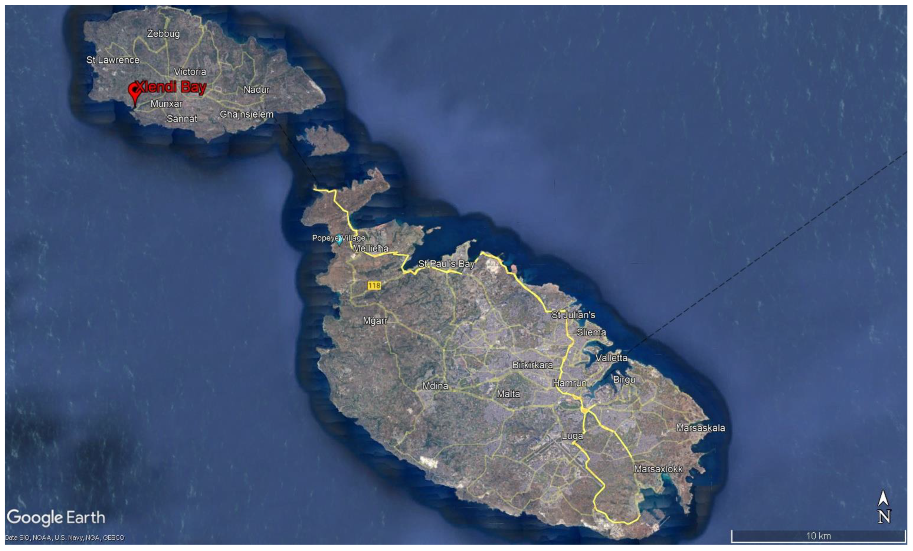
8] (p. 89). Therefore, the availability of the necessary hardware and software to carry out photogrammetric documentation and the technological developments in both marine robotics and mixed gas CCR diving have made possible the excavation and documentation of underwater cultural heritage sites that were previously out of reach. This paper aims to expound upon how photogrammetric applications have been used to record the excavation of a deep water site, located at a depth of 110 m. The project in discussion is the Phoenician Shipwreck Project, which saw the first ever excavation by divers beyond a depth of 100 m on an archaic shipwreck located off the coast of Xlendi Bay, Gozo, Malta (
Figure 1). The paper will present the workflow utilised to record the diver-led excavation, exemplifying how photogrammetric documentation can be used to accurately document an excavation that is severely limited by the amount of time divers are able to spend on the bottom.
2. The Archaeological Background
The location of the Maltese Islands in the centre of the Central Mediterranean has led to an inextricable connection between the human story of Malta and the sea, a connection that has left its mark on not only the landscape of the islands, but also on the surrounding seabed. For over two decades, the University of Malta and the Superintendence of Cultural Heritage (SCH) have been conducting offshore remote sensing surveys with the express aim of mapping the territorial seabed of the Maltese Islands and discovering the tangible expression of that connection [
9]. In 2007, a survey off the southwestern coast of Gozo revealed an anomaly on the seabed approximately 2 km from the entrance to Xlendi Bay and at a depth of 110 m (
Figure 2). The recorded anomaly hinted at the presence of a potential ancient shipwreck based on the general morphology of the target and its prominence on and dissimilarity to the otherwise sandy and sterile surrounding seabed [
10]. From a seafaring perspective, this area is considered hazardous. The curved topography of the surrounding cliffs, rising from the sea to stand over 160 m in height, the dramatic variations in depths, and the exposure to the prevailing north-westerly winds have all contributed to a confused sea-state [
11]. Xlendi Bay is today considered to be a small harbour for fishing and recreational vessels, but in antiquity, the inner harbour would have stretched a further 200 m inland, offering better refuge conditions [
12]. Additionally, Xlendi would have been the first haven available to vessels travelling from Carthage and Pantelleria [
11]. This potential for treacherous sea conditions and the proximity to Xlendi Bay contribute to the archaeological potential of the seabed in this area.
The significant potential of the anomaly discovered in 2007 resulted in a decision to carry out a second high-resolution survey where the sonar was flown 2 m above the seabed, and the resulting imagery allowed for the differentiation between rounded and rectangular objects, as well as what seems to be an area of disturbance through the centre of the site (
Figure 3) [
10].
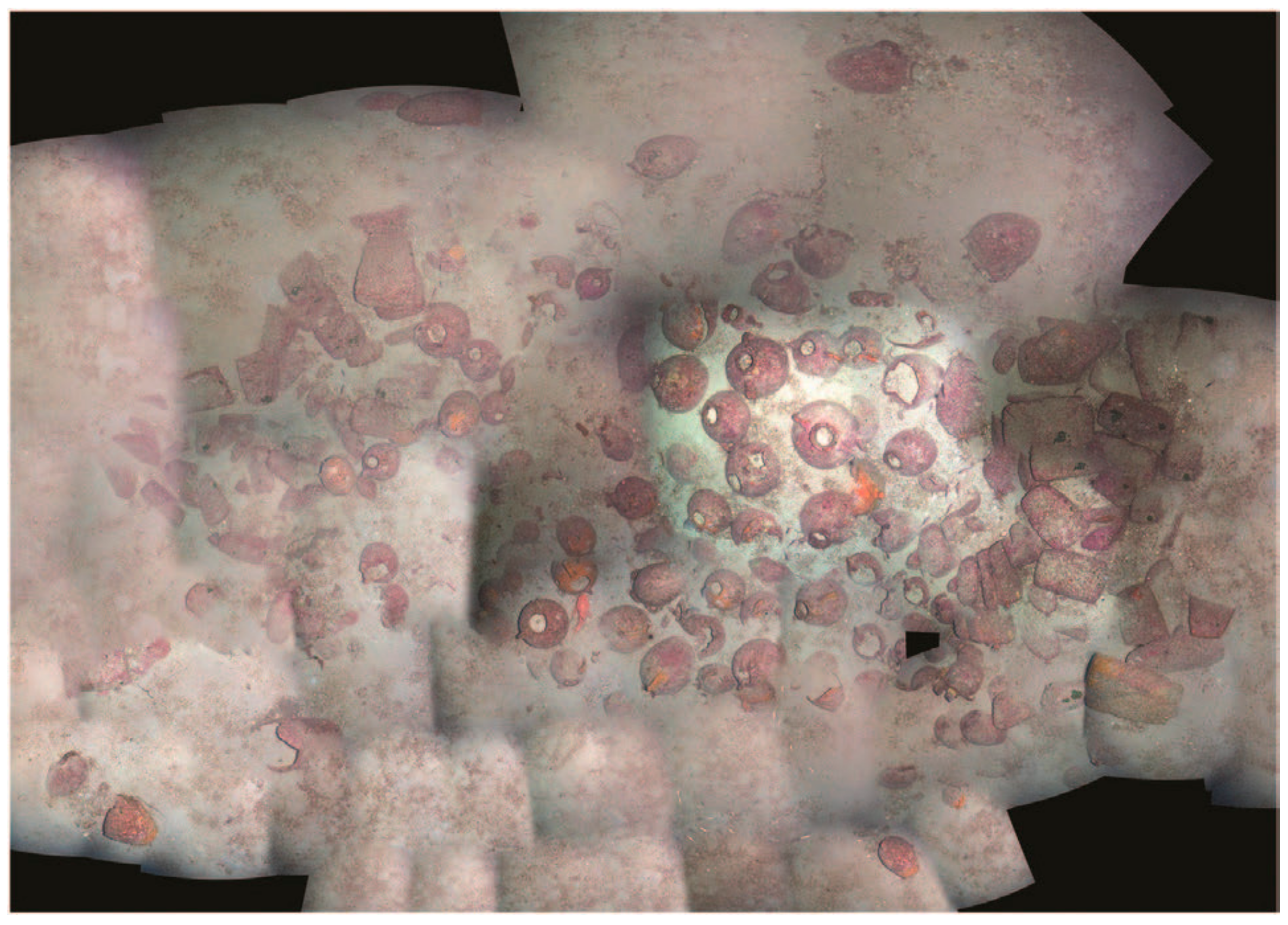
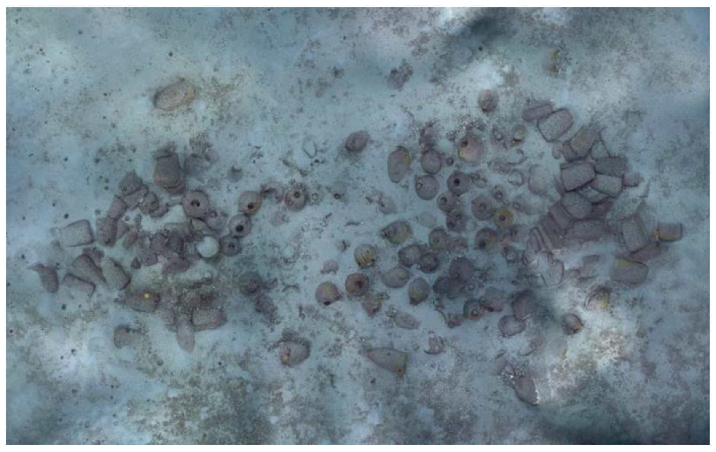
A sub-bottom profile survey carried out a year later revealed the presence of buried material, which enabled the planning of ROV surveys in 2009 that conclusively defined the nature of the anomaly. The resulting survey gathered several minutes of video footage and general photographs that “permitted the final confirmation that the anomaly was indeed an ancient shipwreck” [
10] (p. 75). The presence of mixed cargo consisting of amphorae and saddle querns that correspond to the rounded and rectangular objects first revealed in the high-frequency sonar survey were datable to the 7th century BC. This confirmed the site as an archaic wreck, and to date, it is the oldest known shipwreck in the central Mediterranean. The ROV-captured photographs were used to create a photomosaic of the site, but a consistent lack of vessel stability on the surface meant that the lines of the ROV were executed manually. Whilst the resulting quality was not of scientific standard, it was suitable for planning purposes and allowed researchers to see the site in its entirety (
Figure 4) [
10].
2014–2017 Seasons
Further work on the site was stalled until 2014, when a grant application was accepted that resulted in the use of the Minibex, a 30-m vessel with dynamic positioning that allowed for the reliable deployment of a two-person submersible, the Remora 2000. The submersible was set up for photogrammetry with the goals of carrying out a high-resolution survey, but to also recover selected objects and to allow archaeologists the opportunity to closely inspect the site, usually made difficult if not impossible by the 110-metre water column separating the surface from the seabed [
10] (
Figure 5).
The precise setup of the submersible in terms of camera and light equipment, and how this impacted the 3D survey can be found in Drap et al., 2015 [
13]. The selection of objects for recovery was based on how representative of the entire cargo they were and how easy and non-invasive recovery would be. A total of four objects were raised—a saddle quern base, an ovoid amphora, a flat-bottomed amphora, and an urn. The success of the 2014 field season led to further funding being allocated for 2016–2017 [
10]. This time, a vessel with dynamic positioning and a submersible was not available, and a decision was made to deploy divers to carry out surveys and recover objects. Objects chosen for recovery in the 2016–2017 seasons included typologies not recovered in 2014, typologies like those previously recovered for comparative reasons, a rubbing stone, and fragments that were clearly in secondary positions. A total of 17 objects were recovered up until this stage of the project [
14]. An analysis of the visible elements of the wreck allowed the cargo to be split into three main sections—the two extremities of the site composed of a visible 66 saddle querns and rubbing stones, and the central part of the site consisting of a visible 99 ceramic containers. An analysis of the cargo present is discussed in Gambin et al., 2021 [
14].
3. Excavation 2018–2021
The 2001 UNESCO Convention on the Protection of the Underwater Cultural Heritage was set up to “ensure the effective protection of underwater cultural heritage and its preservation for future generations” [
15] (p. 13). To this effect, in situ preservation is presented as the preferred option, with exceptions for objects and sites that may make “a significant contribution to the protection of or knowledge about underwater cultural heritage” [
15] (p. 13). Various archaeological handbooks stress the importance of non-invasive methods, relying on survey and recording techniques to gather as much information as possible [
16,
17]. This relates to the fact that archaeological excavation is inherently destructive, with objects and sediments removed to reveal what is beneath them. The destructive nature of the process of excavation warrants the question as to whether the significance of an object or site justifies the intervention. When discussed in relation to underwater remains, this question is usually asked more than once, since underwater projects are often more complex logistically and may carry a higher financial burden. This is particularly true when discussing deep water projects, where the associated risk is higher and more palpable.
Therefore, when it comes to underwater cultural heritage, preservation in situ is often also the preferred approach from an economic perspective, and intrusive techniques are only justifiable when a site is under threat or when visual surveys have reached the limit of what is discernible. These variables are often coupled with the rarity or uniqueness of a site, and excavation is planned only if all these elements align [
15,
16,
17]. In the case of the Phoenician shipwreck, the sparsity of similar sites in the Mediterranean provided a legitimate foundation for the planning of an archaeological excavation. The initial fieldwork seasons provided a solid foundation on which an excavation could be planned, and the analysis of the visible elements of the cargo and the sub-bottom profile data all hinted at the potential of significant material and information being buried beneath the main cargo. Based on this, a decision was taken to conduct an excavation using specialised technical divers, and between 2018 and 2021, the first scientific excavation at a depth of 110 m was successfully concluded.
Planning the excavation of an underwater site is often more of a challenge than it is on land, owing to the specific diving skills required and the equipment and logistics involved. Divers on this project used mixed gas CCR with a trimix consisting of 8% oxygen, 72% helium, and trace gases making up the remainder. Dives to such depths are challenging endeavours, one of which is the strict limitation of time. It takes divers approximately six minutes to descend 110 m followed by no longer than 12 min on the site itself. It subsequently takes over two hours for divers to complete their decompression obligations as they return to the surface. This time limitation moulded many approaches that needed to be developed to excavate this shipwreck [
10]. Moreover, several tools were modified to facilitate the process of underwater excavation at depth. For example, regarding the water dredges, the surface pump was replaced with a hydraulics-powered submersible pump. A hydraulic machine was housed on the bow of the dive vessel, with one team member always responsible for its operation. Hydraulic hoses were lowered and secured along the shot line with the submersible pump positioned at 95 m. Supply hoses were connected the pumps to two dredges with long discharge pipes. The dredges were placed close to the trenches, and the discharge pipes initially emptied into two bags, which were later sieved and screened on the surface. Excavations were carried out in teams of three, with two divers operating the dredges and one acting as safety. The diver’s hand is the most important tool when it comes to underwater excavation, and hand-fanning techniques were also used in Xlendi, carefully and systematically removing sediment. Ceramics and other archaeological material were placed in labelled mesh bags and recovered at the end of the dive.
One dive, either the first or the last depending on various circumstances and specific objectives, revolved around recording the excavation trench as left by the last dive team during prior excavation or recovery activity. Recording of the excavation progress is needed to provide an objective and accurate account of the excavation, and the choice of recording system is an important consideration. Traditional recording methods utilise tapes, rulers, spirit levels, and plumb bobs, even underwater. As discussed previously, this is a time-consuming exercise that is also impacted by elements such as current and visibility. At a depth of 110 m, this is not a safe or feasible option, with divers limited to 12 min on the site. Consideration was also made of the fact that traditional recording methods would not be sufficiently accurate enough to record the often-small changes to the site that a typical day’s excavation would achieve. This meant that an alternative recording methodology had to be implemented. The recording of deep-water archaeological sites is usually a remote activity involving large surface vessels with dynamic positioning, ROVs, and significant funds [
5]. Today, small-to-medium sized ROVs that can be deployed from any vessel are becoming more affordable and are common sights on underwater archaeological projects. In fact, a Gladius mini ROV rated to 100 m was often deployed in the first excavation seasons; however, the purpose of the Gladius was to provide an additional level of safety, with surface support team members able to maintain a visual on divers excavating below. The ROV was not used to gather 3D data. The advantage of direct human interaction with a site and the ability be flexible and adjust parameters as necessary affords a level of decision-making that is “to-date, sharper than those obtainable through the sole use of robotics” [
10] (p. 84). Additionally, despite the new approaches to recording deep sites developed by Drap et al., 2015 [
13] and Drap et al., 2018 [
10] in the context of this shipwreck, simpler, low-cost, and diver-led photogrammetric documentation was necessary.
The following section will focus on the recording method used in the excavation of the Phoenician shipwreck conceived and executed.
4. Recording Methodology
The process of 3D documentation followed a specific workflow, whereby prior to any excavation or recovery activity, data was captured to create a baseline model. Any activity following this was then recorded anew. These new models can be referred to as “child models” and usually only covered the quadrants being excavated rather than the whole shipwreck site. This system allowed for excavation to be recorded to millimetric accuracy, with 3D models generated and excavation levels recorded for every 50 min of excavation. Quantification is based on four teams of divers excavating for 12 min per team in one diving day. It is safe to state that the frequency of recording is, at the very least, equal to what is practiced during terrestrial excavations.
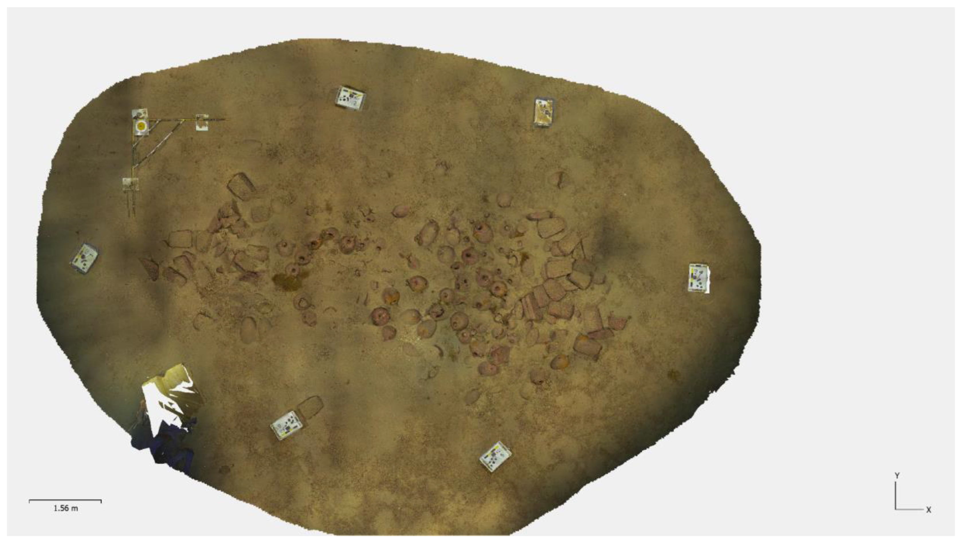
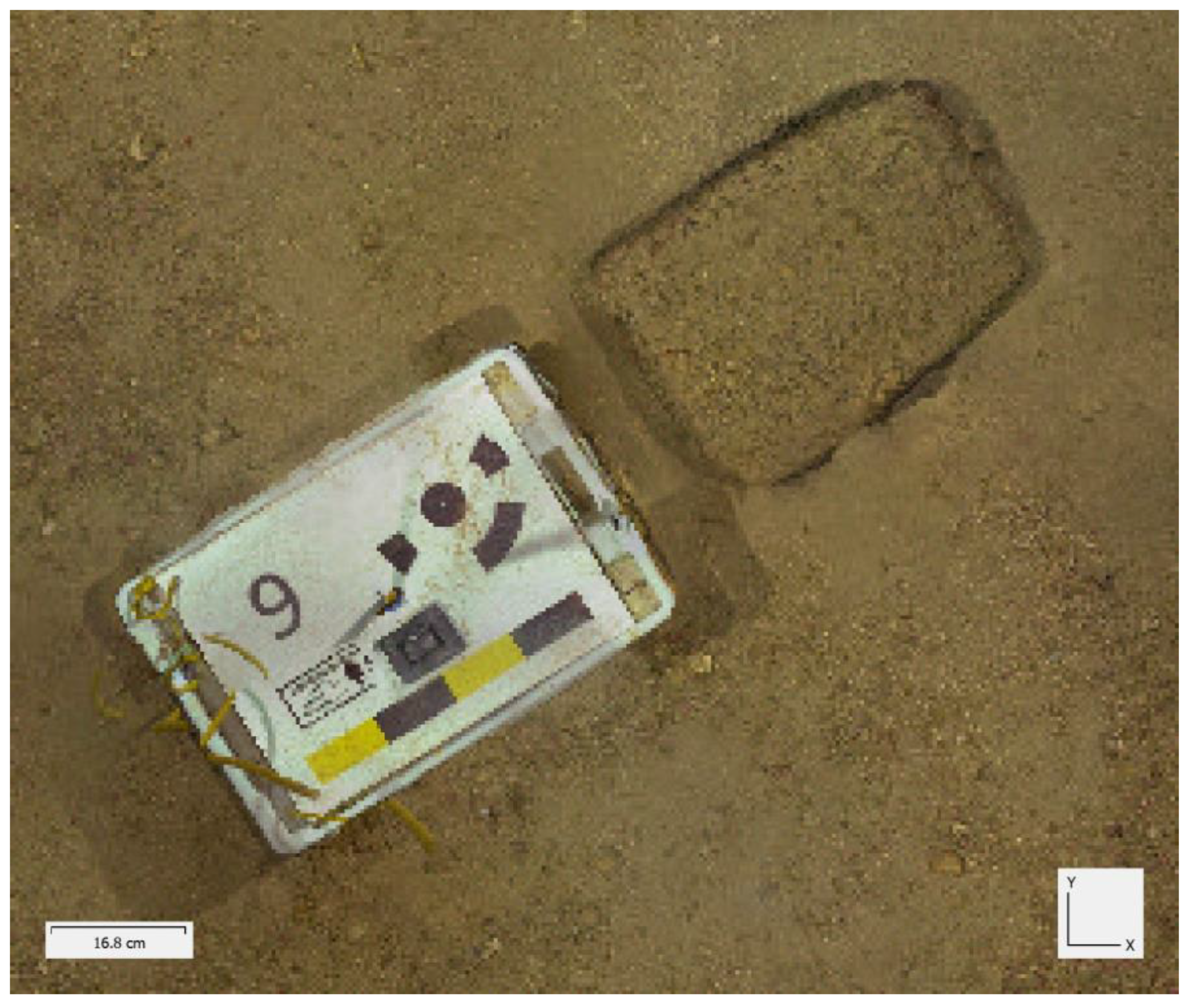
Before any excavation or excavation-led documentation could be undertaken, control points had to be established that would serve as a local coordinate system throughout the duration of the project. Specially cast concrete blocks, measuring approximately 60 cm × 40 cm × 30 cm, acted as platforms for coded targets, with each block containing a unique combination of three coded targets of varying sizes to ensure automatic recognition by the processing software—Agisoft Metashape 1.8.5—irrespective of image resolution or the distance from target. The attachment of the coded targets to the concrete blocks diminished any potential movement issues encountered during fieldwork. The movement of blocks, no matter how slight, will introduce unwanted errors. To mitigate this potential scenario, a total of six target blocks were placed around the site to provide redundancy and allow a continuous adaptation of the local coordinates as work progressed (
Figure 6). Actions that can lead to the movement of control target blocks include diver action as well as any excavation equipment, such as hoses and dredges. Targets were securely affixed to the blocks using cable ties. Moreover, the coded targets were fabricated from negatively buoyant materials to prevent displacement. Such measures ensured consistent alignment and measurements across the subsequent models. The six control points and several scale bars were strategically positioned around the shipwreck. The scale bars were made of plastic trunking, and provided additional control checks for the main scaling system for which the coded targets were designed. Whilst the concrete target blocks were left in situ, the scales were removed. Prior to commencing the excavation, the blocks and scales were measured, plotted, and utilized to construct the baseline model, which served as the comparative reference for all subsequent 3D models.
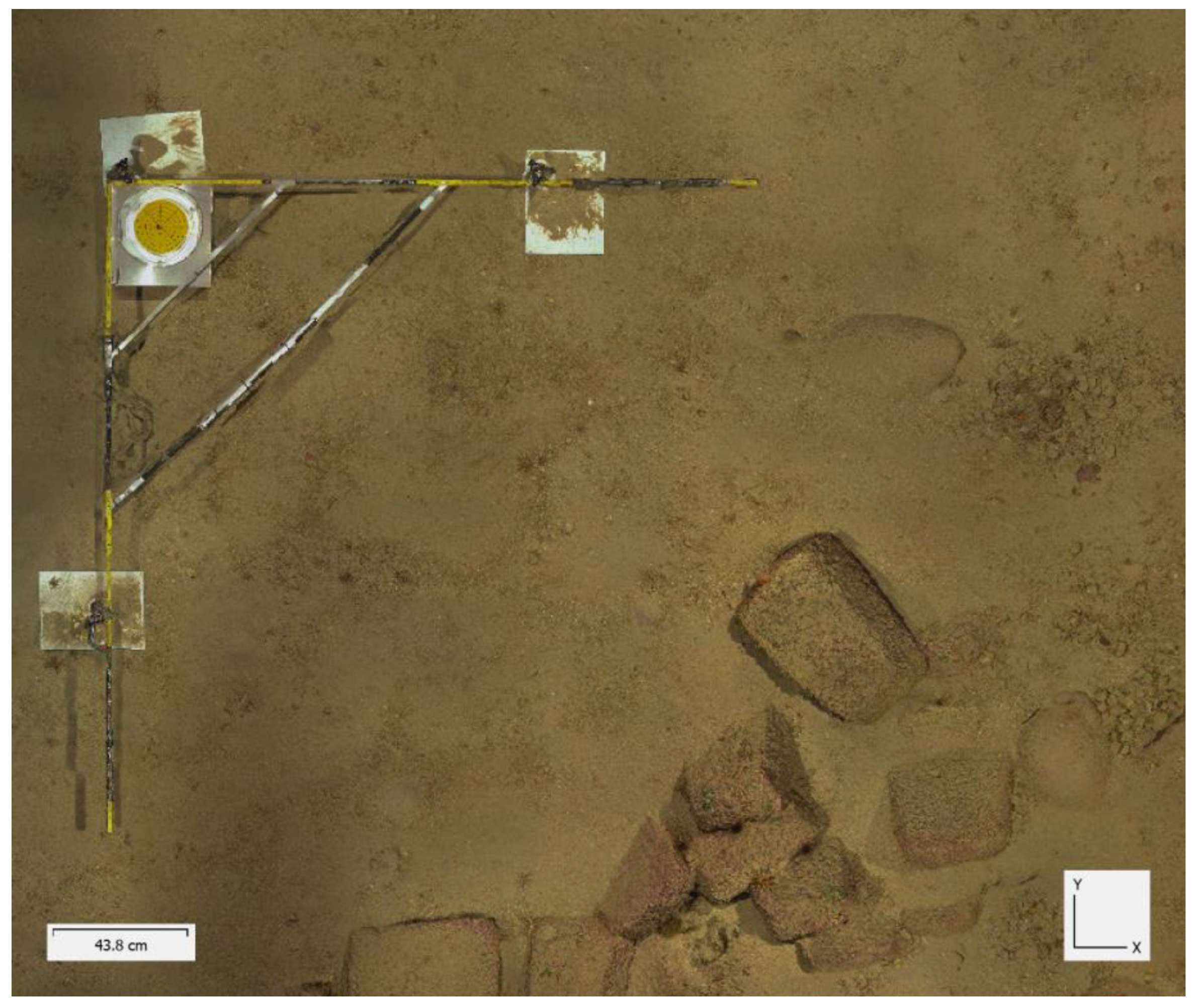
In addition, to accurately capture the inclination of the plane from a
Z-axis perspective, a 2 m by 2 m reference measuring square was carefully positioned in a perfectly horizontal manner at the excavation site. This was achieved using a bullseye level and adjustable legs placed on ceramic tiles to ensure stability (
Figure 7). This scale provided a set of marked reference local coordinates ({0,0,0/0,2000,0/2000,0,0}) to facilitate precise measurements of the plane’s inclination during data capture. Once the local coordinate system was established with reference to the six control points, the level square was no longer required, and removed. However, the scale bars were retained to serve as control measurements for the models.
Data capture for the project was based on a photogrammetry set up that consists of a Sony A7III mirrorless full-frame camera (Sony, Tokyo, Japan), a suitable wide-angle lens, and an arrangement of powerful underwater video lights, providing up to 70,000 lumens. The camera was set to a shutter speed of 1/200 s, aperture at f8, and ISO and white balance set to Auto. A small video camera, a GoPro, was set to record video whilst the main camera captured stills. This acted as an extra tool to aid in image alignment, particularly if a lack of overlap was noted in the stills. The video camera also acted as a secondary recording device in case of a primary camera malfunction.
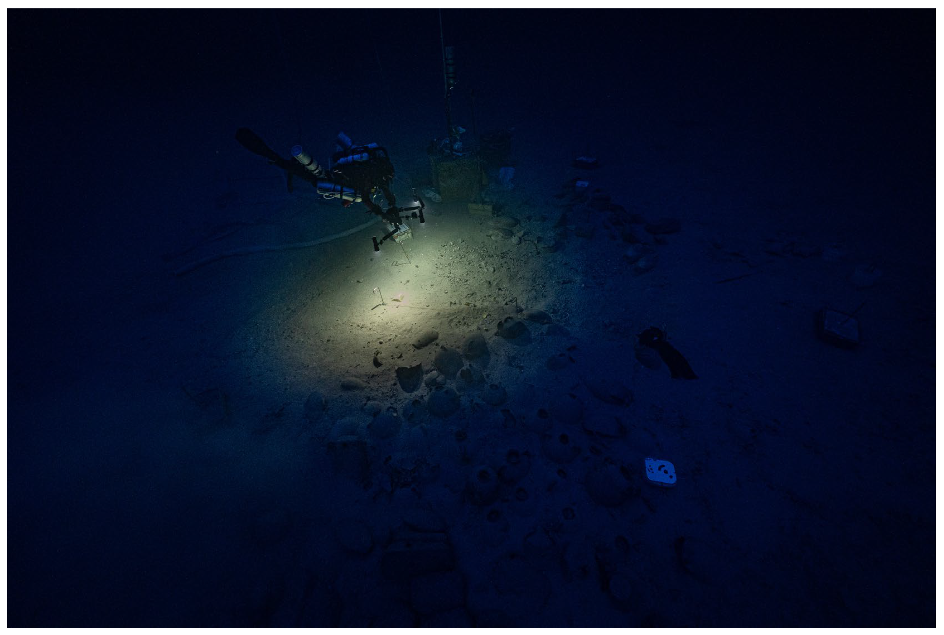
At the start of a season, and prior to starting excavation activities, a baseline model of the complete site was recorded. This permitted the detection of any changes that may have occurred on the site over the winter period. Such changes could be natural, induced by currents or marine activity. Alternatively, the site may also have been disturbed by illegal fishing. Throughout the four-season excavation, no anthropogenic impacts were noted. The annual baseline model served to execute adjustments to recording techniques if necessary. For the first season, the level square technique described above was used to create the local coordinate system. At the start of subsequent seasons, specific feature points from the shipwreck itself were selected and matched to the baseline model of the previous season. Additionally, no equipment was lowered to the site prior to the data acquisition for the first model of the new season, ensuring that dredges, pipes, crates, and other hardware did not clutter the baseline model. To facilitate automatic detection of the targets by the software, the recording team ensured that the coded targets were cleared of any sediment that may have settled on them before commencing data acquisition. For the data capture phase, divers meticulously adhered to the recommended fly path, employing a slow finning cadence while maintaining a downward-facing camera orientation to ensure that images are captured in a vertical manner. Divers maintained a height of between 1 m to 2 m from the seabed (
Figure 8). Therefore, with careful planning, divers were able to gather high-quality data with sufficient overlap, and through an established familiarity with the site and its features, were able maintain their swim path and height.
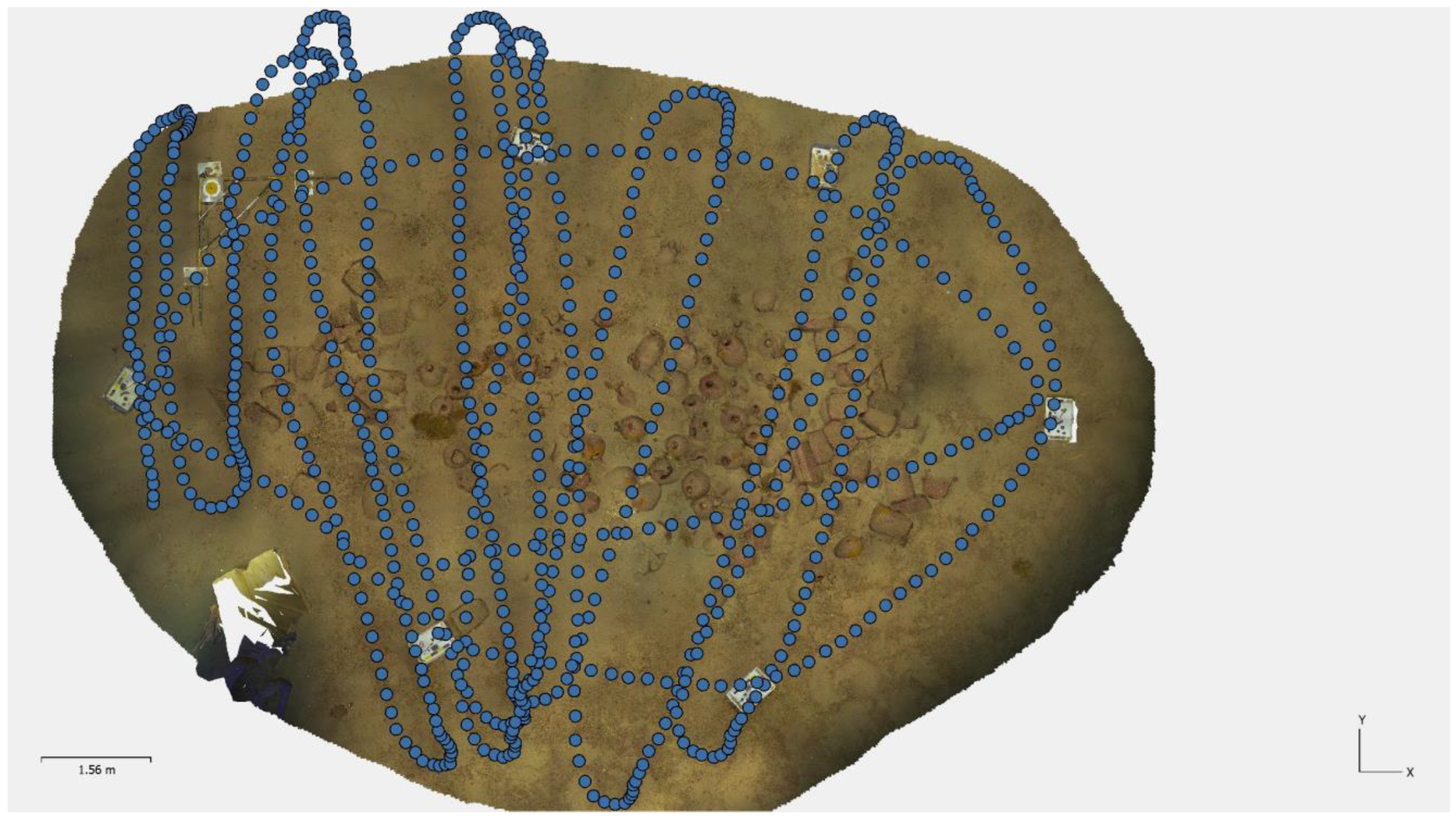
A typical scan of the entire site is composed of approximately 2500 photographs, including a ‘boundary’ of the site which ensures coverage of the six control targets (
Figure 9). Due to the limited time on site, two separate dives were required to capture data for the complete site. The flypath for the complete site was carried out in two parts. The first path traversed the complete perimeter of the site, using the coded targets as the visual reference points. The second part involved running transects across the width of the site, again using the coded blocks as visual markers. Full coverage was ensured by allowing for a sufficient buffer for parallel tracks to overlap, relying mainly on the experience of the individuals gathering the data to travel at a relatively consistent distance from the seabed to achieve the required overlap. In respect to the complete site, most images were captured at a nadiral orientation to the site; however, the camera operator also used angled orientation to increase the robustness of the data. Some vertical data was also captured due to the wide-angle lens (12–14 mm) that was typically used. This allowed for substantial non-horizontal data to also be captured. When it came to the daily recording of the excavation trench, an angled orientation was included to capture the sections of the trench. During the final season in 2021, scooter-mounted cameras were deployed, thus permitting data capture to be completed in a single dive. The scooters were run at approximately 30 m per min or 0.5 m per second, and images were captured at an interval of 0.8 s, at a height of 1.5 m to 2.5 m off the seabed. This was calculated to provide substantially more than the required overlap of 80%, allowing for a sufficient margin of error in the case of faster or closer runs than planned.
Processing of Data
The processing of baseline data involved a series of steps, outlined below:
RAW images are loaded into Lightroom (LR), where white balance correction and any necessary adjustments for exposure and contrast are applied.
Edited images are then exported as JPEG files with the original size and loaded into Agisoft Metashape.
Automatic detection of the coded targets takes place using Metashape
Photos are aligned, and the correctness of the alignment verified in Metashape.
Scale bars are manually created in Metashape using the physical scale bars generated in the model as a basis. Metashape allows the placement of markers onto images. Therefore, any two markers can be defined as a scalebar, and a physical measurement applied to that scalebar.
Establishment of the coordinate system (using the level square method for the first season and the feature method for subsequent seasons).
Creation of mesh and subsequent texturing.
Export of a text file with estimated coordinates for the coded targets for use with future ‘child’ model imports. (
Figure 10).
Changes after excavation were recorded in “child models”. Only the excavation trench was documented for these daily models. The fly path over the trench included a ‘boundary’ outside of the four by two metre area. It also included at least three of the six control points. A workflow similar to the baseline processing methodology was applied. A minimum of three control points were used to align the “child” model with the baseline model (
Figure 11).
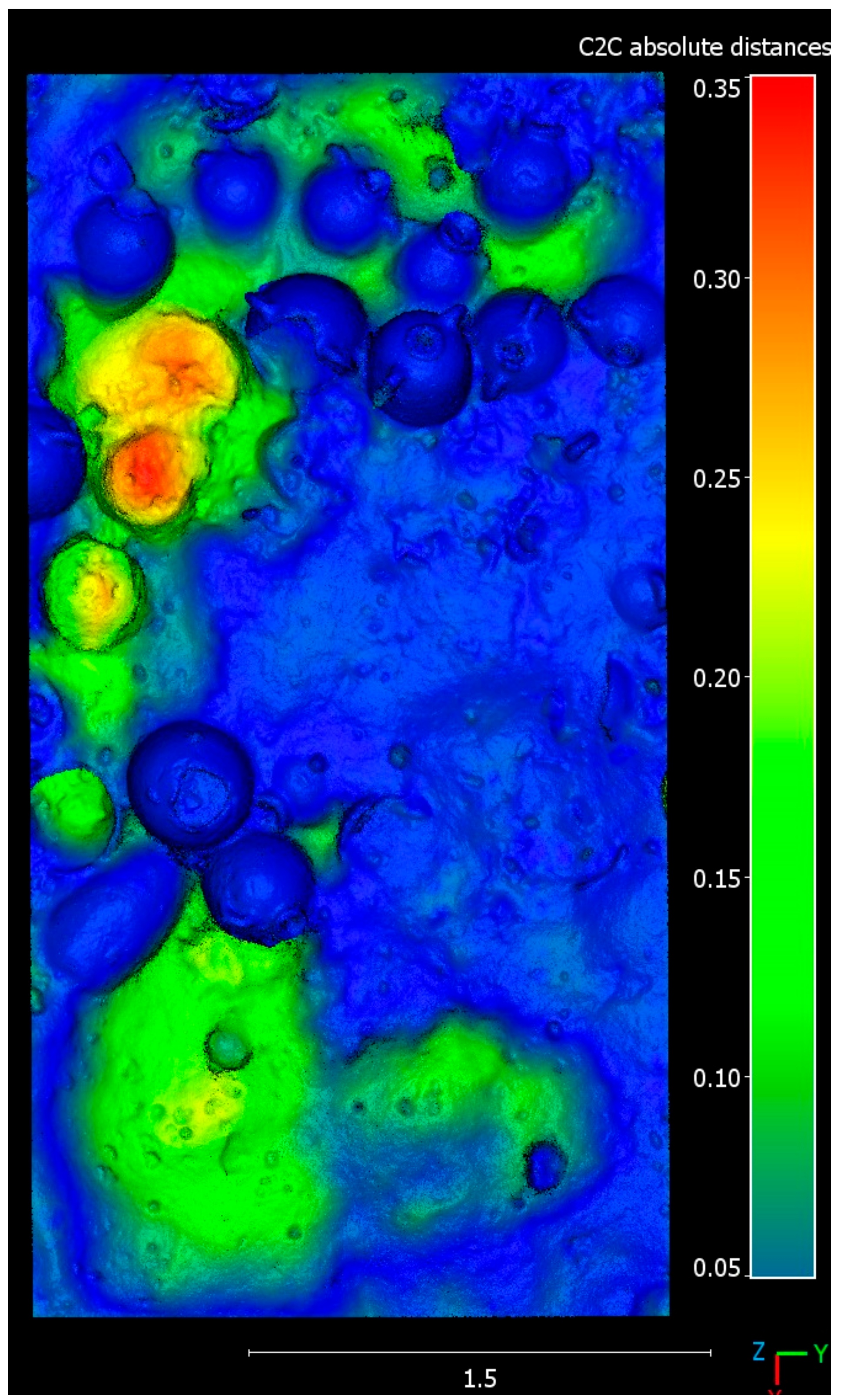
The coded targets making up the control points are detected by Metashape. Targets that are not detected are assigned manual marker placements and their coordinates marked in the form of <x, y, z> imported from the baseline (or adjusted baseline) coordinates into the new model. This permits the ‘import’ of scaling and positioning data into the daily models. It thus becomes possible to accurately overlay different models. The cloud-to-cloud processing function of CloudCompare 1.12.4 is subsequently used to produce a daily render with the DEM transformation function in Metashape, and it was also used in subsequent excavation seasons. Cloud-to-cloud processing produces the variance in excavation depths from one day to the next. Differences in levels are presented through a colour scale (
Figure 12).
6. Conclusions
The 3D recording and processing methodologies described in the article offer significant advantages for archaeological excavations underwater. Solutions presented expedite the process and facilitate deep water excavations by doing away with traditional recording methods, which are too cumbersome and time consuming when divers are on a site for just 14 min. These approaches leverage advanced imaging and data processing techniques to overcome the challenges encountered in deep underwater environments. Moreover, local coordinate systems developed specifically for this project provide detailed and accurate data for underwater archaeological sites, including excavation levels, 3D models, scaled orthophotos, as well as thousands of high-resolution images that can be used to verify details and characteristics of the archaeological objects and layers. Moreover, by capturing precise 3D representations, researchers can effectively plan and execute excavations with greater efficiency. Planning and execution were also greatly aided by PoV cameras, a simple yet effective means for archaeologists to observe the work of fellow divers. Additionally, the article highlights the development of data processing flows that are relatively simple and yet very robust. This workflow enabled the team of researchers to analyse and interpret the large datasets collected from the Phoenician shipwreck. By leveraging advanced computational techniques, models and excavation levels were produced within hours of the dive’s end. This enabled the team to rapidly identify where and how excavation should proceed, thus facilitating informed decisions about excavation strategies. It also provided data for the analysis of artefacts in their respective contexts. Overall, the underwater recording approach and post-dive processing were streamlined. Additionally, the integration of 3D recording and processing methodologies offers the advantage of remote access and analysis. Researchers can remotely access and analyse the recorded 3D data, reducing the need for a physical presence at the excavation site. This capability is particularly valuable in deep water excavations, where direct human observation is currently limited to those qualified for deep technical diving. By remotely accessing the 3D data, researchers can explore submerged sites and contribute to a better understanding of this particularly important shipwreck.

