1. Introduction
In recent years, underwater acoustic networks (UANs), as a momentous extension of Internet-of-Things technology to the underwater environment, have captured growing attention in academia and industry because of their wide range of use, for example, ocean monitoring, oceanographic data collection, disaster warning, diving, and so on. In order to enable various underwater nodes with diverse missions to be networked in a flexible manner to meet those applications, a UAN with the WiFi network architecture, called UW-WiFi, is presented in [
1], similarly to the traditional terrestrial WiFi network, which provides wireless access services for underwater nodes (e.g., marine engineering equipment, automatic underwater vehicles, divers, sensors, and so on). The UW-WiFi network affords distinct types of data collecting activities in uplinks, command control actions in downlinks and interacting functions between any two nodes.
To accomplish the UW-WiFi network consisting of heterogeneous nodes, designing a practical medium access control (MAC) protocol is indispensable. Nevertheless, MAC protocols, mainly including carrier sense multiple access (CSMA), time division multiple access (TDMA), frequency division multiple access (FDMA), and code division multiple access (CDMA), designed for the terrestrial WiFi network [
2] are not applicable for the UW-WiFi network, due to typical characteristics of the underwater acoustic channel, such as low available bandwidth, long and variable propagation delay, high bit error rate, and time-varying. The underwater acoustic speed is approximately 1500 m/s, five orders of magnitude lower than the optical speed (
m/s), which makes CSMA based on the Request To Send/Clear To Send (RTS/CTS) exchanging costly. Because of the narrow available bandwidth, FDMA is impractical. TDMA requires precise time synchronization, which is difficult and needs extra cost to achieve. The near-far effect is usually difficult to be eradicated in the time-varying acoustic channel, leading CDMA to be not suitable for the UW-WiFi network. Several related works have been proposed for underwater data collection networks [
3,
4,
5]. A customized Slotted-FAMA protocol is introduced for underwater acoustic WiFi networks [
3]. This protocol only caters for applicable scenarios with low node density and traffic load, in which as the data traffic increases, the conflict of control packets will become sharply harsh. Two MAC protocols based on TDMA, namely, Transmit Delay Allocation MAC (TDA-MAC) and Accelerated TDA-MAC, are proposed [
4], which have no need for clock synchronization. However, the algorithm is quite inflexible and unable to adapt to the various data volume requirements of nodes. A deep reinforcement learning-based MAC protocol is proposed [
5], which is highly complex, and has high requirements for hardware computing and energy consumption, which makes it hard to be applicable in real situations. Furthermore, the hardship and high-cost of setting up real underwater network systems and executing field experiments lead to most research being based on theoretical analysis and simulations. However, dynamic underwater acoustic channel and complicated communication systems cannot be well reflected by simulation.
Given the above issues, and considering the limitations of underwater acoustic communication channel, energy conservation, the different needs of heterogeneous nodes for the shared channel and the usability of the algorithm, a time sequence-based dynamic on-demand assignment (SDDA) MAC protocol is proposed and implemented in an actual system for the UW-WiFi network. By combining the main point of TDMA and reservation, this protocol improves channel utilization and packet delivery ratio, decreases end-to-end delay, and achieves good fairness among terminal nodes at different ranges. This protocol mainly includes two phases, the reservation phase and the time sequence scheduling phase. To avoid collisions of request packets during the reservation phase, the sending time of request packets from each terminal node is calculated by exploiting propagation delays. During the time sequence scheduling phase, the timing of every node beginning to transmit data is figured out according to the data transmission delay and the propagation delay from itself to the master node. This on-demand scheduling algorithm does not require time synchronization and saves energy by reducing the number of control packets and preventing all packets from conflicting. Overall, the key contributions of our work are summarized as follows:
Based on the UW-WiFi network scenario that addresses real-world application issues, and taking the above various constraints into account, a practical MAC protocol is proposed, which can allocate channel resources on demand according to the different data sizes of each node under diverse duties.
To thoroughly verify the practicability of the SDDA MAC protocol, we have performed numerous simulations and two types of ocean trials. The comparison simulation experimental results show that the SDDA protocol substantially outperforms TDMA and S-FAMA [
6] on channel utilization, packet delivery ratio, and end-to-end delay. Then, we implement the SDDA protocol in the embedded motherboard and build a real UW-WiFi network system at Daya bay, Shenzhen. The first type of tests is mainly to validate the effectiveness of the simulation, and it is obtained that the sea test results conform to the simulation. The other type is the experiments on different tasks of nodes, from which we collect the distinct real ocean data, which demonstrate the utility of the proposed protocol. The sea trials also show that the SDDA is a feasible solution for the real UW-WiFi network deployments.
The remainder of this paper is organized as following.
Section 2 gives a brief overview of the state of art on the related protocols.
Section 3 discusses the application scenario.
Section 4 gives a detailed description of the proposed SDDA MAC protocol.
Section 5 presents extensive simulations and sea trials to testify the performance of the SDDA protocol. Finally,
Section 6 concludes the paper.
2. Related Work
There has been extensive research on MAC protocols for UANs. These work can be classified into three categories: contention-free, contention-based, and hybrid, which this section will examine in the UW-WiFi network scenario.
Contention-free MAC protocols, mainly including TDMA, FDMA, CDMA, and their variants, allocate network resources to specific nodes but not on-demand. TDMA divides the channel into multiple time slots and assigns each time slot to each node [
7], in which, data are buffered by a node before being transmitted until its assigned time slot. Each node can take full advantage of the available bandwidth during its time slot. Unfortunately, TDMA requires strict time synchronization amongst all of the nodes in the network. Additionally, when network nodes have no data to send, their time slots are wasted. FDMA divides the available frequency band into multiple sub-bands and assigns a sub-band to each user [
8], by which it guarantees collisions free among nodes. This algorithm is simple and efficient when dealing with a small number of nodes in uniformly constant traffic. However, for networks with changes in scale and traffic, such as UANs, it is unadjustable and inefficient. Additionally, guard bands are needed between sub-bands to compensate for imperfect filters, adjacent channel interference, and spectral spreading due to the Doppler Effect, which decreases the available bandwidth. CDMA allocates a unique code to each node, allowing multiple nodes to transmit packets concurrently by using the entire bandwidth. However, to prevent the near-far effect, it needs a power control algorithm to adjust the appropriate output power level for each node [
9], which is hard to accomplish in actual sea applications.
Contention-based protocols are clustered into random access and handshaking based. The random access approaches majorly comprise ALOHA, CSMA, and their variants, which are suitable for UANs with lower data traffic and sparser deployment. In the original Aloha protocol, Whenever a node has information to send, it transmits the information immediately, which cannot avoid collisions and will result in a high probability of retransmission and ultimately reduce the network performance. Due to a number of retransmissions, the maximum achievable throughput of the original Aloha protocol is only
[
10,
11]. Roberts et al. proposed Aloha with Collision Avoidance (Aloha-CA) and Aloha with Advance Notification (Aloha-AN) to reduce collisions [
12], both of which utilize overhearing messages and propagation delays between nodes to avoid collisions. However, when the number of nodes and network traffic increase, the collision may increase as well. CSMA protocol avoids collisions by requiring a node to sense the channel prior to data transmission [
13], which only addresses the sender-side collisions, while the receiver is still vulnerable to collisions due to the hidden terminal problem [
14]. Details and various designs of CSMA can be found in [
15,
16,
17]. The handshaking-based protocols employ RTS/CTS control packet exchanges to reduce data packet conflicts. Molins proposes a protocol named S-FAMA [
6] which uses a four-way handshaking with time-slotting to avoid data collisions. To reduce reservation duration, the DACAP protocol allows a node to use different handshaking lengths for different receivers [
18]. SASHA [
19] is a hybrid approach of selective automatic repeat request (ARQ) and slotted handshaking access, in which after each successful negotiation, the sender pushes multiple available packets into a train to reduce the average overhead and improve the channel utilization. A multiple access with collision avoidance MAC protocol named fixed interval MACA (FI-MACA) [
20] is proposed, where the sender can detect collisions effectively with low complexity, and the receiver also listens to the channel for a while to solve the hidden station problem before responding a CTS to the sender. However, because of the long preamble of acoustic modems [
21] and the long propagation delay in the underwater acoustic channel, when the network load is heavy, the pure handshaking-based solution will spend a lot of time on channel reservation.
Different from the abovementioned protocols, hybrid protocols make use of the positive characteristics of both contention-free and contention-based. Zilong Liao et al. [
22] propose a handshake-based ordered scheduling MAC (HOSM) protocol for underwater acoustic local area networks, which utilizes a variant Max–Min Ant System algorithm to calculate the optimal order for each data transmission round to improve channel utilization while maintaining low delay and good spatial fairness. Two MAC protocols, namely, Transmit Delay Allocation MAC (TDA-MAC) and Accelerated TDA-MAC, are proposed to provide time division multiple access to sensor nodes without the need for centralized clock synchronization, and to utilize ping packets to calculate the propagation delays between nodes, achieving the ordered scheduling [
4]. J. H. et al. [
23] propose a sequence-scheduled and query-based MAC (SQ-MAC) protocol for UANs with a mobile node, which is receiver-initiated [
24], and can effectively avoid the sender–receiver collision [
25] caused by the long propagation delay. Additionally, in this protocol, the ant colony algorithm [
26] is adopted as Ref. [
22] to schedule the transmission order of data packets to improve channel utilization. However, to ensure the real-time of mobile node data as much as possible, it increases the delay of static node data. However, none of these protocols consider the different data requirements of different nodes in practical applications.
To some extent, the above protocols are capable of achieving their performance goals in the network model that they are concerned with and mainly based on theory analysis and simulation tests. Moreover, their performance is limited for UW-WiFi networks comprised of nodes with various task types. Accordingly, our work is significant for this kind of practical network scenario.
3. Application Scenario
Underwater Internet-of-Things (UIoT), as a significant extension of Internet of Things in underwater environments, is regarded as the network of interconnected underwater smart objects. UANs, considered as a promising network infrastructure to support UIoT, have wide application prospects in marine scientific investigation, ocean environment observation, marine ranch monitoring, disaster prevention, underwater rescue, coastal guard, military reconnaissance, blockades, etc. Usually, UANs, meeting the above application scenarios, are composed of heterogeneous nodes with heterogeneous data. For example, the nodes may include surface buoys, submerged buoys, unmanned underwater vehicles (UUV), gliders, unmanned surface vessels (USV), and so on; and the data may include sonar detection data, image, hydrological data, status data, command data, etc. Additionally, these UANs need to have the following functions: data acquisition in the uplink, remote command control in the downlink, and interaction between some nodes.
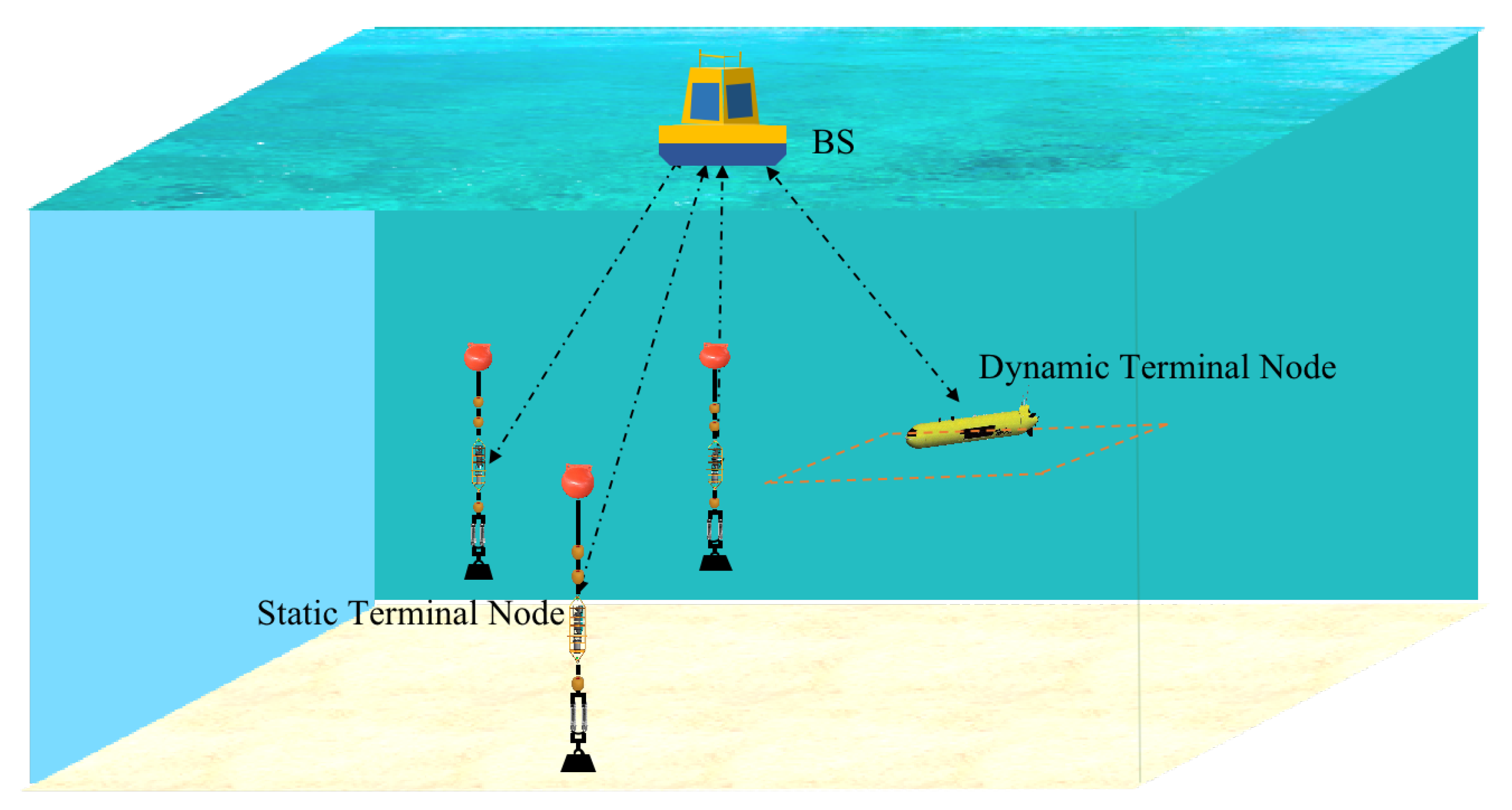
In view of the aforementioned actual requirements, and in order to enable flexible networking of heterogeneous nodes with diverse missions, the UW-WiFi network architecture is introduced, as shown in
Figure 1, in which the given UW-WiFi network is two-level, the first level consists of a surface gateway (called SG) and base stations (called BS) within SG’s communication range, and the second level is composed of multiple subnets consisting of base stations and terminal nodes within BS’s communication range. All terminal nodes in the whole network can be static or mobile. The radius of each subnet is the maximum communication range of the BS. Subnets are spatially far away from each other without interference between them. The BS of each subnet is responsible for providing wireless access services for terminal nodes, which can aggregate a wide variety of data from terminals and forward them to the SG through the upstream underwater acoustic link, and can relay commands from the SG or data from other nodes to its terminal nodes through the downstream underwater acoustic link. In this work, the designed MAC protocol is intended for each subnet, and the MAC protocol for the entire hierarchical UW-WiFi network, including a solution to switching among subnets for AUVs, is not in the scope of this paper, which will be our future work.
Designing a practical MAC protocol is of great significance to the UW-WiFi network. The MAC protocol is the basis for guaranteeing good quality of service in wireless networks. Taking into account the inherent characteristics of underwater acoustic signal with long propagation delay, low available bandwidth, and high bit error rate, as well as the diverse data transmission demand of nodes in the UW-WiFi network, the functional MAC scheme constructing is a challenging work. Firstly, in the case of different data transmitting needs of each terminal node in the network, how to effectively manage the access of multiple nodes to the shared channel to optimize the channel utilization. Secondly, how to resolve the issue that different types of data have different demands for reliability and real-time performance. In the following sections, we will discuss the MAC protocol design strategy.
4. Design of SDDA MAC Protocol
Overview of SDDA MAC Protocol
Firstly, we give an overview of SDDA, which performs on-demand scheduling and guarantees collision-free transmissions of both control packets and data packets. This protocol merged the reservation mechanism and the scheduling to fulfill a collision-free on-demand assignment. The most significant challenges for our collision-free scheduling are: (1) How to work out propagation delays from BS to all terminal nodes without time synchronization? (2) How to achieve the on-demand assignment for each node? (3) How to make sure collision-free transmissions of control packets from static and dynamic terminals? (4) How to ensure the reliability of data as far as possible in the case of packet loss caused by acoustic channel instability? Then we will show how SDDA solves these issues.
An example of packets transmission scheduling of SDDA MAC protocol is shown in
Figure 2. It can be seen from
Figure 2 that the processing flow is composed of three procedures: the initial reservation phase, the time sequence scheduling phase, and the data transmitting phase. In addition, there is a periodic regular reservation phase, described in the following. During the initial reservation phase, BS broadcasts a trigger (
) packet at first; and after receiving the
packet, those terminal nodes that have data to report send a request (
) packet to BS. Then, in the time sequence scheduling phase, after receiving all
packets, BS calculates the waiting time of each node before sending data packets on the basis of propagation delay and data transmission delay contained in the
packet and broadcasts a transmitting-start (
) packet, in which the scheduling information is embedded. Within the data transmitting phase, after receiving the
packet, those terminal nodes with data to send will start transmitting data packets at an appropriate time in the light of the scheduling information obtained from the
packet. Finally, at the end of data transmission, BS will broadcast an
and then, if any, forward data or command packets to the related terminals. Beyond those, it should be noted that the difference between the initial reservation phase and the periodic regular reservation phase is the method of handling
packet conflicts. Afterwards details about SDDA are as follows.
A. The Initial Reservation Phase. This phase mainly solves how to obtain the amount of data to be sent by each node and how to avoid the
packet collisions. During this phase, in the first place, BS records the current time (
) and broadcasts a
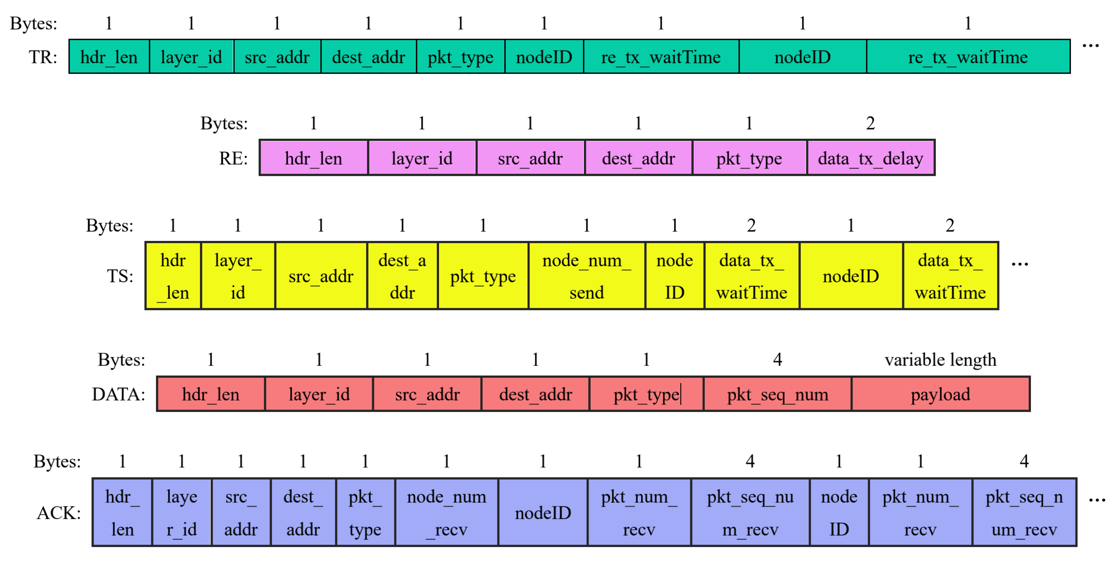
packet, the format of which is shown in
Figure 3 that reveals the meaning of each byte of
. For instance,
stands for the MAC layer ID,
means the length of header information of a MAC layer packet,
denotes the source address,
represents the destination address,
expresses the type of the present packet, and the rest (
and
) indicates the waiting time of each terminal node before transmitting an
packet. Actually,
is the waiting duration (
, where
i denotes the node ID) for each terminal node from receiving
to sending
. In the case where the propagation delays between each node and BS are not known at present, so as to prevent
packets from colliding, we adopt the maximum propagation delay (
) in the UW-WiFi network and the transmission delay of
packet (
) to compute the above-mentioned waiting duration. The computational formula is as follows:
After receiving
, each terminal node extracts its own waiting duration information from
in accordance with the node ID. Additionally, then they make use of the sum of the lengths of all data packets in the sending queue to figure out their respective data transmission delay (
) and put
(i.e.,
in the
packet shown in
Figure 3) into the
packet. When the waiting duration expires, terminal nodes dispatch
packets to BS. As long as BS receives an
, it takes notes on the reception time (
) and
carried in the
packet. Instead of plenty of RTS-CTS handshakes, this reservation scheme diminishes the number of control packets by broadcasting a
, while solving the problem of control packet collisions, hence saving energy, improving channel utilization, and shortening end-to-end delay. The pseudo code of this phase is shown in Algorithm 1.
| Algorithm 1. The Initial Reservation Phase. |
- 1.
for each node ID i, , n is the number of terminal nodes, do - 2.
calculate the transmitting time of each terminal node’s , - 3.
- 4.
end for - 5.
write each ’s transmitting time information into - 6.
record and broadcast - 7.
switch from the sending state to the waiting state - 8.
start the waiting timer, the duration of this timer is - 9.
if doesn’t expire, then - 10.
receive RE, record , and , is the transmission delay of all data packets from all terminal nodes - 11.
else if the number of packets received > 0, then - 12.
switch from the waiting state to the sending state - 13.
else - 14.
go to the step of Line 6 - 15.
end if
|
B. The Time Sequence Scheduling Phase. This phase mainly settles the efficient scheduling problem of data transmission for each node on the basis of
and the propagation delay (from BS to terminal nodes, denoted as
). The equation of computing
is:
For the purpose of precluding data packets from colliding and enhancing the channel utilization as far as possible, we sort propagation delays of all terminal nodes in ascending order at first. Suppose the ascending sequence of these propagation delays is
, where
n is the number of all terminal nodes. Then the data sending order of all terminal nodes is
. From the above, the waiting time of the first node before starting data transmission is:
That is,
is waiting duration for
from receiving
to beginning delivering data. In that way, the waiting duration for
can be expressed as below:
where
is the guard interval for BS between the end of receiving data from
and the start of receiving data from
. Afterwards,
is added into the
packet, whose specification is exhibited in
Figure 3, where
is the number of those terminal nodes having data to send, and
means
. After that, BS broadcasts the
packet. This on-demand scheduling design reasonably allocates channel according to the data amount of each terminal node, without wasting channel resources, thus maximizing channel utilization. The pseudo code of this phase is revealed as Algorithm 2.
| Algorithm 2. The Time Sequence Scheduling Phase. |
- 1.
for each node ID i, , n is the number of terminal nodes, do - 2.
calculate the propagation delay of each terminal node according to , - 3.
end for - 4.
define an array of structures , is the number of terminal nodes to send data, storing the node ID and its propagation delay. - 5.
sort in ascending order according to - 6.
calculate the data transmitting time of the first terminal node (), - 7.
for each index , do - 8.
calculate the data transmitting time of the rest terminal nodes, - 9.
end for - 10.
add each node’s data transmitting time information into - 11.
broadcast - 12.
switch from the sending state to the waiting data state - 13.
start the waiting data timer, the duration of this timer is
|
C. The Data Transmitting Phase. This phase mainly concerns data transferring and lost packet retransmission or not. In this phase, each terminal node extracts its own waiting duration information (
) from
by using node ID after receiving
. When the waiting duration is due, the terminal node commences pouring data packets onto the acoustic channel. The layout of the data packet is detailed in
Figure 3, where
is the sequence number of data packets. After finishing receiving data packets from all terminal nodes, BS broadcasts an
packet to acknowledge all data packets successfully transferred by all terminal nodes. The
packet contains the sequence number of each data packet received from each terminal node, which is
listed in
Figure 3, where
is the number of those terminal nodes delivering at least one data packet successfully, and
is the number of data packets received from some terminal node. Data packets that fail to be transferred will be retransferred in the next round. This acknowledge mechanism reduces the number of
packets, thereby decreasing energy consumption and improving channel utilization, while ensuring data reliability to a certain extent. For non-critical data, two retransmissions are allowed. For important command data, multiple retransmissions are executed to ensure successful delivery. For data with high real-time requirement such as AUV status, the latest data are transmitted every time without retransmission. The pseudo code of this phase is described in Algorithm 3. Before the start of the next cycle, BS can relay data or commands to a designated terminal node at the end of this phase.
| Algorithm 3. The Data Transmitting Phase. |
- 1.
if doesn’t expire, then - 2.
receive data packets - 3.
record the source address () and the sequence number of each data packet from each terminal node () - 4.
else if the number of data packets received > 0, then - 5.
switch from the waiting state to the sending state - 6.
construct , the details of which is shown as Figure 3- 7.
broadcast - 8.
else - 9.
go to the Periodic Regular Reservation Phase - 10.
end if
|
D. The Periodic Regular Reservation Phase. The reservation phase is the beginning of each round. The abovementioned initial reservation phase is only a special case at the network initialization. The only difference between the periodic regular reservation phase and the initial reservation phase is the scheduling scheme of
packets. In the initial reservation phase, as the result of the propagation delay of each terminal node being unknown, the maximum propagation delay is adopted when calculating the transmission moment per
packet by way of forestalling conflicts as much as possible. Nevertheless, in the periodic regular reservation phase, the propagation delay is known for static terminal nodes at present. Therefore, in order to minimize the spare waiting time of each static node, the calculation method of static nodes’
packets transmission moment is the same as that of data packets transmission moment. We assume that the first
k nodes are static nodes and the rest are dynamic nodes in the UW-WiFi network, and that the ascending order of static nodes’ propagation delays is
. Then the
packet transmission moment of the first static node is (i.e., the waiting time before sending the
packet):
where the meaning of
is in common with
in the initial reservation phase. Additionally, then
packets transmission moment of the rest static nodes is:
However, the propagation delay of dynamic nodes is constantly changing. Therefore, for preventing
packets of dynamic nodes from conflicting, we still use the maximum propagation delay, and the transmission moment of each dynamic node’s
packet is as follows. From the above, the
transmission moment of the first dynamic node (i.e.,
) is:
Additionally, then
packets transmission moment of the rest dynamic nodes is:
The pseudo code of this phase is detailed in Algorithm 4.
| Algorithm 4. The Periodic Regular Reservation Phase. |
- 1.
define an array of structures , k is the number of static nodes, storing the node ID and its propagation delay. - 2.
sort in ascending order according to - 3.
calculate the transmitting moment of the first static node (), - 4.
for each index i, , do - 5.
calculate the transmitting moment of the rest static nodes, - 6.
end for - 7.
calculate the transmission moment of the first dynamic node (), - 8.
for each dynamic node j, , do - 9.
calculate the transmitting moment of the rest dynamic nodes, - 10.
end for - 11.
write each ’s transmitting moment information into - 12.
record and broadcast - 13.
switch from the sending state to the waiting state - 14.
start the waiting timer, the duration of this timer is - 15.
if doesn’t expire, then - 16.
receive , record , and , is the transmission delay of all data packets from all terminal nodes. - 17.
else if the number of packets received > 0, then - 18.
switch from the waiting state to the sending state - 19.
else - 20.
go to the step of Line 12 - 21.
end if
|
5. Experiments and Results
In this section, we first perform throughput simulations on the SDDA MAC protocol. Then, we also use simulations to compare SDDA with another two MAC protocols, S-FAMA [
6] and TDMA, in aspects of channel utilization, end-to-end delay, and packet delivery ratio. The time slot length of S-FAMA is equal to the maximum propagation delay plus the CTS’s transmission delay. In TDMA, the number of slots in a periodic time frame is the number of nodes in the UW-WiFi network, and the slot length is set to the sum of the maximum propagation delay and a data packet’s transmission delay. In addition, we implement the SDDA protocol and build a WiFi network system in a real marine environment. In the real network system, we carry out two types of trials to demonstrate the performance of the proposed MAC protocol.
5.1. Performance Metrics
The performance metrics involved in this work are described as follows. (a) The throughput is defined as , where is the total length of user data received, and is the total delay, the duration of an SDDA’s round, which is formulated as , where is the transmission delay of an ACK packet. In throughput simulations, the number and the size of data packets to be sent by each terminal node are the same, denoted as m and L, respectively. Then , and is up to m and n. Consequently, the throughput S is related to n and m. (b) The channel utilization is measured as the ratio of the data delay to the total delay during the given transmission period, i.e., . (c) The end-to-end delay is measured as the average delay of the packets received from generation to reception, i.e., . (d) The packet delivery ratio is measured as the ratio of the number of packets delivered successfully to the number of packets sent by all nodes, i.e., .
5.2. Experimental Implementation
A. Simulation Settings
The simulator used in this work is Aqua-Net Mate [
27]. In the simulation scenario, the physical layer parameters are set as follows: the preamble time is 480 ms, and the data rate is 1 kbps, which refers to the commercial off-the-shelf modem. Data packets from all terminal nodes are delivered to BS. In throughput simulations, all terminal nodes, being fixed, are randomly deployed in a circular area with a radius of 3 km centered on BS. Either the number of data packets sent or the number of terminal nodes gradually increases, and the size of data packets generated by each node is set to 544 B. In comparative experiments of the aforementioned three MAC protocols on other performances, the data packet size is fixed to 300 B, and the data packet generation rate of each node gradually increases. In comparative experiments, there are four terminal nodes, in which one terminal node is mobile at a range of 800 to 1131 m, moving back and forth in a square trajectory at a speed of 2 knots, and the other three terminal nodes are at distances of 1500 m, 2000 m, and 3000 m, respectively. The network topology is shown in
Figure 4. During the simulations, the packet generation rate
is from 0.02 to 0.2 pkt/s, and each set of experiments runs lasting 1 h. Finally, various performance results are computed through the stored logs.
The simulated environment is the coastal ocean area, with a depth 10–30 m. For the sake of making the simulation settings closer to the real situation, we have carried out many sea trials on point-to-point communication in offshore area of Shenzhen and summarized the results of communication success ratio (CSR) at different distances as shown in
Table 1. Then the ocean trial results in
Table 1 are used as the CSR for different ranges in the simulations.
B. Ocean Field Trials Implementation
We code the proposed SDDA MAC protocol in SeaLinx, a network protocol stack designed in [
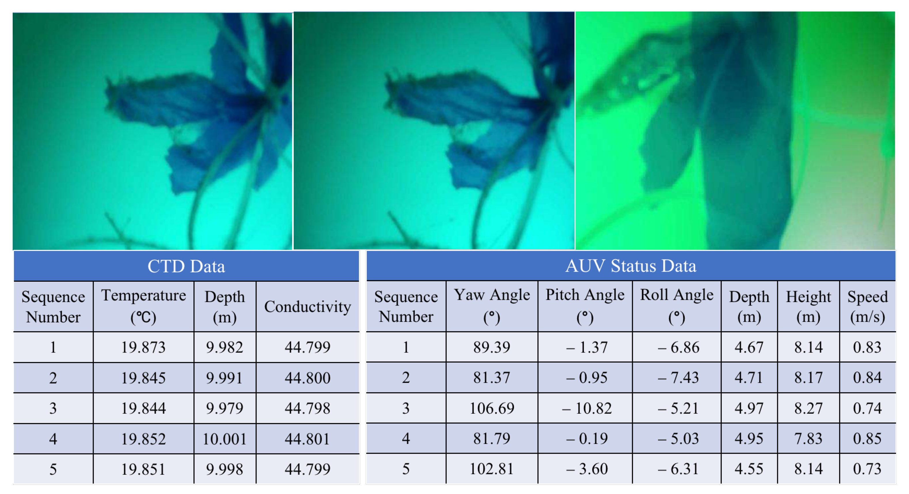
28]. Additionally, the network protocol stack SeaLinx is implemented in the embedded operating system of underwater acoustic modems, which are provided by Smart Ocean Technology Co., Ltd. In the sea trials, each node is equipped with one aforementioned acoustic modem, which operates at a frequency band between 21 and 27 kHz. To fully verify the performance of the SDDA protocol, we conduct two categories of experiments. In the first category of experiments: for the software parameters, we experiment with different numbers of data packets in respect of throughput. The number of data packets is 5, 10, 15, 20, 25, and 30, respectively. The length of the data packet is 544 B. Apart from those, we also trial with varying packet generation rate from 0.02 to 0.2 packet/s with regard to other performances mentioned above. The length of the data packet is 300 B. All the test data are recorded in the log files. In the other category of experiments: to testify the utility of the proposed protocol, we conduct experiments on different classes data of nodes, including image, CTD (conductivity, temperature, and depth), and UUV (unmanned underwater vehicle) status data, of which the image data size is 8 KB, the CTD data size is 50 B, and the UUV status data is 120 B.
Ocean field experiments are conducted at Daya Bay, Shenzhen. The water depth of the test site is around 10 m. The average height of the sea wave during the test is between 1 m and 2 m. The deployment area embraces wave, tide, and temperature variance. In experiment I, we dispose four terminal nodes within a radius of 3 km centered on BS, which is shown in
Figure 5, where one terminal node is mobile, moving at a speed of 2 to 3 knots. The distance between each terminal node and BS is about 3 km. In experiment II, we deploy three terminal nodes centered on BS, of which one node, equipped with an underwater camera, is 1.5 km away; another, as UUV, is 1.6 km away; and the third one, carrying a CTD, is 3.5 km away.
5.3. Results and Analysis
A. Simulation Results
In this subsection, we first analyze the throughput simulation results of the proposed protocol. Second, the comparison experiment results of the three protocols are discussed.
Throughput Results Analysis
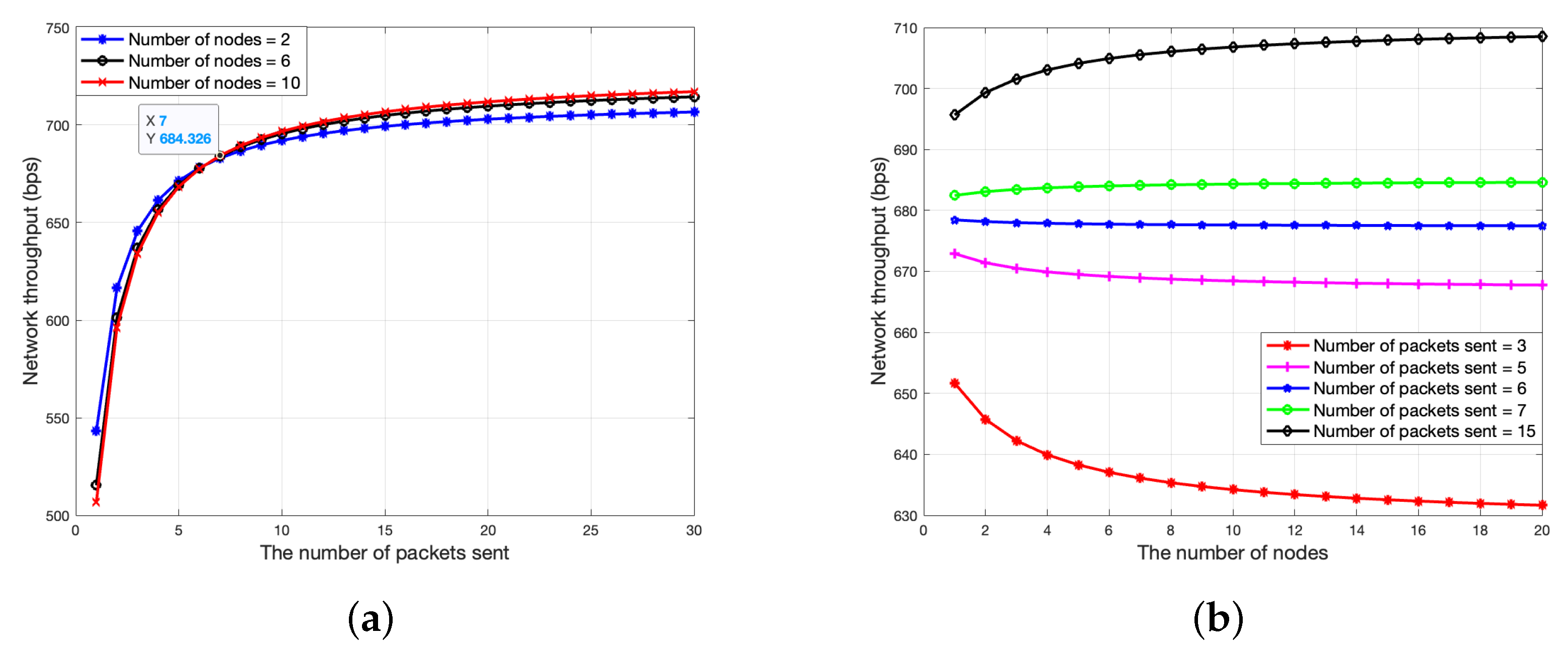
Figure 6 shows the simulation results of the SDDA protocol with respect to throughput. From
Figure 6, we can see that the throughput rises as the number of data packets sent by each node increases. When the number of data packets is less than 7, the throughput increases rapidly. Nevertheless, when the number of data packets is more than 7, the throughput tends to be stable and finally converges to a certain value. This is because when
, except for the data transmission phase, the additional overhead is negligible. Therefore, the throughput eventually approaches the maximum communication rate of the point-to-point link. From
Figure 6, we can see that the throughput declines with the number of nodes increasing in the case that the number of data packets issued is less than 7, but ascends with the number of nodes increasing in the case of the number of data packets issued being more than 7. This is because when the number of data packets transmitted by each node is small, as the number of nodes accessing the network increases, compared to the data transmission period, the reservation phase time increases more (i.e., more extra overhead). Thus, to achieve good throughput, the number of data packets to be sent by each node should be more than 7.
Simulated Comparison Experiment Results
Figure 7 compares the simulated channel utilization of the SDDA protocol with that of the other two MAC protocols, S-FAMA and TDMA. As shown in
Figure 7, our proposed scheme SDDA notably outperforms S-FAMA and TDMA on channel utilization. Because compared to S-FAMA, SDDA not only reduces the number of control packets, but also ensures conflict-free transmission, and multiple data packets can be sent out after each round of channel reservation. Compared to TDMA, SDDA utilizes the on-demand scheduling mechanism to make the best use of the channel, decreasing the waste of spare time. From
Figure 7, it is apparent that the channel utilization of both SDDA and TDMA raises with
increasing, and eventually becomes a constant value. This is because the proportion of channel time occupied by data packets gradually increases, and when the data traffic in the network is at full load, the channel utilization no longer increases. However, the channel utilization of S-FAMA declines when
is more than 0.07. This is because more collisions occur, bringing about more additional time being wasted.
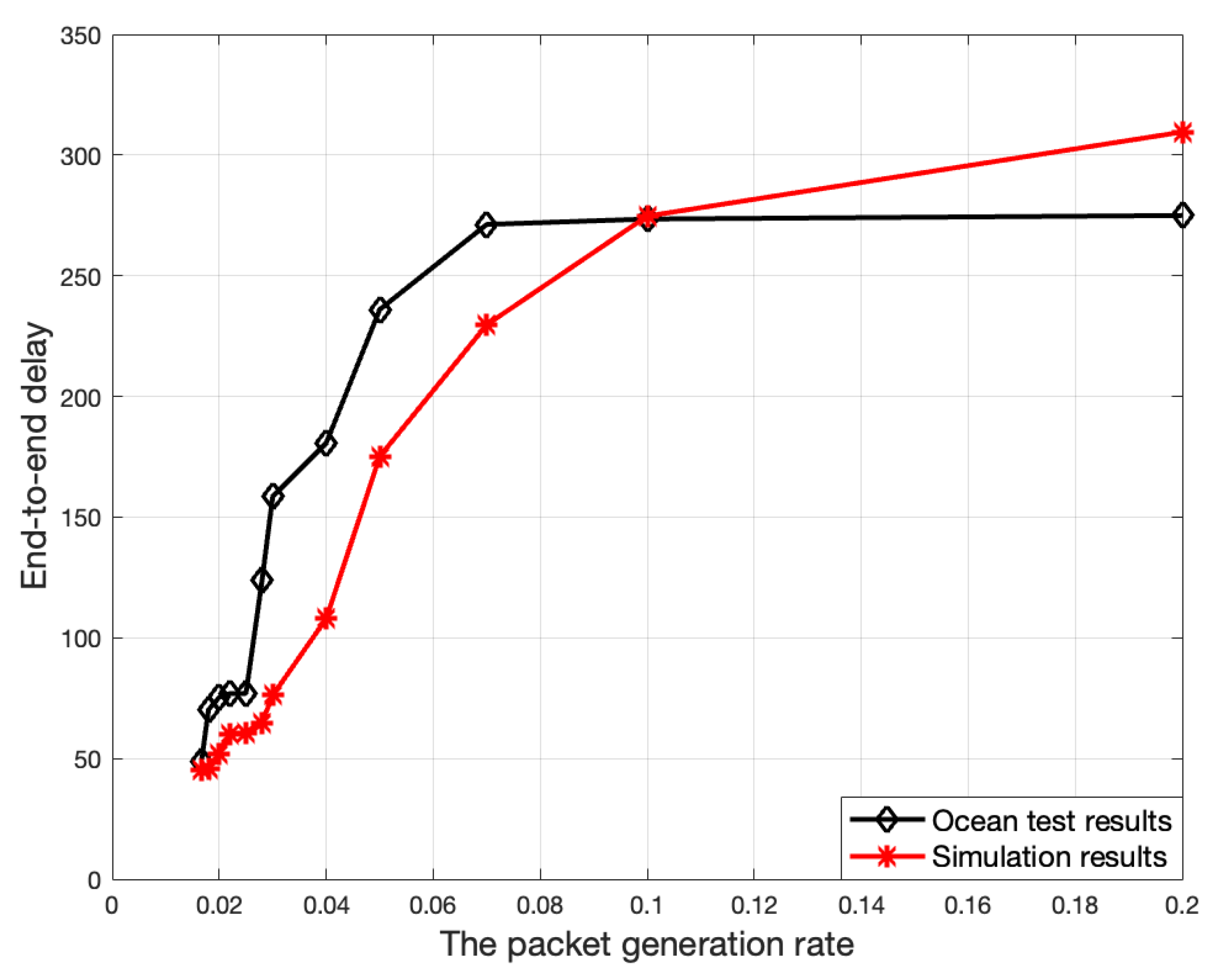
Figure 8 illustrates the changes in end-to-end delay over
. In
Figure 8, the end-to-end delay becomes longer as
goes up, owing to the queueing delay of data packets gradually increasing. In addition, more and more serious conflicts also exacerbate end-to-end delay performance for S-FAMA. As shown in
Figure 8, the SDDA protocol achieves the best performance in terms of end-to-end delay, in that each node can burst out all data packets in sending queue by every channel reservation in SDDA, while TDMA can only send one packet in each slot, and there are a great many of handshake clashes in S-FAMA, which greatly enlarges the end-to-end delay.
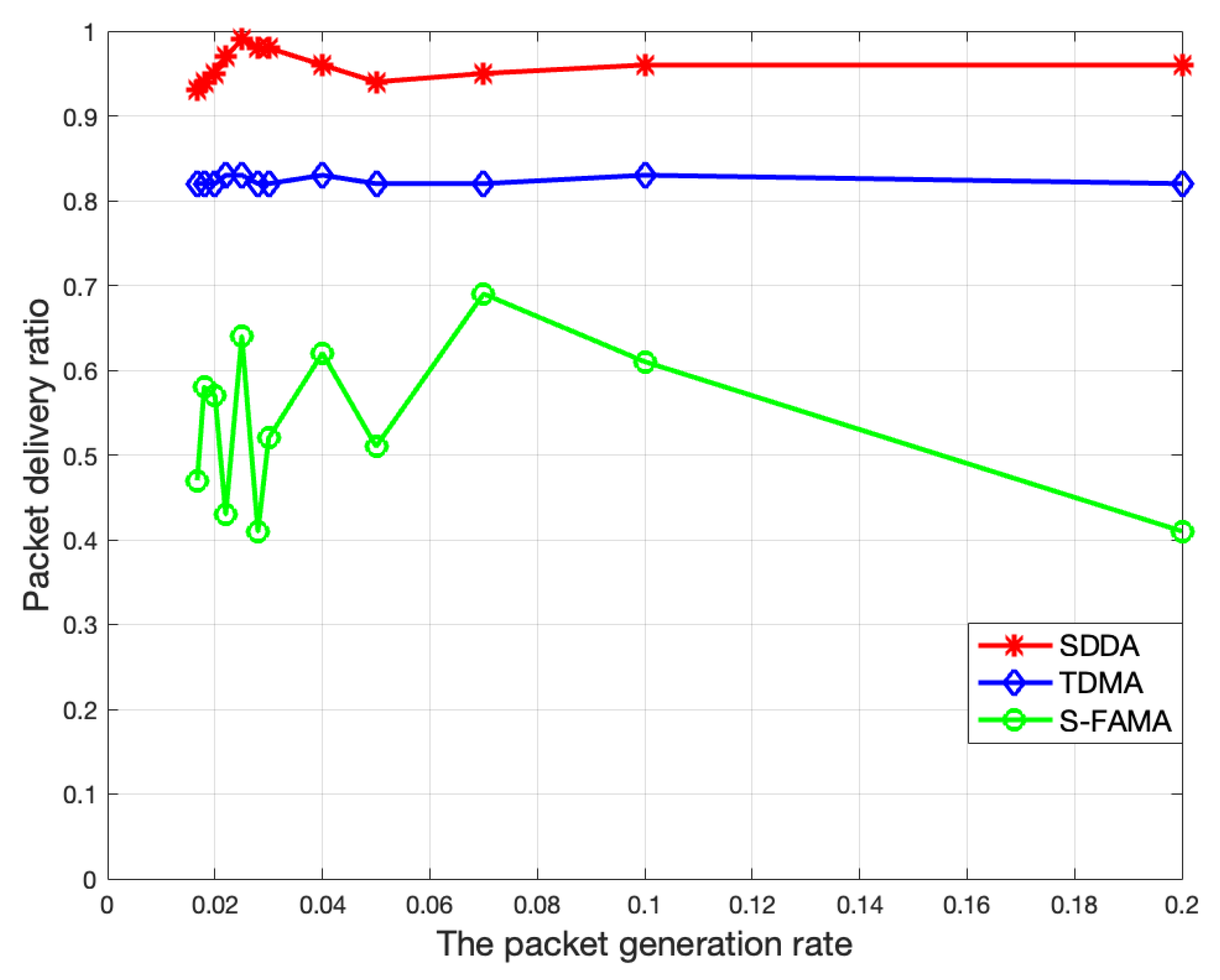
Figure 9 demonstrates the packet delivery ratio performance of these three protocols. From
Figure 9, we can see that the packet delivery ratio of SDDA and TDMA is essentially constant, linked to the packet loss rate specified in the simulation settings, but that of SDDA is higher on account of its acknowledgement-repeat mechanism. While in S-FAMA, the packet delivery ratio is relatively low, and there is a lot of fluctuation, in that control packets collisions become heavier and heavier, leading to multiple retransmissions of data packets failures, and thus data packets that fail to be retransmitted will be discarded.
Based on the above comparison experimental results, the performance of SDDA is significantly superior to the other two. However, in terms of energy efficiency, TDMA is the most energy-saving without transmitting additional control packets; compared to S-FAMA, SDDA only needs a small amount of control packets and completely avoids conflict to save energy. As can be seen from
Figure 7, when the packet generation rate is greater than 0.1, the channel utilization of SDDA exceeds 90%, and the proportion of control packets is less than 10%. SDDA’s extra energy consumption except data transmission is not high. Compared with TDMA, although SDDA consumes slightly more energy, its channel utilization is two times higher and end-to-end delay is three times lower, and to some extent, it guarantees the reliability of data transmission.
B. Ocean Field Experiment Results
In this subsection, we evaluate the performances of the SDDA protocol through two types of sea trials. In experiment I, we compare the results of real sea tests with those of simulation in regard to throughput, channel utilization, end-to-end delay, and packet delivery ratio of SDDA protocol. In experiment II, we verify the practicability of SDDA by collecting various underwater data in the built UW-WiFi network system.
Experiment I:
Figure 10 shows the results of ocean trial and the simulation on network throughput of the SDDA protocol in the same settings. It is apparent that the network throughput gradually rises and finally stabilizes with the increase in the number of data packets sent, which conforms with the throughput simulation results. However, through
Figure 10, we can obtain that the field trial results are slightly lower than the simulation results. This is because the underwater acoustic communication link is unstable due to the serious ocean conditions during the trial, resulting in a high bit error rate, which causes packet decoding failures and being dropped.
Figure 11 and
Figure 12 depict the simulation and sea test consequences of channel utilization and end-to-end delay on the proposed SDDA scheme, respectively. As the packet generation rate rises, it results in an increase in the number of data packets, thereby significantly increasing the time that the data occupy the channel and the data queueing delay in each round of transmission. Hence, the channel utilization and end-to-end delay increase as illustrated in
Figure 11 and
Figure 12. From
Figure 11, we can also see that the channel utilization eventually converges to a certain value. This is because the maximum number of packets sent by each node each time is fixed, and when the number of packets sent reaches the maximum, the channel utilization will no longer increase. The field experiment results are in line with the simulations on both of the two performances. When the number of packets sent is unlimited and tends to infinity (i.e., the packet generation rate tends to infinity), the channel utilization will be infinitely close to 100%, but the end-to-end delay will become considerable. Therefore, in practical applications, we should consider a trade-off between the two performances to choose the most appropriate packet generation rate based on the application requirements.
Figure 13 presents the simulation and sea field experiment results of the packet delivery ratio of the SDDA mechanism. From
Figure 13, we can observe that the packet delivery ratio holds steady at around 90%, and even reaches 100% once in a while. Compared to the results of the simulation, those of real sea tests are a little lower in
Figure 13. For the reason that underwater acoustic communication suffers from intermittent connectivity in consequence of harsh hydrological environment varying with time in real sea trials, which brings about erratic packet loss. Though, thanks to the mechanism of acknowledgment and retransmission in the SDDA protocol, the network has a low packet drop ratio.
Experiment II:
Figure 14 illustrates the data of various sizes from terminal nodes at different ranges. These test results from the real scenario, as demonstrated in
Figure 14, indicate that the proposed protocol effectively addresses the issue of diverse data needs of different functional nodes in real-world ocean applications by the on-demand scheduling scheme. Additionally, the trial also manifests that terminal nodes at different distances have an equal opportunity to send data in each transmission round. Thus, there will not be a situation where the short-range nodes frequently pre-empt the channel, resulting in the data backlog of long-range nodes. Therefore, the SDDA protocol achieves good fairness amongst terminal nodes. Apart from that, this protocol reduces energy usage to prolong the network lifetime by using fewer control packets and the conflict-free scheduling.


