Abstract
The main engineering machinery for the hydrodynamic lifting of seafloor mineral particles is rotor machinery with rotating impeller motion. It is important to study the rebound mechanism of collisions between particles and rotating walls to improve the accuracy of numerical simulation of rotor machinery. In this study, the law of motion change after collisions between particles and rotating walls is investigated using an experimental research method. The results show that the deflection angle of the particles after collision decreases with increases in the rotational speed of the wall, and the spin angular velocity increases with increases in the rotational speed of the wall. The normal velocity coefficient of restitution under the rotating wall is not affected by the rotational speed of the wall. The tangential coefficient of restitution under rotational boundary condition is smaller than the tangential coefficient of restitution under the stationary wall, and the higher the rotational speed, the closer it is to the coefficient of restitution under the stationary wall. During collision in the experiment, the main mode of contact between the particle and the rotating wall is sliding contact. Sliding friction between the particle and the rotating wall results in energy loss in the tangential velocity of the particle, and also provides energy for deflection of the particle’s trajectory and increased kinetic energy from the spin angular velocity; sliding friction loss is affected by the speed of the wall.
1. Introduction
The phenomenon of solid–liquid two-phase flow exists widely in production processes in nature and modern industry. The overcurrent mechanical components that transmit solid–liquid mixed media undergo fluid wear that cannot be ignored. The transmission of the solid–liquid mixed medium in construction machinery is mostly rotor machinery consisting of the main mechanical flow components for centrifugal pump impellers, which are also the parts with the most serious wear. At present, the main way to study erosion wear in flow components is the combination of equivalent experiments and numerical simulation. Therefore, it is of great importance to study the rebound mechanism of particle wall collisions under the condition of a rotating wall for accuracy in numerical simulation of this kind of construction machinery.
In 1881, Hert [1] studied collision between vertical upward particles and a wall and determined the relationship between instantaneous contact stress and interaction force. In 1975, Maw, Barber and J.N [2] extended Hert’s experimental range to the collision of particles with inclined planes and specified that the trajectory of particles after a collision was mainly determined by collision angle and radius of rotation. Peter Mueller et al. [3] selected three kinds of spherical particles with different water contents to impact a hardened steel plate. The results showed that the three material samples all had elastic–plastic impact material properties, and the coefficient of restitution decreased significantly with increases in the water content. Fohanno [4] set up an experimental facility consisting of a collisional flow of large spherical glass particles (3 mm in diameter) in a vertical convergent channel. The necessity for an accurate knowledge of particle–wall collision properties was pointed out. Non-negligible effects of spin-induced forces on large particles were also observed.
Many scholars have also studied the influence of different wall materials and wall roughness on the rebound characteristics of particle collisions. Krull [5] conducted single-particle impact tests with spherical zirconia particles on polished and untreated titanium alloy surfaces, and found that the coefficient of restitution in air decreased with increasing roughness, while it increased in collisions in water. Gibson [6] used three kinds of particles—coke particles, polyethylene particles, and polystyrene particles—and four kinds of plates—metal plates, low viscosity silica gel surfaces, high viscosity silica gel surfaces, and a surface partially covered with coke particles—as the experimental objects. They demonstrated that in the normal collision direction, the main factors affecting the coefficient of restitution were the material properties of the particles, and they found that the surface roughness and flatness of the wall affected the particle collision rebound angle. Sommerfeld and Huber [7] studied a model of collision between small particles and a wall, as well as the relationship between particle coefficient of restitution and wall roughness, particle rotation angular velocity, and friction coefficient. It was found that when the particle diameter was small (100–500 μm), particle diameter and wall surface roughness had a significant effect on the coefficient of restitution. The larger the particle size, the smaller the coefficient of restitution, and as surface roughness increased, particle size had a smaller effect on the coefficient of restitution. Chen et al. [8] studied the law of rebound of collisions between particles with different particle sizes and walls made of different materials for drywall, and they concluded that when particle size was large, the coefficient of restitution of the particle–wall collision rebound was independent of the particle size and related to the medium, collision angle, wall material, and collision speed. They also analyzed the law of change of the surface friction coefficient under different collision conditions. Wang et al. [9,10] analyzed the effects of particle sphericity and wall roughness on collision velocity and pointed out that, for non-spherical particles or rough walls, the coefficient of restitution and the friction coefficient both decreased with increases in the incidence angle. Newton [11] defined the coefficient of restitution as the ratio of rebound velocity to incidence velocity, which provided a quick method for later analysis of energy change in a particle–wall collision. Following this, researchers studied the coefficient of restitution and summarized different particle collision rebound models in a large number of experiments. H. Dong [12] built a device that could release a ball with or without initial rotation to study the oblique impact of a steel ball on a plane. Using high-speed camera records, the normal and tangential restitution coefficients, impact ratio, and dynamic friction coefficient were measured. It was pointed out that the oblique impact of a ball without initial rotation on a plane was more in line with rigidity theory. Grant and Tabakoff [13] discussed the velocity, tangential velocity, normal velocity, and collision angle coefficient of restitution of particles with different diameters at different incidence angles, and they established the Grant particle–wall collision rebound mathematical model, which is currently widely used.
Many scholars have also studied the rotational motion of particles. Leszczyński [14] found experimentally that when inter-particle friction is neglected, the kinetics of particle motion behaves as splash-type kinetics, and the rebound between particles is more intense. When inter-particle friction is considered, it causes spin motion in the particles, which causes different particle cluster structures to form between particles and causes the particles to gain kinetic energy for spin motion during frictional collision. Li et al. [15] studied the rotational dynamics of finite-size ellipsoidal particles in different fluid flows via numerical simulation. The results show that oblong and oblate particles rotate freely around their mass centers in uniform flow, linear shear flow and wall turbulence. For an ellipsoid rotating in linear shear flow, a steady state can be regarded as a nonlinear combination of rotation in uniform flow and Couette flow. It was observed that the longest particle axes are perpendicular to or have a large angle with local flow direction in the flow-gradient plane, which leads to large drag force. Wang et al. [16] found that the observed grain rotations in simple shear experiments can be decomposed into two parts. One part of the rotation of each grain is a result of the imposed affine macroscale deformation field, which contributes an overall rigid body rotation. Another part is the microscale phenomena of individual grain spin called microrotation. Shear force will induce particles to produce diffusive microrotation, and enhancement and weakening of this microrotation depend on the volume fraction of the particles and the friction between particles. At the same time, these two factors will also affect the rotational freedom of particles.
Foerster [17] used the tangential velocity recovery coefficient, normal coefficient of restitution, and friction coefficient to establish a more simplified model to predict the motion state of particles. Aman et al. [18] proposed a semi-empirical method to calculate the coefficient of restitution, which was derived by fitting a combination of two different methods with essentially the same theoretical and actual coefficients of restitution. Zhang et al. [19] constructed a new model consisting of two parts: the use of fractal theory combined with empirical erosion formula to construct the morphology of a rough wall surface, and the use of the regression subdivision method to determine the contact point between particles and wall surface. Tabakoff et al. [20] carried out particle collision experiments on 410 stainless steel, 2024 aluminum alloy, and 6A1–4V titanium alloy using laser measurement, and they obtained a collision rebound model for three materials on a dry surface. Hastie [21] used high-speed video to capture the random behavior of irregularly shaped polyethylene particles in a three-dimensional environment to determine the coefficient of restitution. The angular displacement and angular velocity of the particles were determined through experiments, and a model for determining the coefficient of restitution was given.
It can be seen that in the calculation of solid–liquid two-phase flow in rotating machinery, the collision rebound models adopted are based on the properties of the static wall. There are few experimental studies on collision rebound under rotating boundary conditions. However, rotating walls change particle motion after collisions. There are errors when the existing model is directly used to calculate two-phase flow in rotating machinery. Therefore, collision rebound experiments between particles and rotating walls were carried out. The results can be used to correct the collision rebound model for particles and walls inside rotating machinery.
2. Experiment
2.1. Experimental Setup
The principles of the experimental device for particle collisions with a rotating wall are shown in Figure 1. The experimental system consists of a particle-spraying device, a rotating wall table, and a high-speed camera acquisition and processing system. The rotating wall table is composed of a rotary table and a collision wall, and the collision wall is a circular metal wall. The rotary table is driven by a stepper motor, which drives the collision wall to rotate synchronously, while an electric signal is used to control the stroke of the stepper motor with precise rotational speed control. The particle-spraying device is connected to a pressure pump through a hose, and the pressure pump provides air pressure for the particle-spraying device to promote the movement of a telescopic rod to eject particles at marker points. The input air pressure is adjusted using a pressure-regulating valve to ensure the incidence velocity of the particles remains unchanged. Two high-speed cameras with frame rates of 1000 and 2000 frames per second are used to capture the front view and side view of the experiment, respectively.
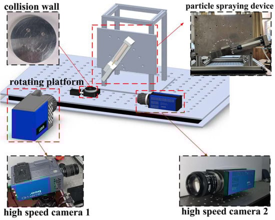
Figure 1.
Flowchart for correcting the roll forming process design.
The video of the experimental process captured by the high-speed cameras is transferred to a computer, and differences in object position in the target area are compared frame by frame using Molysis motion analysis software to obtain the circle center coordinates of the time of particle collision, the circle center coordinates of the frame before the collision, and the circle center coordinates of the frame after the collision. The difference between the coordinates is divided by the time interval between the two frames to find the values of the incidence velocity and the rebound velocity of the particle.
2.2. Experimental Materials and Working Conditions
In this experiment, 316 stainless steel ball particles with a diameter of 7 mm are used. The collision wall is a circular wall made of 6061 aluminum alloy with a diameter of 100 mm. The rotational speed of the collision wall is set as 10°/s, 30°/s or 50°/s. Under these different rotational speed conditions, particle incidence experiments were carried out from six incidence angles of 15°, 30°, 45°, 60°, 75° and 90°. In each condition, 16 sets of experiments were carried out to eliminate random errors. The material properties are shown in Table 1 [22].

Table 1.
Material properties of particles and walls.
According to Sondergaard et al. [23], the kinematic coefficient of restitution of a particle is related to the ratio of the particle diameter and wall thickness (d/Dp), and its value must be not less than four to ensure that the coefficient of restitution tends to be stable. Therefore, the thickness of the 6061 aluminum alloy circular wall is 30 mm.
2.3. Definition of Particle Motion Parameters
A three-dimensional Cartesian coordinate system is established with the position of the collision point as the origin, and the incidence velocity and rebound velocity are expressed in the form of vector coordinates, and the rebound angle and deflection angle can be calculated. The coordinate value before incidence , the coordinate value after rebound , the incidence velocity , the normal component and tangential component of the incidence velocity, the rebound velocity , the normal component and tangential component of the rebound velocity, the spin angular velocity , the incidence angle , the rebound angle and the deflection angle of the particle are shown in Figure 2.
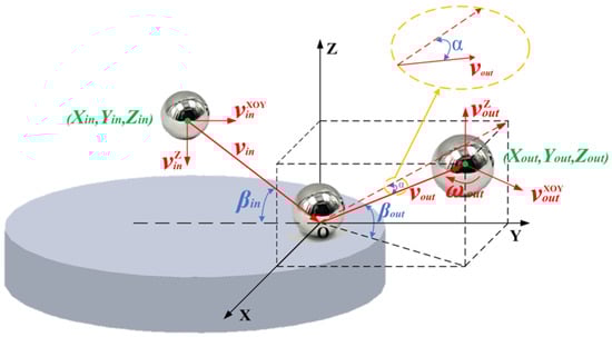
Figure 2.
Particle motion parameters.
3. Results and Discussion
In this study, particle collisions with a rotating wall at different incidence angles are examined. By analyzing the deflection angle and spin angular velocity after particle collision, the influence of the rotating wall on the particle’s motion state after collision is studied. By analyzing the velocity coefficient of restitution, the collision angle coefficient of restitution, and the change in kinetic energy before and after collision, the influence of the rotating wall on the change in kinetic energy before and after particle collision is studied.
3.1. Deflection Angle and Spin Angular Velocity
Study of the deflection angle and spin angle velocity after particle collision aids the analysis of the effect of wall rotation on the motion state of particles after bouncing. The definition of the deflection angle is shown in Figure 2. The angle between the rebound velocity vector and the YOZ plane, which is the deflection angle , is calculated as follows:
The spin angular velocity of a particle after a collision rebound can be determined by counting the number of frames n required to complete a 180° rotation at the marked point on the particle. The units are rad/s.
Figure 3 describes the influence of different wall revolution speeds on the deflection angle after particle rebound. As shown in Figure 3, particle deflection angle decreases as wall revolution speed increases. This phenomenon may arise because the normal component of the particle incidence velocity is constant at the same incidence angle, making the contact time between the particle and the wall constant. In the case of an increasing revolution speed, frictional displacement between the particle and the wall increases, which causes kinetic energy loss of the particle in the X-axis direction to increase, resulting in a decrease in particle deflection angle. In addition, deflection angle tends to increase gradually with increases in the particle incidence angle in general. This is due to the fact that at a constant wall revolution speed, as incidence angle increases, the normal component of particle incidence velocity gradually increases. This causes the contact time between particle and wall to decrease, velocity energy loss of the particle in the X-axis direction caused by friction to decrease, and deflection angle to increase.
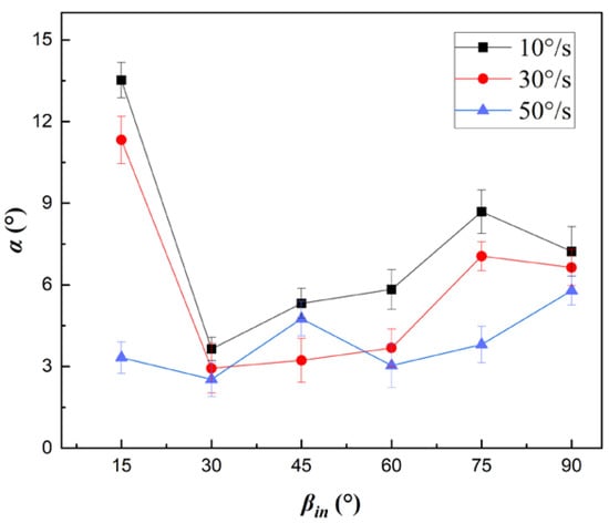
Figure 3.
Effect of rotational speed on deflection angle α.
Figure 4 depicts variation in spin angular velocity of the particle with variation in angle of incidence after collision with the rotating wall. As wall revolution speed increases, angular velocity of the particle spin gradually increases. Wall rotation makes the wall do work on the particle, and the energy generated by this work provides the energy for the increase in particle spin speed. As the speed of wall rotation increases, the amount of work done increases, making it possible to increase the energy available to the particles and thus increasing the angular velocity of their spin.
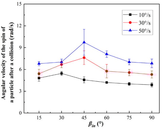
Figure 4.
Rotational angular velocity of particles after collision at different rotational speeds.
In studies of particle collisions with static dry walls, it is generally accepted that there is a slip–viscosity bifurcation in static dry wall conditions. That is, as the angle of incidence becomes larger, contact between particles and the wall gradually changes from a slip state to a viscous state. To further investigate whether slip–viscosity bifurcation also exists when particles collide with a wall under rotating wall conditions, the tangential elastic compliance theory analysis in Maw [2] is applied to the processing of experimental data in this study. is the characterization function of the collision incidence angle, and is the characterization function of the corresponding rebound angle. These functions are defined as follows:
is the normal velocity coefficient of restitution of the particle, defined as the ratio of the velocity component of the bounce velocity in the Z-axis direction to the velocity component of the incidence velocity in the Z-axis direction, via the following equation:
Figure 5 displays the fitting of Maw’s analysis method to the experimental data. It can be seen from the figure that under the condition of a static wall surface, there is a turning point in the value of the fitting line of , which indicates that with changes in the incidence angle, the mode of contact between particles and wall surface tends to change from sliding to viscous. The situation under a rotating wall condition is different from that under the stationary wall condition. The fitting line under the rotating wall condition tends to be a straight line, indicating that the mode of contact between particles and wall surface is mainly sliding contact; that is, the friction between the particles and the wall is mainly sliding friction.
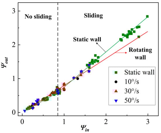
Figure 5.
Processing results based on tangential compliance theory.
3.2. Particle Velocity Coefficient of Restitution and Angle Coefficient of Restitution
The incidence and rebound velocities of particles can be decomposed into the normal velocity and the tangential velocity. The ratio of normal velocity to tangential velocity before and after collision is the ratio of the normal coefficient of restitution and the tangential coefficient of restitution. The definition of the two ratios is as follows:
The collision angle coefficient of restitution is defined as the ratio of the collision angle of the particle before and after the incident. As shown in Figure 2, the angle between the rebound velocity vector and the plane XOY is the rebound collision angle , while the incidence angle is still the angle between the incidence velocity and the Y axis in the coordinate system. The ratio is the collision angle coefficient of restitution . The calculation formula is as follows:
Figure 6 describes the velocity recovery coefficient of particles at different rotational speeds of the wall. As can be seen from Figure 6a, the normal velocity coefficient of restitution of particles under static wall conditions does not change significantly from that under rotating wall conditions. This indicates that the normal velocity coefficient of restitution is only related to the material properties between particle and wall in both the rotating wall condition and the stationary wall condition.
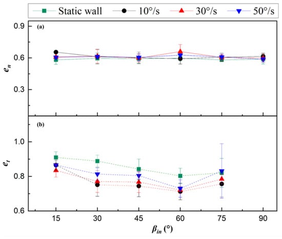
Figure 6.
Velocity coefficient of restitution of particles at different rotational speeds: (a) Normal velocity coefficient of restitution; (b) Tangential velocity coefficient of restitution.
However, the tangential velocity coefficients of restitution of particles under different rotational speeds of the wall have significant differences in values and similar variation trends. As shown in Figure 6b, the tangential velocity coefficient of restitution has a tendency to decrease and then increase with increases in the incidence angle. The larger the rotational speed of the wall, the closer the tangential velocity coefficient of restitution of the particles to the experimental result curve for the static wall condition, while the smaller the rotational speed of the wall, the smaller the tangential velocity coefficient of restitution of the particles. As can be seen from Figure 3, when the rotational speed of the wall increases, the deflection angle of the particle decreases. At the same time, for the tangential velocity of the particle after bouncing, the Y-axis component increases and the X-axis velocity component decreases, while the work done by the friction between particle and wall mainly affects velocity energy loss in the X-axis direction. When the rotational speed of the wall increases, the tangential velocity component in the X-axis direction takes up a smaller proportion, and tangential velocity is less affected by sliding friction loss, so the tangential velocity coefficient of restitution increases with increases in rotational speed. In addition, compared with the stationary wall condition, the velocity energy loss of the tangential velocity of particles in the X-axis direction under the rotating wall condition is due to sliding friction, making the tangential velocity coefficient of restitution under the rotating wall condition smaller than that under the stationary wall condition.
Figure 7 describes the influences of different rotational speeds of the wall on the particle collision angle coefficient of restitution. It can be seen from Figure 7 that under three rotational speed conditions of the wall, the angle coefficient of restitution increases with increases in the incidence angle. At the same time, the value of the angle coefficient of restitution is maintained in a higher range, indicating that the rebound angle of the particles before and after collision changes less. Under the static wall condition, the angle coefficient of restitution of the particles is smaller than that under the rotating wall condition. With increases in the incidence angle, the range of variation in the coefficient value is larger, and the difference relative to the angle coefficient of restitution under the rotating wall condition is smaller. The angle coefficient of restitution is mainly used to measure the contact mode of particles with the wall, and indicates that rotational motion of the wall affects the contact mode between particles and wall at the moment of collision, which is also consistent with the conclusion shown in Figure 5.
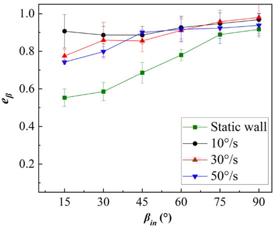
Figure 7.
Influences of different rotational speeds on the particle angle coefficient of restitution.
3.3. Effect on Particle Kinetic Energy
The value of the kinetic energy coefficient of restitution represents the ratio between the total kinetic energy of the particle after collision and the total kinetic energy of the particle before collision. The definition formula is as follows:
In the expression, and are the total kinetic energies of the particle at incidence and rebound, respectively. The definition formula is as follows:
In the expression, and are the linear velocity kinetic energy component and the rotational velocity kinetic energy component of the total kinetic energy of the particle, respectively. When the particles are ejected, they rotate only after coming into contact with the rotating wall. So the total incidence kinetic energy and the total rebound kinetic energy of the particle can be defined as follows:
In the expression, m is the mass of the particle, and are the linear velocities of the particle during incidence and rebound, respectively, and is the rotational velocity of the particle during rebound. is the rotational inertia of the particle and R is the radius of the particle.
Figure 8a depicts the effect of the rotational speed of the wall on the kinetic energy coefficient of restitution of the particle. As shown in the figure, the kinetic energy coefficient of restitution of the particle gradually decreases as the incidence angle increases, indicating that the relative amount of kinetic energy lost by the particle is greater at a large collision angle under the rotating wall condition. The kinetic energy coefficient of restitution increases with increases in rotation speed, and the kinetic energy coefficient of restitution under the rotating wall condition is greater than that under the static wall condition. This shows that energy is obtained by friction between the particle and the rotating wall during the collision process, and the obtained energy mainly increases the kinetic energy of the spin angle velocity of the particle; the amount of increase grows with increases in the rotational speed of the wall, so the energy coefficient of restitution increases with increases in the rotational speed of the wall.
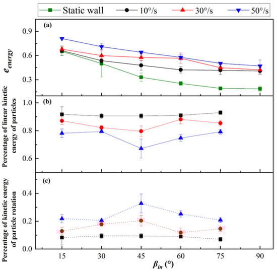
Figure 8.
The change in kinetic energy coefficient of restitution at different rotational speeds and the proportion of translational and rotational kinetic energy for particles after collision: (a) Kinetic energy coefficient of restitution; (b) Percentage of linear kinetic energy; (c) Percentage of kinetic energy.
Figure 8b,c describe the proportions of linear velocity kinetic energy and angular velocity kinetic energy of the particle in the total kinetic energy of the rebound. The proportion of the kinetic energy of the linear velocity of the particle is inversely related to the rotational speed of the wall. The proportion of particle rotational kinetic energy is positively correlated with the rotational speed of the wall. This shows that wall rotation provides energy for increases in the particle spin angle, which increases the proportion of particle rotational kinetic energy; this is also the same as the trend of change in the angular velocity shown in Figure 4. The kinetic energy of the particle spin angular velocity increases with increases in the incidence angle, and the rotational speed of the particle first increases and then decreases. For the case of low wall rotational speed, this trend is not obvious and the curve is relatively flat. Under the rotating wall condition, even if particles can obtain rotational kinetic energy from friction work with the wall, the kinetic energy obtained after rebound still cannot make up for the kinetic energy lost during the collision process, and the kinetic energy coefficient of restitution is still less than 1.
Energy loss during particle collision can be divided into the normal direction and the tangential direction, namely, vertical direction on the Z axis and tangential direction in the XOY plane. Energy loss in the normal direction is mainly direct contact energy loss between particles and the wall in the collision process. On the tangent plane of the collision point, the main cause of energy loss is friction work. Before analyzing energy loss in both directions, it is necessary to define the energy loss in both directions using the previously defined normal and tangential restitution coefficients and the spin angular velocity after particle collision. The definition of normal contact energy loss and tangential friction energy loss is as follows:
Kinetic energy loss on the tangent plane includes both energy from sliding friction to rotate the particles after collision and energy of sliding friction loss. Therefore, sliding friction loss should be subtracted from total energy before and after collision to find the particle kinetic energy in the tangent plane. Hence, energy loss on the tangent plane is finally defined as follows:
Using the above formula, the ratio of contact energy loss to initial kinetic energy and the ratio of sliding friction loss to initial kinetic energy at wall rotational speeds of 10°/s, 30°/s, and 50°/s are calculated. The distribution of the incidence angle is shown in Figure 9.
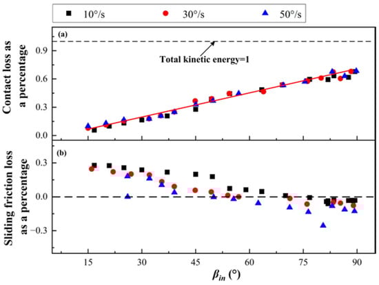
Figure 9.
Ratio of particle kinetic energy loss to total kinetic energy at different rotational speeds: (a) Contact loss as a percentage; (b) Sliding friction loss as a percentage.
From Figure 9a, it can be seen that contact loss from particle–wall collision increases with increases in the incidence angle. When the incidence angle is greater than 55°, contact loss is the main form of energy loss in the collision process. There is no obvious distinction between the experimental results at different wall rotational speeds and the trend is the same, indicating that contact energy loss of particles against a rotating wall does not change with the rotational speed of the wall; that is, contact energy loss is always only related to the material properties of the particles and the wall, and the normal velocity recovery coefficient is the same. The ratio of contact energy loss to total energy is positively correlated with incidence angle. The data points in the figure show the same linear trend distribution.
From Figure 9b, it can be seen that with increases in the incidence angle, the relative amount of sliding friction loss gradually decreases, and the value of sliding friction loss ranges from 0.3 to –0.3. A negative value represents positive work of the rotating wall on the particle. With increases in the rotational speed of the wall, the proportion of sliding friction energy loss decreases. This is because the larger the rotational speed of the wall, the greater the working distance of the sliding friction force, and the greater the energy of the friction function in the kinetic energy of the particle’s spin angular velocity, so the proportion of sliding friction energy loss gradually decreases.
Combining the analysis of the change in the deflection angle in Figure 3 and the analysis of the tangential restitution coefficient in Figure 6, it can be inferred that sliding friction between the rotating wall and the particles causes energy loss in the tangential velocity kinetic energy of the particles and provides energy for increases in the spin angular velocity kinetic energy of the particles.
4. Conclusions
In this study, a particle–wall collision rebound experiment under a rotating boundary condition is carried out. The effects of different rotational speeds of the wall on the deflection angle, spin angular velocity, velocity, and angle coefficient of restitution of the particles, the energy coefficient of restitution of the particles, the energy ratio, and the energy loss after rebound are studied. The experimental results can be used to correct the wall collision model for calculation of solid–liquid two-phase flow in rotating machinery. The following conclusions are obtained:
- (1)
- The deflection angle decreases with increases in wall rotational speed and increases with increases in incidence angle. The spin angular velocity of particles gradually increases with increases in wall rotational speed, and angular velocity kinetic energy of particles also increases. The contact mode between particles and rotating wall is mainly slip contact, and there is no obvious slip–viscous bifurcation phenomenon.
- (2)
- Under a rotating wall condition, the normal velocity coefficient of restitution of the particles is only related to the material properties between the particles and the wall, and is independent of the rotational speed of the wall. The tangential velocity coefficient of restitution of the particles increases with increases in the rotational speed of the wall, and is smaller than that under the static wall condition. With increases in the incidence angle, the difference in angle coefficient of restitution at different wall rotational speeds is smaller, and it is greater than the angle coefficient of restitution under the static wall condition.
- (3)
- The kinetic energy coefficient of restitution of the particles increases with increases in the rotational speed of the wall, and is greater than the coefficient of restitution under the static wall condition. There is still energy loss during collision between particles and the rotating wall, which is contact energy loss in the normal direction and sliding friction loss. The proportion of contact energy loss gradually increases with increases in incidence angle, and the change is independent of the rotational speed of the wall. The proportion of friction energy loss changes from positive to negative with increases in incidence angle. When the proportion is negative, sliding friction begins to do positive work on the particles. As the rotational speed of the wall increases, the energy obtained by particles from sliding friction increases, and the proportion of sliding friction loss decreases.
Author Contributions
Conceptualization, Y.L., Z.L. and G.Z.; Data curation, X.Z.; Formal analysis, Y.L., Z.L. and G.Z.; Funding acquisition, Y.L.; Investigation, Y.L., G.Z., Z.L. and G.Z.; Methodology, G.Z.; Project administration, Y.L.; Resources, Y.L.; Software, G.Z.; Supervision, Y.L. and Z.L.; Validation, G.Z.; Visualization, G.Z.; Writing—original draft, G.Z.; Writing—review and editing, Y.L., Z.L. and G.Z. All authors have read and agreed to the published version of the manuscript.
Funding
This research was funded by the National Key R&D Program of China (No. 2022YFE0126600), and the Key Research and Development Program of Zhejiang Province (No. 2022C01194).
Institutional Review Board Statement
The study did not require ethical approval.
Informed Consent Statement
The study did not involve humans.
Data Availability Statement
The data presented in this study are available on request from the corresponding author. Due to the huge amount of data, it is not convenient to save to publicly archived datasets.
Conflicts of Interest
The authors declare no conflict of interest.
Abbreviations
| Mass | |
| Radius | |
| Rotational inertia | |
| Deflection angle | |
| Incidence angle | |
| Rebound collision angle | |
| Spin angular velocity of a particle | |
| Incidence velocity | |
| Rebound velocity | |
| Normal component of the incidence velocity | |
| Tangential component of the incidence velocity | |
| Normal component of the rebound velocity | |
| Tangential component of rebound velocity | |
| Characterization function of the incidence angle | |
| Characterization function of the rebound angle | |
| Total kinetic energies before the incidence | |
| Total kinetic energies after the rebound | |
| Linear velocity kinetic energy component | |
| Rotational velocity kinetic energy component | |
| Normal contact energy loss | |
| Tangential friction energy loss | |
| Sliding friction loss | |
| Normal velocity coefficient of restitution | |
| Tangential velocity coefficient of restitution | |
| Collision angle coefficient of restitution | |
| Kinetic energy coefficient of restitution |
References
- Hertz, H. Über die Berührung fester elastischer Körper. J. Für Reineund Angew. Math. 1881, 92, 156–171. [Google Scholar]
- Maw, N.; Barber, J.; Fawcett, J. The oblique impact of elastic spheres. Wear 1976, 38, 101–104. [Google Scholar] [CrossRef]
- Mueller, P.; Antonyuk, S.; Stasiak, M.; Tomas, J.; Heinrich, S. The normal and oblique impact of three types of wet granules. Granul. Matter 2011, 13, 455–463. [Google Scholar] [CrossRef]
- Fohanno, S.; Oesterlé, B. Analysis of the effect of collisions on the gravitational motion of large particles in a vertical duct. Int. J. Multiphas. Flow 2006, 161, 22–31. [Google Scholar] [CrossRef]
- Krull, F.; Mathy, J.; Breuninger, P.; Antonyuk, S. Influence of the surface roughness on the collision behavior of fine particles in ambient fluids. Powder Technol. 2021, 392, 58–68. [Google Scholar] [CrossRef]
- Gibson, L. Measurement and Modeling the Coefficient of Restitution of Char Particles under Simulated Entrained Flow Gasifier Conditions. Ph.D. Thesis, Gradworks, The Pennsylvania State University, State College, PA, USA, 2013. [Google Scholar]
- Sommerfeld, M.; Huber, N. Experimental analysis and modelling of particle-wall collisions. Int. J. Multiphas. Flow. 1999, 25, 1457–1489. [Google Scholar] [CrossRef]
- Chen, X.; Ji, L.; Li, Y. Experimental and theoretical analysis of large particle–wall collision with different metal plates. J. Braz. Soc. Mech. Sci. Eng. 2022, 44, 1–14. [Google Scholar] [CrossRef]
- Wang, J.; Zhang, M.; Feng, L.; Yang, H.; Wu, Y.; Yue, G. The behaviors of particle-wall collision for non-spherical particles: Experimental investigation. Powder Technol. 2020, 363, 187–194. [Google Scholar] [CrossRef]
- Wang, J.; Yang, H.; Feng, L.; Zhang, M.; Wu, Y.; Yue, G. The behaviors of particle-wall collision for non-spherical particles: Modeling analysis. Powder Technol. 2020, 366, 137–143. [Google Scholar] [CrossRef]
- Newton, I. Newtons Principia: The Mathematical Principles of Natural Philosophy; University of California Press: Berkeley, CA, USA, 2014. [Google Scholar]
- Dong, H.; Moys, M. Experimental study of oblique impacts with initial spin. Powder Technol. 2006, 161, 22–31. [Google Scholar] [CrossRef]
- Grant, G.; Tabakoff, W. Erosion Prediction in Turbomachinery Resulting from Environmental Solid Particles. J. Aircr. 1975, 12, 471–478. [Google Scholar] [CrossRef]
- Leszczyński, J.S. Sensitivity analysis of the dynamics of fine and ultrafine particles using DEM. Nonlinear Dyn. 2023, 111, 2591–2605. [Google Scholar] [CrossRef]
- Li, R.-Y.; Cui, Z.-W.; Huang, W.-X.; Zhao, L.-H.; Xu, C.-X. On rotational dynamics of a finite-sized ellipsoidal particle in shear flows. Acta Mech. 2018, 230, 449–467. [Google Scholar] [CrossRef]
- Wang, D.; Nejadsadeghi, N.; Li, Y.; Shekhar, S.; Misra, A.; Dijksman, J.A. Rotational diffusion and rotational correlations in frictional amorphous disk packings under shear. Soft Matter 2021, 17, 7844–7852. [Google Scholar] [CrossRef] [PubMed]
- Foerster, S.F.; Louge, M.Y.; Chang, H.; Allia, K. Measurements of the collision properties of small spheres. Phys. Fluids 1994, 6, 1108–1115. [Google Scholar] [CrossRef]
- Aman, S.; Mueller, P.; Tomas, J.; Kozhar, S.; Dosta, M.; Heinrich, S.; Antonyuk, S. Combined viscoelastic and elastic wave dissipation mechanism at low velocity impact. Adv. Powder Technol. 2016, 27, 1244–1250. [Google Scholar] [CrossRef]
- Zhang, R.; Li, Y.; Liu, Y. Improvement and application of a two-dimensional fractal particle-wall collision model. Powder Technol. 2022, 411, 117–910. [Google Scholar] [CrossRef]
- Tabakoff, W.; Kotwal, R.; Hamed, A. Erosion study of different materials affected by coal ash particles. Wear 1979, 52, 161–173. [Google Scholar] [CrossRef]
- Hastie, D.B. Experimental measurement of the coefficient of restitution of irregular shaped particles impacting on horizontal surfaces. Chem. Eng. Sci. 2013, 101, 828–836. [Google Scholar] [CrossRef]
- Martienssen, W.; Warlimont, H. Handbook of Condensed Matter and Materials Data, 1st ed.; Harbin Institute of Technology Press: Harbin, China, 2014; pp. 192–193, 231–237. [Google Scholar]
- Sondergaard, R.; Chaney, K.; Brennen, C.E. Measurements of Solid Spheres Bouncing Off Flat Plates. J. Appl. Mech. 1990, 57, 694–699. [Google Scholar] [CrossRef]
Disclaimer/Publisher’s Note: The statements, opinions and data contained in all publications are solely those of the individual author(s) and contributor(s) and not of MDPI and/or the editor(s). MDPI and/or the editor(s) disclaim responsibility for any injury to people or property resulting from any ideas, methods, instructions or products referred to in the content. |
© 2023 by the authors. Licensee MDPI, Basel, Switzerland. This article is an open access article distributed under the terms and conditions of the Creative Commons Attribution (CC BY) license (https://creativecommons.org/licenses/by/4.0/).