1. Introduction
Additive manufacturing is currently one of the most promising disruptive technologies. The process can convert a digital model into a structural component by manufacturing the layers that form its geometry. This technology opens up the innovative design paradigm of “manufacturing the design”, which is replacing the traditional “design for manufacturing” [
1]. The additive manufacturing process reduces design constraints concerning traditional manufacturing methods and promotes innovation in the design and optimisation phases [
2]. Moreover, additive manufacturing disrupts the traditional supply chain, allowing the resulting products to be produced at the point of use and at the time of need, which limits material waste, inventory costs and lead time [
3]. Considering the provided general framework, it is possible to understand why industrial and military sectors are expressing a growing interest in additive manufacturing technology. The European Defence Agency (EDA) expects to enhance defence capabilities in mobility, sustainability, effect, and protection [
4]. The maritime sector is progressively recognising additive manufacturing as a promising solution to match its needs. Recently, several innovative case studies have been developed, assessing the potential applicability of such technology to marine applications [
5]. Moreover, the availability of new materials and technologies is growing the interest towards the integration of innovative solutions in ship design processes, oriented to achieve optimal structural performances [
6,
7,
8]. It is worth mentioning that, despite the advantages and potential, some drawbacks and challenges must be addressed to integrate AM technology in the maritime sector. The main challenges are related to materials’ properties, structural design methods, and component size. The constraints that derive from the deposition process, which is often limited to horizontal layer deposition into a small workspace, may be solved by implementing an additive manufacturing process that leverages a robotic arm [
9]. Among the AM processes currently available, fused deposition modelling (FDM) deserves particular attention. Such a technology has been suggested as highly suited to robotic applications for the maritime sector, mainly if continuous fibre-reinforced plastics (FRP) are considered [
10]. One of the main advantages is that the mechanical performances of continuous fibre-reinforced components do not depend only on the characteristics of the raw materials. The combination of fibre volume fraction, fibre location, and orientation in the component can lead to highly different mechanical performances, achieving comparable properties to aluminium alloys.
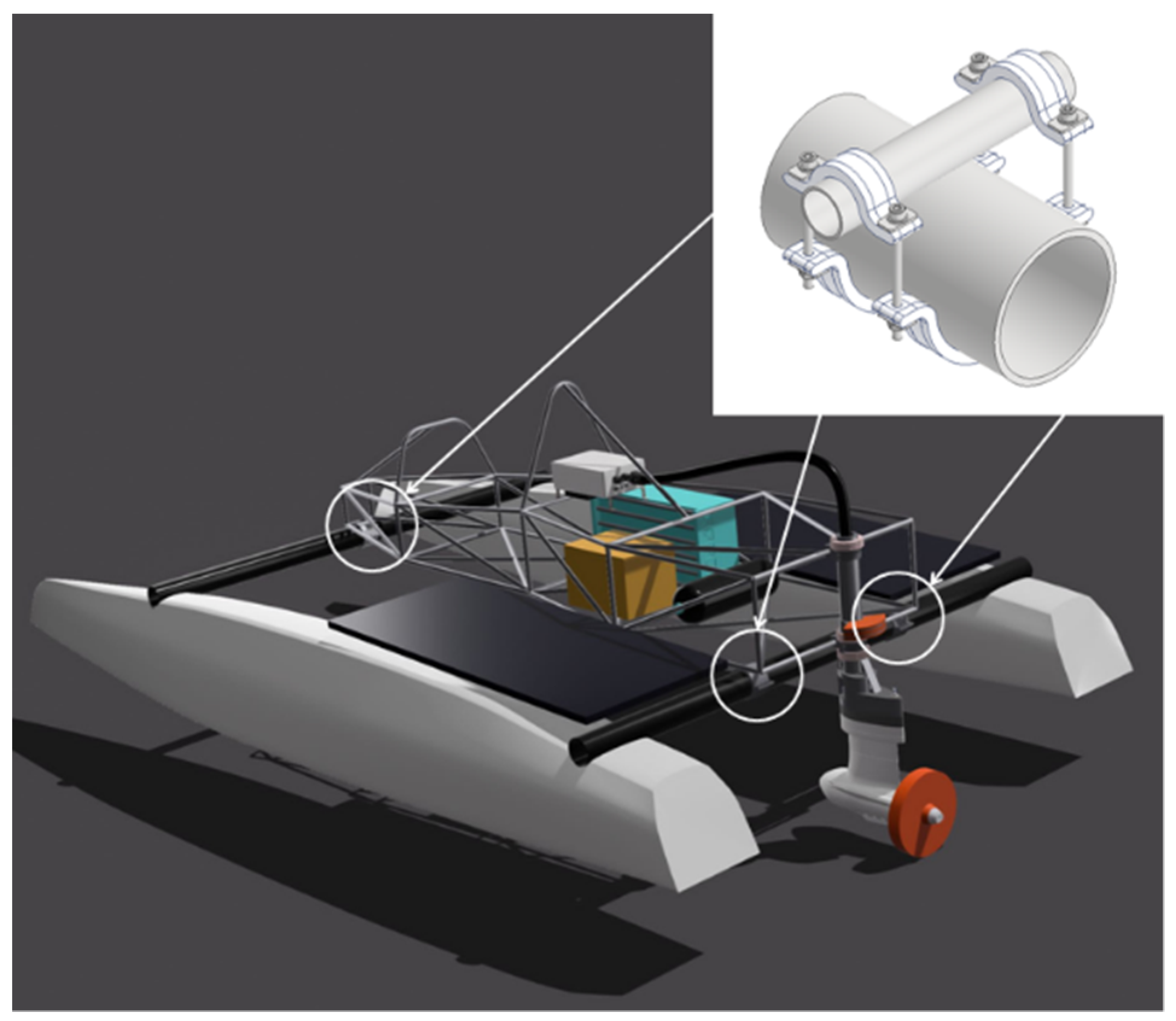
An application of additively manufactured FRP is reported in
Figure 1, where such materials and technology are applied for the construction of a “light-weight and green” structural joint for a small racing boat. In particular, such a joint is applied for the structural connections between the cockpit frame and the boat cross beams, highlighted in white. The joint is made of fibre-reinforced plastics having a low environmental impact. In particular, a PETG thermoplastic matrix is reinforced by continuous basalt fibres (CBF). The fibre reinforcement is placed through a purposely studied additive manufacturing technique, according to preferential patterns, to achieve optimal structural performances (e.g., optimal stiffness–weight ratio) that match technical specifications.
Despite the promising technology and materials, composite components produced by AM usually possess inferior and more anisotropic mechanical properties with respect to traditionally manufactured components [
11]. Moreover, such properties are highly influenced by the manufacturing strategy, which involves defining process parameters, deposition patterns, and post-processing solutions. Each strategy leads to different outcomes as it highly affects the product properties [
12]. These features directly impact the design process, which should be purposely developed to leverage the flexibility of the manufacturing process and to account for the influence of process parameters on the component’s mechanical performance [
13].
It is worth mentioning that a growing interest towards fibre-reinforced thermoplastic produced by additive manufacturing has been registered in recent years. The mechanical properties of polyamide-based composite combined with short and continuous carbon fibres have been investigated in [
14]. A multiple criteria model has been established for materials selection, considering environmental, economic, social, and physical impacts. The effects of process parameters and heat treatment on the tensile properties of 3D printing continuous carbon-fibre-reinforced PLA composites were investigated in [
15,
16], respectively. In this regard, a particularly relevant parameter to be considered is the fibre printing orientation, as it significantly influences the mechanical performances of continuous FRP. The fibre reinforcement oriented parallel to the load direction provides a significant improvement in tensile strength, while alternated reinforcement orientation (e. g. 0°–90°) achieves marginal improvements, w.r.t. matrix-only specimens [
17]. Moreover, one of the major concerns affecting the efficient use of additively manufactured composites is their weak interlaminar (or intralaminar) bonding compared with conventional pre-preg composites. Poor bonding strength may indeed effect global structural performances. The interlaminar bonding performances are marginally influenced by the thickness of the specimens, while they are moderately affected by the fibre volume content [
18]. Even though the research interest in the field has been relevant, there are currently only a few studies [
19] regarding the potential applicability of fibre-reinforced composites, produced by AM, in the maritime sector.
Considering this framework, the present study focuses on the structural performances of fibre-reinforced plastics (FRP) produced by additive manufacturing. The main objective is to evaluate their potential applicability as structural solutions for marine applications. To achieve the objective, a promising multi-material AM process has been chosen as a case study, and FRP specimens, produced by such a technology, have been analysed through a systematic testing campaign. The tensile behaviour of chopped and continuous carbon-fibre-reinforced thermoplastics has been investigated, taking into account the anisotropy induced by the additive manufacturing methodology and the influence of thermal post-manufacturing treatments (annealing) on the mechanical properties. Moreover, non-destructive techniques (e.g., optical microscopy and flash thermography) have been applied to achieve in-depth knowledge of the relation among the AM methodology, the mechanical performances, and the failure modes of the analysed materials. Test setups have been developed accounting for the requirements of the Classification Society Rules [
20]. The potential applicability of the analysed materials for marine structures has been evaluated by considering the minimum material requirements imposed by the standards and by performing a comparative analysis concerning traditional composite structures.
In a nutshell, the main novelties of the present work are the following:
The evaluation of the influence of different carbon fibre reinforcements on the mechanical response of fibre-reinforced thermoplastics, produced by additive manufacturing;
The evaluation of the influence of the deposition methodology (deposition path) on the mechanical response of fibre-reinforced thermoplastics, produced by additive manufacturing;
The evaluation of the influence of thermal post-manufacturing treatment (annealing) on the mechanical response of fibre-reinforced thermoplastics, produced by additive manufacturing;
The correlation of the mechanical performances and failure modes of fibre-reinforced thermoplastics with the additive manufacturing methodology;
The evaluation of the potential applicability of different types of carbon-fibre-reinforced thermoplastics to marine structures.
2. Materials and Methods
This section describes the methodology applied to investigate the structural performances of fibre-reinforced thermoplastics produced by additive manufacturing for marine applications.
Tensile tests have been conducted on additively manufactured FRP specimens with the following main objectives:
To analyse the influence of different reinforcement types on the tensile performances and failure modes. This is achieved by testing different sets of specimens with two types of carbon fibre reinforcements (chopped and continuous) on a thermoplastic nylon matrix;
To investigate the impact of the deposition pattern on the mechanical properties and failure modes of thermoplastic materials reinforced with different fibre types. Plenty of printing settings need to be considered to achieve an optimal deposition process (e.g., print temperature, speed, cooling rate, etc.), and each of them influences the structural behaviour of the component. However, it can be stated that once the optimal settings are developed, the deposition pattern is one of the critical parameters to be taken into account to achieve optimal structural performances;
To analyse the influence of the thermal post-manufacturing treatment (annealing) on the mechanical performances of additively manufactured FRP. This is achieved by applying an annealing treatment to a set of FRP specimens and by comparing the results with a non-annealed set;
To evaluate the potential applicability of additively manufactured FRP to marine structures. This is achieved by comparing the mechanical properties of such materials to traditionally manufactured FRP and to the minimal material structural requirements imposed by the Classification Society Rules.
The promising additive manufacturing technique applied to produce FRP specimens is briefly described in
Section 2.1. The tensile tests have been conducted using an Instron 8854 universal testing machine (Instron, Norwood, MA, USA), with a load cell of 250 kN and a maximum torque of 2 kNm. Suitable grip pressure and testing speed have been applied to the tested specimens, and the reference standard has been considered.
Optical microscopy and flash thermography have been used to gain in-depth knowledge of the relations between the additive manufacturing methodology, the mechanical performances, and the failure modes of the specimens. In particular, the following equipment has been used: Leica microsystem DVM5000 digital microscope (Leica, Wetzlar, Germany), Leica microsystem M165C stereomicroscope, and Flir systems X8400sc thermal camera (Teledyne FLIR, Wilsonville, OR, USA).
The technical specifications for chopped fibre-reinforced specimens manufacturing and testing are reported in
Section 2.2, while the ones for continuous fibre-reinforced specimens are given in
Section 2.3. The results of the tensile tests and the failure modes analysis are reported and discussed in
Section 3.
2.1. Additive Manufacturing Technique
The promising AM technique chosen as a case study is the patented Anisoprint CFC (“Continuous Fibre Co-Extrusion”) technology. The machine Composer A3, which leverages the mentioned technique, has been used to manufacture the specimens. Such a technology produces a bi-matrix fibre-reinforced composite. The main feature is the co-extrusion of a continuous fibre filament, which is pre-impregnated and cured within a thermoset matrix, with a thermoplastic filament [
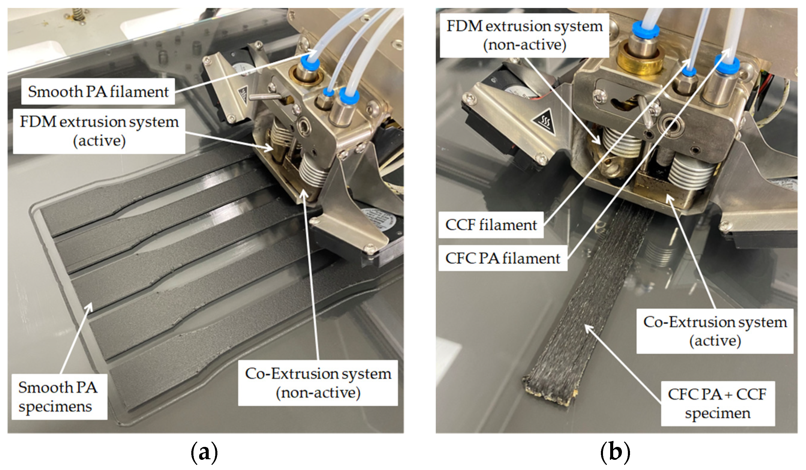
21]. The printhead is composed by two different extrusion systems. One deals with the deposition of thermoplastic materials (or chopped reinforced thermoplastics) through a classical fused deposition modelling (FDM) technique. In contrast, the other one deals with the described co-extrusion process.
All the specimens have been designed using the 3D CAD software Autodesk Inventor, while the printing profiles have been developed through the software Aura.
Figure 2 shows the deposition process of chopped and continuous FRP specimens.
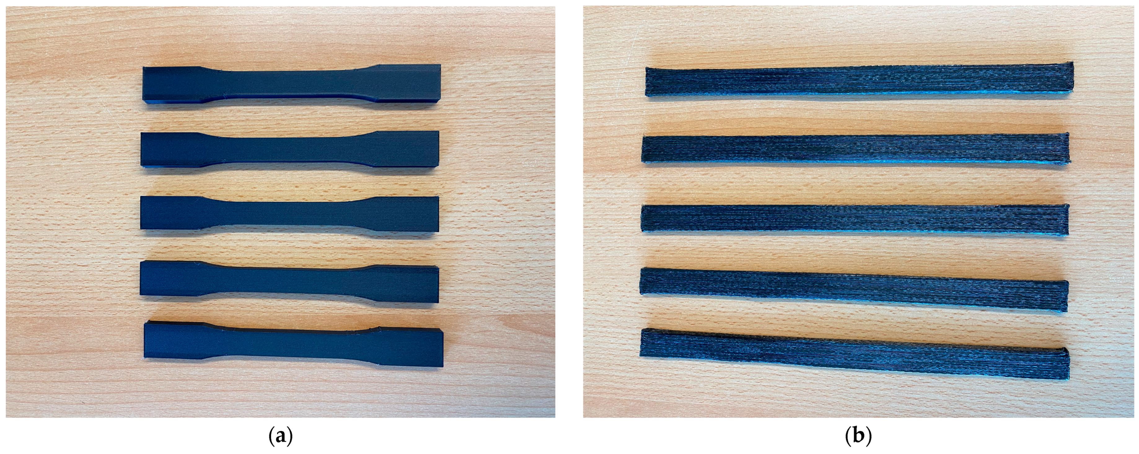
Figure 3 shows one set of additively manufactured chopped and continuous fibre-reinforced plastic specimens oriented at 0°.
All plastic filaments have been dried before printing to eliminate moisture, according to the manufacturer’s specifications. The additively manufactured specimens have been sealed in a vacuum box until testing.
2.2. Chopped Fibre-Reinforced Plastic
The used material is “Smooth PA”, a thermo-plastic nylon (PA12) reinforced by chopped carbon fibres at 10%. All specimens have been printed with a layer height of 0.2 mm, an extrusion temperature of 265 °C, and a constant speed of 40 mm/s. The used bed temperature is 60 °C, and the fan speed for cooling is 20%.
Chopped fibre-reinforced plastic specimens have been manufactured and evaluated according to ASTM D638 and concerning the test plan reported in
Table 1. The chosen standard follows the Classification Society Rules for materials manufacture, testing, and certification [
20]. The annealing treatment has been performed exposing the specimens at 80 °C for 6 hours in a drying oven, according to manufacturer specifications. Heating has been applied according to a trapezoidal profile, where the steady state is reached after approximately 15 min.
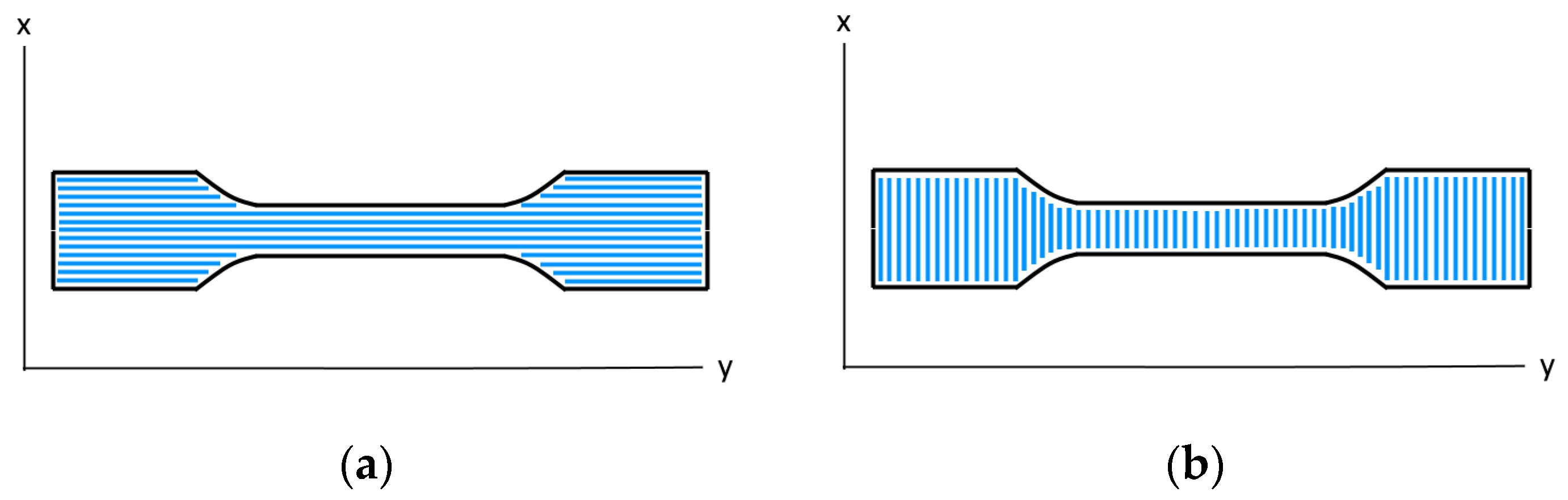
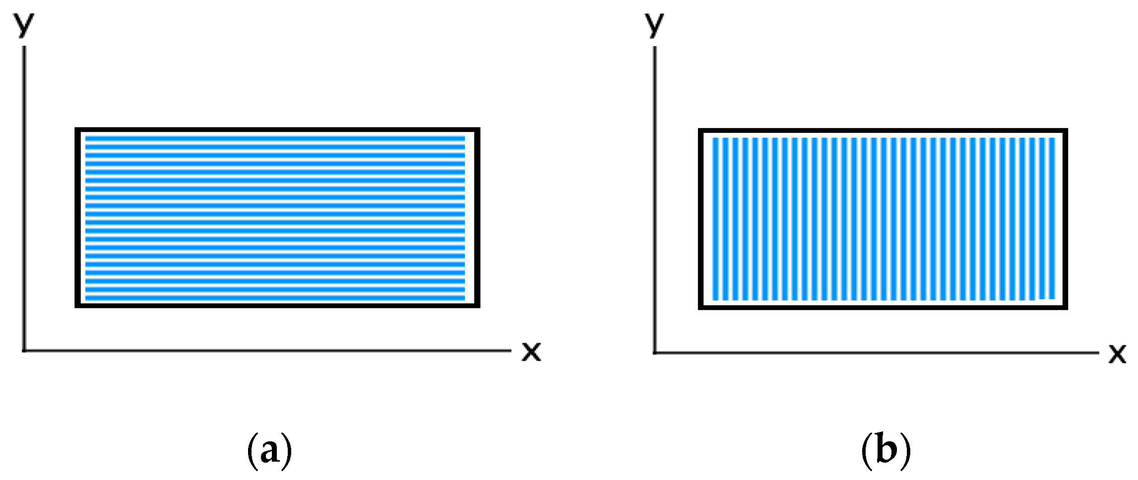
Figure 4 compares the planned deposition path for chopped fibre-reinforced plastic specimens oriented at 0° and 90°.
The specimens have been designed and manufactured according to the dimensions provided in the standard for the Type I specimen. The constant test speed is 5 mm/min, and the applied grip pressure is 5 bar. The failure modes of the specimens have been analysed using optical microscopy.
2.3. Continuous Fibre-Reinforced Plastic
The used material is “CFC PA+CCF”, a thermoplastic nylon (PA12) reinforced by continuous carbon fibre. The theoretical fibre volume fraction (FVF) is approx. 25%. All the specimens have been printed with a layer height of 0.34 mm and an extrusion temperature of 250 °C. The used bed temperature is 60 °C, and the fan speed for cooling is 50%. A fibre deposition algorithm controls the printing speed during the process, while the maximum speed is 10 mm/s.
Continuous fibre-reinforced plastic specimens have been manufactured and evaluated according to ASTM D3039 and concerning the test plan reported in
Table 2. The standard suggested by the Classification Societies (ASTM D638) has been modified to better suit the continuous reinforcement in place and for comparison purposes with specimens manufactured by different AM techniques, which have been evaluated according to the chosen standard. The annealing treatment has been performed exposing the specimens at 80 °C for 6 hours in a drying oven, according to the manufacturer’s specifications. Heating has been applied according to a trapezoidal profile, where the steady state is reached after approximately 15 min.
Figure 5 compares the planned deposition path for continuous fibre-reinforced plastic specimens oriented at 0° and 90°.
The specimens’ width and length have been designed and manufactured according to the dimensions provided in the standard, and the thickness used is 2 mm. The constant test speed is 2 mm/min, and the applied grip pressure is 30 bar. The failure modes of the specimens have been analysed using optical microscopy.
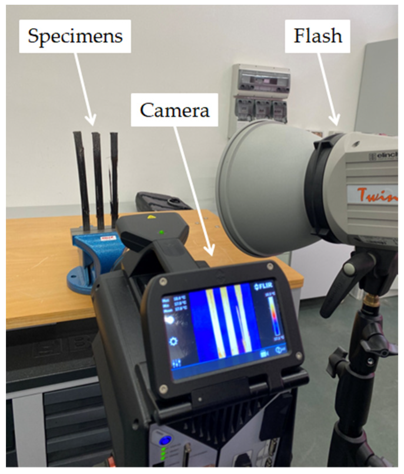
In addition, thermography has been used to highlight the preferential failure path in the specimens. The infrared camera used to perform the flash thermography tests is equipped with a cooled InSb focal plane array detector, having a spatial resolution of 1280 × 1024 pixels. The frame rate of the acquired thermograms was set to 130 Hz by sub-windowing at 640 × 720 pixels. The integration time was set at 362 μs, with a temperature range of 5 ÷ 90 °C. The lens was an MW 28 mm (38° × 31°) 2.0 HD. The camera was mounted on a tripod at a distance of 45 mm from the specimens, and the flash was placed alongside the camera.
Figure 6 shows the setup for analysing the continuous FRP specimens oriented at 0°. The thermograms were post-processed by ResearchIR Max software by applying image subtraction. The palette was the iron bow one.
3. Results
3.1. Chopped Fibre-Reinforced Plastic
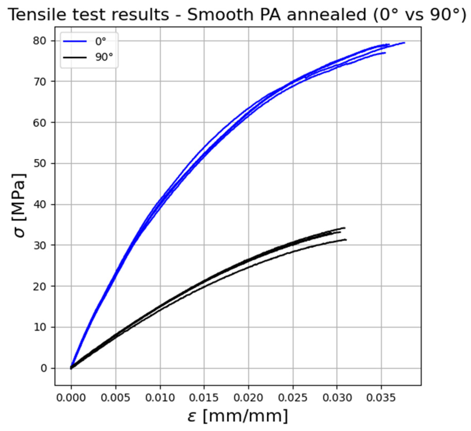
Figure 7 compares the stress–strain relationships obtained through the tensile tests on chopped FRP with different deposition patterns (0°–90°). The mean values for tensile strength (
σu), Young’s modulus (
E), deformation at the break (
), and their standard deviation are reported in
Table 3.
The deposition pattern significantly influences the tensile response of chopped FRP. In particular, the tensile strength of FRP printed at 0° orientation is more than twice the one of FRP printed at 90° orientation, while Young’s modulus is more than three times higher. The deformation at break follows the same trend, it is indeed approximately 17% higher for the FRP specimens oriented at 0°. This behaviour can be explained by analysing the extrusion process. The chopped fibres are forced to align in the deposition direction when passing through the nozzle. As the fibres exhibit higher mechanical performances when loaded in the direction of their axis, the maximum tensile properties are encountered when the deposition pattern is aligned with the load direction. The optical microscopy analysis confirms this assumption.
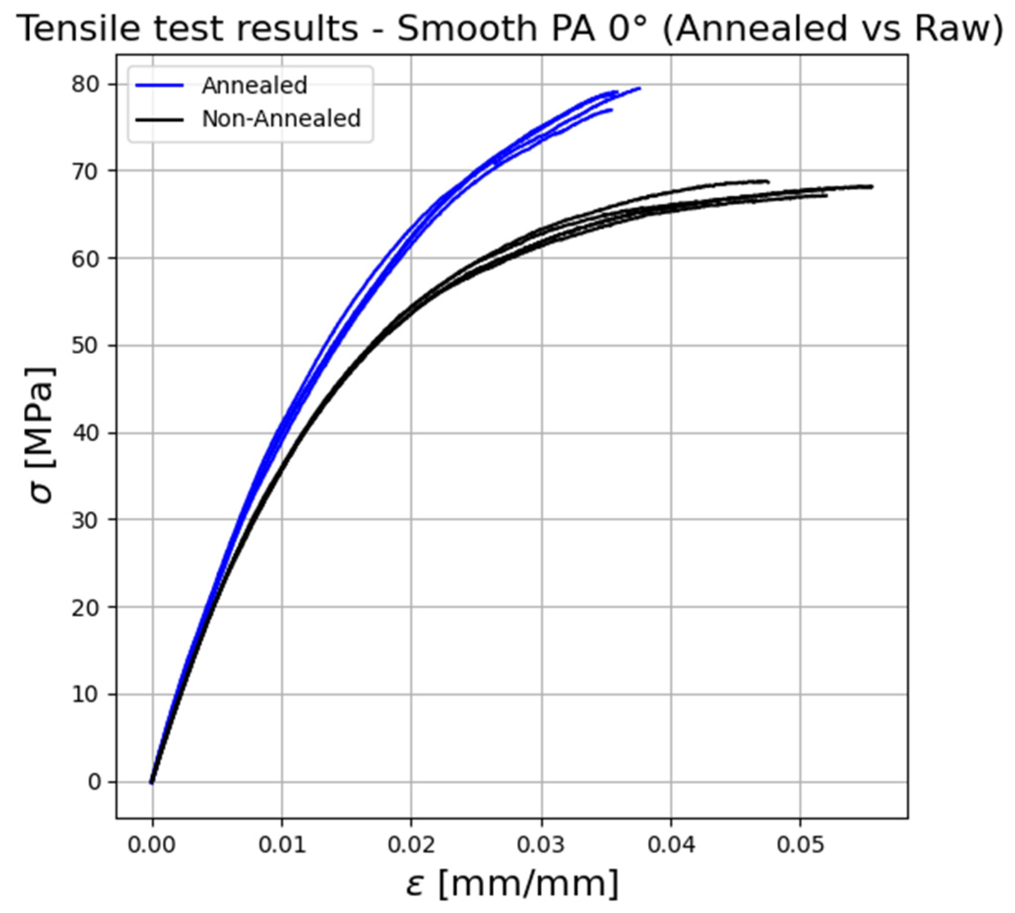
Figure 8 shows the influence of the annealing treatment on the tensile response of chopped FRP oriented at 0°.
It can be seen that the thermally treated specimens show a tensile strength and Young’s modulus which is approx. 12% higher than the one of the non-treated (raw) specimens. A reversed trend is shown for the strain at the break, which is approx. 32% higher for the raw specimens. This behaviour can be explained by the increase in crystallinity in the polymer, which leads to better inter-layer bonding and to the reduction in residual stresses and gaps between layers (porosity), caused by the material re-flow when heated above its glass transition temperature [
22].
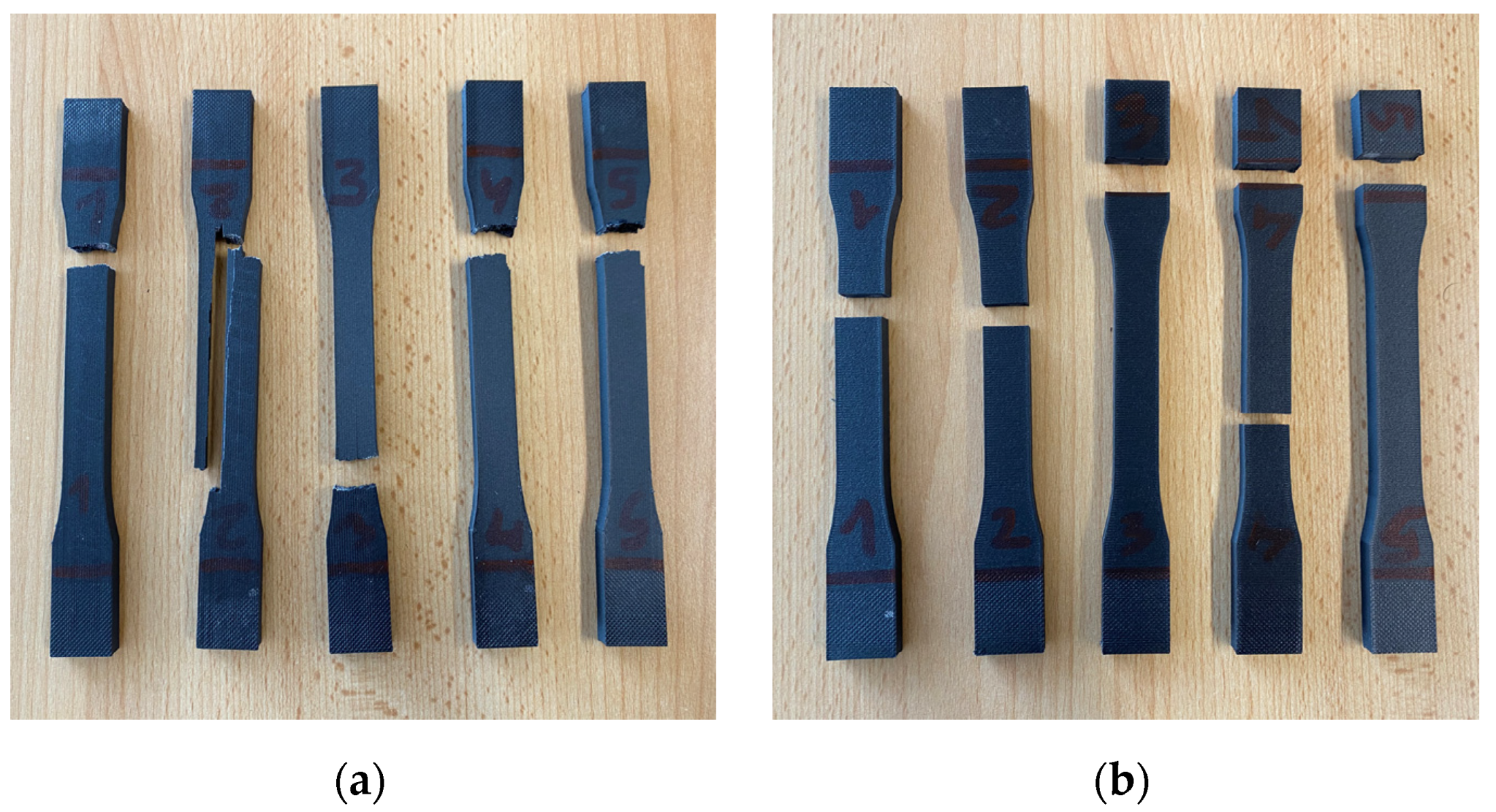
Figure 9 shows an overview of the tensile failure modes for chopped fibre-reinforced specimens oriented at 0° and 90°.
From the visual inspection of the fracture surfaces and by analysing the graphs, it can be noticed that the FRP specimens oriented at 0° show a more ductile behaviour than those oriented at 90°. The fracture surfaces of annealed chopped FRP oriented at 0° and 90°, analysed through optical microscopy, are shown in
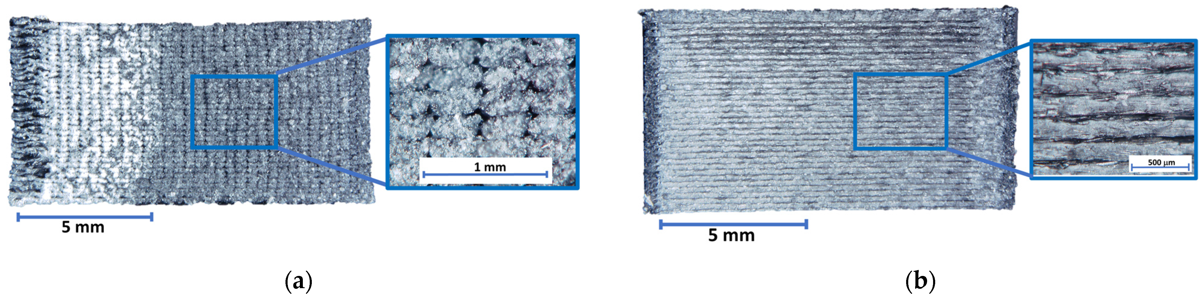
Figure 10.
It is interesting to note the layered structure of additively manufactured specimens from different observation perspectives (0°–90°). Such a structure is indeed related to the employed manufacturing method. The presence of gaps between extrusion lines is observed. Moreover, the chopped fibres (in white) alignment in the deposition direction is visible in both cases (0°–90°). As mentioned, the superior mechanical performances of the chopped FRP oriented at 0° are mainly due to the chopped fibres alignment in the load direction. For the specimens oriented at 90°, the mechanical strength relies only on the bonding among the extrusion lines, whose contact surface is reduced by the presence of gaps. In this case, lower mechanical performances are indeed encountered. Regarding the deformation behaviour, intact extrusion lines are visible on the fractured surface of chopped FRP oriented at 90°, which appears smooth and thus less deformed than the surface of the FRP specimens oriented at 0°.
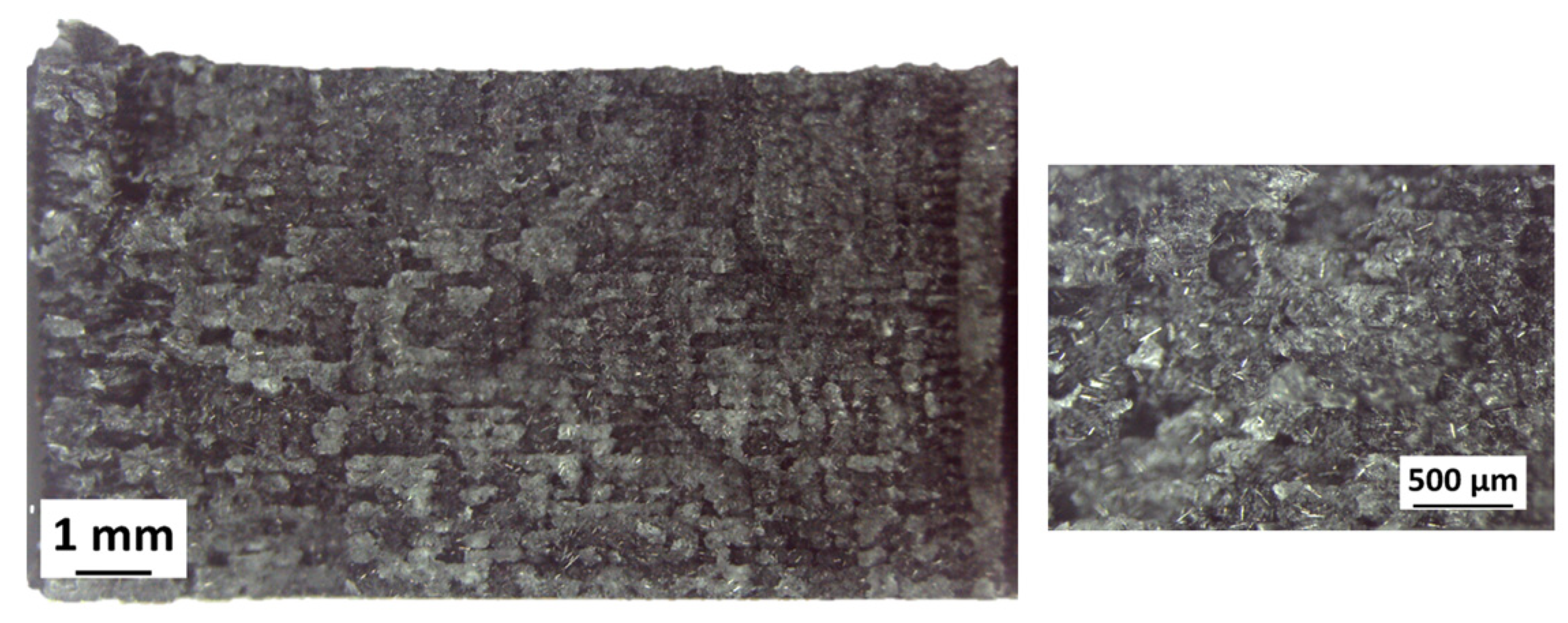
Finally, the analyses highlighted that the raw chopped FRP specimens oriented at 0° exhibit a less homogeneous structure than the annealed ones, as shown in
Figure 11.
3.2. Continuous Fibre-Reinforced Plastic
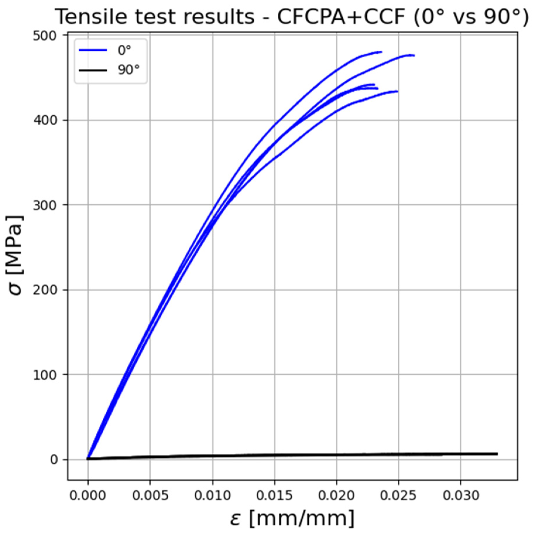
Figure 12 compares the stress–strain relationships obtained through the tensile tests carried out on continuous FRP with different deposition patterns (0°–90°). The mean values for tensile strength (
σu), Young’s modulus (
E), deformation at the break (
), and their standard deviation are reported in
Table 4.
As expected, the deposition pattern greatly influences the tensile response of continuous FRP. In particular, the tensile strength and Young’s modulus of FRP printed at 0° orientation are far higher than those of continuous FRP printed at 90° orientation, which exhibits lower properties. The deformation at break has a different trend, it is indeed approximately 22% higher for the FRP specimens oriented at 90°. Such a tensile behaviour is due to the fact that the continuous fibre does not contribute to the tensile response when it is oriented at 90° concerning the load direction. Therefore, the properties measured for the specimens oriented at 90° are related only to the pure nylon and represent the bonding strength between adjacent continuous fibre filaments (extrusion lines).
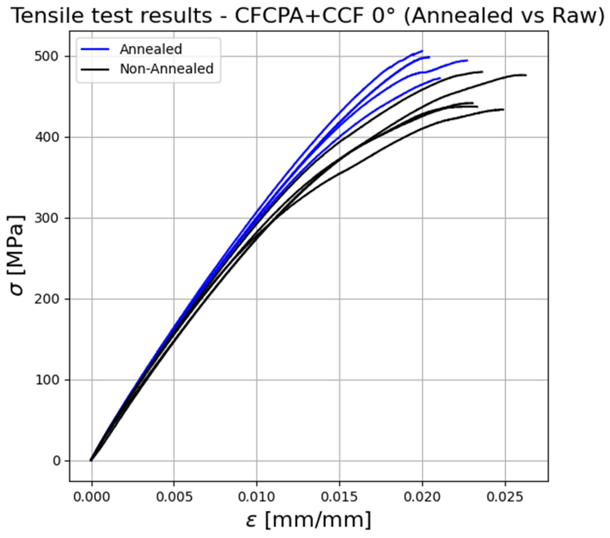
Figure 13 shows the influence of the annealing treatment on the tensile response of continuous FRP oriented at 0°.
The thermally treated specimens show a tensile strength and Young’s modulus that are approximately 8% higher than the non-treated (raw) ones. A reversed trend is shown for the strain at the break, which is approximately 14% higher for the raw specimens. These results agree with the ones obtained for chopped FRP specimens and can be related to the above-stated reasons. Such assumptions are validated by the statistical analysis, which shows that the annealing treatment lowers the standard deviations of the measured properties. This trend can be related to decreased manufacturing defects concentration in the specimens.
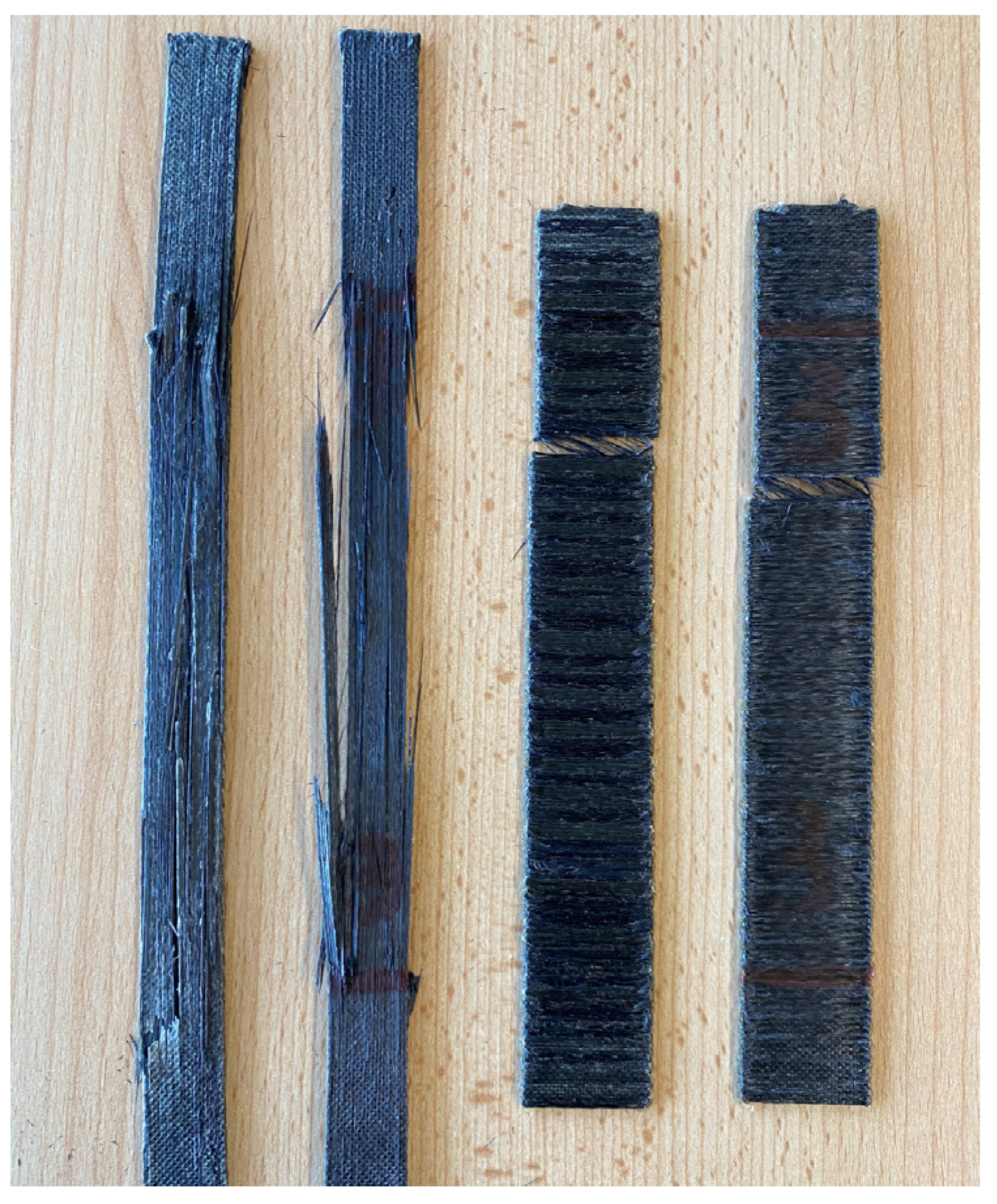
Figure 14 shows an overview of the tensile failure modes encountered for continuous fibre specimens oriented at 0° and 90°.
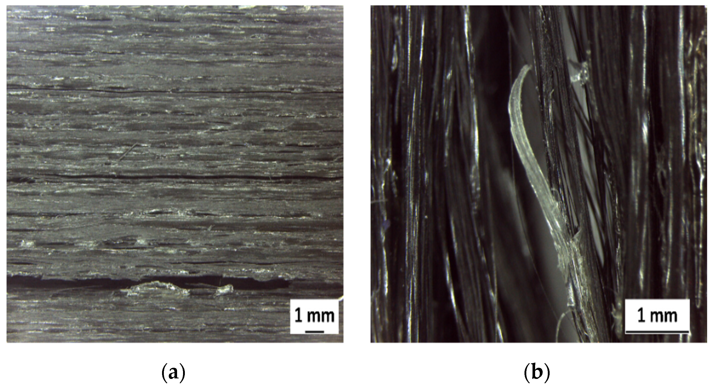
From the visual observation of the fracture surfaces of continuous FRP, both brittle fibre failure and fibre-matrix debonding can be seen. The fracture surfaces of continuous raw FRP oriented at 0° and 90°, analysed through optical microscopy, are shown in
Figure 15.
Interestingly, continuous FRP specimens oriented at 0° show preferential failure paths propagating among the extrusion lines, with brittle fibre failure and fibre-matrix debonding. Such a finding suggests low bonding strength between adjacent continuous fibre filaments. The assumption is confirmed by the deficient properties encountered for the continuous FRP specimens oriented at 90°, which may affect the matrix’s load transmission capacity, lowering the mechanical properties. The continuous FRP specimens oriented at 90° experience fibre-matrix debonding failure. The image shows the intact fibre, which separates from the thermoplastic matrix. As mentioned, the measured mechanical performances of such specimens are related to the bonding strength between adjacent continuous fibre filaments (extrusion lines).
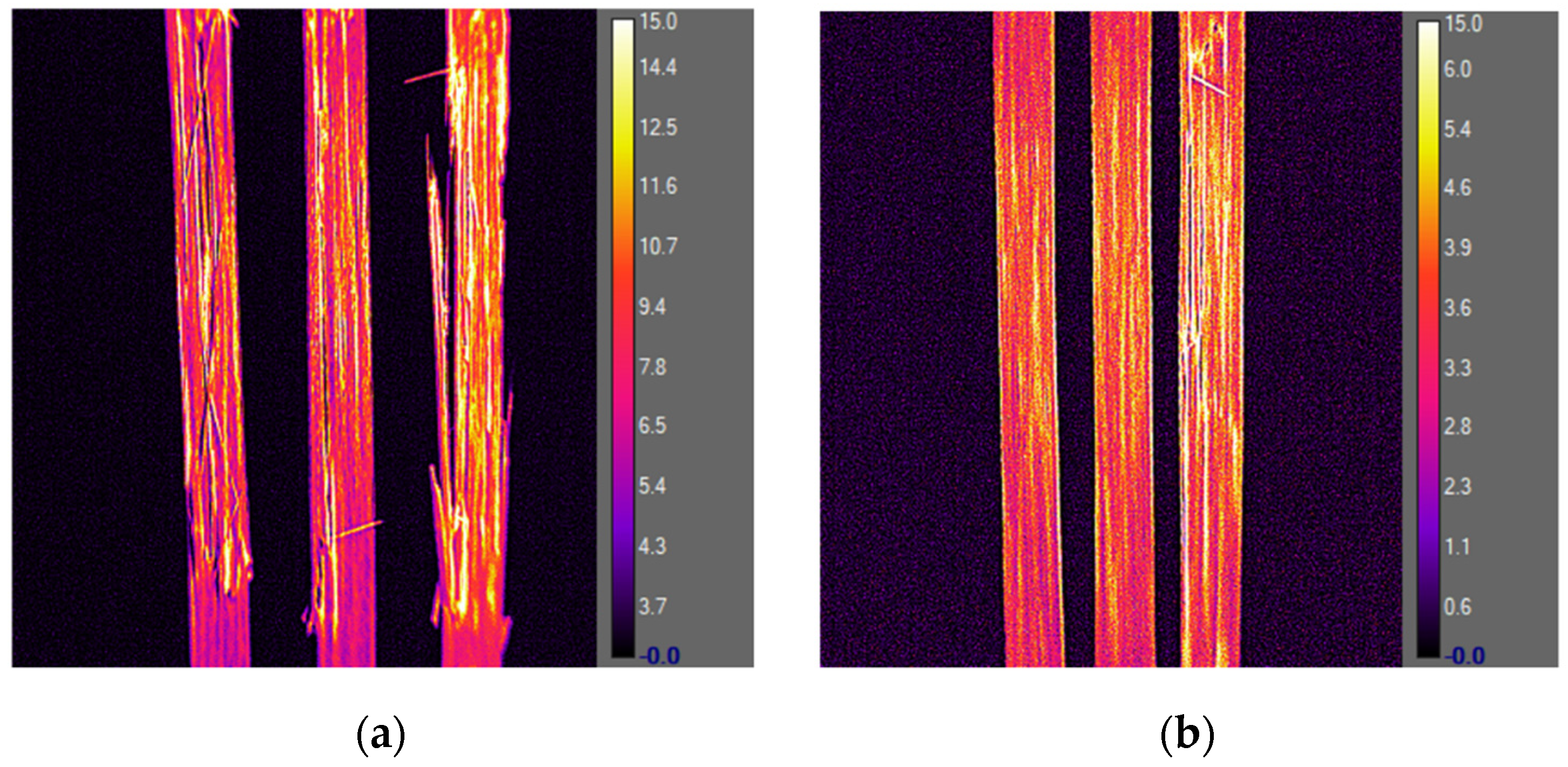
Figure 16 shows the results of the thermography analysis conducted on annealed and raw continuous FRP specimens oriented at 0°.
The analysis highlights, in a straightforward way, that the preferential failure paths are aligned with the load direction and propagate along the extrusion lines, and fibre brittle failure can also be observed. The annealed specimens show a more brittle behaviour than the raw ones. This is confirmed by the fracture surface analysis, which shows a higher fibre brittle failure concentration for such specimens. Moreover, the fracture damage is more severe for the annealed specimens, where the failure, parallel to the direction of the fibre, is associated with fibre splitting. Such a mechanism requires higher energy than the one related to the tensile failure of the matrix [
23] and may explain the higher mechanical properties encountered.
4. Discussion
The main findings of the work are given in the present section, grouped into the following categories:
Comparison of the tensile response of additively manufactured chopped and continuous FRP;
Comparison of the tensile test results obtained for additively manufactured continuous FRP with typical mechanical properties of unidirectional continuous FRP manufactured through traditional techniques;
Comparison of the additively manufactured continuous FRP mechanical properties with the minimum requirements imposed by the Classification Society Rules.
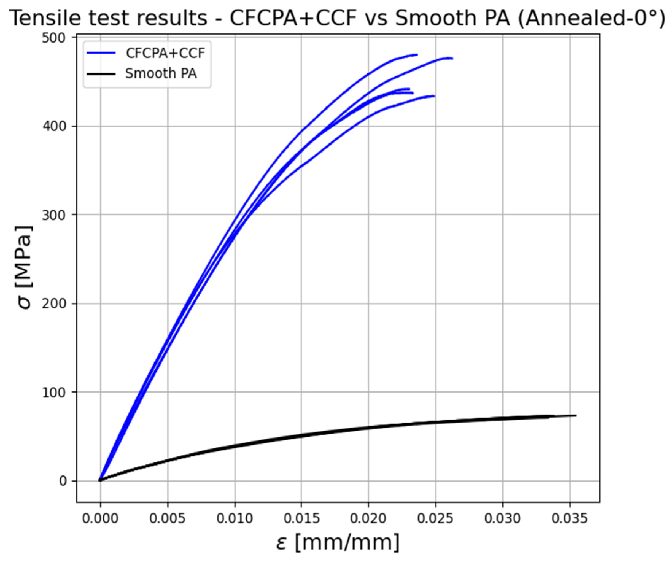
Figure 17 compares the tensile stress–strain relationships of the annealed chopped and continuous FRP oriented at 0°.
The use of the continuous fibre reinforcement leads to a significant improvement in mechanical performance. In particular, the tensile strength and modulus of continuous FRP are approximately seven times higher than the ones of chopped FRP. The strain at break shows a different trend, it is indeed approximately 40% higher for the chopped FRP specimens, showing a more ductile behaviour.
It is worth mentioning that the analysed additive manufacturing process has good repeatability. If the same specimen set is considered, this is confirmed by the low standard deviations and by the high similarity of the results.
A summary of the mechanical properties (ultimate strength and Young’s modulus) of traditionally manufactured unidirectional continuous FRP is given in
Table 5 [
24].
Comparing
Table 4 and
Table 5, it can be stated that additive manufacturing continuous FRP presents lower strength and Young’s modulus than composite structures manufactured through traditional methods. However, promising results have been achieved. In particular, the tensile strength of additively manufactured continuous FRP at 0° orientation is comparable to that of the GY-70–Epoxy. At the same time, it is twice or more times lower if other traditionally manufactured composites are considered. Young’s modulus is comparable to the glass-reinforced plastics composites (E-Glass, S-Glass), while it is twice or more times lower if other traditionally manufactured composites are considered.
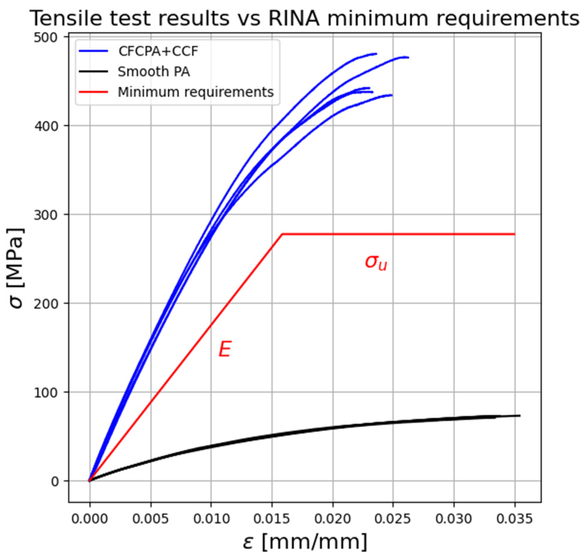
Figure 18 compares the tensile response of the additively manufactured FRP and the minimum mechanical properties requirements imposed by the Classification Society Rules [
20] for composite laminates.
The figure emphasises that the continuous carbon-fibre-reinforced thermoplastics can be a promising solution for marine structural applications. In particular, the minimum requirements on the materials’ mechanical properties imposed by the standard are matched if the continuous fibre reinforcement is employed. In contrast, the chopped fibre reinforcement leads to non-satisfying mechanical properties. The chopped carbon fibre reinforcement does not give a significant increment in strength w.r.t. matrix-only specimens, possessing modest properties in all directions. In contrast, using the continuous fibre reinforcement significantly increases component mechanical properties when the load is aligned with the fibre direction.
The minimum ultimate tensile strength and Young’s modulus have been calculated according to the Equations (1) and (2) [
20]:
The results are calculated considering a glass fraction by weight , the value that “is to be used” for manufacturing glass-reinforced unidirectional specimens for mechanical properties testing.
It is worth mentioning that the Classification Society requirement for the minimum fibre volume fraction content to be used for specimens’ mechanical testing does not match the one achievable by the additively manufactured continuous FRP, suggesting that a technological limit currently exists. The reinforcement content that “is to be used” for unidirectional carbon fibre specimen preparation is 41%, while the maximum one achievable by the considered AM technology is approximately 25%. The mentioned drawbacks relate to the raw materials used and to the additive manufacturing process. The thermoplastic–thermoset matrix lowers the global fibre volume fraction in the component and, thus, its mechanical properties. Moreover, lower properties may also be due to the absence of a compacting stage and thermal control in the manufacturing process.
5. Conclusions
The present study evaluated the tensile response of fibre-reinforced plastics (FRP) produced by additive manufacturing (AM), aiming to assess the potential applicability of such materials to marine structures. In particular, chopped and continuous carbon-fibre-reinforced thermoplastics have been investigated, taking into account the anisotropy induced by the AM methodology and the influence of thermal post-manufacturing treatments (annealing). Moreover, non-destructive testing techniques have been applied to identify the relation among the AM methodology, the mechanical performances, and the failure modes of the analysed materials. The main findings of this study are the following:
Continuous carbon-fibre-reinforced thermoplastics possess mechanical properties approximately seven times higher than chopped carbon-fibre-reinforced thermoplastics;
The additive manufacturing deposition pattern significantly influences the mechanical response. In particular, the mechanical properties are more than doubled if such a path is aligned whit the load direction. This suggests that the design process should be carefully developed to fully leverage the process flexibility and thus achieve optimal structural performances;
The annealing post-manufacturing treatment enhances the mechanical properties of approximately 10%, decreasing material ductility and manufacturing defects. Such a finding suggests that a thermal control on the AM process would benefit structural performance;
The analysis based on the Classification Society Rules related to composite materials testing suggests that there is currently a technological limit on the maximum achievable fibre volume fraction, as it does not match the one imposed by the rules for specimens’ production;
Continuous fibre-reinforced thermoplastics produced by AM match the minimum structural requirements imposed by the Classification Society Rules. Moreover, their mechanical properties are comparable to some of the traditionally manufactured composites;
The mechanical properties of additively manufactured continuous FRP are currently lower than the ones of composites manufactured with traditional methods.
The provided framework suggests that continuous fibre-reinforced thermoplastics produced by AM have a high potential to be used as light-weight structural solutions for marine applications, as far as tensile performances are concerned. However, to fully assess their potential, the full mechanical response of such materials (e.g., flexural response, interlaminar shear strength, etc.) need to be analysed, considering water absorption properties. The findings of the work suggest that the AM technology, as well as the design process, need further developments to fully achieve compliance with Classification Society Rules and structural performances comparable, or superior, to traditionally manufactured composites.


