Abstract
This paper aims to explore the current state of research on submarine cable burial machines and proposes a novel mechanical burial machine design employing a chain-type structure based on a combination of theoretical considerations and practical requirements. Through theoretical analysis, simulation, and experimental studies, the cutting process of the mechanical burial machine is investigated in detail, with special attention given to the seabed conditions in the Northeast Asia region. Starting from the dynamic process of the blade–soil interaction and the working mechanism of the blade–soil system, an accurate and reliable model for the seabed rock–soil stress is established, along with a fast computation method. A destructive analysis of rock–soil mechanical cutting is performed, elucidating the influences of the cutting depth, cutting angle, and chain blade cutting speed on cutting resistance. This paper provides reference parameters for the design of chain-type trenching devices under different seabed conditions, and adjustments are made based on simulation experiments and actual soil trenching test results. These analyses contribute practical and reliable guidance for the design and optimization of submarine cable burial machines.
1. Introduction
Submarine cable burial machines are primarily used for trenching operations on the seabed; submarine cables are buried beneath the seafloor to protect them from external forces. The origins of submarine cable burial machines can be traced back to the 1940s and 1950s, with the jetting trenching method being employed in nearshore areas. By the 1970s, as the water depths increased and excavation conditions became harsher, the development of plough-type and mechanical burial machines was prompted. In the late 1990s to the early 21st century, three main types of burial machines emerged: jetting, mechanical, and plough-type. The characteristics of these different types of submarine cable burial machines are shown in Table 1 [1,2,3,4,5].

Table 1.
Characteristics of different types of submarine cable burial machines.
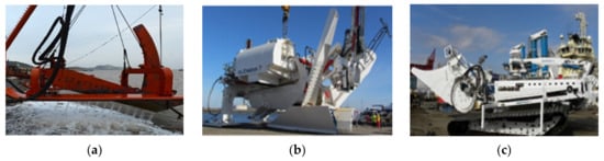
Figure 1.
Different types of seabed cable laying machines. (a) Jetting-type seabed cable laying machine. (b) Plow-type seabed cable laying machine. (c) Mechanical-type seabed cable laying machine.
Mechanical cable laying machines originated in the 1970s and witnessed the rapid development of deep-water mechanical cable laying technology and equipment in the early 21st century. These machines are primarily used for cutting through strong seabed soils such as rocks. Mechanical cutting devices like chain saws and disc cutters are employed to crush or even liquefy hard soils. Mechanical cable laying machines combine mechanical cutting with jetting or dredging, making them suitable for various seabed soil types. They overcome the limitations of jetting machines in cutting hard soils and the need for high-powered towing vessels for plough-type machines. Broadly categorized, they include chain-type, disc-type, and column-type mechanical cable laying machines based on their operational principles [6,7]. Among these, the chain-type machine is simple in structure, easy to assemble, creates stable trench profiles, and uses a multi-blade chain drive system to achieve high-speed, low-depth soil cutting. This design allows for continuous excavation at a slower pace, making it versatile for applications like laying underground drainage pipelines, telecommunications, and cable installations. It accommodates varying trench widths and depths, rendering it the most widely adopted mechanical cable laying machine today.
This paper primarily focuses on a chain-type structure submarine cable mechanical burial machine. Through a case study of the cutting process, this paper conducts a comparative analysis between the simulation results and experimental data. This study explores the impact of various cutting parameters on traction resistance, providing reference parameters for the optimization design of chain-type trenching machines under different working conditions.
2. Analysis of Mechanical Soil Cutting Mechanism
Soil cutting is the simplest and most typical soil processing method. The ultimate goal of analyzing soil cutting is to reduce traction resistance and save energy by optimizing mechanical structures and operational parameters. Research methods include physical experimentation and numerical simulation [8,9,10,11,12]. The study of soil dynamics began in the 1920s, with Soviet scholars systematically studying the plowing process of soil using mathematical methods. Nichols ML in the United States studied the operation of burial machinery, but almost all research results are based on physical experiments [13,14,15,16,17].
This paper focuses on the marine bottom sediment characteristics in the Northeast Asia sea area. Through a theoretical, simulation, and experimental analysis of the dynamic process of blade cutting soil and the blade–soil working mechanism, it establishes an accurate and reliable force model of submarine rock and soil, as well as a fast calculation method. This paper completes the destructive analysis of rock and soil mechanical cutting, determines the effects of cutting depth, cutting angle, and chain blade cutting speed on cutting resistance. Utilizing the analysis of this paper, different chain trenching parameters for different bottom sediment conditions are determined as design references in the design process of submarine cable laying machines.
The trenching process using a chain mechanism is illustrated in Figure 2. The hydraulic control system tilts the working arm of the trenching device at a certain angle. The chain blades located on the side of the tightened chain move upwards under the action of the chain. These blades then exert cutting force on the soil, resulting in soil excavation. The excavated soil, separated by the cutting teeth of the chain blades, is conveyed to the tensioning sprocket and then unloaded to both sides of the trench through a helical soil conveyor. As the trenching machine advances, the soil is removed, creating the trench. After unloading the soil, the chain blades move downward along the upper side of the trenching device frame. Once they bypass the driven sprocket, they resume cutting the soil, and this cyclic process allows for continuous excavation [18].
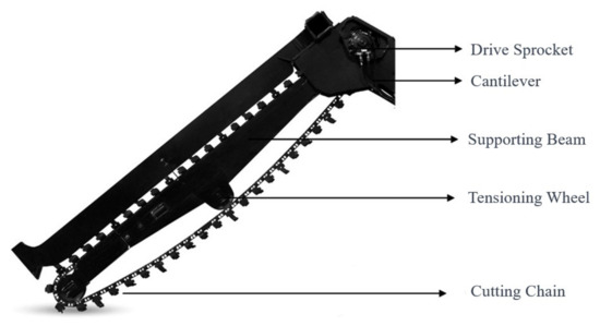
Figure 2.
Chain trenching mechanism.
The kinematic relationships are derived based on kinematic and geometric principles, as shown in Figure 3 [19].
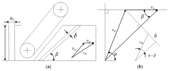
Figure 3.
Kinematic relationships. (a) Chain Blade Thickness Vector Diagram. (b) Velocity Schematic.
- is the theoretical productivity;
- is the horizontal working speed of the trenching machine;
- is the trench width;
- is the trench depth;
- is the absolute movement speed of the trenching machine chain;
- is the relative movement speed of the trenching machine chain.
is the angle between and , which is the angle between the trenching chain blade and the direction of horizontal movement. The size of angle directly affects the filling degree of the soil between the trenching chain blades. According to mechanical soil mechanics regulations [18], is generally taken between 48° and 65°, and for the trenching chain design, is chosen as 50°.
From Figure 3, the vector inclination of the absolute velocity and the expression for the chain blade cutting thickness can be obtained as follows:
where:
- is the horizontal movement speed of the trenching machine;
- is the pitch distance of the trenching chain;
- is the number of blades cutting the soil simultaneously by the trenching machine;
- is the cutting thickness. Based on existing experimental results, a reasonable cutting thickness under normal conditions is [20]
From Equation (4), we have the following:
Since in the actual trenching process, , the above equation can be simplified as
Namely, (approximately orthogonal).
The relationship between the motion speed of the trenching machine and the cutting thickness of the chain blades is shown in Figure 4.
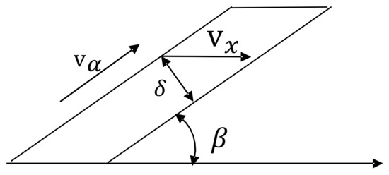
Figure 4.
The relationship between the excavation speed of the mechanical soil cutting operation and the cutting thickness.
Based on this graph, the relationship between the two can be derived as follows:
For the initially selected chain blade width and pitch, it is necessary to verify their capacity for soil conveyance and removal. The correctly chosen values should meet the following conditions [21]:
where:
- represents the actual cutting chain productivity;
- is the productivity calculated based on the chain blade’s soil-discharging capacity and the productivity for continuous operation under the “calculation conditions”;
- is the soil loosening coefficient;
- is the soil spreading coefficient related to the chain speed, as shown in Table 2.
Table 2. The coefficients of dispersion.
As the coefficient of dispersion is directly related to the chain blade’s movement speed, it is necessary to investigate the movement speed of the chain blade. During trenching, the chain blade is subjected to the driving force and soil resistance, which can lead to the wear and oscillation of the blade edge and chain link bearings. In order to ensure the quality of the operation and avoid excessive vibration, there must be certain limitations on the chain blade’s movement speed. According to the experiments in [22], the former Soviet scholars recommended a chain blade linear velocity of 1 to 2 m/s. In this paper, the mechanical cutting components are selected with a chain blade movement speed of 1.5 m/s, resulting in a corresponding soil dispersion coefficient of 0.85.
The calculation of the soil unloading capacity of the chain blade can be determined by comparing the chain’s horizontal inclination angle with the soil’s natural repose angle.
When ,
When ,
When ,
where:
- represents the height of the chain blade in the trenching mechanism;
- is the angle of natural repose.
The angle α between the absolute motion velocity of the chain trencher blade and the horizontal motion velocity of the trencher is determined based on the experimental results from the article titled “Operator and Machine Models for Dynamic Simulation of Construction Machinery”. The chain blade height is generally chosen within the range of 0.1 to 0.15 m. Considering the potential deformation and breakage of the blade when encountering obstacles at excessive heights, a smaller chain blade height is preferred while ensuring effective cutting. In this study, is selected as 10 cm; is 25 cm.
As Max(α) = 65°, the range of values for is as follows:
Substituting into Equation (10) yields
By combining Equation (9), we can obtain
According to the requirements of the trenching operations, in order to ensure that the soil cut by the blade can be smoothly carried out of the trench, it is necessary for the width of the chain blade to be ≥18.4 mm.
The thickness of the upper soil layer cut in the vertical plane along the advancing direction of the blade is referred to as the cutting depth S. The chain-type trenching machine uses the rotation of the chain to make the blades on the chain rotate and cut the soil. The cutting depth S of the chain blade can be calculated using the following equation:
where:
- represents the angular velocity of the chain axis;
- stands for the number of trenching blades simultaneously engaged in cutting the soil.
Different types of soil exhibit distinct failure mechanisms under specific conditions, and the optimal shear angle varies for different types of failure mechanisms, leading to variations in the cutting efficiency of the tools. However, based on existing research, the magnitude of cutting forces for various failure mechanisms can be calculated using the same formula. In this paper, the influence of parameters on mechanical trenching mechanisms will be studied from the perspective of cutting resistance.
During the operation of a chain-type trencher, each chain blade cuts soil into specific shapes, forming the basis for calculating excavation resistance and productivity. The shape of the cut soil chips is influenced by the structure of the trencher’s chain blade. For circular arc chain blades, the formula for calculating the cutting resistance of soil is as follows [23]:
where:
- represents the number of impacts for hardness measurement;
- is the cutting width of the trenching blade;
- is the cutting thickness of the trenching blade;
- is the influence coefficient of the cutting angle, ;
- stands for the lateral cutting quantity of the trenching blade;
- is the influence coefficient of the trenching blade’s soil processing;
- is the proportion coefficient of the trenching blade’s lateral soil cutting.
The closed-side cutting quantity of the trenching blade is determined according to the trenching blade’s working conditions. Free cutting: ; semi-closed cutting: ; and separate cutting: .
The calculated cutting resistance of a single trenching blade is
The number of trenching blades simultaneously engaged with the soil in the longitudinal direction of the arc-shaped trenching blade is denoted as in the formula.
where:
- represents the angle between the relative velocity of the trenching chain blade and the horizontal velocity of movement;
- denotes the trenching depth;
- stands for the trenching chain pitch.
The total cutting resistance of the trenching arm, , can be expressed as follows:
According to relevant studies in the literature, the total cutting power of the trenching machine is
The power consumed during the cutting and transporting of soil is
where:
- is the width between two blades;
- is the coefficient of potential soil particle clogging between the chain blade and the trench sidewall (set as 1 in this paper);
- represents the soil bulk density.
The frictional power consumption generated by the conveyed soil and the trench soil is
where is the coefficient of friction between soils.
The power consumed by the helical soil conveyor moving soil to the side of the trench is given by [24]:
where:
- is the experimentally determined soil resistance coefficient of the helical soil conveyor, typically ranging from 4 to 5 for most soils;
- is the maximum distance for moving soil along the trench edge, usually taken as 0.45 to 0.5.
The total power required for the trenching device to cut and transport soil is given by the following:
where:
- represents the chain transmission efficiency;
- denotes the efficiency of the equipment’s travel transmission.
As for the forward resistance of the burial machine, its resistance graph is illustrated in Figure 5 below:
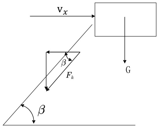
Figure 5.
Resistance diagram.
The formula for forward resistance is as follows:
where:
- G stands for the weight of the trenching machine;
- represents the coefficient of rolling resistance.
The above analysis indicates that the parameters influencing power consumption mainly include the working speed of horizontal movement of the trenching machine, denoted as , the absolute motion speed of the trenching machine’s chain cutter, denoted as , and the relative motion speed of the chain cutter to the trenching machine, denoted as .
3. Mechanical Cutting Parameter Simulation Analysis
In order to effectively analyze the mechanical performance of the mechanical trenching device in complex underwater environments, it is necessary to establish a dynamic model for the mechanical trenching and burial machine. To efficiently study the process of chain-type trencher fracturing the underwater soil under the influence of flow fields, it is essential to develop a simulation model for chain blade soil cutting under the action of the flow field. This paper employs the LS-DYNA R11.2.2 software to carry out a numerical simulation of the cutting of soil by circular arc blades. The analysis includes the examination of cutting resistance and cutting power consumption, leading to conclusions regarding the variations in the cutting speed and cutting depth.
3.1. Model Establishment
In this study, the LS-DYNA dynamic module is employed for virtual simulation analysis. The soil model is discretized using the traditional explicit dynamic method, constraints are defined, and loads are applied to the soil and blades based on actual conditions. Due to the complexity of soil cutting processes, which involve rapid changes in stress and strain, including deformation characteristics such as elasticity, plasticity, fracture, and soil failure, the numerical simulation of the cutting process assumes the following conditions:
- (1)
- During the blade cutting process, the forward speed and chain velocity are assumed to be constant, i.e., the direction and magnitude of the blade’s absolute velocity remain unchanged.
- (2)
- The soil model established in LS-DYNA has consistent stiffness and moisture content and a uniform soil structure.
- (3)
- In the cutting simulation process, it is assumed that the blade always moves within the same plane.
- (4)
- During the cutting process, the soil is assumed to remain stationary, and the combined velocity of the machine’s forward movement and chain velocity is in the direction of the blade’s motion.
To enhance the accuracy of the soil cutting simulation results, it is necessary to not only select a suitable soil model that reasonably reflects the actual situation and establish constitutive relationships that accurately represent the dynamic properties of the soil, but also to choose appropriate constitutive relationships and failure criteria for the analysis of high-speed soil cutting problems.
In this paper, the MAT147D material model of LS-DYNA is adopted. This material model employs a modified plasticity model. Table 3 shows the parameter for soil.
Table 3.
Soil parameters of clayey sand soil.
The cutting tool is a crucial factor in any mechanical trenching system. It penetrates the soil under a certain thrust and torque provided by the mechanical trenching system. The cutting tools transfer the machine’s energy to the soil, enabling the cutting process. Therefore, the geometric shape and wear characteristics of cutting tools significantly affect the energy transferred to the soil and the achievable penetration rate.
The primary target operating areas are the Northeast Asian Sea and the Zhoushan Sea, where the seabed substrate is mainly composed of cohesive soil. Based on the principle of selecting cable routes, it is essential to avoid areas with rocky seabed as much as possible. Hence, this paper selects the shape of the cutting tool as an arc-shaped trenching blade, the structure of which is illustrated in Figure 6.
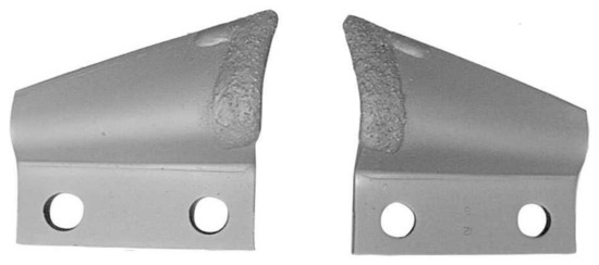
Figure 6.
Arc-shaped trenching blade.
In the simulation, the material properties of the arc-shaped cutting tool are set as shown in Table 4.
Table 4.
Material properties of circular arc cutting tool.
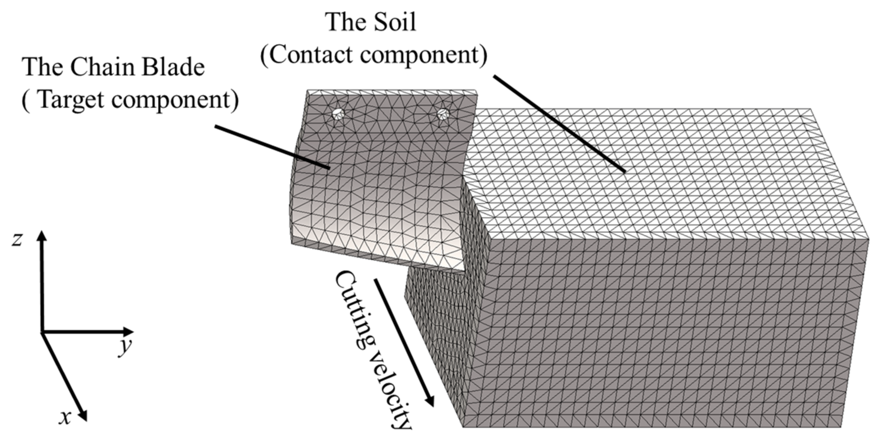
Figure 7 shows the overall grid division of the finite element model for cutting soil with a chain blade. The contact type between the chain blade and the soil is automatic single-sided contact. Moreover, the chain blade is the target component, and the soil is the contact component. In the model, the forward velocity of the blade is constant, and the direction is simplified to be perpendicular to the soil module. A specific load curve is applied to the blade node group to produce a constant velocity of motion in the x direction, with zero displacement constraints in the y and z directions.

Figure 7.
The overall mesh division.
3.2. Simulation Analysis
In the simulation study, the arc-shaped blade cuts the soil along a straight line. This section mainly analyzes the process of cutting soil by a single blade at different speeds and cutting depths. It also examines the variations in the maximum power consumption, maximum resistance, and equivalent stress during different time intervals of cutting soil at different speeds. This analysis serves as a basis for optimizing the motion and structural parameters of the cup-shaped blade.
Soil cutting is an extremely complex process with difficult-to-control variations. Extensive engineering practices and laboratory experiments have shown that soil failure is mostly due to shear failure. This is because the strength of soil particles themselves is much greater than the bonding strength between particles. Under external forces, soil particles come in contact along the direction of motion shear and slide against each other, resulting in shear failure. Due to the inherent strength of the soil, when the blade comes into contact with the soil, the cutting force on the blade does not reach the soil’s failure strength. Instead, the soil undergoes extrusion deformation under the action of the cutting force, causing the cutting force to increase. When the cutting force reaches the soil’s failure strength, the soil begins to fail, and the cutting force no longer increases but remains constant. After the entire soil block is disrupted, the cutting force decreases rapidly.
In this cutting experiment, the blade thickness is set to 6 mm, and the soil is cut laterally. Five simulation tests are conducted at speeds of 0.5 m/s, 0.7 m/s, 1 m/s, 1.2 m/s, and 1.5 m/s. The following five working conditions are proposed, as shown in Table 5.
Table 5.
Cutting conditions.
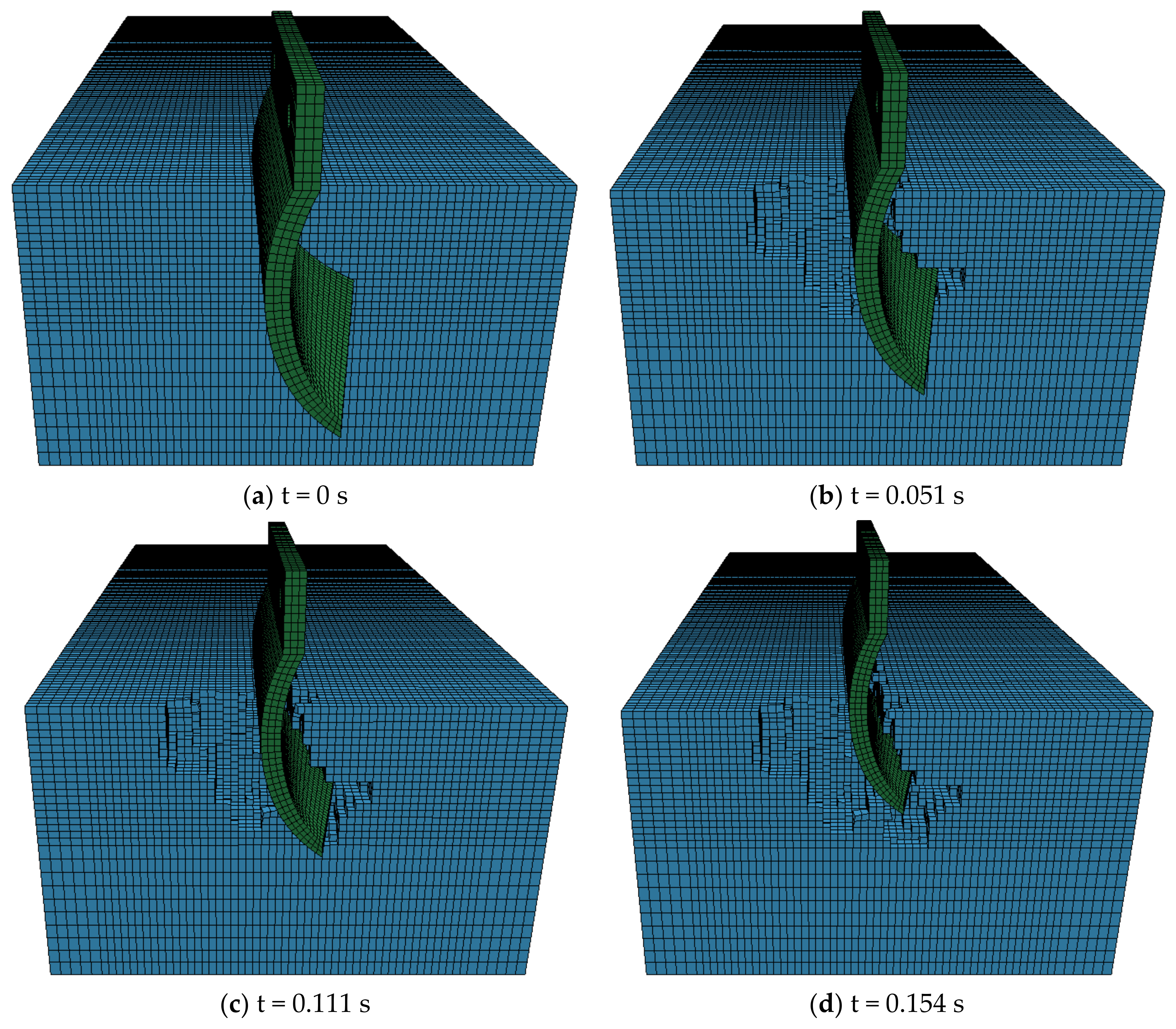
The soil cutting process by circular arc blades within one cycle is observed, as shown in Figure 8, where the initial speed of the blade is 1.2 m/s. The cutting process begins with the blade tip making contact with the soil, inducing shear failure through the cutting force. As the blade progresses, the soil experiences more intense compressive failure due to the blade’s movement. The continuous cutting action of the blade intensifies the soil disruption, and the soil ahead of the blade starts to deform under the pressure from the previously disrupted soil. Due to the compression caused by the blade, the shear strength of the soil is reduced, leading to a decrease in the cutting resistance. The soil cut by the blade is lifted, and a portion of it is thrown onto the edges of the trench, while the rest is pushed forward and to the sides by the blade’s advancing force. In the case of the chain trenching machine studied in this paper, multiple blades are simultaneously engaged in soil cutting. Through the continuous cyclic cutting action of the blades, a trench is formed.
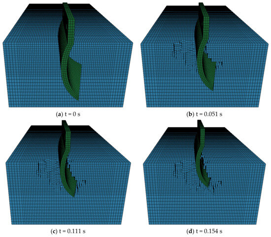
Figure 8.
Cutting conditions for cases F1-4.
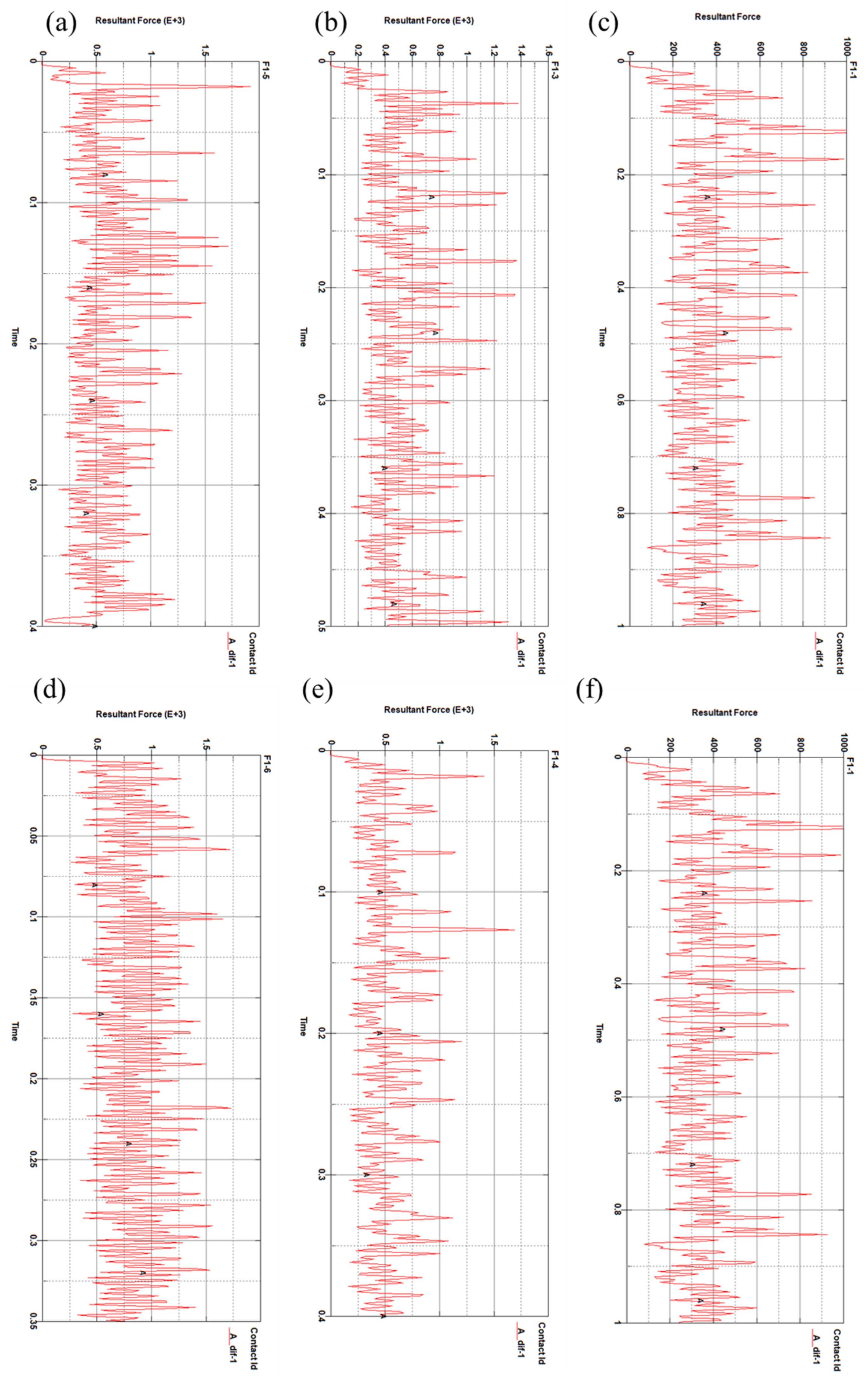
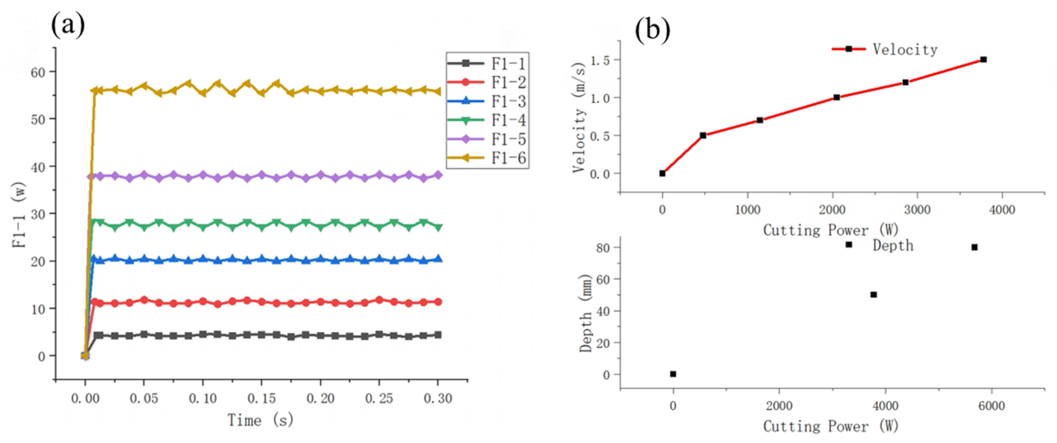
A simulation was conducted to determine the variation in the cutting force over time for the circular arc blade under these six operating conditions, as illustrated in Figure 9. In the case of Condition F1-5 shown in Figure 9e, which is similar to the parameters used in Chapter 2 for theoretical calculation, the cutting force fluctuates around 500 N, which is close to the theoretical calculated value of 462 N. It verifies the accuracy of the simulation. From Figure 9, it can be observed that in the initial stage of the trenching blade cutting through the soil, there is elastic deformation in the soil. As the contact area between the trenching blade and the soil increases, the trenching blade overcomes the elastic deformation of the soil, and the cutting force gradually increases. Subsequently, plastic deformation of the soil occurs, and the soil structure is disrupted. At this point, the force on the trenching blade fluctuates within a certain range without further increase. Comparing Figure 9a–f, it can be observed that with the increase in the cutting speed, the cutting force also increases. Through a simulation and analysis at different speeds, the reasonable selection of the cutting speed of the trenching blade under the normal operation of the trenching machine is one of the factors to reduce the cutting force.
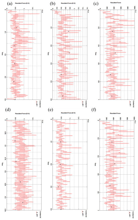
Figure 9.
Variation in cutting force. (a) In F1-1 condition. (b) In F1-2 condition. (c) In F1-3 condition. (d) In F1-4 condition. (e) In F1-5 condition. (f) In F1-6 condition.
(a) Effect of Cutting Depth
Comparing Figure 9e,f (Conditions F1-5 and F1-6), a resistance comparison chart is created, as shown in Figure 10. In the graph, Curve A represents the resistance curve for Condition F1-6, and Curve B represents the resistance curve for Condition F1-5. From Figure 10, it can be observed that with the increase in the cutting depth, the cutting force also increases. This means we can reduce the cutting speed and cutting depth to reduce the resistance. When the cutting depth has to be increased, the cutting speed can be reduced to reduce the cutting resistance.
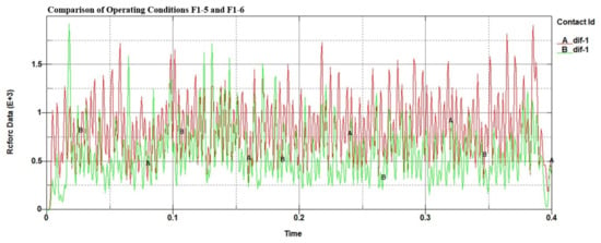
Figure 10.
Variation in cutting force for Conditions F1-5 and F1-6.
(b) Analysis of Cutting Power
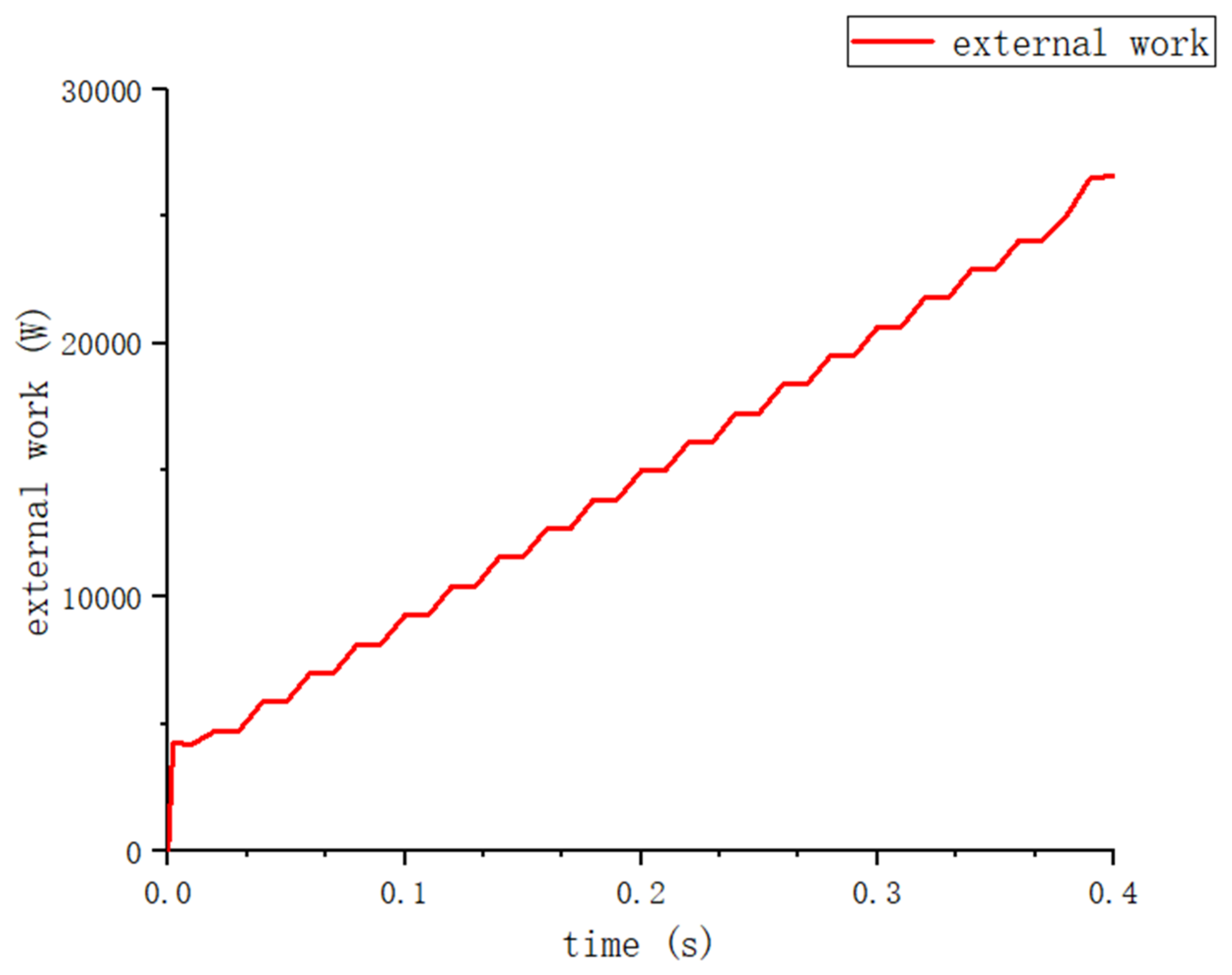
Figure 11 illustrates the variation in the cutting power for Condition F1-5 over time. From the graph, before 0.0168 s, it can be observed that in the initial stage of cutting (), there is a slow increase in the cutting power. In the stage of 0.0168 to 0.392 s, the power consumption begins to increase significantly. This may be due to the fact that the soil is compressed and deformed to crumble after the tool comes into contact with it, requiring a large amount of energy to be consumed. In the later stages (after 0.392 s), as the tool is about to exit the soil, the rate of energy increase becomes slower.

Figure 11.
Energy variation for Condition F1-5.
The differential of the power consumption curve provides the cutting power variation curve. Figure 12a depicts the changes in the cutting power over time for the circular arc blade under six different conditions. Figure 12b depicts the variation in power with the cutting speed.
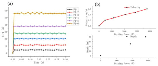
Figure 12.
Cutting power under different working conditions. (a) Power change with time with different working conditions. (b) Cutting power required for different cutting speeds and cutting depths.
(c) Effect of Cutting Speed
From Figure 12a,b, It can be observed that when the speed is less than 0.6 m/s, the cutting power increases rapidly. When the speed is greater than 0.6 m/s, the cutting speed increases linearly. Therefore, when selecting the cutting speed, there is no need to worry about the power increasing geometrically with the cutting speed. From Figure 12, it can be seen that as the cutting depth increases, there is a linear increase in the cutting power. Therefore, from the perspective of numerical simulation, the influences of speed and depth on the cutting power are similar, as they are both linear.
4. Analysis of Chain Blade Cutting Experiment
Experimental testing of chain blade soil cutting not only allows for control over the soil properties and conditions to be obtained, but also facilitates the convenient adjustment of the movement state of working components, enabling the testing of parameters such as the interaction between the trenching blade and the soil. In order to further investigate the cutting mechanism and process of the arc-shaped trenching blade, this study employs arc-shaped cutting tools and utilizes a soil trenching test method to examine the relationships between the cutting speed, cutting depth, and cutting angle of the arc-shaped tool. This experiment establishes quantitative relationships between various factors and power, constructs relevant mathematical models, and utilizes cutting resistance as the evaluation index. Building upon the virtual simulation model of blade soil cutting established in Section 3, experimental research is conducted, and a regression analysis is performed on the experimental data.
4.1. Design of Experimental Platform
In the trenching process of a chain-type mechanical trencher, the detachment of soil blocks from the ground relies primarily on the cutting action of the chain blades. Within the overall power consumption of the mechanical arm, cutting resistance accounts for a significant portion of the power consumed. The rational selection of the tool and cutting parameters can reduce the resistance of the trenching machine, decrease stress on the chain blades, enhance the operational efficiency, and serve as a key design criterion for the mechanical trenching mechanism.
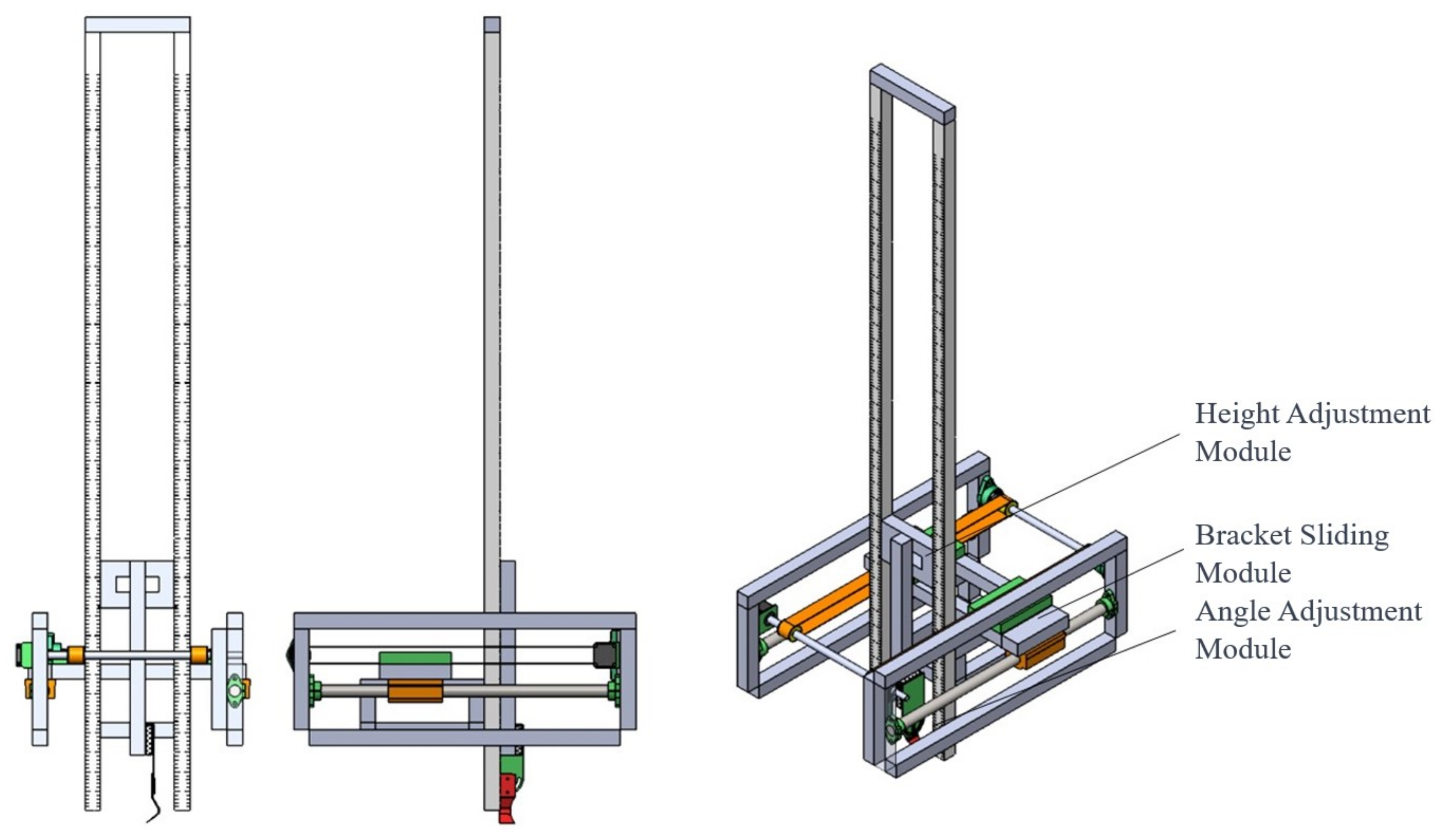
This experiment aims to identify the patterns of variation in the cutting resistance of the trenching apparatus, validate the accuracy of the simulation results, facilitate the optimization of the overall structure of the trenching apparatus, reduce the cutting resistance, and improve the machine’s operational efficiency. The main variables of the experiment include the angle of the cutting chain blade, cutting speed, cutting depth, and the influence of different cutting chain blades on the cutting resistance. The mechanical cutting test platform consists of a height adjustment module, an angle adjustment module, and a sliding guide rail platform, with its structural components shown in Figure 13.
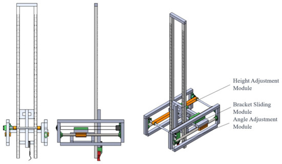
Figure 13.
Composition of the mechanical trenching platform.
(a) Cutting Angle Adjustment
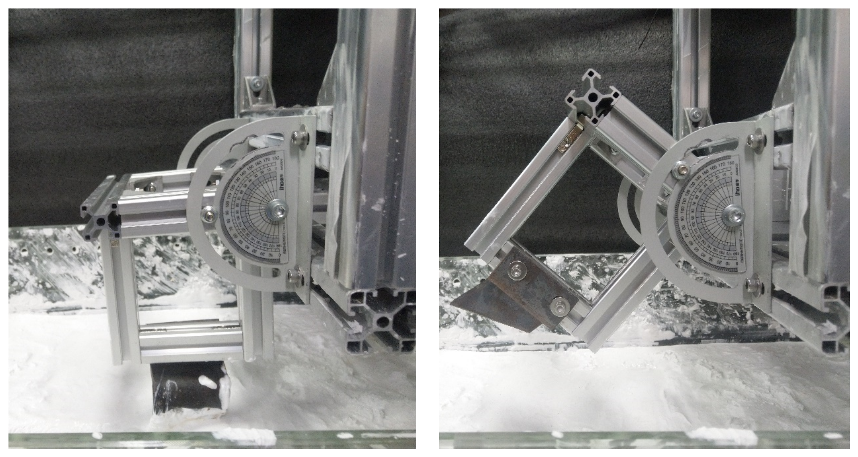
The angle adjustment module of the experimental platform is illustrated in Figure 14. The chain blade is hinged to the dial indicator through a pivot joint, and its angle is secured using aluminum profiles. The smallest scale on the dial indicator is 1°. This bracket allows for the adjustment of the cutting angle of the chain blade, with adjustment parameters set at 0°, 30°, and 45°.
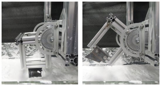
Figure 14.
Cutting angle adjustment module of the experimental platform.
(b) Height Adjustment
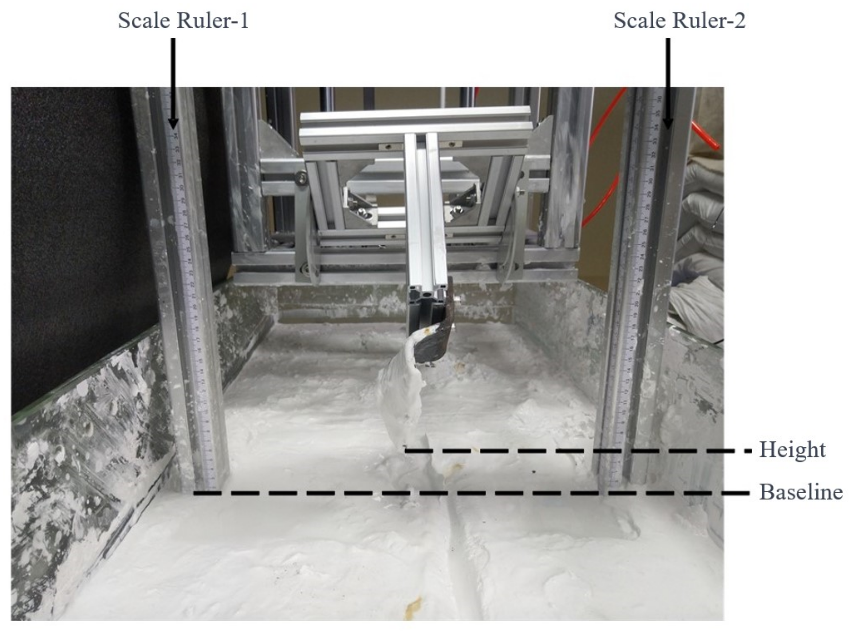
The height adjustment module is shown in Figure 15. It provides a dimension reference based on the image collected through the line diameter. During the actual jetting experiment, the bottoms of two scale rulers (at the 0 mark) always make contact with the mud surface. Meanwhile, the plane of the scale ruler is parallel to the plane of the chain blade tip. By capturing the position of the blade tip, the corresponding cutting depth can be obtained. The adjustment parameters are set at 5 cm and 10 cm.
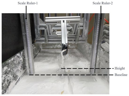
Figure 15.
Height adjustment module.
(c) Drive System
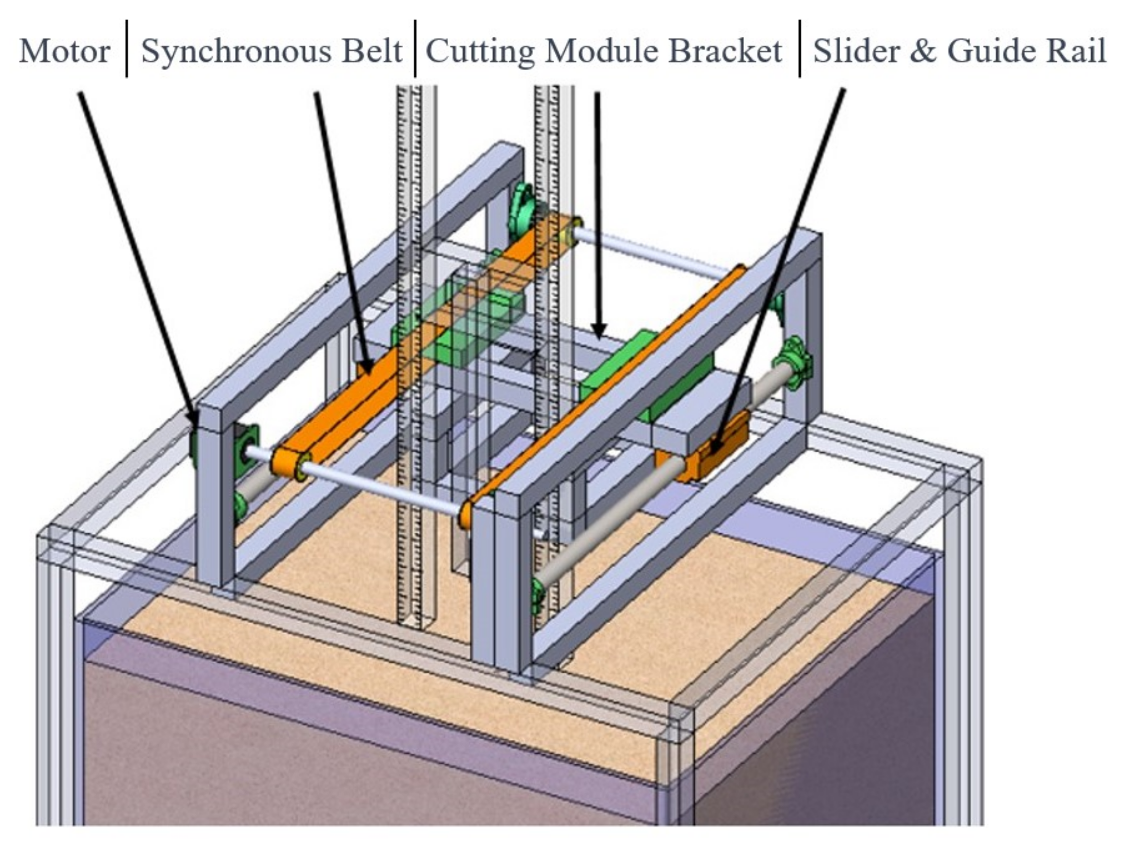
The experimental platform is constructed using 4040 aluminum profiles, as illustrated in Figure 16. This choice of aluminum profiles facilitates the assembly of the platform. The lightweight nature of aluminum profiles reduces the vibration and deflection generated on the sliding track during the experiment, while ensuring the required rigidity. The working platform is mounted on the guide rails, with a transmission device and slider installed on the upper part of the platform. This arrangement enables the platform to move along the optical axis.
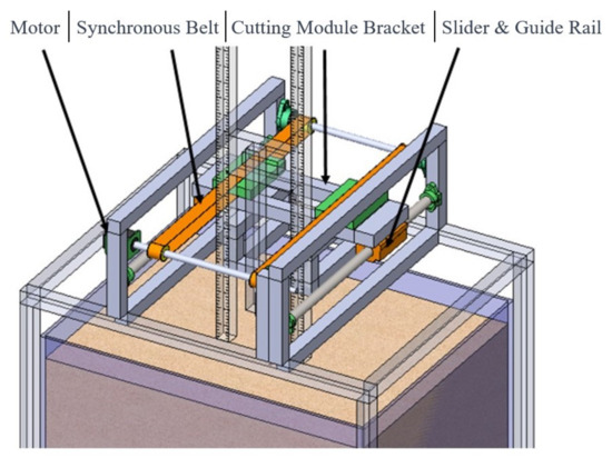
Figure 16.
Drive system.
The drive system employs a transmission configuration consisting of a stepper motor and a synchronous belt. The synchronous belt pulley is fixed to the tool holder, and the movement of the tool holder is driven through the synchronous belt pulley. The tool holder is secured to four guide rail sliders. In practical applications, the horizontal motion of the mechanical trenching operation is the same as that of the jet trenching operation. Therefore, the drive system is designed to be consistent with the equipment used in the jet trenching test platform.
The drive system employs a transmission configuration consisting of a stepper motor and a synchronous belt. The synchronous belt pulley is fixed to the nozzle holder, and the movement of the nozzle holder is driven through the synchronous belt pulley. The nozzle holder is secured to four guide rail sliders. In practical engineering, the trenching operation of the buried machine is a relatively slow process, and the driving speed must be controlled within a certain range. Meanwhile, trenching operations require overcoming significant resistance, necessitating a higher driving force. The design of the drive system is based on the selection of the motor according to the driving force and speed. The reference range for the movement speed is 30 to 70 mm/s, based on existing flushing platform speeds. The ST86 series stepper motor is chosen, which enables a platform movement speed of 0 to 118.4 mm/s.
(d) Three-Dimensional Force Sensor
In this thesis, the main purpose of the mechanical trenching test is to verify the relationship between the chain cutter cutting parameters and cutting resistance. As the chain cutter moves, it experiences spatial forces. Therefore, a three-dimensional force sensor is used in this test to measure the magnitude of the spatial forces acting on the chain cutter. The arrangement of the three-dimensional force sensor is shown in Figure 17.
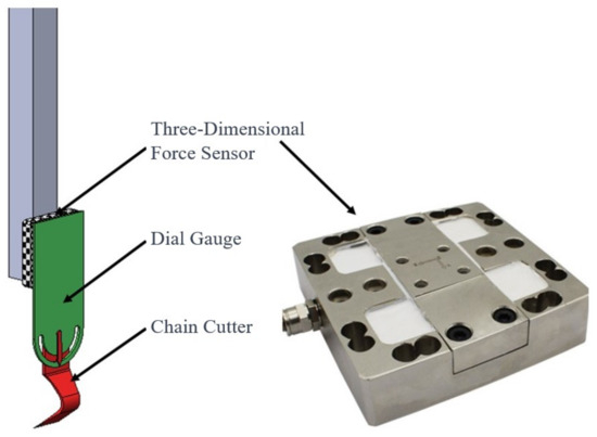
Figure 17.
Three-dimensional force sensor arrangement.
The design employs the Freud DYDW-002 three-dimensional force sensor with a range of 500 N for the XY axes and a range of 2000 N for the Z axis. The sampling sensitivity can reach 1 mV/V, equipped with a 0–5 mV analog output interface. The calibration of the sensor is required prior to the experiment.
(e) Experimental Conditions
This experiment involves a four-factor orthogonal test, with cutting tests conducted according to the designed arrangement. The experimental conditions are shown in Table 6, Table 7, Table 8 and Table 9. Each set of conditions underwent three repeated tests. Among them, the P1-1, P2-2, P3-2, and P4-1 conditions represent the same set of conditions.
Table 6.
Variable experimental conditions for cutting speed.
Table 7.
Cutting depth variable conditions.
Table 8.
Chain blade thickness variable conditions.
Table 9.
Cutting angle variable conditions.
4.2. Experimental Analysis
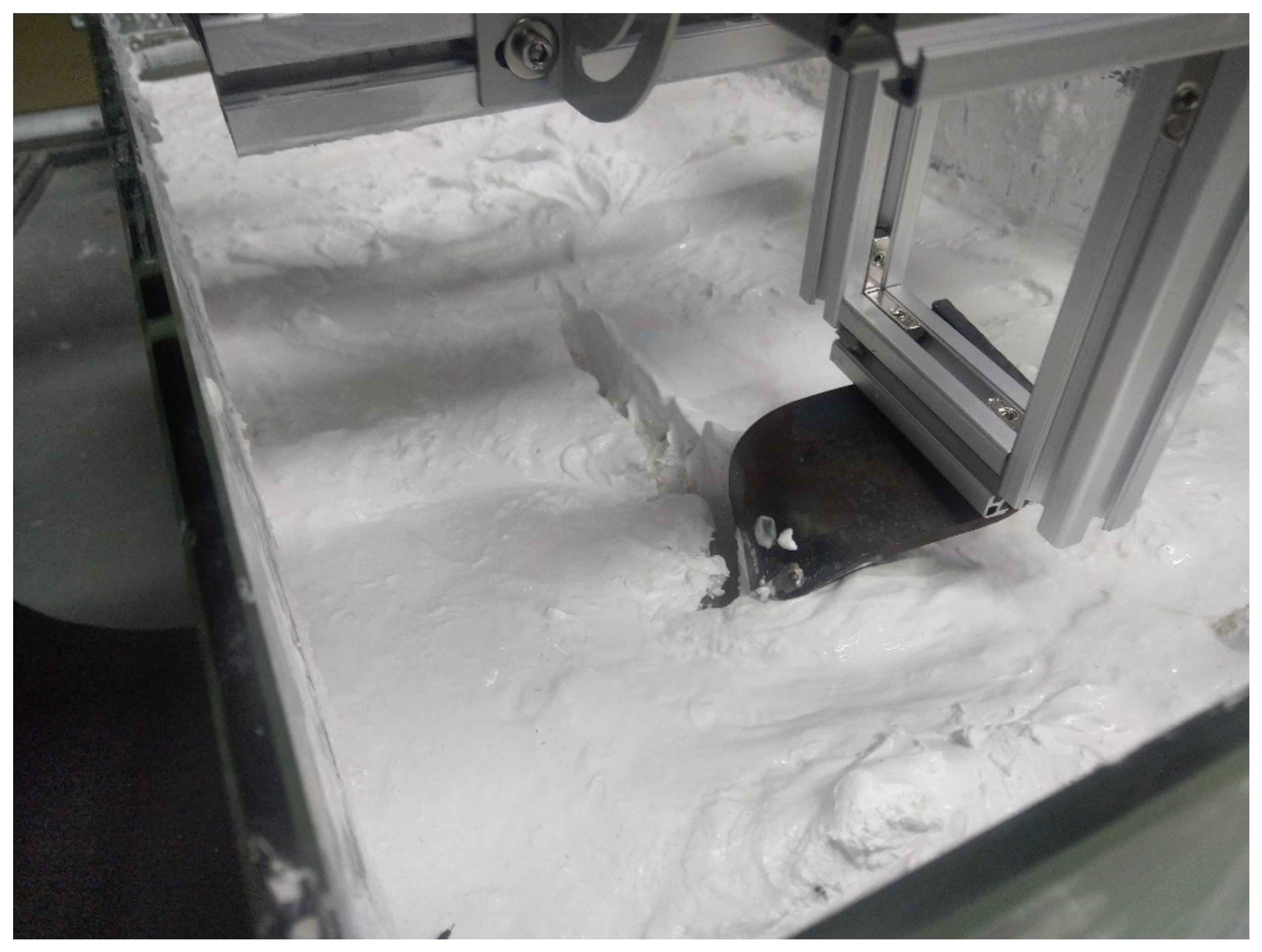
The cutting process of the circular arc trenching tool in the simulated substrate conditions during the experiment is illustrated in Figure 18.
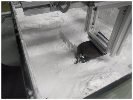
Figure 18.
Typical cutting situation of circular arc trenching tool.
To reduce errors, in this experiment, under specific conditions, the cutting resistance was repeatedly tested for various experimental conditions. The results were averaged to determine the average cutting resistance of the blade under different factors. Excluding abnormally high or low data points, the intermediate data were analyzed for the experimental results. The experimental outcomes are presented in Table 10.
Table 10.
Experimental data.
In this experiment, data analysis software was employed for experimental optimization, design, and analysis. The collected cutting resistance was used as the experimental indicator. The experimental results are presented in Table 11.
Table 11.
Experimental results analysis.
From Table 10, it can be observed that the extreme values of cutting depth, cutting speed, blade thickness, and cutting angle decrease sequentially. According to the analysis of the orthogonal experimental data results, larger values of the range R correspond to a more significant influence of the respective factors. The variation in the blade thickness has a relatively minor impact on the cutting resistance, which can be considered negligible. The primary influencing factors on the cutting resistance are identified as the cutting depth, cutting speed, and cutting angle, with the cutting depth having the most significant impact.
A comparison was made between the experimental data and theoretical calculation results in the cutting speed of 0.5 m/s and the cutting depth of 500 mm. The theoretical value is 347 N, the experimental value is 332 N (4.3% lower than the theoretical value), and the simulated value is 416 N (19.8% higher than the theoretical value). This verifies the reliability of the experimental data. Such discrepancies may arise due to various factors, such as potential deviations between experimental equipment and conditions from the intended ones.
5. Conclusions
This paper conducts a simulation analysis and experiments on the trenching chain blade of a chain-type trenching machine. This study tests the variation in traction resistance under different trenching conditions and quantifies the impacts of various cutting parameters on traction resistance. Through an analysis of orthogonal experimental data, it was determined that changes in the cutting angle have negligible effects on the cutting resistance. The primary factors influencing cutting resistance are the cutting depth, cutting speed, and blade thickness, with the cutting depth having the most significant impact.
When selecting cutting parameters for a chain-type trenching machine, it is advisable to appropriately reduce the cutting depth, cutting speed, and blade thickness to decrease the cutting resistance and enhance machine efficiency. Additionally, this paper compares and validates the feasibility of a simulation analysis, providing a viable approach for the optimization design of chain-type trenching machines.
Author Contributions
Conceptualization, Z.Y. and Z.J.; methodology, Z.Y, Z.J. and K.W.; software, C.Z.; validation, Z.Y., Z.J. and J.C.; formal analysis, J.C.; investigation, Z.Y.; resources, Z.Y.; data curation, Z.J.; writing—original draft preparation, Z.Y. and Z.J.; writing—review and editing, K.W.; visualization, Z.Y. and Z.J.; supervision, J.C.; project administration, J.C.; funding acquisition, J.C. All authors have read and agreed to the published version of the manuscript.
Funding
This research was funded by the Key Research and Development Program of Jiangsu Province, grant number BE2022062.
Institutional Review Board Statement
Not applicable.
Informed Consent Statement
Not applicable.
Data Availability Statement
Data are contained within the article.
Acknowledgments
The authors acknowledge the funding provided by the Key Research and Development Program of Jiangsu Province, grant number BE2022062. We would like to express our gratitude for the help and support given to us throughout the engineering process. We would also like to thank the reviewers for proofreading this article.
Conflicts of Interest
The authors declare no conflict of interest.
References
- Nordel, D. Nordel Annual Report 2003. 2004. Available online: https://inis.iaea.org/collection/NCLCollectionStore/_Public/36/019/36019496.pdf?r=1 (accessed on 30 November 2023).
- Song, W. Present situations and development trends of the transnational interconnected electric systems. Electr. Power Technol. Econ. 2009, 21, 62–67. [Google Scholar]
- Allan, P.G. Selecting appropriate cable burial depths-a methodology. In Proceedings of the IBC Submarine Telecommunications Conference, Cannes, France, 1 November 1998; p. 25. [Google Scholar]
- Li, X.; Chen, G.; Zhu, H.; Zhang, R. Quantitative risk assessment of submarine pipeline instability. J. Loss Prev. Process Ind. 2017, 45, 108–115. [Google Scholar] [CrossRef]
- Standard, O. Submarine Pipeline Systems. DNVOS-F101, Section H, 2000, 301. Available online: http://www.opimsoft.cn/download/reference/os-f101_2013-10.pdf (accessed on 21 October 2023).
- Griffiths, P.; Zavahir, M. Planning for New Zealands Inter-Island HVDC pole 1 replacement. CIGRE Study Committe B4 Sess. 2008, 27, 1–30. [Google Scholar]
- Zhen, Y.; Li, X.; Cao, Y.; Zhang, S. A novel method to determine critical CTOA directly by load-displacement curve. Eng. Fract. Mech. 2020, 230, 107013. [Google Scholar] [CrossRef]
- Okubo, S.; Fukui, K.; Chen, W. Expert system for applicability of tunnel boring machines in Japan. Rock Mech. Rock Eng. 2003, 36, 305–322. [Google Scholar] [CrossRef]
- Sapigni, M.; Berti, M.; Bethaz, E.; Busillo, A.; Cardone, G. TBM performance estimation using rock mass classifications. Int. J. Rock Mech. Min. Sci. 2002, 39, 771–788. [Google Scholar] [CrossRef]
- Xu, Q.; Chang, G.K. Evaluation of intelligent compaction for asphalt materials. Autom. Constr. 2013, 30, 104–112. [Google Scholar] [CrossRef]
- Hu, W.; Huang, B.; Shu, X.; Woods, M. Utilising intelligent compaction meter values to evaluate construction quality of asphalt pavement layers. Road Mater. Pavement Des. 2017, 18, 980–991. [Google Scholar] [CrossRef]
- Shuler, S.; Nobe, M.D. Edge Cracking in residential development hot mix asphalt pavements. Int. J. Constr. Educ. Res. 2007, 3, 179–197. [Google Scholar] [CrossRef]
- Barthelat, F. Biomimetics for next generation materials. Philos. Trans. R. Soc. A Math. Phys. Eng. Sci. 2007, 365, 2907–2919. [Google Scholar] [CrossRef] [PubMed]
- Bhushan, B. Biomimetics: Lessons from nature—An overview. Philos. Trans. R. Soc. A Math. Phys. Eng. Sci. 2009, 367, 1445–1486. [Google Scholar] [CrossRef] [PubMed]
- Gao, J.; Jin, Y. Soil-Cutting Simulation and Test of Oblique Rotary Tiller. In Proceedings of the Computer and Computing Technologies in Agriculture V: 5th IFIP TC 5/SIG 5.1 Conference, CCTA 2011, Beijing, China, 29–31 October 2011; Proceedings, Part III 5. Springer: Berlin/Heidelberg, Germany, 2012; pp. 140–150. [Google Scholar]
- Jiang, Z.; Jiandong, J.; Tao, J. Deep-tillage rotavator technology based on smoothed particle hydrodynamics simulation. J. Mech. Eng. 2010, 46, 63–69. [Google Scholar]
- Aluko, O.B.; Chandler, H.W. Characterisation and Modelling of Brittle Fracture in Two-dimensional Soil Cutting. Biosyst. Eng. 2004, 88, 369–381. [Google Scholar] [CrossRef]
- Chen, Y.L.; Qiu, W.; Ding, W.M.; Li, Y.N.; Liu, Y.T. Improvement and test on ditcher chain transmission system of the machine for rice-wheat cyclic planting. Appl. Mech. Mater. 2014, 644, 853–857. [Google Scholar] [CrossRef]
- Zeng, D. Mechanical Soil Dynamics; Beijing Science and Technology Press: Beijing, China, 1995. (In Chinese) [Google Scholar]
- Same Size, More Power from Newest Vermeer Rock Wheel Trencher-Utility Equipment[EB/OL]. Available online: http://www.versalifteast.com/articles/vermeertrencher.htm (accessed on 2 September 2023).
- Grant, P.; Freeman, J.S.; Vail, R.; Huck, F.P. Reparation of a Virtual Proving Ground for Construction Equipment Simulation. In Proceedings of the 1998 ASME Design Engineering Technical Conferences, Atlanta, GA, USA, 13–16 September 1998. [Google Scholar]
- Filla, R. Operator and Machine Models for Dynamic Simulation of Construction Machiner. Ph.D. Thesis, Linköpings Universitet, Linköping, Sweden, 2005. [Google Scholar]
- Gupta, S.C.; Hadas, A.; Schafer, R.L. Modeling Soil Mec hanical Behavior During Compaction. Mech. Relat. Process. Struct. Agric. Soils 1989, 172, 137–152. [Google Scholar]
- Sun, Y.; Gao, X.; Yu, D. Agricultural Soil Mechanics; Agriculture Press: Beijing, China, 1985. (In Chinese) [Google Scholar]


Disclaimer/Publisher’s Note: The statements, opinions and data contained in all publications are solely those of the individual author(s) and contributor(s) and not of MDPI and/or the editor(s). MDPI and/or the editor(s) disclaim responsibility for any injury to people or property resulting from any ideas, methods, instructions or products referred to in the content. |
© 2023 by the authors. Licensee MDPI, Basel, Switzerland. This article is an open access article distributed under the terms and conditions of the Creative Commons Attribution (CC BY) license (https://creativecommons.org/licenses/by/4.0/).