Article

Effect of Speed and Hull Length on the Hydrodynamic Performance of a Semi-Planing Hull of a Shallow-Draft Watercraft

by
Luis Daniel Leal-Ruiz
1,
Clara Paola Camargo-Díaz
1,*,
Edwin Paipa-Sanabria
1,2,
Claudia Castro-Faccetti
1 and
John E. Candelo-Becerra
3,*
1
Cotecmar, Cartagena 130001, Colombia
2
Producom, Universidad de la Costa, Barranquilla 080002, Colombia
3
Departamento de Energía Eléctrica y Automática, Facultad de Minas, Universidad Nacional de Colombia, Sede Medellín, Medellín 050041, Colombia
*
Authors to whom correspondence should be addressed.
J. Mar. Sci. Eng. 2023, 11(12), 2328; https://doi.org/10.3390/jmse11122328
Submission received: 24 October 2023 / Revised: 30 November 2023 / Accepted: 5 December 2023 / Published: 8 December 2023

Abstract

:
Hydrodynamic performance is an essential factor in the design of a watercraft, and the navigation scenario determines the complexity of its operation. This study aims to identify the effect of speed and length on the hydrodynamic behavior of a semi-planing watercraft in shallow waters. A computational fluid dynamics tool was employed to predict the trim, heave, and resistance parameters of two different hulls: a base hull and a craft with an increased hull length. The two hulls had similar hydrodynamic characteristics. The effects of speed and hull length on these predicted parameters obtained for the two hulls were compared. The results showed a low resistance uncertainty and a reduction in dynamic trim for longer hull lengths. These findings highlight the importance of considering balance and dynamic trim in designing shallow-draft watercrafts to ensure an optimal performance in specific conditions, such as rivers with depth restrictions.

1. Introduction

Worldwide, there has been a growing interest in inland waterway navigation as a strategy to reduce pollutant emissions, noise, and transportation costs [1,2,3]. The development and strengthening of river transportation is a priority in Colombia, which includes infrastructure design, financing, and improvement. Its goal is to improve the efficiency of cargo and passenger transportation, decrease emissions in the transportation industry, and enhance river safety [4,5].
Inland waterway navigation in Colombia faces challenges because of geography and changing climates. Certain types of watercrafts may face operational challenges in specific river conditions [5,6]. In shallow waters, there is a possibility that the watercraft may touch the bottom and become stranded, causing damage to the hull and compromising the safety of the crew [7].
The challenges and issues of navigating shallow waters are addressed through the design of a watercraft that can cope with depth limitations while ensuring safety and operational efficiency [8,9]. The designs should consider the hull shape, cargo distribution, and location of the center of gravity to ensure a proper draft and optimal trim. It is also essential to consider resistance and the maneuverability of the watercraft in restricted waterways [10,11]. Parameters, such as the Froude number, load distribution, and trim angle, play a fundamental role in the behavior of shallow-draft watercrafts [12,13].
In accordance with this, the Froude number is a non-dimensional factor, which is used to classify the regime of a ship hull, and is calculated using the following equation:
F r = V g L O A
where: F r —Froude number; V —Speed; g —Gravity; L O A —Length overall.
Considering the obtained result, a displacement hull is determined when the Froude number is between 0.0 and 0.4, a semi-planing hull is recognized when the Froude number is between 0.4 and 1.0, and a planing hull is identified when the Froude number is greater than 1.0 [14].
All the aforementioned parameters are essential during the hydrodynamic phase of the watercraft, where dynamic trim, weight distribution, and the position of different watercraft components are adjusted and balanced to maximize the performance in shallow waters [15]. This process significantly influences the performance and stability of the watercrafts. Changes and adjustments can be more significant for watercrafts designed for shallow waters as a lower immersion is required compared to those designed for deep-water navigation [16].
Therefore, a river reconnaissance craft (RRC) was designed, capable of navigating in depths less than half a meter to perform reconnaissance operations in hard-to-reach areas by land. This design was requested by the Colombian Navy, which required a watercraft capable of operating in shallow rivers. The design of the RRC began with the analysis of planing hulls from Series 50 [17]. The hull selection was performed by analyzing dimensional and performance factors that make them comparable for their application. This analysis obtained an initial version of the watercraft hull. Based on this analysis and with the aim of exploring strategies to reduce the draft of the watercraft, enabling its application in the design and construction of an electric watercraft subject to restricted depth conditions, various parameters were adjusted. These variations were implemented to examine how they impact the hydrodynamic performance of the watercraft and make optimal design decisions.
Previous studies on the behavior of watercrafts in shallow waters have primarily concentrated on varying different parameters of the watercraft to assess how these affect the hull performance under various conditions. Drouet et al. (2017) concentrated on optimizing the trim for the displacement of the watercraft in waves [18]. The noteworthy aspect of the study is that, by reducing the trim, they achieved a decrease in draft, resulting in a reduction of the wetted surface [18]. Additionally, Tran et al. (2022) studied the optimization strategy for planing hulls [19]. The optimization strategy focused on reducing the resistance by adjusting the location of the LCG through modifications of dimensional parameters and displacement. On the other hand, Martić et al. assessed the impact of shallow water on the total resistance of a solar catamaran through numerical simulations at different depths and speeds [20]. The results indicated a significant increase in the total resistance and sinking of the catamaran as the depth decreased at the operational speed of 5.5 knots [20]. A reduction in speed by 1.5 knots led to a notable decrease in both the total resistance and sinking [20].
Other studies that addressed this topic and employed computational fluid dynamics as a tool to analyze hydrodynamic factors include Samuel et al. [21]. In their research, they examined the hydrodynamics of a high-speed planing hull using an interceptor [21]. The study was conducted using CFD analysis, varying both the position and height of the interceptor [21]. The findings indicated that the use of the interceptor is advantageous for controlling the trim and reducing the resistance [21]. Nevertheless, they emphasized that employing interceptors at high speeds is not recommended [21]. In that context, Suneela et al. assessed the effectiveness of a numerical algorithm based on the Navier–Stokes equations to predict the behavior of a glider hull, both with and without an interceptor [22]. Their findings suggest that interceptors can reduce resistance at various wavelengths and Froude numbers [22]. Furthermore, Degiuli et al. conducted a study focused on examining the impact of the bulbous bow on the total resistance of a yacht using numerical and experimental analyses [23]. The results obtained from the computational fluid dynamics (CFD) analysis showed uncertainties below 1%, indicating the precision of this tool [23]. These findings suggest that the CFD can play a significant role in the watercraft design process [23].
Given the above, this study aims to identify how speed and hull length affect the hydrodynamic performance of a watercraft in shallow waters. For this purpose, two hulls with similar hydrodynamic characteristics were used: a base hull and a hull with an increased length of 700 mm. Subsequently, simulations were conducted using computational fluid dynamics (CFD), varying dimensional parameters of the hull to achieve the smallest possible dynamic trim during navigation at different design speeds. The CFD analysis evaluated the model of Hull No. 2743 from Series 50 (base hull) using experimental results and performance parameters of the RRC, such as the maximum draft during navigation in shallow waters, heave, trim, resistance, and speed.
The distinctive aspect of this study lies in both the methods utilized and the parameters assessed, encompassing draft, resistance, trim, and heave.
The remainder of this paper is structured as follows: Section 2 presents the verification of the model used in our study. Section 3 shows the hypotheses to reduce the case study’s draft. Section 4 provides contextual information for the selected case study. Section 5 outlines the implemented methodology. Section 6 analyzes and discusses results, and Section 7 concludes by summarizing key findings and suggesting future research directions.

2. Verification Study with Experimental Results Using Hull 2743 from Series 50

Series 50 of planing watercrafts were used to validate the computational model, explicitly referring to the reanalysis conducted by M. Morabito [17]. This reanalysis presented different hulls with modifications in the beam-to-draft ratio (B/T). The B/T ratio was compared between the RRC and the available planing hulls. Therefore, the planing hull that best matched the desired B/T ratio was 2743 from Series 50.
Figure 1 shows the computer-aided design (CAD) model for Hull 2743 from Series 50, made in Rhinoceros 7 software. This hull was modeled to perform the validation of the modelling methodology, and various parameters of Hull 2743 and the RRC were calculated. As part of this verification study, the results attained with the simulation were compared to those obtained in the experimental study performed by Morabito [17].
Table 1 shows the parameters used for the RRC and Hull 2743. The selection of the hull considered the B/T, similar to the study conducted by Morabito (2013) [17], as this parameter affects the hydrodynamic performance. The computational model was validated when the numerical predictions of hull resistance showed a maximum of a 5% difference with respect to the results of Hull 2743 obtained by Morabito (2013) [17].

3. Hypotheses for Reducing the Draft of the Case Study

The hull of the RRC was initially conceived to achieve planing. This means that operation provides Froude numbers greater than one (high speeds). The design considers the lift effects achieved during planing, as the main goal is to enable the watercraft to navigate with the lowest possible draft. For a riverine craft, navigation is constrained by the value of the hydrostatic and hydrodynamic drafts and the appendages outside the hull below the baseline, as shown in Figure 2. The term AP is Aft perpendicular, FP is forward perpendicular, WL is water line, and BL is base line.
By completing the lift on the hull, the watercraft would experience a positive displacement in the vertical axis (z-axis). This implies that a percentage of the hull would be above the waterline, resulting in a reduced draft. However, not only lift plays a significant role in the study but also the rotation of the hull around the axis transversely passing through the hull (y-axis). Negative rotation of the hull at the center of gravity of the watercraft would increase the sinking of the stern. This leads to a higher draft, which is undesirable for the intended design.
For the operation of a watercraft, the different definitions of drafts are essential in specific aspects of the mission. However, the navigation draft is undoubtedly the most significant influence when making mission-related decisions. The navigation draft and hydrodynamic draft of the hull are very similar, except for the appendage that extends downward from the hull. In some cases, this can be challenging to modify as it is a physical object that increases this dimension. However, the hydrodynamic draft results from two degrees of freedom of the rigid body, namely rotation around the y-axis and positive displacement along the z-axis.

4. Case Study

In this study, the trim and heave were taken as the main factors to reduce the hydrodynamic draft of the watercraft. The study was conducted through CFD simulations on the variation of these parameters in relation to changes in the draft. The hull length was changed to alter the longitudinal center of gravity (LCG) of the watercraft (Figure 3). This analysis helped determine the hull that has a lower hydrodynamic draft and the corresponding speed range.
The design of the RRC was based on V-shaped lines and forms, as shown in Figure 4. This figure shows a deadrise angle in the midsection of 5.42°. Unlike maritime hulls, riverine hulls often have low deadrise angles to achieve greater volume in their submerged area or below the waterline. This results in reduced submersion of the watercraft as greater buoyancy is performed in the hull.
The deadrise and flare angles are hull characteristics that contribute to the redirection of water flow during navigation. As these angles increase, they result in a greater flow separation towards the sides of the watercraft. As the design is meant for navigating in shallow waters, Figure 4 shows that these angles are not as pronounced as in a maritime watercraft. The term CL is center line and BL is base line.
The selection of the hull was determined after analyzing the results obtained from the simulations, aiming to achieve the study aim. Table 2 presents the dimensions of the original RRC. In addition, a second RRC was used with an additional 700 mm length to vary the LCG (identified in Table 2 as RRC+700). This model considers a lower trim in static or hydrostatic conditions.
Figure 5 shows the 3D model of the watercraft in its final operational form. It is a craft that optimizes space to accommodate personnel onboard because of its size and fulfills its mission. As part of the design, the watercraft was manufactured in naval-grade aluminum. In addition, it includes a control console integrating a mast, a fixed seat for the pilot, and retractable seats for passengers. It incorporates a structurally validated design using finite element analysis to achieve the best possible arrangement with the selected material and reduces the weight of the structure [9]. This design was conceived to minimize the weight of the watercraft as much as possible, thus reducing its displacement and draft.

5. Implemented Methodology

5.1. Numerical Methods

An unsteady Reynolds-averaged Navier–Stokes (URANS) solver in STAR CCM+ version 2210 from 2022 was used. The solver discretizes the governing equations using a finite volume method to model the fluid flow. Turbulence was simulated using the standard k ε   m o d e l .   T h e   s t a n d a r d   k ε turbulence model formulation were found to be reasonably robust and reliable near solid boundaries and recirculation regions, such as watercraft boundary layers [24].
The volume of fluid (VOF) model was used in the free surface of the domine with a 50% volume fraction of air and 50% water with the Eulerian multiphase model. The phases considered in this work are water as a heavy fluid and air as a light fluid. The equations used were:
Incompressible Flow:
· V = 0 , ( 1 ) ρ V t = P + μ V + · T R E + S M
where: V = Reynolds averaged velocity vector; P = Averaged pressure field; μ = Dynamic viscosity; T R E = Reynolds tenor stress; S M = Momentum source vector.
T R E   w a s   c a l c u l a t e d   u s i n g   t h e   k ε model in agreement with the Boussinesq eddy viscosity assumption.
τ i j R e = μ t V i x j + V j x i 2 3 ρ k δ i j
where: μ t = Turbulence viscosity; k = Turbulence kinetic energy.
The RANS method is correctly explained in the study from Suneela et al. [22], which considered the hydrodynamic performance of a planing hull with CFD analysis.
The computational domain height was 3.5LWL, and its width was 2LWL due to the symmetry of the problem. The domain inlet boundary was located at 1LWL ahead of the watercraft, while the outlet boundary was positioned at 3LWL from the stern of the watercraft. The dimensions of the computational domain satisfied the ITTC procedure. The recommendation was that the inlet boundary should be 1–2LPP, and the outlet boundary should be 3–5LPP away from the hull to avoid wave reflections [25]. The solver parameters are presented in Table 3.

5.2. Boundary Conditions of the Model

  • Inlet (velocity inlet): This represents the part through which the flow passes from the start (towards the bow of the hull) to the end (towards the stern of the hull—see Figure 6). Input turbulence parameters were the turbulence intensity and turbulent viscosity ratio, set at 0.01% and 10, respectively.
  • Outlet (pressure outlet): This represents the location where the flow exits the domain and is defined as a pressure outlet boundary. It represents the plane located toward the stern of the watercraft with a normal direction in the negative x-axis.
  • Side and Top (slip wall): The side and top of the domain were defined as a slip wall boundary condition, allowing the flow to move along the boundary. Therefore, the velocity at this location is not zero.
  • Bottom (no-slip wall): The bottom of the domain was defined as a no-slip wall boundary condition.
  • Symmetry Plane: Calm water conditions with no wave reflections were assumed. For this reason, it was possible to implement a symmetry plane boundary condition so that only half of the domain was simulated.
  • Vessel Wall: The watercraft is represented by a wall element that prevents the flow from passing through it and takes the shape of the craft. This allows the analysis of the fluid that passes outside of the watercraft but not the watercraft itself.
  • Free Surface: This boundary is defined as an isosurface in STAR-CCM+ where the volume fraction of air is assumed to be 0.5.

5.3. Mesh Independence Analysis

To perform the mesh independence analysis, the computational model was configured with the boundary conditions described in Section 4 at a scale of 1:7.48 or a lambda λ of 7.48. The methodology proposed in the ITTC 7.5-03-01-01 [25] was used for the verification and validation process of the mesh independence analysis. This methodology essentially seeks to find the error by comparing the real results with the estimated ones using extrapolation of Richardson. Three simulations were conducted with different mesh sizes, each time reducing the size of the base measurement of the simulation mesh by a delta difference of √2, as suggested in [25].

5.4. Initial Conditions of the Computational Model

For the configuration of the RRC and RRC+700 hull simulations, initial conditions were considered based on the working regime. In this scenario, a higher variability in transverse rotation and vertical displacement of the watercraft was observed within the computational domain, particularly at high velocities. This can cause a divergence in the result if the position and state at which the watercraft simulation starts are not equal or very close to reality. This means that at the beginning of the simulation, a trim value close to the one predicted in systematic series models, in this case Savitsky [26], was pre-established.
To obtain the initial parameters for the simulation, the Maxsurf Advanced Edition 23.03.00.101 software was used to create the geometry of the RRC and RRC+700. The data shown in Table 4 and Table 5 were obtained from these simulations.
The results obtained from this initial analysis were used as a starting point for configuring the model of Hull 2743. As it is a planing craft that will operate at high speeds, the motion of the hull must be set with specific initial trim conditions. This prevents the model from diverging in the initial seconds of simulation due to the rapid acceleration at the start, even when damping parameters, such as release and ramp time, are employed. Once the initial conditions of the computational model were determined, the model was constructed, and the mesh validation process was conducted.
After obtaining the results of the RRC, the hull length was increased to obtain the RRC+700 hull for the study. Similarly, a mesh validation process was performed for the RRC+700 hull, and the results of the systematic series using the Savitsky method are presented in Table 5.
These results influenced the initial conditions for the RRC+700 hull simulations. The parameters to initialize the simulation of the RRC and RRC+700 hulls are presented in Table 6.

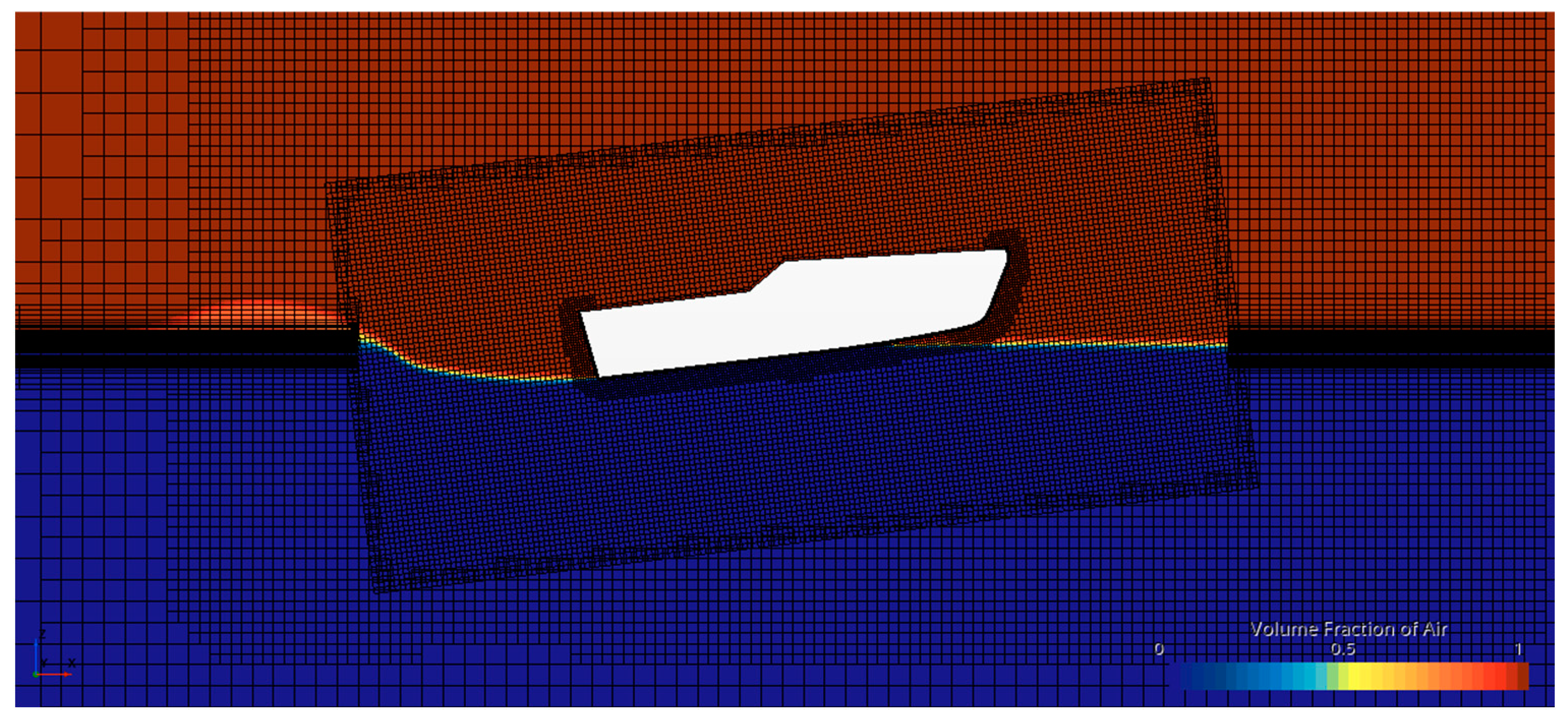
5.5. Meshing Approach

The meshing focused on solving the problems that arose from the motion of the rigid body during the simulation. Considering this aspect and previous studies, such as Niazmand et al. (2023) [27] and Suneela et al. (2022) [28], an overset region was used for the area near the hull. An automatic meshing domain was used for the fluid area farther from the hull (See Figure 7).
The meshing was configured using a base cell size, and any further changes were made concerning this “Base Size” to achieve reasonably smooth transitions. For modeling the boundary layer, a Courant number of one was used [29]. This resulted in a boundary layer thickness size of 0.3 mm for the model, with ten boundary layers only up to the hull of the watercraft. For the hull deck, two layers were modeled, maintaining the same boundary layer thickness to reduce the meshing, which was not interesting for this analysis. Finally, the simulations had a mesh volume of 1.6 to 2 million cells, which self-adjusted with the help of an adaptive meshing model available in the Star CCM+ software version 2210.

6. Results

The results presented below are part of the findings obtained from the simulations of the RRC and RRC+700.

6.1. Verification of Study Results

The type of convergence of the simulation was classified with the data of the total resistance to advance, which was obtained from the three simulations. The differences between the resistance values of the low mesh (1), medium mesh (2), and fine mesh (3) were estimated, obtaining ε 21   a n d   ε 32 . Then, the calculation of the size difference of the base for the three simulations was carried out. Finally, the equations were applied to estimate the convergence ratio, the Richardson extrapolation, the order of magnitude, and the uncertainty of the numerical simulation.
The resistance results of the simulation of Hull No. 2743 were obtained for a speed of 5.58 kn and were compared with the result of the simulation of the RRC hull at the same speed, obtaining a difference of 3.175% as shown in Table 7.
Based on the results obtained from Table 7 and considering lower differences than those presented in the validations of works, such as [30,31], the computational model used in Hull No. 2743 was established as valid and was used for the case study.

6.2. Mesh Independence Analysis Results

Table 8 presents the three possible convergence conditions, and Table 9 presents the results of the mesh independence analysis.
The uncertainty and error estimation guidelines of the ITTC [25] were considered as part of the mesh independence study. Table 10 presents the results of the numerical error calculation based on the difference in total resistance results among three simulations with different meshes (see Table 9). Here, ∆x represents the size of the base element in the control volumes of the computational model, and ri represents the mesh refinement ratio. Additionally, ε21 denotes the difference between results from the medium and low mesh simulations, and ε23 represents the difference between results from the fine and medium mesh simulations. Furthermore, Ri indicates the convergence ratio, and δRE stands for the error.
The mesh validation result was determined using the parameter Ri, with the convergence conditions i, ii, and iii defined in Table 8. After stabilizing the three simulations, the results showed an order of accuracy “pi” above the expected maximum value of p1 = 2.4. Therefore, pi is adjusted to obtain the value of the numerical simulation uncertainty [25].
Figure 8 shows the variation of the waterline length of the hull at three velocities. The relationship described in the works of Savitsky [26] and Nagai and Yoshida [32] can be observed in this result. This relationship relates L K to the variation in the trim and demonstrates that the computational model exhibits a consistent behavior with the governing physics.
On the other hand, in Figure 8, the differences in flow can be observed from low speeds to speeds closer to the planing regime. At low rates, a more continuous and uniform flow along the length of the hull can be seen from the bow to the stern. However, in the image, at 12 knots, the flow began to separate at the bow while remaining constant along the hull. Finally, at 15 knots, a clear flow separation was evident at the sides of the hull, forming a small, turbulent zone aft, leaving only water flow along the bottom of the hull. This generated a higher lift effect at the bow, resulting in a greater stern trim.

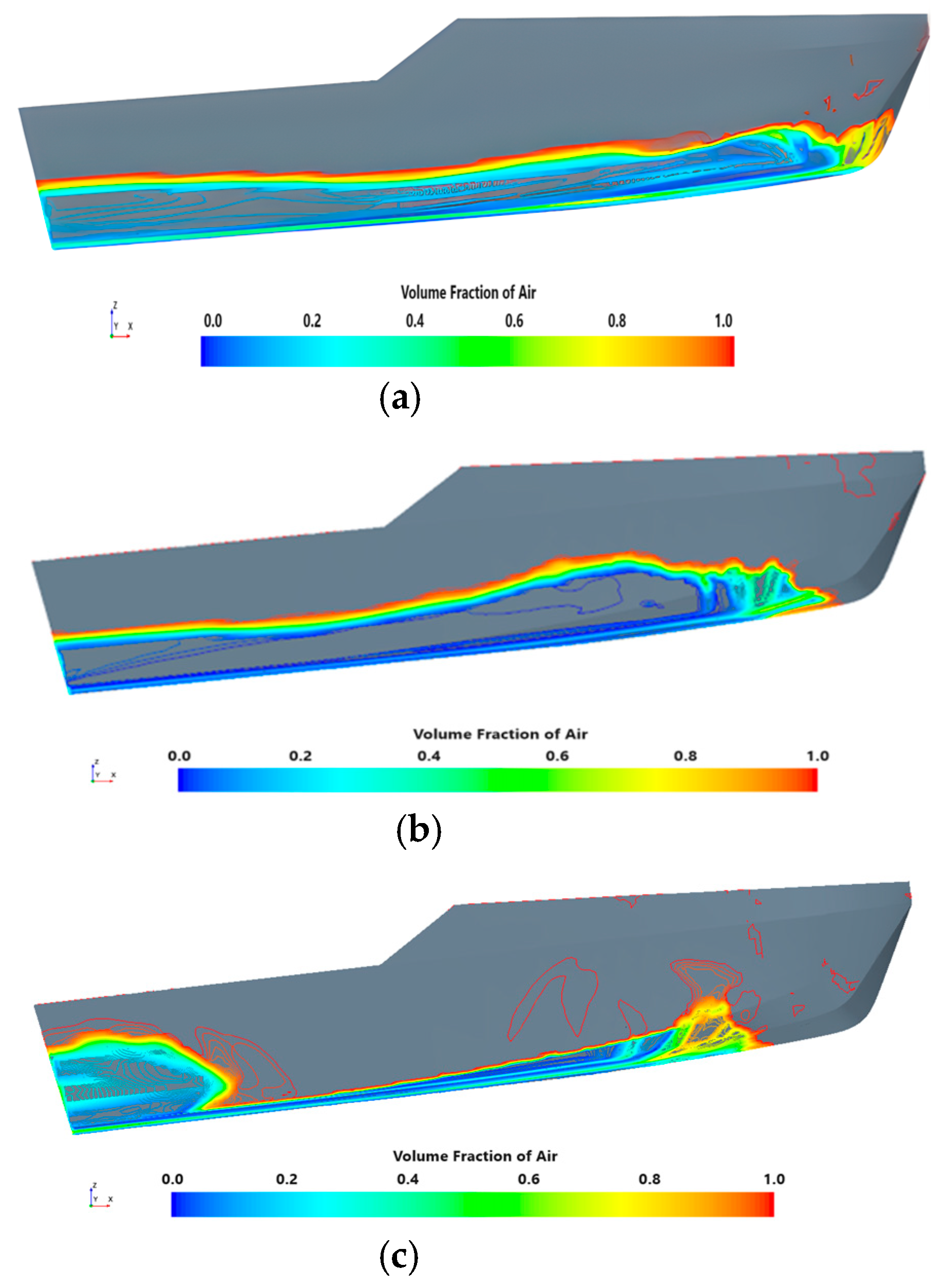
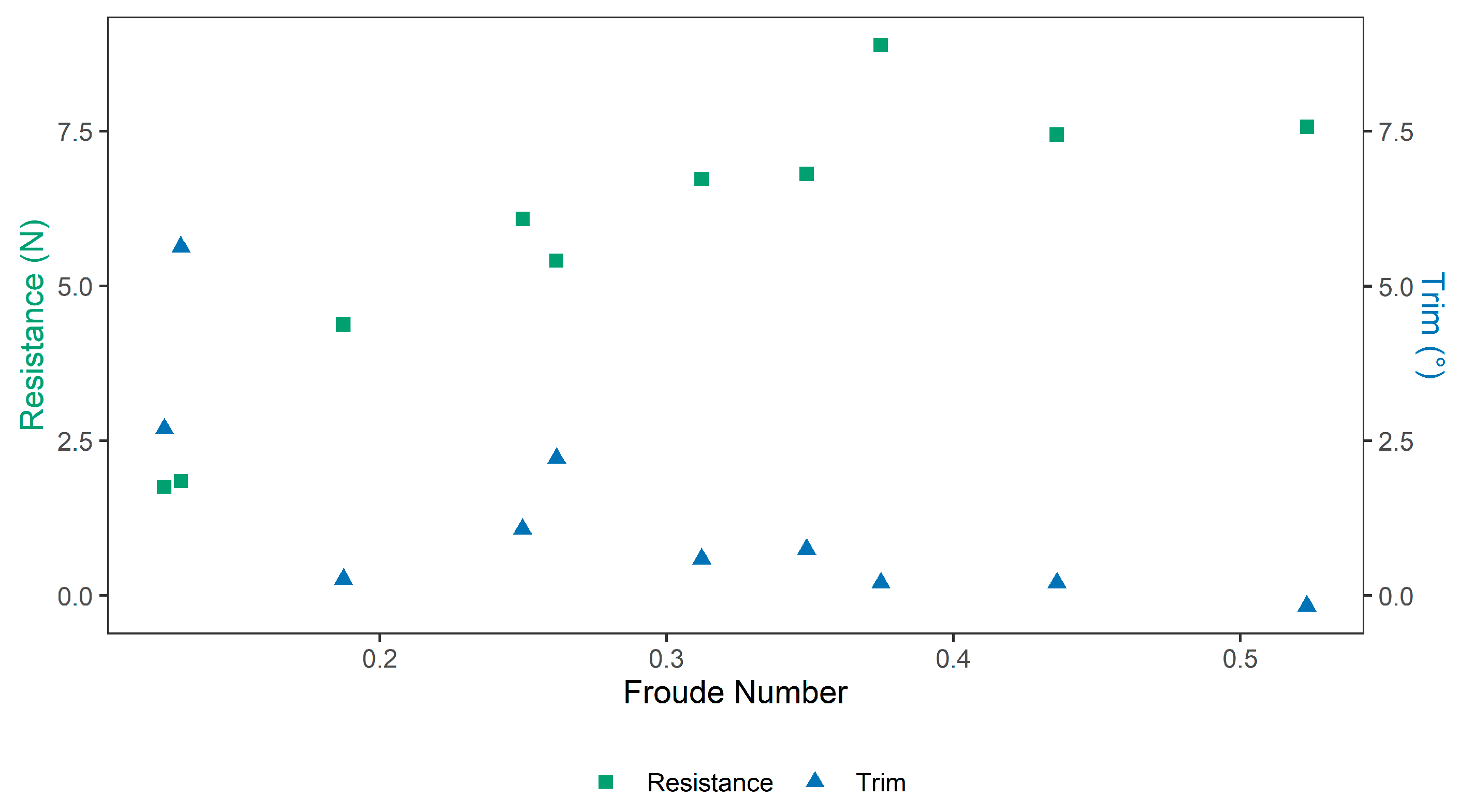
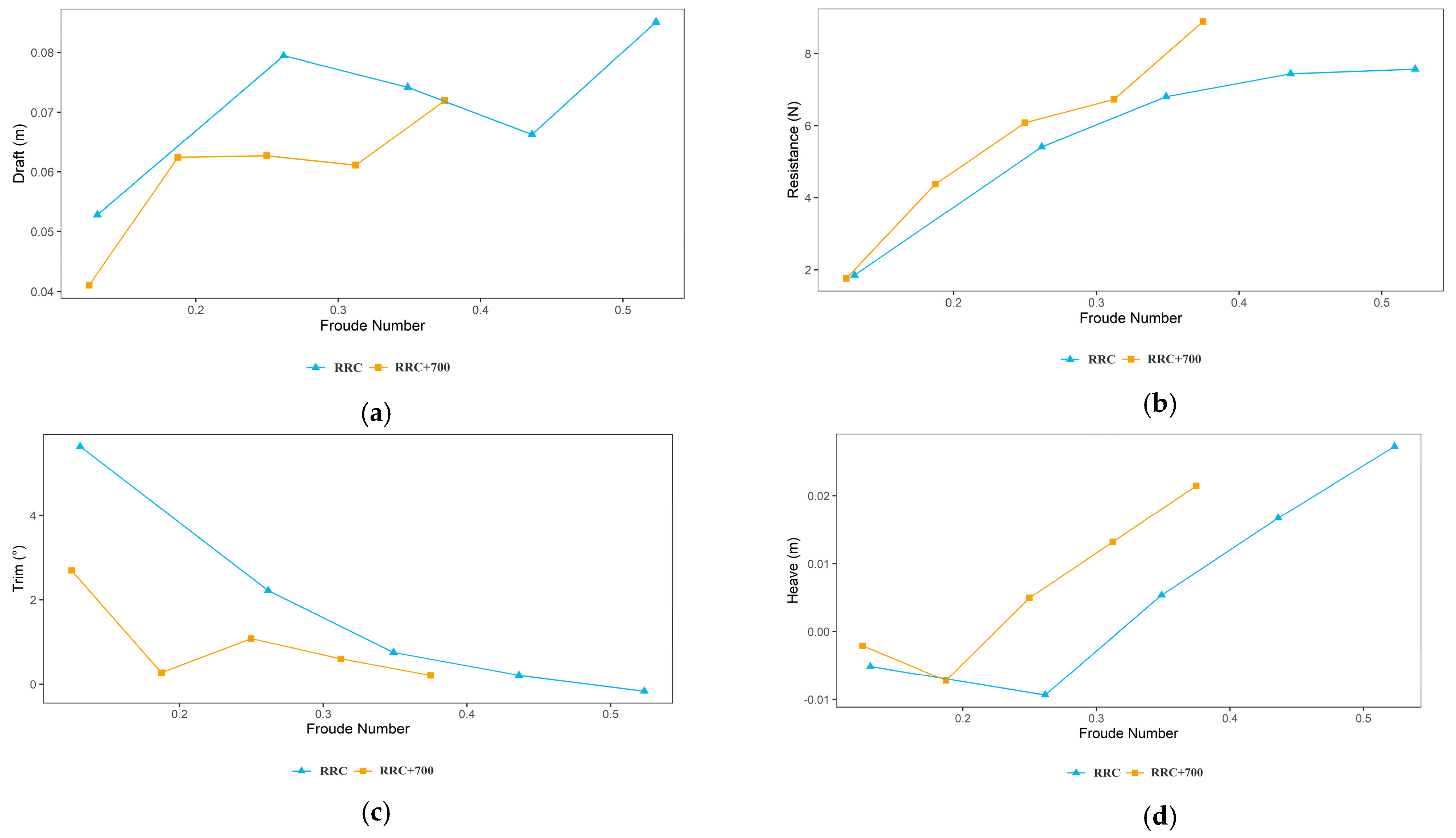
6.3. Results and Discussion

The following graphs are presented as part of the case study analysis to achieve the objective of the study. The results obtained from nine simulations at different Froude numbers were compared. The objective of this comparison was to determine the effects of speed and hull length on the draft, trim, resistance, and heave of the crafts.
Figure 9 shows the relationship between the resistance and trim obtained from the Froude number. Numerical predictions for the RRC and RRC+700 show an inverse relationship between the total resistance and trim at varied Froude numbers, where the trim values equate to higher resistance. This increase in resistance is due to the changes in the wetted area and pressure distribution of the craft at different Froude numbers. Figure 8 shows the wetted area distribution for the RRC at different speeds. At higher speeds, and hence higher Froude numbers, the RRC shows a reduction in the wetted area at the bow.
Other studies have evaluated the relationship between the trim and resistance, evaluating the effects of different trim angles for a given Froude number. Campbell et al. (2022) [10] studied the effects of different trim angles on resistance for a range of depth Froude numbers. They found that for a constant depth Froude number, higher trim values reduced the resistance of the craft, with a 10% increased resistance for a trim angle of −0.9° vs. 0.9°. These results agree with our observations of increased resistance for lower trim angles. On the other hand, Le et al. (2021) [33] found a nonlinear relationship between the trim and resistance, with resistance variations of around 2% for trim values between −0.054° to 0.054°. They predicted that the total resistance was approximately 2.6 times higher for Fr = 0.41 vs. Fr = 0.30. Similarly, observations from Campbell et al. (2022) indicated that the Froude number effect on resistance was higher than that of trim [10]. In the present study, individual effects of the Froude number and trim angle were not studied, as the craft was allowed to move freely under the conditions assumed. Based on the observations by Campbell et al. (2022) [10] and Le et al. (2021) [33], the higher resistance observed for lower trim values in the present study is potentially driven by the Froude number.
Figure 10a–d show the comparison of the RRC and RRC+700 models with Froude numbers for the draft, resistance, trim, and heave. This effect can be observed in the results presented by Suneela et al. (2021) [28], Campbell et al. (2022) [10], and Niazmand Bilandi et al. (2023) [27]. They compared experimental results with CFD predictions, demonstrating a clear trend in this relationship. However, Figure 10b reveals a difference in the total resistance between the RRC and RRC+700 hulls. The RRC+700 hull exhibited a higher resistance than the RRC hull. This result indicates that despite having lower dynamic trim values (Figure 10c) and higher heave values (Figure 10d), more power is required to move the watercraft.
This effect indicates that it is possible to reduce the draft of a semi-planing or planing watercraft by decreasing the trim and increasing the heave with an increase in length. However, this will be reflected in an increase in the total resistance of the watercraft. An interesting effect occurs in studies related to planing watercrafts and the inclusion of appendages, which substantially improves the dynamic trim of the watercraft. This can be seen in the work by Suneela et al. (2021) [28], where the inclusion of an interceptor decreased the trim and reduced the total resistance. This would improve the current condition of the RRC+700 hull. However, it is also important to note that such an appendix has a negative effect on resistance at low speeds and, therefore, low Froude numbers. As the RRC operates in a semi-planing range with Froude numbers below one, it may be less beneficial to add an appendix as it would negatively impact the resistance of the hull.
Sheingar et al. (2014) [34] also presented results from an analysis of V-shaped planing hulls, which achieve a reduction in resistance rate and heave through hydrofoil-type appendages. Experimental and numerical results from this study exhibited a similar behavior to that shown in Figure 10c regarding the decrease in the trim as the Froude number increases.

7. Conclusions

This paper studied the performance of a shallow-draft watercraft, comparing the effects on the trim, heave, and resistance, caused by the increase of 700 mm in the hull length of the RRC through CFD simulations at three navigation speeds. The results showed a reduction in the trim of the RRC+700 and an increase in the heave. An increase in resistance was also evident, affecting the power required to navigate and the energy consumption in the propulsion system.
The increase in heave was shown as part of the objective of the study because by increasing this parameter, the watercraft rose in position in the z-axis. This action produced a separation of the hull of the watercraft from the bottom of the river. Finally, this translated into a shallower draft for the watercraft. However, in the case of the RRC+700, the increase in heave was not considerable to reduce the hull wetted length, which could have caused an improvement in the decrease in hull resistance.
As part of the limitations, this work considered a low computation capacity to run all the simulations. Therefore, the simulations were performed considering a first-order temporal discretization, and the tests employed only a single speed to verify Hull No. 2743 with the experimental results. In addition, the lack of similar studies that compare the effect of hull length variation on the trim, heave, and resistance parameters limited the expansion of the discussion and enrichment of the study.
As part of future work, a new study should consider more than two hulls to study the effect of the change in length on the trim, heave, and resistance. Additionally, the analysis of the RRC and RRC+700 hulls should consider the inclusion of appendages that can improve the resistance performance of the RRC+700 hull at suitable operating speeds.

Author Contributions

Conceptualization, E.P.-S. and L.D.L.-R.; methodology, C.C.-F. and L.D.L.-R.; software, L.D.L.-R.; validation, L.D.L.-R.; formal analysis, L.D.L.-R.; investigation, C.P.C.-D., E.P.-S. and L.D.L.-R.; resources, C.C.-F.; data curation, L.D.L.-R. and C.C.-F.; writing—original draft preparation, L.D.L.-R.; writing—review and editing, C.P.C.-D., J.E.C.-B., C.C.-F. and L.D.L.-R.; visualization, L.D.L.-R. and J.E.C.-B.; supervision, C.C.-F., J.E.C.-B. and E.P.-S.; project administration, E.P.-S. and J.E.C.-B.; funding acquisition, E.P.-S. All authors have read and agreed to the published version of the manuscript.

Funding

This study and APC were funded with resources from the Fondo Nacional de Financiamiento para la Ciencia, la Tecnología y la Innovación Francisco José De Caldas provided by Ministerio de Ciencia, and Tecnología e Innovación through the call 914 of 2022.

Institutional Review Board Statement

Not applicable.

Informed Consent Statement

Not applicable.

Data Availability Statement

Data will be made available upon request.

Acknowledgments

The authors are grateful for the funding and support provided by Minciencias for developing the project ECOTEA—Development of an eco-friendly electric watercraft within the energy transition framework for inland waterway transportation of cargo and passengers on the ATR River—code 2243-914-91527.

Conflicts of Interest

The authors declare no conflict of interest.

Abbreviations

This manuscript uses the following abbreviations:
B/TBeam-to-draft ratio
CADComputer-aided design
CFDComputational fluid dynamics
ITTCInternational Towing Tank Conference
LCGLongitudinal center of gravity
RRCRiver reconnaissance craft
URANSUnsteady Reynolds-averaged Navier–Stokes

References

  1. Camargo-Díaz, C.P.; Paipa-Sanabria, E.; Zapata-Cortes, J.A.; Briceño-Chaves, A.M.; Serna-Castaño, C.F. Review of Financing Mechanisms to Promote Decarbonization Alternatives in Rail and Inland Waterway Transport. Sustain. Sci. Pract. Policy 2023, 15, 966. [Google Scholar] [CrossRef]
  2. Wiegmans, B.; Konings, R. Inland Waterway Transport: Challenges and Prospects; Routledge: London, UK, 2016; ISBN 978-1-31757-566-5. [Google Scholar]
  3. De Barros, B.R.C.; De Carvalho, E.B.; Brasil Junior, A.C.P. Inland Waterway Transport and the 2030 Agenda: Taxonomy of Sustainability Issues. Clean. Eng. Technol. 2022, 8, 100462. [Google Scholar] [CrossRef]
  4. Hernández, A.E.; Macías, H.A. Los Intereses Nacionales Marítimos y Fluviales En Colombia. In Identidad e Intereses Nacionales de Colombia; Pastrana Buelvas, E., Reith, S., Cabrera Ortiz, F., Eds.; Fundación Konrad Adenauer y Escuela Superior de Guerra: Buenos Aires, Argentina, 2020; pp. 403–434. [Google Scholar]
  5. Ministerio de Transporte. Plan Maestro Fluvial de Colombia 2015; Ministerio de Transporte: Bogotá, Colombia, 2015.
  6. Schweighofer, J. The Impact of Extreme Weather and Climate Change on Inland Waterway Transport. Nat. Hazards 2014, 72, 23–40. [Google Scholar] [CrossRef]
  7. Pedersen, P.T. Review and Application of Ship Collision and Grounding Analysis Procedures. Mar. Struct. 2010, 23, 241–262. [Google Scholar] [CrossRef]
  8. Prakash, M.N.S.; Chandra, B. Numerical Estimation of Shallow Water Resistance of a River-Sea Ship Using CFD. Int. J. Comput. Appl. 2013, 71, 33–40. [Google Scholar]
  9. Alvarado, D.; Flores, E.; Paipa, E. Design and Validation by the Finite Element Method of the Structural Arrangement of a Riverine Low Draft Combat Boat. Ship Sci. Technol. 2021, 15, 21–35. [Google Scholar] [CrossRef]
  10. Campbell, R.; Terziev, M.; Tezdogan, T.; Incecik, A. Computational Fluid Dynamics Predictions of Draught and Trim Variations on Ship Resistance in Confined Waters. Appl. Ocean Res. 2022, 126, 103301. [Google Scholar] [CrossRef]
  11. Du, P.; Ouahsine, A.; Sergent, P.; Hu, H. Resistance and Wave Characterizations of Inland Vessels in the Fully-Confined Waterway. Ocean Eng. 2020, 210, 107580. [Google Scholar] [CrossRef]
  12. Mucha, P.; El Moctar, O.; Dettmann, T.; Tenzer, M. An Experimental Study on the Effect of Confined Water on Resistance and Propulsion of an Inland Waterway Ship. Ocean Eng. 2018, 167, 11–22. [Google Scholar] [CrossRef]
  13. Gómez Franco, A.; Montes Galván, O. Cálculos de Estabilidad de una Embarcación Rápida a Grandes Velocidades; Universitat Politècnica de Catalunya, Facultat de Nàutica de Barcelona, Departament de Ciència i Enginyeria Nàutiques: Barcelona, Spain, 2011; Enginyeria Tècnica Naval, especialitat en Propulsió i Serveis del Vaixell. [Google Scholar]
  14. Faltinsen, O.M. Hydrodynamics of High-Speed Marine Vehicles; Cambridge University Press: Cambridge, MA, USA, 2006; ISBN 978-0-52184-568-7. [Google Scholar]
  15. Barrass, C.B. (Ed.) Chapter 17—Ship Squat in Open Water and in Confined Channels. In Ship Design and Performance for Masters and Mates; Butterworth-Heinemann: Oxford, UK, 2004; pp. 148–163. ISBN 978-0-75066-000-6. [Google Scholar]
  16. Eloot, K.; Verwilligen, J.; Vantorre, M. An Overview of Squat Measurements for Container Ships in Restricted Water. In Proceedings of the International Conference on Safety and Operations in Canals and Waterways SOCW, Glasgow, UK, 15–16 September 2008; pp. 15–16. [Google Scholar]
  17. Morabito, M.G. Re-Analysis of Series 50 Tests of V-Bottom Motor Boats. In Proceedings of the SNAME Maritime Convention, Bellevue, WA, USA, 13 November 2013. [Google Scholar]
  18. Drouet, A.; Sergent, P.; Causeur, D.; Corrignan, P. Trim Optimisation in Waves. In Proceedings of the VII International Conference on Computational Methods in Marine Engineering, Nantes, France, 15–17 May 2017. [Google Scholar]
  19. Tran, T.G.; Van Huynh, Q.; Kim, H.C. Optimization Strategy for Planing Hull Design. Int. J. Nav. Archit. Ocean Eng. 2022, 14, 100471. [Google Scholar] [CrossRef]
  20. Martić, I.; Degiuli, N.; Borčić, K.; Grlj, C.G. Numerical Assessment of the Resistance of a Solar Catamaran in Shallow Water. J. Mar. Sci. Eng. 2023, 11, 1706. [Google Scholar] [CrossRef]
  21. Samuel, S.; Mursid, O.; Yulianti, S.; Kiryanto, K.; Iqbal, M. Evaluation of Interceptor Design to Reduce Drag on Planing Hull. Brodogradnja 2022, 73, 93–110. [Google Scholar] [CrossRef]
  22. Suneela, J.; Sahoo, P. Numerical Investigation of Interceptor Effect on Sea Keeping Behaviour of Planing Hull Advancing in Regular Head Waves. Brodogradnja 2021, 72, 73–92. [Google Scholar] [CrossRef]
  23. Degiuli, N.; Farkas, A.; Martić, I.; Zeman, I.; Ruggiero, V.; Vasiljević, V. Vienna model basin LTD Numerical and Experimental Assessment of the Total Resistance of a Yacht. Brodogradnja 2021, 72, 61–80. [Google Scholar] [CrossRef]
  24. Shih, T.-H.; Liou, W.W.; Shabbir, A.; Yang, Z.; Zhu, J. A New K-Epsilon Eddy Viscosity Model for High Reynolds Number Turbulent Flows: Model Development and Validation. Comput. Fluids 1994, 24, 227–238. [Google Scholar] [CrossRef]
  25. ITTC. Quality Manual 7.5-03-01-01: CFD General—Uncertainty Analysis in CFD Verification and Validation Methodology and Procedures. In Proceedings of the International Towing Tank Conference (ITTC), Zürich, Switzerland, 4 October 2017. [Google Scholar]
  26. Savitsky, D. Hydrodynamic Design of Planing Hulls. Mar. Technol. SNAME News 1964, 1, 71–95. [Google Scholar] [CrossRef]
  27. Niazmand Bilandi, R.; Dashtimanesh, A.; Mancini, S.; Vitiello, L. Comparative Study of Experimental and CFD Results for Stepped Planing Hulls. Ocean Eng. 2023, 280, 114887. [Google Scholar] [CrossRef]
  28. Suneela, J.; Krishnankutty, P.; Subramanian, V.A. Hydrodynamic Performance of Planing Craft with Interceptor-Flap Hybrid Combination. J. Ocean Eng. Mar. Energy 2021, 7, 421–438. [Google Scholar] [CrossRef]
  29. ITTC. Recommended Procedures and Guidelines: Practical Guidelines for Ship CFD Applications. In Proceedings of the International Towing Tank Conference (ITTC), Rio de Janeiro, Brazil, 28 August–3 September 2011. [Google Scholar]
  30. Leal, L.; Flores, E.; Fuentes, D.; Verma, B. Hydrodynamic Study of the Influence of Bulbous Bow Design for an Offshore Patrol Vessel Using Computational Fluid Dynamics. Ship Sci. Technol. 2018, 11, 29. [Google Scholar] [CrossRef]
  31. García, M.; Leal, L.; Verma, B.; Ruiz, N. Numerical Study for the Estimation of the Hydrodynamic Coefficients of Current Drag in Port Assistance Maneuvers (Dock) for the Colombian Navy Frigates by Means of CFD. Xiandai Shipin Keji 2022, 16, 35–42. [Google Scholar]
  32. Nagai, T.; Yoshida, Y. Minimum Resistance Hull Form of Planing Craft With Controlled Trim Angle. In Proceedings of the Sixth International Offshore and Polar Engineering Conference, Los Angeles, CA, USA, 26–31 May 1996. [Google Scholar]
  33. Le, T.-H.; Vu, M.T.; Bich, V.N.; Phuong, N.K.; Ha, N.T.H.; Chuan, T.Q.; Tu, T.N. Numerical Investigation on the Effect of Trim on Ship Resistance by RANSE Method. Appl. Ocean Res. 2021, 111, 102642. [Google Scholar] [CrossRef]
  34. Sheingart, Z. Hydrodynamics of High Speed Planing Hulls with Partially Ventilated Bottom and Hydrofoils; Massachusetts Institute of Technology, Department of Mechanical Engineering: Cambridge, MA, USA, 2014. [Google Scholar]
Figure 1. CAD model for Hull 2743 from Series 50: (a) top view, (b) isometric view (c) profile view and (d) front view.
Jmse 11 02328 g001
Figure 2. Graphical scheme for defining draft/draughts in a craft: (a) hydrostatic hull draught, (b) hydrodynamic hull draught, and (c) navigational draught.
Jmse 11 02328 g002
Figure 3. Lines and forms of the RRC hull: (a) profile view, (b) buttock line view, and (c) waterplane view.
Jmse 11 02328 g003
Figure 4. Deadrise and flare angles for the RRC.
Jmse 11 02328 g004
Figure 5. Functional model of the River Reconnaissance Craft (RRC).
Jmse 11 02328 g005
Figure 6. Computational domain boundary conditions.
Jmse 11 02328 g006
Figure 7. Overset meshing in the domain.
Jmse 11 02328 g007
Figure 8. Profile view of wetted surface at different hull speeds for RRC: (a) 9 Knots, (b) 12 Knots, and (c) 15 Knots.
Jmse 11 02328 g008
Figure 9. Relationship between resistance and trim with Froude number.
Jmse 11 02328 g009
Figure 10. Comparison of the RRC and RRC+700 with Froude Numbers (Numerical-CFD Study): (a) draft, (b) resistance, (c) trim, and (d) heave.
Jmse 11 02328 g010
Table 1. Parameters of the RRC and Hull 2743 from Series 50.
ParameterSymbolRRCHull 2743
Speed V 3.76 kn2.87 kn
Maximum moulded breadth at design water line B W L 0.59 m0.31 m
Froude number based on breadth( C V )1.561.62
Breadth-to-Draft Ratio B / T 7.176.00
Table 2. Main particular of the Reference Validation Watercraft.
Main ParticularSymbolRRCRRC+700
Length overall L O A 7.60 m8.30 m
Length of waterline L W L 7.04 m8.00 m
Breadth B 2.46 m2.46 m
Water Depth h 5 m 5 m
Draft/Draught T 0.343 m0.330 m
Displacement m 4.095 t4.135 t
Design Speed V K 15 kn15 kn
Longitudinal center of gravity (LCG) L C G 3.18 m3.60 m
Vertical position of the center of gravity K G 0.72 m0.72 m
Table 3. Solver parameters.
ParameterDescription
Solver3D, unsteady, implicit
Turbulence model Standard   k ε
Multiphase modelVOF
Pressure-velocity couplingSIMPLE
Turbulence model discretizationSecond order
Temporal discretizationFirst order
Table 4. RRC systematic series results.
Speed
( V )
Froude Number Based on Breadth ( C V )Dynamic Trim Angle
( θ V )
Wetted Keel Length
( L K )
Static Trim
( t s )
[ k n ][ m / s ] [ ° ][ m ][ m ]
94.630.963.1010.079
126.171.285.966.6512
157.721.595.606.2815
189.261.916.284.9518
2110.802.236.224.1021
2412.352.555.274.0624
2713.892.875.213.2327
3015.433.195.352.3230
3216.463.405.451.8432
Table 5. Results of systematic series for the configuration of initial conditions of the RRC+700 hull.
HULL–RRC+700 mm4.14 t—LCG (3.18 mm)
Speed
( V )
Froude Number Based on Breadth ( C V )Resistance
( R )
Effective Power ( P E )Brake Power
( P B )
Dynamic Trim Angle ( θ V )Static Trim
( t s )
[ k n ][ m / s ] [ k N ][ h p ][ H p ][ ° ][ m ]
94.630.964.0124.9245.312.450.49
126.171.285.3644.3980.714.770.64
157.721.605.8660.67110.314.680.59
189.261.925.8572.59131.985.290.54
2110.802.245.7282.9150.735.340.46
2412.352.565.794.32171.494.610.39
2713.892.885.82108.38197.054.410.30
3015.433.206.08125.79228.714.330.25
3216.463.416.32139.57253.714.280.19
Table 6. Parameters to initialize the simulation of the hulls.
Initial Trim−3° at 9 Knots in the Center of Coordinates for a Rigid Body
Initial Trim−6° at 12 knots and 15 knots in the center of coordinates for a rigid body
Release Time11 s
Ramp Time22 s
Table 7. Resistance results for hull No. 2743.
RT Tests [N]4.4720
RT model CFD [N]4.33
% Difference−3.175%
Table 8. Convergence condition.
ConditionType ConvergenceRange of Convergence
iMonotonic 0 < R i < 1
iiOscillatory R i < 0
iiiDivergence R i > 1
Table 9. Dimensions of the virtual towing tank.
RRC Simulation Mesh Verification Results
MeshNo. of Cells [u]Resistance [N]Total Resistance Coefficient Heave [m]Trim [°]Base Size [m]Remarks
Fine1,829,4068.4990.001599940.02216−1.34000.450Total stabilization
Medium1,475,1458.4740.001595240.01630−1.40000.500Total stabilization
Coarse1,187,2058.4110.001583510.01805−1.41550.550Total stabilization
Table 10. Error calculated using generalized Richardson extrapolation.
ParametersResult
x 3 0.550
x 2 0.500
x 1 0.450
r i 1.100
ε 21 −0.025
ε 32 −0.062
R i 0.401
p i 9.590
δ R E −1.67%
Disclaimer/Publisher’s Note: The statements, opinions and data contained in all publications are solely those of the individual author(s) and contributor(s) and not of MDPI and/or the editor(s). MDPI and/or the editor(s) disclaim responsibility for any injury to people or property resulting from any ideas, methods, instructions or products referred to in the content.

