
Vertical Monotonic and Cyclic Responses of a Bucket in Over-Consolidated Clay


Abstract
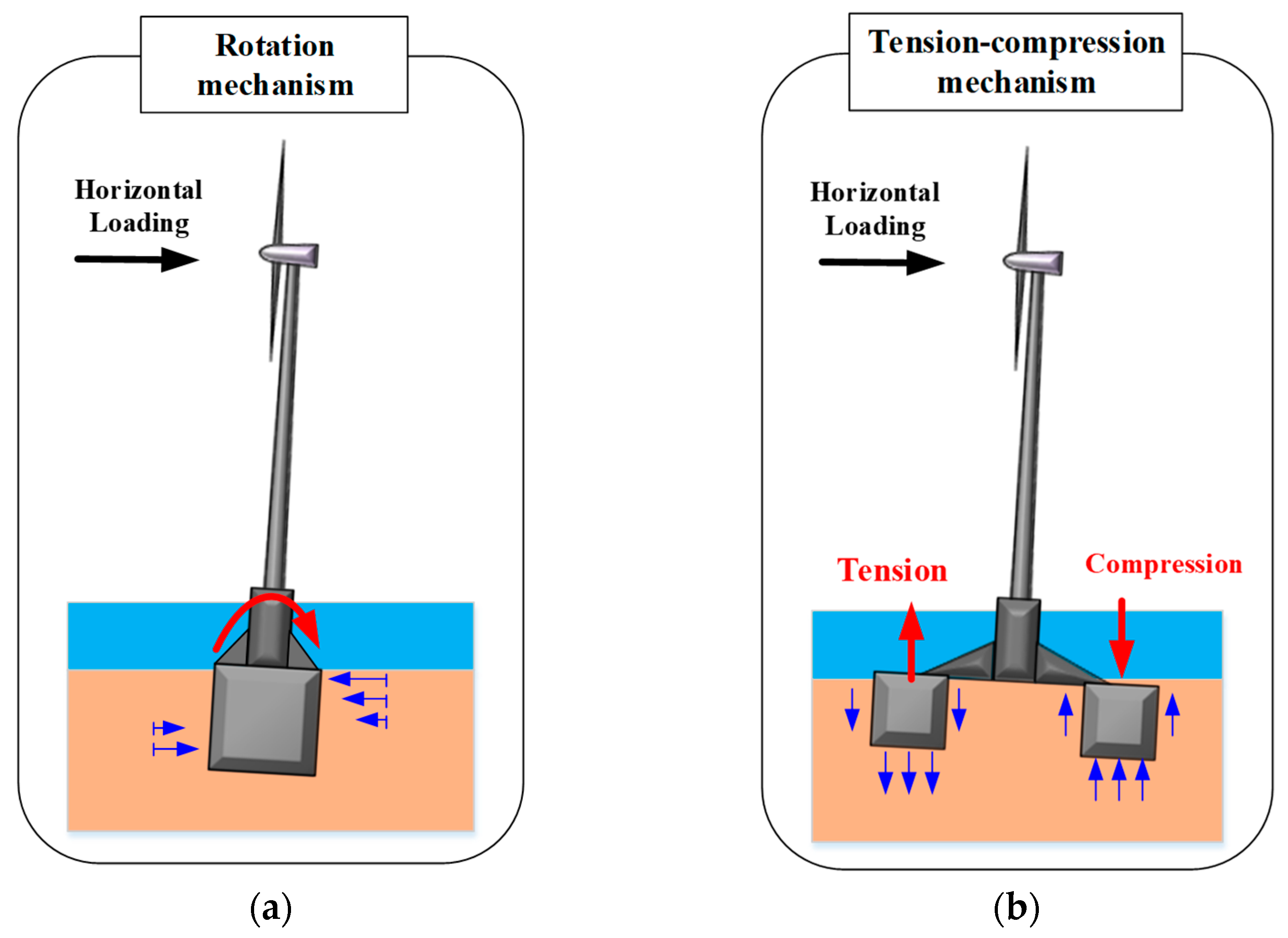
:1. Introduction
2. Experimental Equipment and Soil Preparation
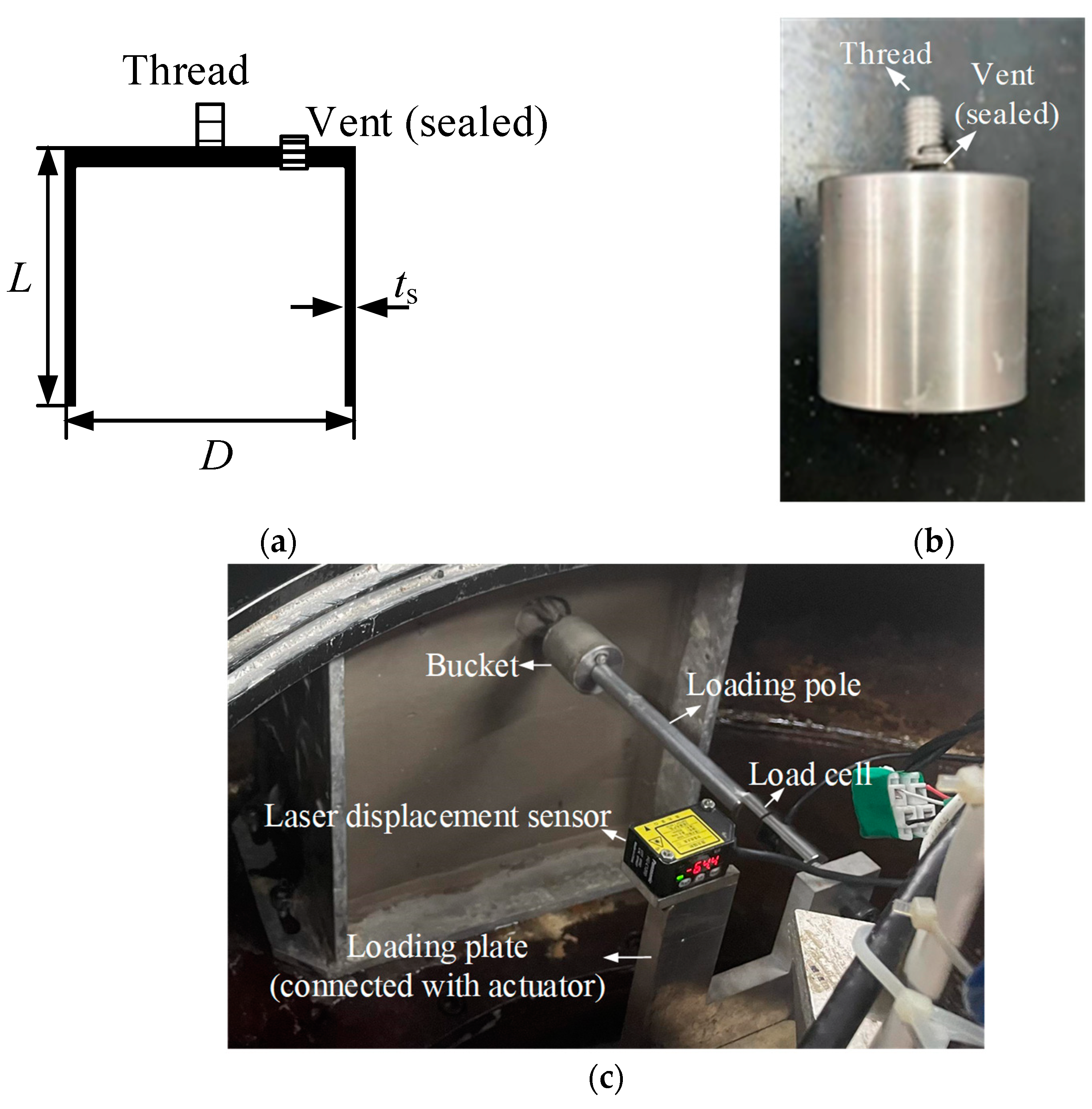
2.1. Experimental Equipment and Model Bucket
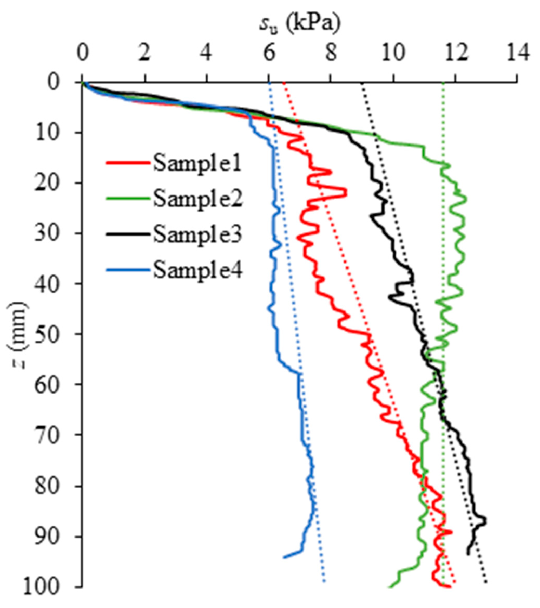
2.2. Sample Preparation and Strength Profile
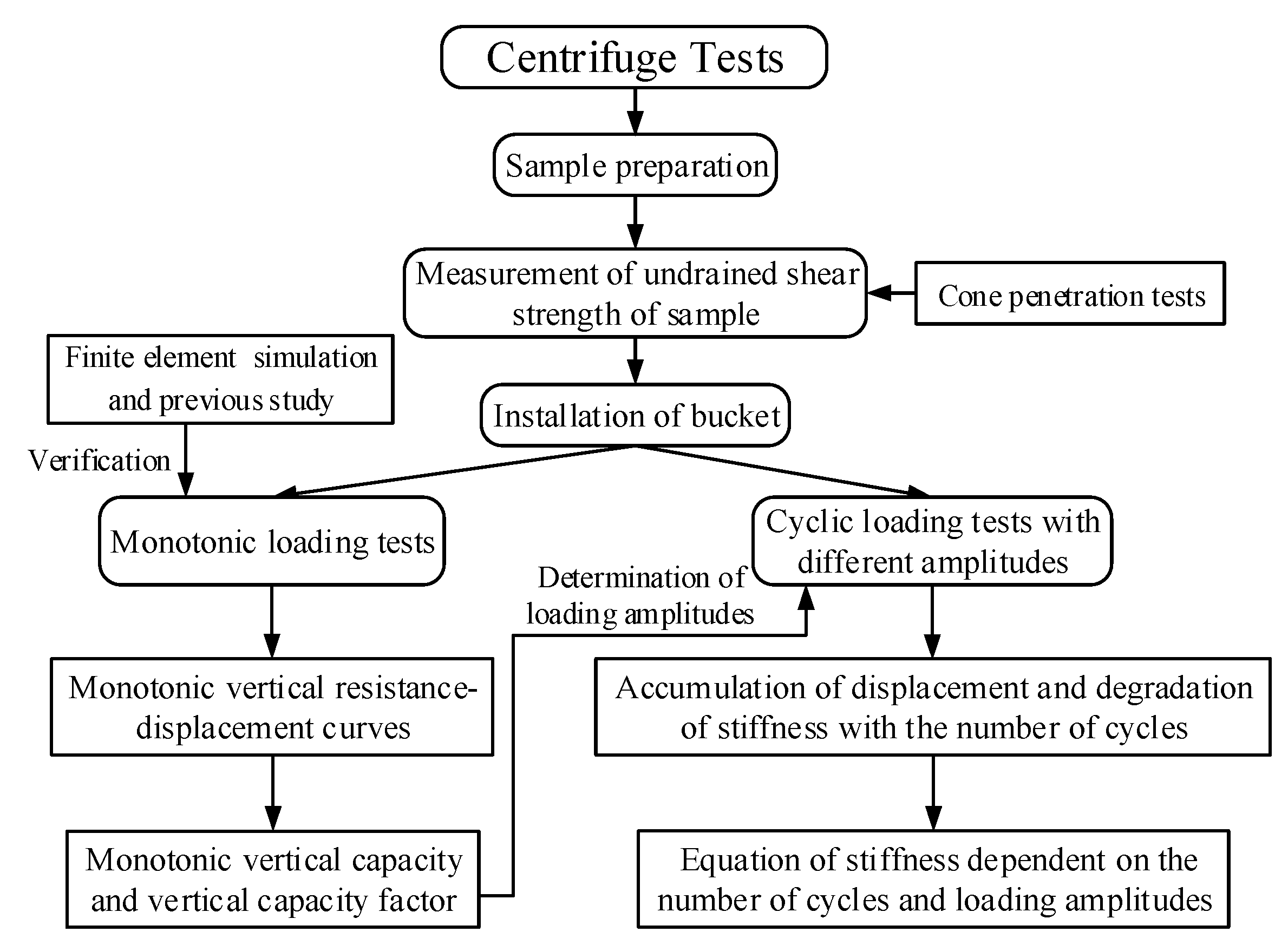
3. Experimental Arrangements
4. Installation
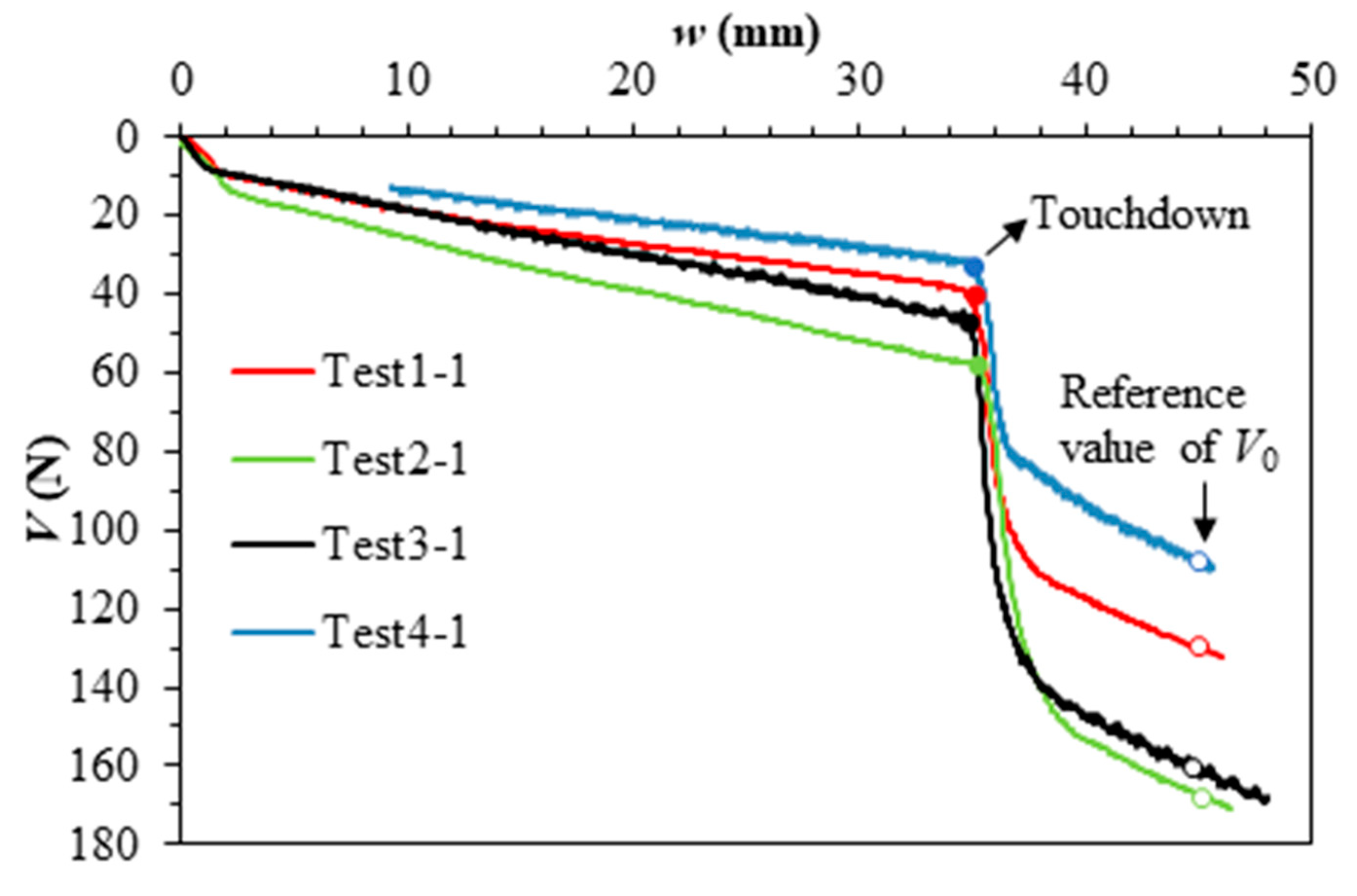
5. Monotonic Loading
6. Cyclic Loading
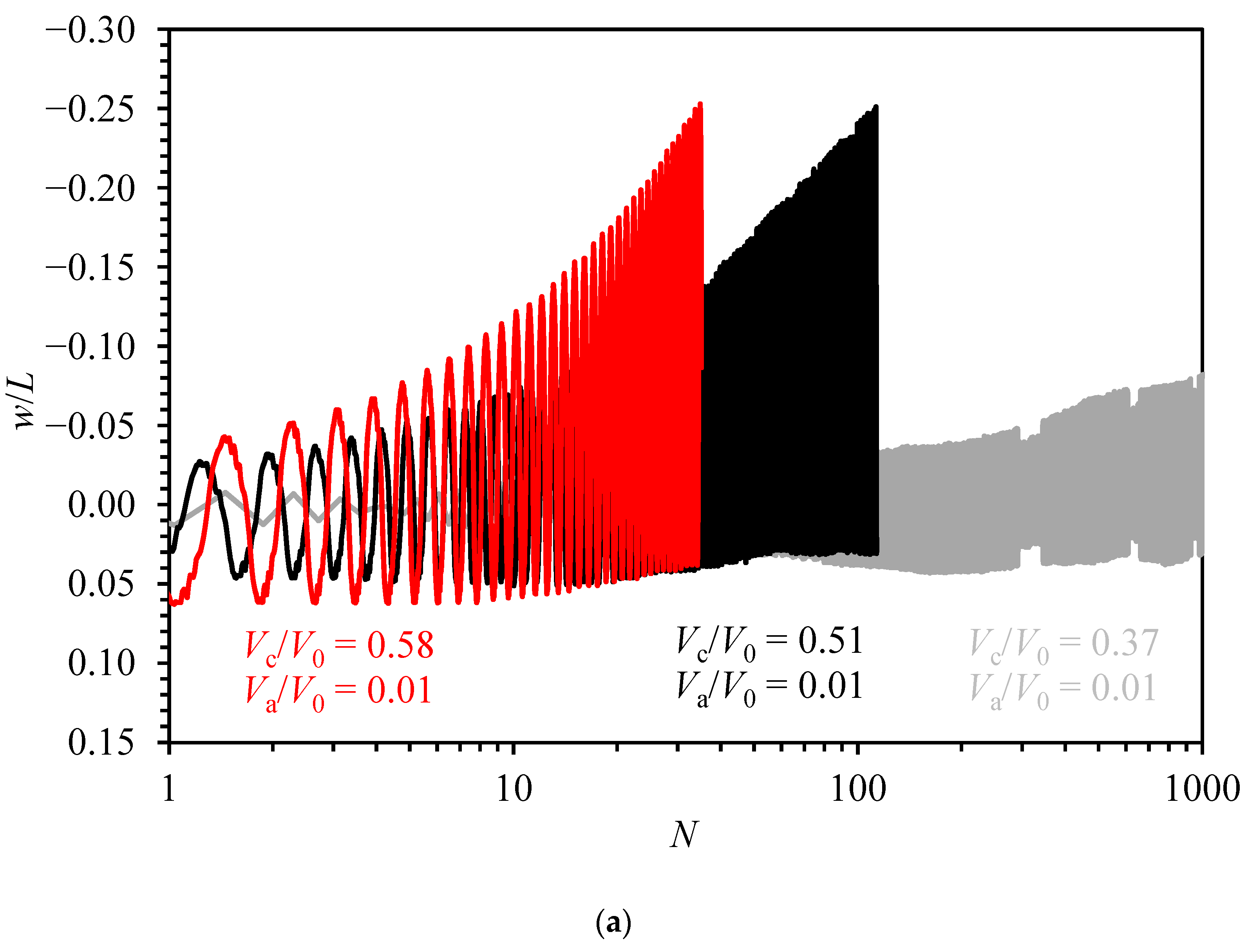
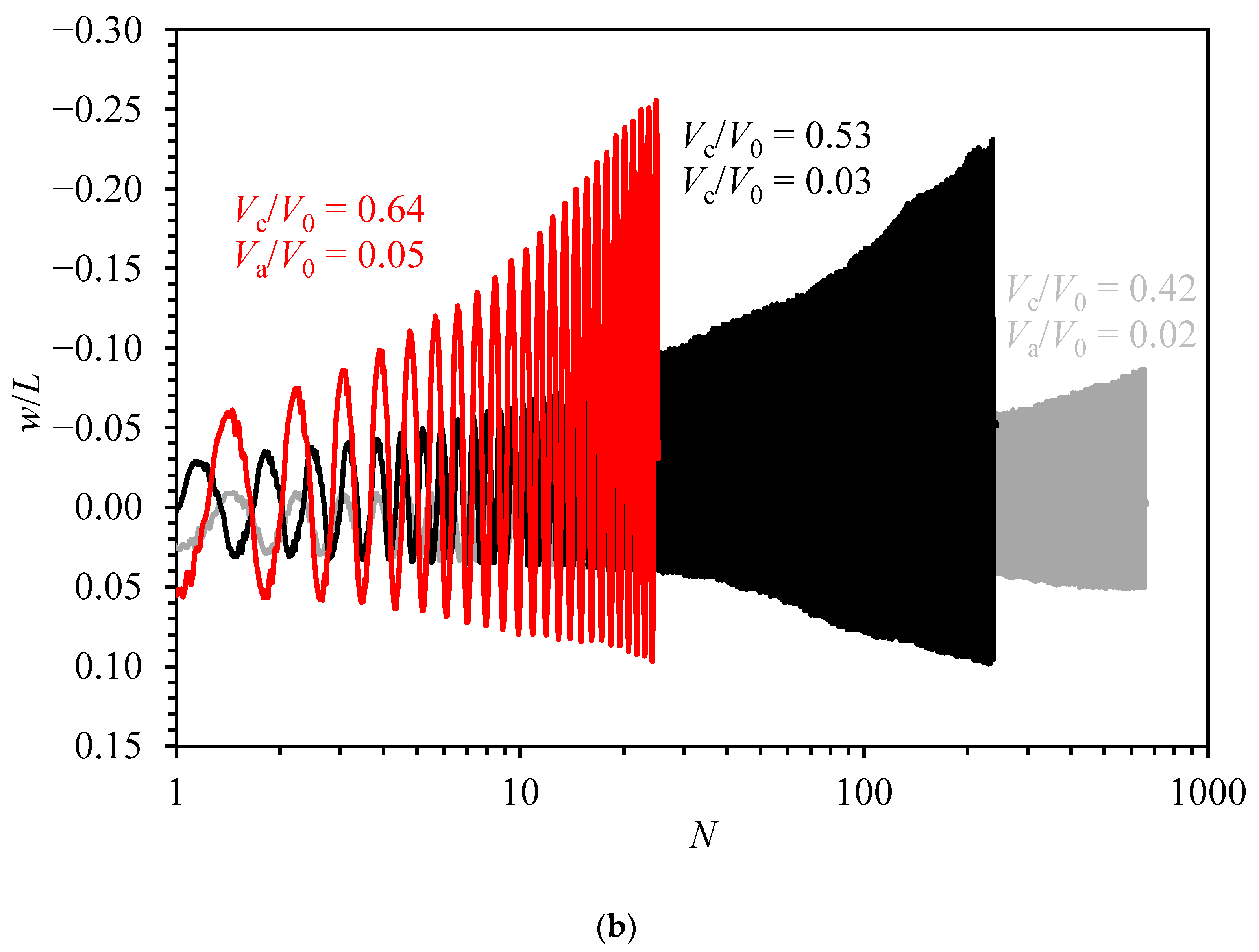
6.1. Evolution of Vertical Displacement
6.2. Evolution of Secant Stiffness
7. Conclusions
- (1)
- The vertical capacities by centrifuge tests and numerical simulations are with errors less than 6%. The vertical capacity factors are in the range of 9.5–10.9.
- (2)
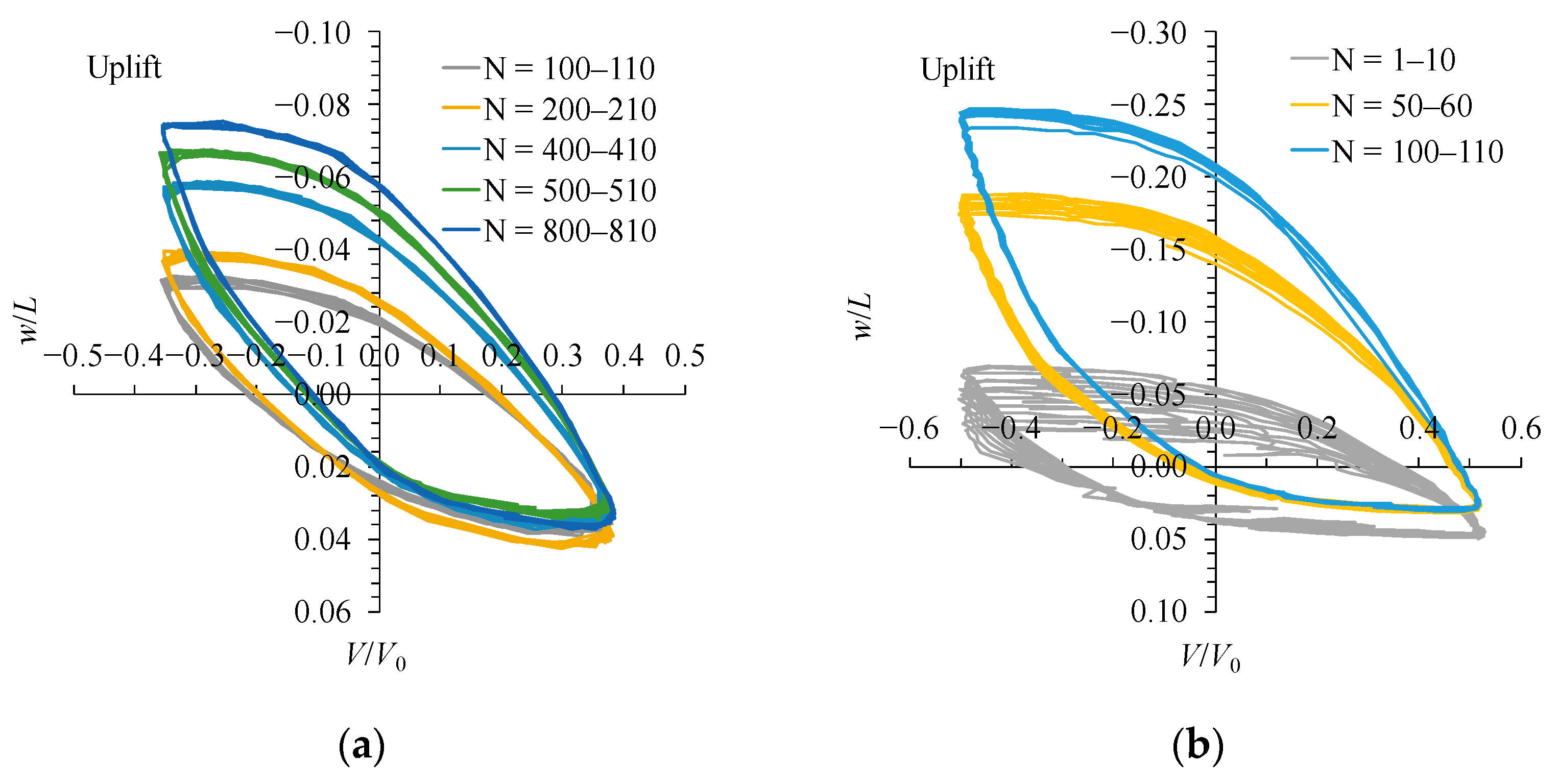
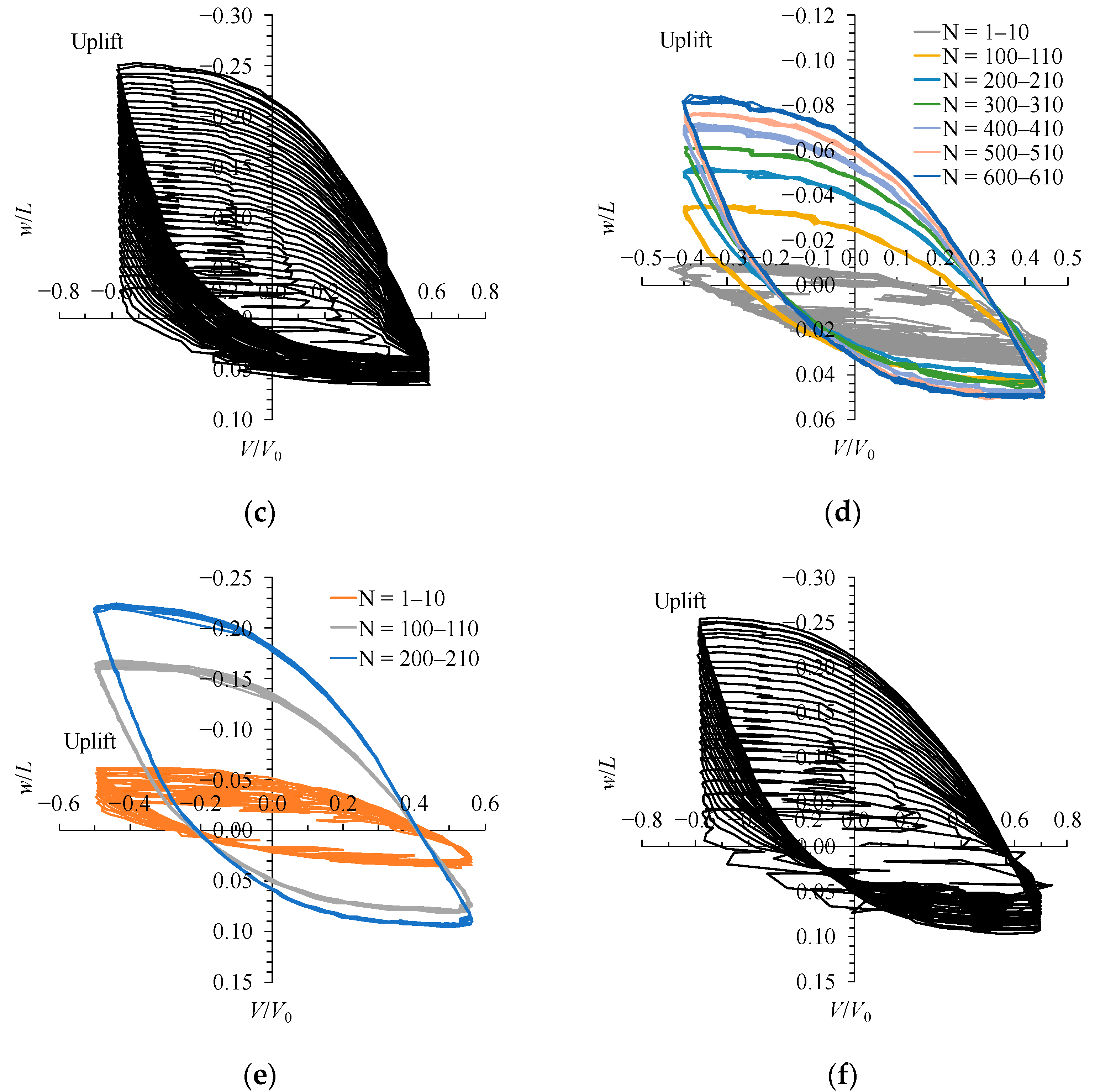
- Under symmetric vertical loading, the normalized average displacements of the bucket, varied between −0.024 and −0.109 in six tests, are on the tensile side due to the tensile capacity being lower than the compressive. The accumulation rates of average displacement and displacement amplitude of the bucket are larger under higher Vc/V0 due to the lower effective stress.
- (3)
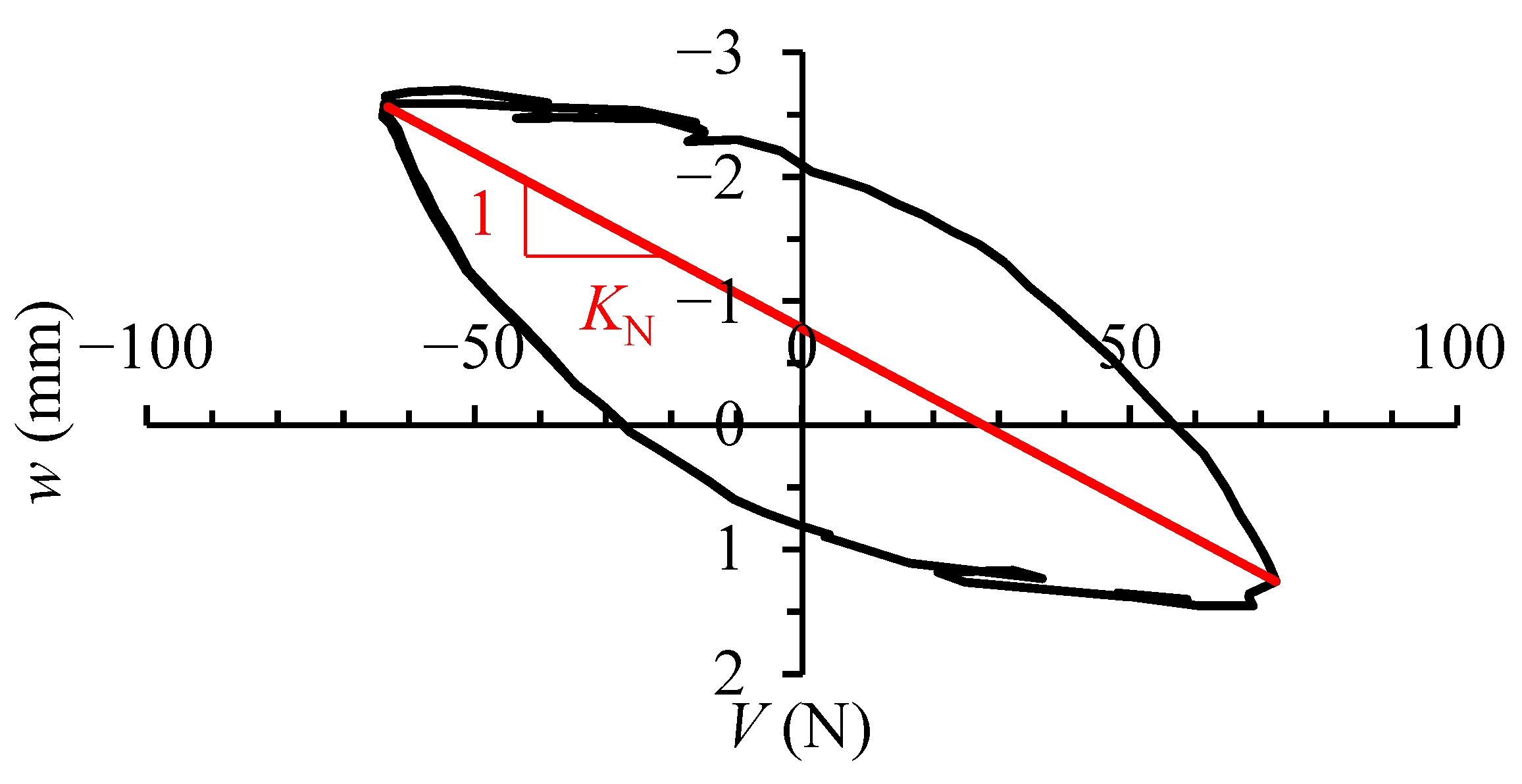
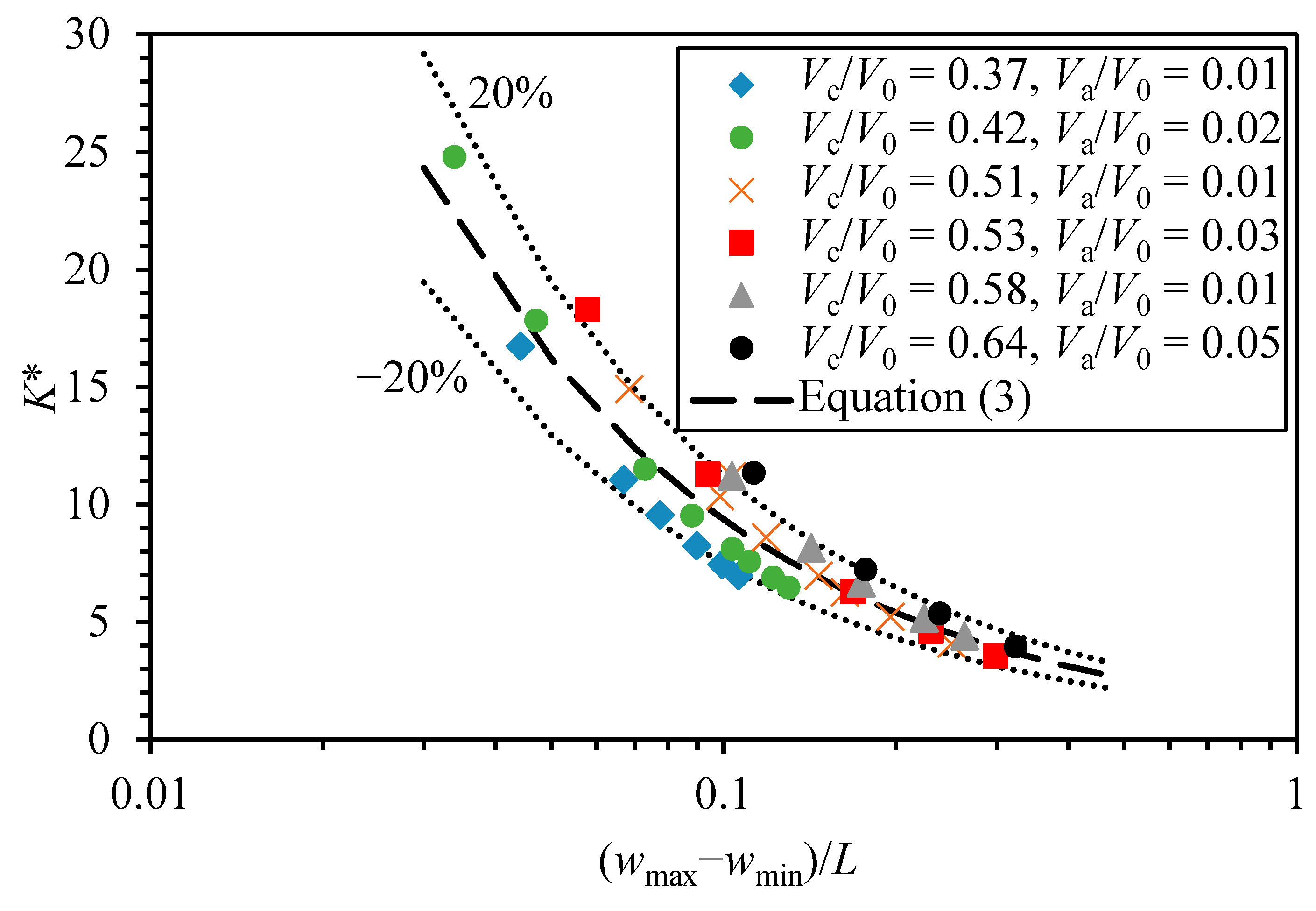
- The secant stiffness of the bucket is decreased with Vc/V0 and N. Partial drainage may occur over 996 cycles with Vc/V0 = 0.37, due to the loading time in the prototype of 137 d and the dimensionless time factor T > 0.18. Based on the experimental results, two simplified equations are proposed to describe the evolution of the secant stiffness of the bucket.
Author Contributions
Funding
Institutional Review Board Statement
Informed Consent Statement
Data Availability Statement
Conflicts of Interest
References
- Houlsby, G.; Byrne, B. Suction Caisson Foundations for Offshore Wind Turbines and Anemometer Masts. Wind Eng. 2000, 24, 249–255. [Google Scholar] [CrossRef]
- Faizi, K.; Faramarzi, A.; Dirar, S.; Chapman, D. Investigating the Monotonic Behaviour of Hybrid Tripod Suction Bucket Foundations for Offshore Wind Towers in Sand. Appl. Ocean Res. 2019, 89, 176–187. [Google Scholar] [CrossRef]
- Randolph, M.; Gourvenec, S. Offshore Geotechnical Engineering, 1st ed.; CRC Press: London, UK, 2011; ISBN 978-1-315-27247-4. [Google Scholar]
- Vulpe, C. Design Method for the Undrained Capacity of Skirted Circular Foundations under Combined Loading: Effect of Deformable Soil Plug. Géotechnique 2015, 65, 669–683. [Google Scholar] [CrossRef]
- Achmus, M.; Kuo, Y.S.; Abdel-Rahman, K. Behavior of Monopile Foundations under Cyclic Lateral Load. Comput. Geotech. 2009, 36, 725–735. [Google Scholar] [CrossRef]
- Jeong, Y.; Kim, J.H.; Park, H.J.; Kim, D. Cyclic Behavior of Unit Bucket for Tripod Foundation System Supporting Offshore Wind Turbine via Model Tests. Wind Energy 2018, 22, 257–268. [Google Scholar] [CrossRef]
- Houlsby, G.T.; Kelly, R.B.; Huxtable, J.; Byrne, B.W. Field Trials of Suction Caissons in Clay for Offshore Wind Turbine Foundations. Géotechnique 2005, 55, 287–296. [Google Scholar] [CrossRef]
- He, B.; Jiang, J.; Cheng, J.; Zheng, J.; Wang, D. The Capacities of Tripod Bucket Foundation under Uniaxial and Combined Loading. Ocean Eng. 2021, 220, 108400. [Google Scholar] [CrossRef]
- Kim, D.J.; Choo, Y.W.; Kim, J.H.; Kim, S.; Kim, D.S. Investigation of Monotonic and Cyclic Behavior of Tripod Suction Bucket Foundations for Offshore Wind Towers Using Centrifuge Modeling. J. Geotech. Geoenvironmental Eng. 2014, 140, 04014008. [Google Scholar] [CrossRef]
- Carbon Trust. Suction Installed Caisson Foundations for Offshore Wind: Design Guidelines, 1st ed.; Carbon Trust: London, UK, 2019; pp. 1–92. [Google Scholar]
- Villalobos, F.A.; Byrne, B.W.; Houlsby, G.T. Model Testing of Suction Caissons in Clay Subjected to Vertical Loading. Appl. Ocean Res. 2010, 32, 414–424. [Google Scholar] [CrossRef]
- Jeong, Y.; Ko, K.W.; Kim, D.S.; Kim, J.H. Studies on Cyclic Behavior of Tripod Suction Bucket Foundation System Supporting Offshore Wind Turbine Using Centrifuge Model Test. Wind Energy 2020, 24, 515–529. [Google Scholar] [CrossRef]
- Wang, Y.; Zhang, S.; Xu, H.; Zhang, Y.; Gaunt, P.; Ren, B.; Zhang, Y.; Yubin, R. Site Investigation and Soil Parameters for Offshore Suction Bucket Design: A Case Study of Houhu Wind Turbine. Ocean Eng. 2022, 255, 111458. [Google Scholar] [CrossRef]
- Lau, B.H. Cyclic Behaviour of Monopile Foundations for Offshore Wind Turbines in Clay. Ph.D. Thesis, University of Cambridge, Cambridge, UK, 2015. [Google Scholar]
- Bransby, M.F.; Yun, G.J. The Undrained Capacity of Skirted Strip Foundations under Combined Loading. Géotechnique 2009, 59, 115–125. [Google Scholar] [CrossRef]
- Hung, L.C.; Kim, S.R. Evaluation of Vertical and Horizontal Bearing Capacities of Bucket Foundations in Clay. Ocean Eng. 2012, 52, 75–82. [Google Scholar] [CrossRef]
- Cassidy, M.J.; Byrne, B.W.; Randolph, M.F. A Comparison of the Combined Load Behaviour of Spudcan and Caisson Foundations on Soft Normally Consolidated Clay. Géotechnique 2004, 54, 91–106. [Google Scholar] [CrossRef]
- Gourvenec, S.; Acosta-Martinez, H.E.; Randolph, M.F. Experimental Study of Uplift Resistance of Shallow Skirted Foundations in Clay under Transient and Sustained Concentric Loading. Géotechnique 2009, 59, 525–537. [Google Scholar] [CrossRef]
- Supachawarote, C. Inclined Load Capacity of Suction Caisson in Clay. Ph.D. Thesis, University of Western Australia, Perth, Australia, 2006. [Google Scholar]
- Leblanc, C.; Houlsby, G.T.; Byrne, B.W. Response of Stiff Piles in Sand to Long-Term Cyclic Lateral Loading. Géotechnique 2010, 60, 79–90. [Google Scholar] [CrossRef]
- Byrne, B.; Houlsby, G. Experimental Investigations of Response of Suction Caissons to Transient Vertical Loading. J. Geotech. Geoenvironmental Eng. 2002, 128, 926–939. [Google Scholar] [CrossRef]
- Byrne, B.; Houlsby, G. Experimental Investigations of the Response of Suction Caissons to Transient Combined Loading. J. Geotech. Geoenvironmental Eng. 2004, 130, 240–253. [Google Scholar] [CrossRef]
- Senders, M. Suction Caissons in Sand as Tripod Foundations for Offshore Wind Turbines. Ph.D. Thesis, University of Western Australia, Perth, Australia, 2009. [Google Scholar]
- Bienen, B.; Klinkvort, R.T.; O’Loughlin, C.D.; Zhu, F.; Byrne, B.W. Suction Caissons in Dense Sand, Part II: Vertical Cyclic Loading into Tension. Géotechnique 2018, 68, 953–967. [Google Scholar] [CrossRef]
- Stapelfeldt, M.; Bienen, B.; Grabe, J. Influence of Low-Permeability Layers on the Installation and the Response to Vertical Cyclic Loading of Suction Caissons. J. Geotech. Geoenvironmental Eng. 2021, 147, 04021076. [Google Scholar] [CrossRef]
- Kelly, R.; Houlsby, G.; Byrne, B. A Comparison of Field and Laboratory Tests of Caisson Foundations in Sand and Clay. Géotechnique 2006, 56, 617–626. [Google Scholar] [CrossRef]
- Zhang, Y.; Sudhakaran, K.; Askarinejad, A. Centrifuge Modelling of Suction Caissons Subjected to Cyclic Loading in Tension. In Proceedings of the 4th European Conference on Physical Modelling in Geotechnics, Lulea, Sweden, 15 March 2020. [Google Scholar]
- Gütz, P.; Achmus, M. Suction Bucket Foundations under Cyclic Tensile Loading–Physical and Numerical Modeling. Geotech. Test. J. 2021, 44, 20200056. [Google Scholar] [CrossRef]
- Kou, H.; Fang, W.; Zhou, N.; Huang, J.; Zhang, X. Dynamic Response of Single-Bucket Foundation in Clay under Vertical Variable Amplitude Cyclic Loadings. Ocean Eng. 2023, 273, 113973. [Google Scholar] [CrossRef]
- Chen, W.; Randolph, M. Uplift Capacity of Suction Caissons under Sustained and Cyclic Loading in Soft Clay. J. Geotech. Geoenvironmental Eng. 2007, 133, 1352–1363. [Google Scholar] [CrossRef]
- Zografou, D.; Gourvenec, S.; O’Loughlin, C. Vertical Cyclic Loading Response of Shallow Skirted Foundation in Soft Normally Consolidated Clay. Can. Geotech. J. 2018, 56, 473–483. [Google Scholar] [CrossRef]
- Iskander, M.; El-Gharbawy, S.; Olson, R. Performance of Suction Caissons in Sand and Clay. Can. Geotech. J. 2002, 39, 576–584. [Google Scholar] [CrossRef]
- Al-Janabi, H.; Aubeny, C. Experimental and Numerical Investigation of the Performance of Piles and Suction Caissons Subjected to Inclined Cyclic Loading in Cohesive Soils. J. Geotech. Geoenvironmental Eng. 2022, 148, 04022036. [Google Scholar] [CrossRef]
- Wang, T.; Yu, S.; Liu, W.; Bao, X.; Liu, J. Cyclic Bearing Mechanism of Suction Caissons Supporting Offshore Wind Turbines in Clay. China Ocean Eng. 2021, 35, 135–144. [Google Scholar] [CrossRef]
- Zhou, N.; Kou, H.; Chen, Q. Horizontal Cyclic Response of Bucket Caisson for Offshore Wind Turbines in Over-Consolidated Clay. Appl. Ocean Res. 2021, 118, 102973. [Google Scholar] [CrossRef]
- Zhao, X.L.; Wang, X.; Ding, P.C.; Sui, S.H.; Deng, W.N. Development and Influence of Pore Pressure around a Bucket Foundation in Silty Soil. J. Mar. Sci. Eng. 2022, 10, 2020. [Google Scholar] [CrossRef]
- Zhu, W.; Dai, G.; Wang, B.; Gong, W.; Sun, J.; Hu, H. Study on cyclic characteristics and equivalent cyclic creep model of the soft clay at the bottom of suction caisson foundation. ROCK SOIL Mech. 2022, 43, 466–478. [Google Scholar] [CrossRef]
- Vicent, S.; Kim, S.R.; Van Tung, D.; Bong, T. Effect of Loading Rate on the Pullout Capacity of Offshore Bucket Foundations in Sand. Ocean Eng. 2020, 210, 107427. [Google Scholar] [CrossRef]
- Chung, S.F.; Randolph, M.F.; Schneider, J.A. Effect of Penetration Rate on Penetrometer Resistance in Clay. J. Geotech. Geoenvironmental Eng. 2006, 132, 1188–1196. [Google Scholar] [CrossRef]
- Lehane, B.M.; O’loughlin, C.D.; Gaudin, C.; Randolph, M.F. Rate Effects on Penetrometer Resistance in Kaolin. Géotechnique 2009, 59, 41–52. [Google Scholar] [CrossRef]
- Zhang, W.; Liu, K.; Wang, D.; Zheng, J. Coefficient of Consolidation Measured by Cone Penetration Tests in Overconsolidated Cohesive Soils. Ocean Eng. 2023, 276, 114301. [Google Scholar] [CrossRef]
- Lunne, T.; Robertson, P.; Powell, J. Cone Penetration Testing in Geotechnical Practice. Soil Mech. Found. Eng. 1997, 46, 237. [Google Scholar] [CrossRef]
- Low, H.E.; Lunne, T.; Andersen, K.H.; Sjursen, M.A.; Li, X.; Randolph, M.F. Estimation of Intact and Remoulded Undrained Shear Strengths from Penetration Tests in Soft Clays. Géotechnique 2010, 60, 843–859. [Google Scholar] [CrossRef]
- Liu, B.; Zhang, Y.; Ma, Z.; Andersen, K.; Jostad, H.; Liu, D.; Pei, A. Design Considerations of Suction Caisson Foundations for Offshore Wind Turbines in Southern China. Appl. Ocean Res. 2020, 104, 102358. [Google Scholar] [CrossRef]
- Dong, Y.K.; Wang, D.; Randolph, M. Investigation of Impact Forces on Pipeline by Submarine Landslide with Material Point Method. Ocean Eng. 2017, 146, 21–28. [Google Scholar] [CrossRef]
- Sun, Q.L.; Wang, Q.; Shi, F.Y.; Alves, T.; Gao, S.; Xie, X.N.; Wu, S.G.; Li, J.B. Runup of Landslide-generated Tsunamis Controlled by Paleogeography and Sea-level Change. Commun. Earth Environ. 2022, 3, 244. [Google Scholar] [CrossRef]
- Randolph, M.F. Offshore Design Approaches and Model Tests for Sub-Failure Cyclic Loading of Foundations. In Mechanical Behaviour of Soils under Environmentally Induced Cyclic Loads; Di Prisco, C., Wood, D.M., Eds.; CISM Courses and Lectures; Springer: Vienna, Austria, 2012; pp. 441–480. ISBN 978-3-7091-1068-3. [Google Scholar]
- Zhu, F.Y.; O’Loughlin, C.D.; Bienen, B.; Cassidy, M.J.; Morgan, N. The Response of Suction Caissons to Long-Term Lateral Cyclic Loading in Single-Layer and Layered Seabeds. Géotechnique 2018, 68, 729–741. [Google Scholar] [CrossRef]
- Gourvenec, S.; Randolph, M. Consolidation beneath Circular Skirted Foundations. Int. J. Geomech. 2010, 10, 22–29. [Google Scholar] [CrossRef]
- Feng, X.; Gourvenec, S. Consolidated Undrained Load-Carrying Capacity of Subsea Mudmats under Combined Loading in Six Degrees of Freedom. Géotechnique 2015, 65, 563–575. [Google Scholar] [CrossRef]
- DNV-RP-E303 Geotechnical Design and Installation of Suction Anchors in Clay. Available online: https://www.dnv.com/Default (accessed on 22 October 2023).
- Manuals-PLAXIS-GeoStudio|PLAXIS Wiki-GeoStudio|PLAXIS-Bentley Communities. Available online: https://communities.bentley.com/products/geotech-analysis/w/wiki/46137/manuals---plaxis (accessed on 25 September 2023).
- Kanmin, S.; Jiang, J.; Wang, D.; Zheng, J. Capacities of Tripod Bucket Foundation under Uniaxial and Combined Loading Considering Adhesion Factor. Mar. Georesources Geotechnol. 2021, 40, 1520–1528. [Google Scholar] [CrossRef]
- Hung, L.C.; Lee, S.H.; Vicent, S.; Kim, S.R. An Experimental Investigation of the Cyclic Response of Bucket Foundations in Soft Clay under One-Way Cyclic Horizontal Loads. Appl. Ocean Res. 2018, 71, 59–68. [Google Scholar] [CrossRef]


| Parameters | Values |
|---|---|
| Specific gravity, Gs | 2.70 |
| Effective unit weight, γ′ (kN/m3) | 6.97 |
| Liquid limit (%) | 42.8 |
| Plastic limit (%) | 20.8 |
| Sensitivity, St | 2.1 |
| Vertical coefficient of consolidation, cv (mm2/s) (σv′ = 60 kPa) | 0.11 |
| Vertical coefficient of consolidation, cv (mm2/s) (σv′ = 90 kPa) | 0.14 |
| Test No. | Load Type | V0 (N) | Va/V0 | Vc/V0 |
|---|---|---|---|---|
| 1-1 | Monotonic | 129.3 | ||
| 1-2 | Cyclic | 0.02 | 0.42 | |
| 1-3 | Cyclic | 0.03 | 0.53 | |
| 2-1 | Monotonic | 168.0 | ||
| 2-2 | Cyclic | 0.01 | 0.58 | |
| 3-1 | Monotonic | 160.6 | ||
| 3-2 | Cyclic | 0.01 | 0.37 | |
| 3-3 | Cyclic | 0.01 | 0.51 | |
| 4-1 | Monotonic | 107.8 | ||
| 4-2 | Cyclic | 0.05 | 0.64 |
Disclaimer/Publisher’s Note: The statements, opinions and data contained in all publications are solely those of the individual author(s) and contributor(s) and not of MDPI and/or the editor(s). MDPI and/or the editor(s) disclaim responsibility for any injury to people or property resulting from any ideas, methods, instructions or products referred to in the content. |
© 2023 by the authors. Licensee MDPI, Basel, Switzerland. This article is an open access article distributed under the terms and conditions of the Creative Commons Attribution (CC BY) license (https://creativecommons.org/licenses/by/4.0/).
Share and Cite
Jiang, J.; Wang, D.; Fu, D. Vertical Monotonic and Cyclic Responses of a Bucket in Over-Consolidated Clay. J. Mar. Sci. Eng. 2023, 11, 2044. https://doi.org/10.3390/jmse11112044
Jiang J, Wang D, Fu D. Vertical Monotonic and Cyclic Responses of a Bucket in Over-Consolidated Clay. Journal of Marine Science and Engineering. 2023; 11(11):2044. https://doi.org/10.3390/jmse11112044
Chicago/Turabian StyleJiang, Jun, Dong Wang, and Dengfeng Fu. 2023. "Vertical Monotonic and Cyclic Responses of a Bucket in Over-Consolidated Clay" Journal of Marine Science and Engineering 11, no. 11: 2044. https://doi.org/10.3390/jmse11112044
APA StyleJiang, J., Wang, D., & Fu, D. (2023). Vertical Monotonic and Cyclic Responses of a Bucket in Over-Consolidated Clay. Journal of Marine Science and Engineering, 11(11), 2044. https://doi.org/10.3390/jmse11112044