Article

Hydrogen Refueling Stations and Carbon Emission Reduction of Coastal Expressways: A Deployment Model and Multi-Scenario Analysis

1
Marine Engineering College, Dalian Maritime University, Dalian 116026, China
2
National Center for International Research of Subsea Engineering Technology and Equipment, Dalian Maritime University, Dalian 116026, China
3
Energy Research Institute, Nanyang Technological University, 50 Nanyang Avenue, Singapore 639798, Singapore
*
Author to whom correspondence should be addressed.
J. Mar. Sci. Eng. 2022, 10(7), 992; https://doi.org/10.3390/jmse10070992
Submission received: 2 July 2022 / Revised: 17 July 2022 / Accepted: 19 July 2022 / Published: 20 July 2022
(This article belongs to the Section Coastal Engineering)

Abstract

:
Hydrogen is considered to the ultimate solution to achieve carbon emission reduction due to its wide sources and high calorific value, as well as non-polluting, renewable, and storable advantages. This paper starts from the coastal areas, uses offshore wind power hydrogen production as the hydrogen source, and focuses on the combination of hydrogen supply chain network design and hydrogen expressway hydrogen refueling station layout optimization. It proposes a comprehensive mathematical model of hydrogen supply chain network based on cost analysis, which determined the optimal size and location of hydrogen refueling stations on hydrogen expressways in coastal areas. Under the multi-scenario and multi-case optimization results, the location of the hydrogen refueling station can effectively cover the road sections of each case, and the unit hydrogen cost of the hydrogen supply chain network is between 11.8 and 15.0 USD/kgH2. Meanwhile, it was found that the transportation distance and the number of hydrogen sources play a decisive role on the cost of hydrogen in the supply chain network, and the location of hydrogen sources have a decisive influence on the location of hydrogen refueling stations. In addition, carbon emission reduction results of hydrogen supply chain network show that the carbon emission reduction per unit hydrogen production is 15.51 kgCO2/kgH2 at the production side. The CO2 emission can be reduced by 68.3 kgCO2/km and 6.35 kgCO2/kgH2 per unit mileage and per unit hydrogen demand at the application side, respectively. The layout planning utilization of hydrogen energy expressway has a positive impact on energy saving and emission reduction.

1. Introduction

In response to global climate change, it has become the consensus of all countries to promote a clean and low-carbon transformation of energy [1]. As a clean, carbon-free, and storable secondary energy, hydrogen is an important component of the energy strategy of various countries and is regarded as an effective way to achieve carbon emission reduction [2]. As the most relevant way of using hydrogen, hydrogen fuel cell vehicles (HFCVs) have become a hot spot of general concern due to their high efficiency, long battery life, green environmental protection, low noise, and flexible design [3]. With the further development of technology and industry, hydrogen energy will play a crucial role in achieving the “carbon peak” and “carbon neutral” goals [
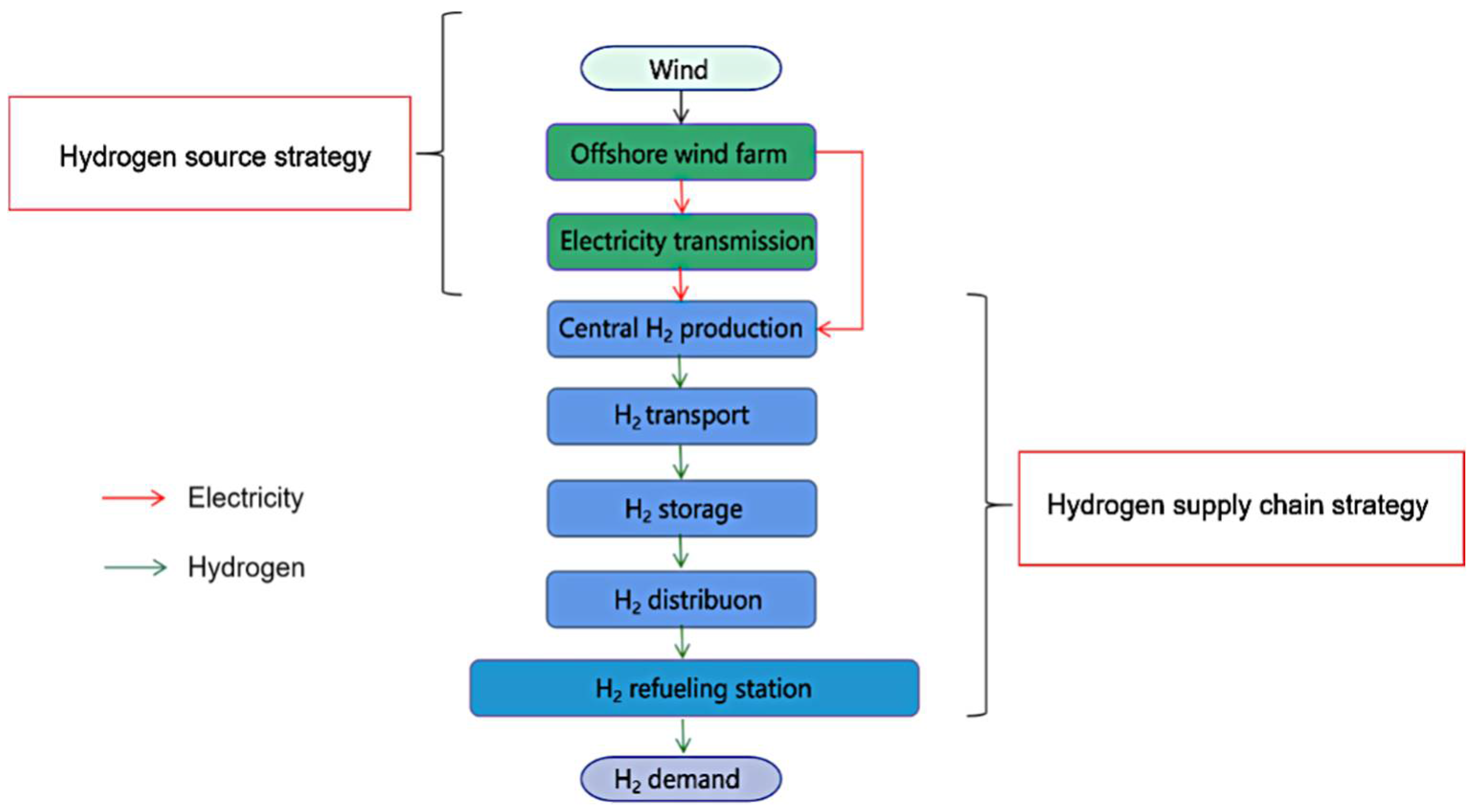
4]. Therefore, this paper is concerned the design of coastal expressway hydrogen supply chain network based on offshore wind power production of green hydrogen and the location of hydrogen refueling stations (HRSs). A discussion of the current situation and trend of hydrogen production, especially the research of hydrogen supply chain network based on wind power, is offered. Moreover, the paper reviews the main recent research topics related to the comprehensive review of hydrogen refueling station planning. The purpose is to find out the future development direction of green hydrogen and provide theoretical support for the planning and construction of hydrogen supply chain in coastal areas.

1.1. Current Situation and Trend of Hydrogen Production

There are a wide range of sources of hydrogen worldwide, especially the conversion of fossil energy to produce hydrogen, followed by pressure swing adsorption (PSA) purification and the recovery of industrial by-product hydrogen, as well as the electrolysis of water to produce hydrogen. Currently, of the 60 million tons of hydrogen produced annually in the world, about 96% of hydrogen comes from the reforming of fossil fuels, which indirectly causes a large amount of primary energy consumption and high emissions of greenhouse gases such as CO2 [5]. The remaining 4% of hydrogen is produced by electrolysis of water, and only hydrogen obtained by electrolysis using low-carbon electricity can be regarded as green hydrogen [6]. With the maturity of photovoltaic, wind, and other renewable energy technologies, the technology of generating hydrogen from renewable energy has been widely concerned in recent years, and research results and demonstration projects of hydrogen production from renewable energy are also emerging [7]. Hydrogen production by electrolysis of renewable energy can not only achieve a true zero-carbon hydrogen source, but also effectively solve the green electricity consumption problem caused by the intermittence of renewable energy. The randomness and volatility of renewable energy increase the uncertainty of power generation and demand, leading to the existence of a large number of abandoned wind and light phenomena. However, H2 could support the integration of renewable energy by redirecting abandoned energy sources, easing grid congestion and improving the reliability of systems in remote areas [8]. Tang et al. [9] presented a simple and transparent model for estimating the levelized cost of hydrogen (LCOH) to investigate the effect of solar photovoltaic, wind, and combining solar photovoltaic and wind as the renewable input, as well as the alternatives of on-grid and off-grid for hydrogen production. The results showed that using renewable energy to produce hydrogen can effectively reduce LCOH. To sum up, hydrogen production by electrolysis of renewable energy will gradually become the main trend of hydrogen production in the future [10].

1.2. Hydrogen Energy Supply Chain Based on Wind Power

Among the many renewable energy power generation technologies, wind energy is currently one of the most mature, large-scale, and most promising power generation methods for commercial development. On the one hand, available wind energy is widely distributed and abundant around the world; on the other hand, it has matured to be amongst the lowest cost variable renewable energy technologies: onshore wind projects have been developed with offtake agreements around 50–70 USD/MWh in the US, South Africa, and Europe [11]. At the same time, with the continuous maturity of wind power related technologies and equipment upgrading, the global wind power industry is developing rapidly, the wind power accounts for an increasing proportion in the global power production structure year by year [12]. At present, the total wind power generation accounts for about 5% of the global power generation [13]. China has become the world’s largest wind power market in terms of both accumulated installed capacity and newly installed capacity. Statistics in 2018 show that the total installed capacity of wind power in China accounts for about 32.76% of the world’s installed capacity [14]. Among them, according to the statistics of China Wind Energy Association, China’s offshore wind power installed capacity has maintained rapid development, with an average annual growth rate of more than 50% [
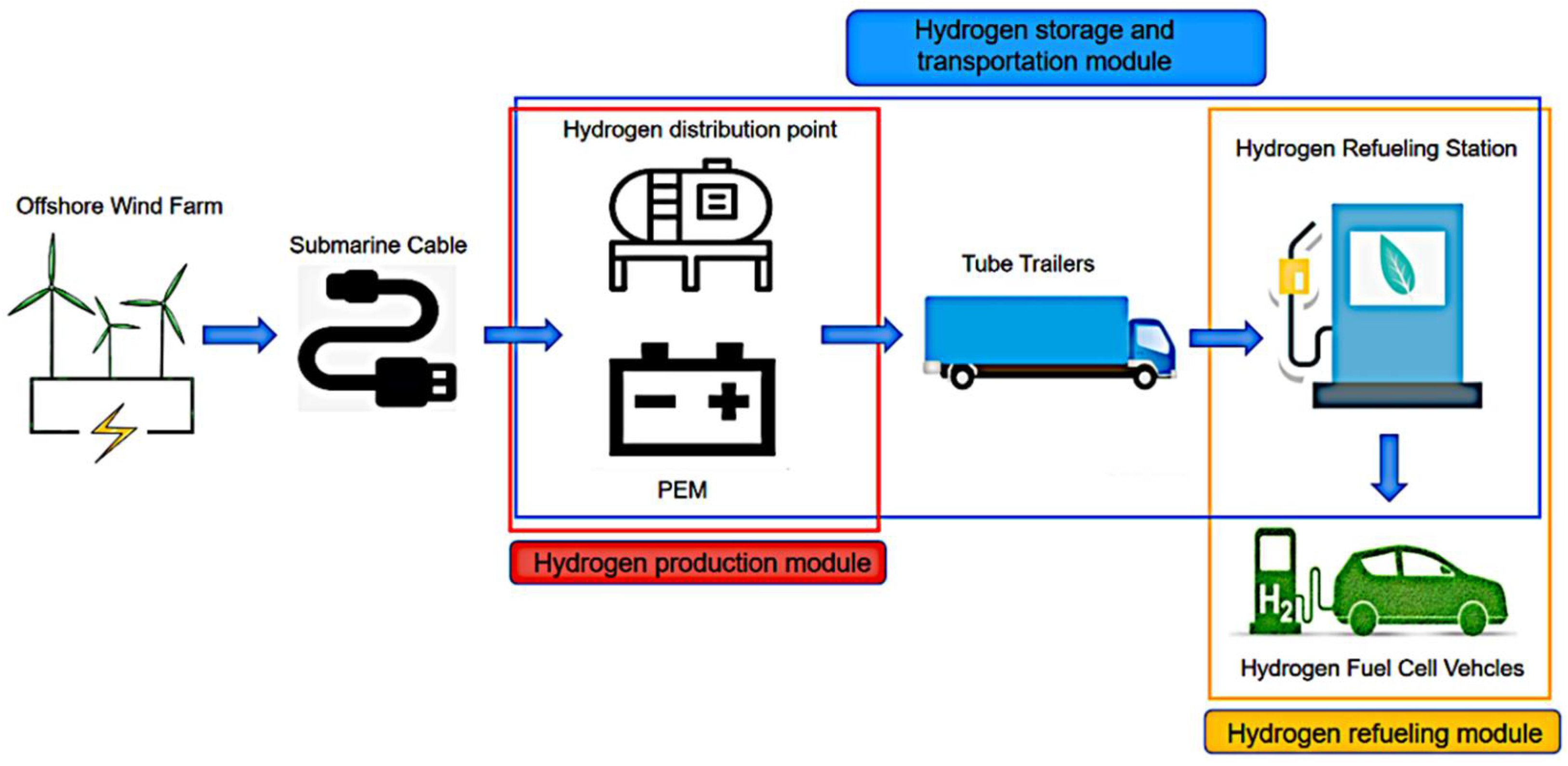
15]. As a form of renewable energy hydrogen production, with the continuous expansion of offshore wind farms, coastal areas can rely on abundant offshore wind power resources to produce green hydrogen and supply hydrogen fuel cell vehicles. Using the model of wind–electric–hydrogen–fuel cell vehicle can effectively promote energy conservation and emission reduction. Based on this point of view, Kim et al. [16] introduced an optimization method of hydrogen supply chain network planning relied on wind–hydrogen supply system and presented a case study related to system optimization design of Jeju Island, South Korea. Samsatli et al. [17] developed an optimization model and designed a combined wind–hydrogen–electricity network to decarbonize the transport sector in the United Kingdom. Taking a hydrogen refueling station located in Shanghai as an example, in order to evaluate the feasibility of using renewable hydrogen as fuel for HFCVS, Chen et al. [18] studied four low-carbon hydrogen energy supply routes. Among the Routes, Route 4 adopts the external hydrogen supply route that hydrogen is produced under the grid-connected photovoltaic and wind power generation mode of Qinghai Province and transported to Shanghai by liquid hydrogen truck. The results showed that Route 4 shows the best economic performance, both in hydrogen production stage and the whole hydrogen supply chain. Again, taking Shanghai as an example, Song et al. [19] proposed multi-hydrogen production methods and multi-transportation routes by studying and analyzing the internal and external hydrogen sources in Shanghai, and finally formed 12 hydrogen supply solutions according to local conditions. When the price of wind power drops to a certain value, offshore wind power and hydrogen networks will become Shanghai’s largest hydrogen supplier. For coastal areas, using offshore wind power to produce hydrogen can be a reliable source of hydrogen supply. Hydrogen fuel cell vehicles are currently the most efficient and easy-to-produce hydrogen energy application technology [20], and hydrogen refueling stations ensure the fuel supply of hydrogen fuel cell vehicles. Before the promotion of hydrogen energy vehicles, it is necessary to build a network of hydrogen refueling stations of a certain scale.

1.3. Comprehensive Review of Hydrogen Refueling Station Planning

It is estimated that by 2030, there will be 15 million hydrogen fuel cell vehicles and 15,000 hydrogen refueling stations in the world [21]. As of the end of 2020, about 553 hydrogen refueling stations have been built globally, and 107 new hydrogen refueling stations have been put into operation throughout the year. Among them, Germany, China, South Korea, and Japan lead the world in the construction of hydrogen refueling stations, adding 14, 18, 26, and 28, respectively, throughout the year [22]. As far as China is concerned, the number of hydrogen refueling stations completed at present is 127, of which 81 are in operation, 13 are internal experimental stations, 32 are to be operated, and 1 is suspended. Even though the construction of hydrogen refueling stations around the world is in full swing, the number of hydrogen refueling stations still fails to promote the hydrogen fuel cell vehicle industry [23]. On the contrary, the lagging hydrogen fuel cell vehicle industry restricts the development of hydrogenation infrastructure such as hydrogen refueling stations, so that hydrogen refueling stations still face many challenges [24]. In view of this, a reasonable site selection and layout of hydrogen refueling stations can not only make up for the lack of hydrogen energy utilization infrastructure, but also have certain practical significance for the country’s deployment of hydrogen energy networks. At present, many scholars have conducted studies on the location of hydrogenation infrastructure such as hydrogen refueling stations, and relevant studies are summarized in Table 1.
Starting from hydrogen demand in network nodes, some scholars combined with classic location problems, including coverage problem [25] and p-median (or center) problem [26], to site hydrogen refueling stations and other facilities. Frade et al. [27] applied the set covering problem (SCP) of point demand to study the location of hydrogen refueling stations, and the proposed model was implemented in Lisbon and the location scheme was evaluated. Hajari et al. [28] proposed a two-step modeling and solution of the maximal covering location problem (MCLP), in which demand can be distributed in every corner of the road network. They solved the problem of optimal resource allocation in downtown Pittsburgh by using both precise algorithm and heuristic algorithm. Liu et al. [29] established a p-median model considering reliability and cost constraints by analyzing queuing theory, route accessibility, cost constraints, and other factors in the study of location selection of electric taxi charging stations, and tested and solved optimal schemes under different reliability conditions under classical calculation examples. Nicholas et al. [30] combined the p-median model with geographic information system and applied it to the location of hydrogen refueling stations in California. Tatjana et al. [31] applied the colony optimization algorithm to the p-center model containing the symmetric distance matrix.
Different from the above classical location problems, some scholars determined location for hydrogen refueling stations and other facilities based on the flow demand of road network. Corresponding models include flow-capturing location model (FCLM) [32] and flow-refueling location model (FRLM) [33]. Hodgson et al. [34] combined the FCLM with the greedy algorithm to locate the site of the hydrogen refueling stations in Edmonton, Canada. To obtain the relationship between the sales of hydrogen fuel vehicles and the number of hydrogen refueling stations, Li et al. [35] combined the generalized bass diffusion model with the FCLM. To optimize the location of hydrogen refueling stations, they solved the integrated optimization model by using the capacity constrained FCLM algorithm and the solution process was designed. Kuby et al. [36] referred to the actual road network data of Florida in the United States and optimized and solved the location problem of hydrogen refueling stations in the road network, in order to test the feasibility of the FRLM in the actual location study. Upchurch et al. [37] compared the solving effects of p-median model and FRLM in solving the location problem of mixed fuel stations, proving that FRLM is more suitable for solving the location planning problem of service facilities with refueling capacity constraints.
Different from the location model that considers point demand and flow demand, some scholars built a comprehensive mathematical location model for hydrogen refueling stations by combining many factors in hydrogen production and application. Onur et al. [38] established a mathematical programming model and integrated the production, storage and transportation, security, location, and personnel allocation decisions, considering the cost minimization. The results show that the proposed model can effectively solve the problem of cover all areas. Li et al. [39] focused on establishing a mathematical model covering the entire hydrogen supply network, combined the classic hydrogen supply chain network design model with the hydrogen refueling stations’ location planning model, and took a certain region in France as an example to demonstrate the feasibility of the model. Sungmi et al. [40] proposed an optimization model and took the adoption of hydrogen fuel cell vehicles in Seoul by 2030 as the goal; they analyzed various scenarios of hydrogen supply network design parameters. The optimization model can be effectively used to determine the construction time and location of hydrogen production base and hydrogen refueling station. Miralinaghi et al. [41,42] optimized the layout of hydrogen refueling stations by reducing the construction cost of hydrogen refueling station network and the time cost of vehicles used for hydrogenation.
It is not difficult to see that the studies on planning layout and construction of hydrogen refueling stations in the above literature are all concentrated in a certain city or region, while there are few studies on location of hydrogen refueling stations with expressways as the background. To some extent, relatively mature charging stations have certain reference significance for the location research of expressway hydrogen refueling stations. Compared with the hydrogen fuel cell vehicle industry, the electric vehicle industry is relatively mature, and there are abundant literatures on expressway charging stations. Pevec et al. [43] studied the charging stations problem of FCLM on expressways. In his model, the nodes on the expressway were classified, the entrances and exits were set up by default, and the service area was taken as the alternative center for station construction. Finally, a real expressway network was used to verify the effectiveness of the model and algorithm. Hoon et al. [44] transformed the flow demand problem into the combinatorial optimization problem of the passage in the path section by putting forward the assumption of the passage between nodes. Based on this, they constructed the combinatorial optimization model of the coverage of the path section of the charging station and applied it to solve the multi-stage location optimization problem of the charging station in South Korea. For the study of expressway hydrogen refueling stations, Zhao et al. [45] introduced a modeling framework of hydrogen refueling stations system positioning based on path, multi-scale, and scene planning. The method was based on the FRLM and the expressway traffic flow capture method to better conduct detailed geographical optimization of this multi-scale location planning problem. Sun et al. [46] realized the planning layout of Hu-Ning expressway hydrogen refueling station from Shanghai to Nanjing in China relied on the life cycle cost of hydrogen supply chain. In his model, multi-source hydrogen supply and life cycle cost were taken into account, and the locations of five hydrogen refueling stations on the expressway were ultimately determined. Hamidreza et al. [47] studied the distribution of hydrogen supply chain network in Canada’s hydrogen corridor. Through the research, Hamidreza discussed the layout and distribution of hydrogen supply chain network in five scenarios under different market share rates of hydrogen fuel cell vehicles. Among the scenarios, in the case that hydrogen fuel cell vehicles account for 5% of the market, the cost per unit of hydrogen used in the hydrogen supply chain network of the whole section is 14.7 USD/kgH2.

1.4. Research Motivation

In the early stage of hydrogen fuel cell vehicle penetration into the market, the construction of infrastructure such as hydrogen refueling station is very important [47]. For hydrogen fuel cell vehicle to be accepted by the public, on the one hand, supporting infrastructure such as hydrogen refueling station needs to be followed up, and on the other hand, hydrogen energy road network needs to be improved, and the construction of hydrogen energy road network needs to start from the hydrogen expressway. As the inter-city traffic fortress, the expressway network is indispensable, and it is not hard to see from the above-mentioned literature on hydrogen refueling station locations that the current research on expressway hydrogen refueling stations is still very scarce. Regardless of whether it is from the view of point demand, starting from the flow demand model or constructing a comprehensive mathematical location model of hydrogen refueling station, most scholars mainly focus on a certain area or a certain city within the scope of the hydrogen refueling station and other infrastructure location, and the model is not universal. Although the location of hydrogen refueling stations on expressways can refer to the research on the site selection of charging stations to some extent, due to the essential differences in energy types and charging methods [48], the location of hydrogen refueling stations, especially because of the coastal expressway hydrogen source is based on offshore wind power generation, which still has far-reaching significance and practical application value. In addition, considering the geographical characteristics of coastal areas and the types of hydrogen sources, the research on the scientific layout of hydrogen refueling stations on coastal hydrogen expressways is innovative.

1.5. Content and Research Contributions

This paper relies on the increasingly mature and fast-developing offshore wind power as a reliable source of green hydrogen. On the basis of hydrogen expressway construction in coastal areas, we establish a general comprehensive mathematical location model for hydrogen refueling stations on expressways and conduct scientific site location for hydrogen refueling stations on hydrogen energy expressways along the coast. Specifically, the paper combines the design of hydrogen supply chain networks in coastal areas with the location of hydrogen refueling stations on expressways. The model aims at minimizing the cost of hydrogen use in the hydrogen supply chain network and fully considers factors such as road section hydrogen demand, hydrogen production, hydrogen storage and transportation, and hydrogen refueling station refueling methods. The hydrogen cost of each link in the hydrogen supply chain is used as the model input. The hydrogen demand of the road section limits the scale and number of hydrogen refueling stations, and the mileage of hydrogen fuel cell vehicles restricts the station distance of hydrogen refueling stations. Finally, with the help of optimization algorithm, the optimal location of hydrogen refueling stations on coastal hydrogen energy expressways can be determined, and the carbon emission factor method [49] can be used to calculate the carbon emission reduction potential of the hydrogen supply chain network. Then, the northeast, east, and southeast coastal areas of China are selected as examples of coastal hydrogen energy expressways for the layout of hydrogen refueling stations along the route, and carbon emission reduction calculations are carried out on the hydrogen production and application sides of the hydrogen supply chain network of each case section.
The contribution of the article is mainly that the constructed model can be used to help a certain expressway network in a certain area to transform a traditional car into a hydrogen fuel cell vehicle in the early transition plan. It could propose a solution for the infrastructure dilemma caused by the initial use of hydrogen as a fuel in the general market. Feasible solutions provide impetus for economic transformation and carbon emission reduction in coastal areas and at the same time have certain guiding significance for promoting the development of the hydrogen energy industry.

2. Methodology

2.1. Model Modeling Concept

The supply of hydrogen can be divided into two stages: from hydrogen source to hydrogen refueling station and from hydrogen refueling station to consumer. Whether it is a location model starting from point demand or starting from flow demand, the model starts from the hydrogen refueling station to the consumer stage, and the consideration is to minimize the hydrogen refueling distance or maximize the service volume of the hydrogen refueling station. At the stage from the hydrogen source to the hydrogen refueling station, it is necessary to fully consider many factors, such as the hydrogen production, storage and transportation, and the refueling method of the hydrogen refueling station, because these factors will affect the economical layout of the hydrogen refueling station. Therefore, in order to improve the economics of planning layout about hydrogen refueling station, this paper incorporates optimization of the stage of hydrogen from hydrogen source to hydrogen refueling station. Combining the hydrogen supply chain network design with the site selection of hydrogen refueling stations on expressways, the model aims to develop a mathematical method that fully considers hydrogen production technology, storage and transportation methods, and refueling methods of hydrogen refueling stations. With the goal of minimizing the total cost of the hydrogen supply chain network in the expressway section, it is used for the main deployment of hydrogen refueling stations along the expressway, including the size and location of the hydrogen refueling stations.

2.2. Hydrogen Energy Chain for Coastal Areas

Coastal areas are rich in offshore wind power resources. Relying on offshore wind power, can produce clean, low-carbon, and reliable green hydrogen to supply hydrogen to hydrogen refueling stations on hydrogen expressways in coastal areas, thus constructing a complete expressway hydrogen supply chain network.
Figure 1 summarizes the entire process of offshore wind power production and hydrogen supply in the coastal expressway hydrogen supply chain network. Wind energy supply chain process as follows. Coastal wind resources are converted into green electricity through offshore wind farms, and the generated electricity is directly used for hydrogen production by electrolysis or transported to central hydrogen production facilities for hydrogen production. Hydrogen supply chain process considers the typical hydrogen production, storage and transportation, and hydrogen refueling station refueling process. Since the model only considers the stage of hydrogen from the hydrogen source to the hydrogen refueling station, the cost of the offshore wind power generation process is not considered in the model. The model construction starts from the hydrogen supply chain process and is mainly divided into three parts about hydrogen production, storage and transportation, and refueling. This consideration makes the model applicable to different sources of hydrogen and is more universal.

2.3. Modeling of Hydrogen Refueling Station Location Factors

From the above description, the hydrogen supply chain process mainly includes three parts: hydrogen production, hydrogen storage and transportation, and hydrogen refueling station filing. Each part involves different applicable conditions and technical methods. For example, the hydrogen production process can use traditional fossil energy reforming to produce hydrogen or renewable energy power generation and electrolysis to produce hydrogen. The storage and transportation process of hydrogen can use high-pressure gaseous hydrogen storage and transportation or low-temperature liquid storage and transportation [50,51], etc. There are also two types of refueling methods for hydrogen refueling stations: 35 MPa and 70 MPa, which are currently commonly used in China. These factors can be selected according to the specific application scenarios of hydrogen energy, and different choices and combinations will affect the final hydrogen cost of the hydrogen supply chain network. Therefore, the model starts from the total cost of hydrogen in the hydrogen supply chain network of the expressway and divides the total cost C of hydrogen in the hydrogen supply chain network into three aspects: the production cost of hydrogen C P , the storage and transportation cost of hydrogen C S T , and the cost of hydrogen refueling station C H . The specific expression is shown in Formula (1):
C = C P + C S T + C H
The application scenarios and technical methods of different components will be used as the key input of the corresponding part of the cost. The relevant expressions are analyzed as follows:
1.
The production cost of hydrogen C P
In order to understand the approximate cost of hydrogen production and to understand the markets in which hydrogen is competitive, the measurement of LCOH is critical [52]. Many papers have discussed the approach of calculation of LOCH and NPV (the net present value) [52,53,54,55]. The determination of LCOH is performed following Equation (2).
LCOH = t   =   1 n I t   +   M t   +   F t 1   +   r t t   =   1 n E t 1   +   r t
where t stands for the year; r and n are the discount rate and the lifetime of the project, respectively; I t is the expenditures in year t ; M t stands for the OPEX and the adjusted share of the decommissioning costs in year t ; F t is the expense relative to the electricity costs; and E t refers to the total hydrogen production in year t .
In this paper, the production cost of hydrogen is related to the capacity of the hydrogen source, the technology of hydrogen production, and the daily refueling capacity of hydrogen refueling station. Different production technologies have different cost-economic indicators. The hydrogen production analysis model (H2A) developed by the National Renewable Energy Laboratory [56] can take the economic indicators of different production technologies as input. In this model, the LOCH of the hydrogen supply chain network is included in the calculation process of the H2A, and the corresponding unit hydrogen production cost is calculated, combined with the design scale of the hydrogen refueling station, so the hydrogen production cost can be obtained, as shown in Formula (3):
C P = i N j M p j × w i j
where i and j are the indexes of hydrogen refueling station and hydrogen source, respectively; N and M are the sets of hydrogen refueling station and hydrogen source, respectively; C P is the production cost of hydrogen; p j is the unit cost of hydrogen production of hydrogen source j (USD/kgH2); and w i j   is the mass of hydrogen supplied by hydrogen source j to hydrogen refueling station i (kg).
2.
The storage and transportation cost of hydrogen C S T
The cost of hydrogen storage and transportation is directly related to its storage and transportation method, transportation distance, and refueling capacity of station. Similar to the above-mentioned hydrogen production cost, different transportation methods have different cost-economic indicators, which are used as the key input of the calculation model. The expression of cost about hydrogen storage and transportation in the model is shown in Formula (4):
  C S T = i N j M c i j × w i j
where C S T is the cost of hydrogen storage and transportation, c i j is the unit cost about storage and transportation of hydrogen source j to hydrogen refueling station i (USD/kgH2), and the specific result of c i j is based on the distance d i j between hydrogen source j and hydrogen refueling station i (km), the cost index of transportation is   A [57,58], and the cost index B of hydrogen storage and transportation is obtained through the hydrogen distribution scenario analysis model (HDSAM) [59] that is combined with the input of the economic indicators of the corresponding transportation mode. See Formulas (5)–(7):
c i j = A × d i j + B
A = f p × 2 l e n g t h m p g / l h
d i j = x i x j + d
where f p is the unit price of the fuel used by the vehicle (USD/L), l e n g t h is the length of the transport path (km), m p g is the fuel economy of the transport, l h is the hydrogen carrying capacity of the transport (kg), x i is the plus coordinates x i ,   y i corresponding to hydrogen station i , x j is the transport node coordinates x j ,   y j corresponding to hydrogen source j , and d is the distance between the transport node and hydrogen source j (km).
3.
The cost of hydrogen refueling station C H
The cost about hydrogen refueling station is related to the refueling pressure, hydrogen refueling efficiency, hydrogen refueling capacity, and other factors. Through the hydrogen distribution scenario analysis model, combined with the key parameters of hydrogen refueling station’ refueling pressure, efficiency, etc., the hydrogen refueling station cost per unit hydrogen can be obtained. The expression is shown in Formula (8):
C H = i N j M c h i × w i j
where C H is the cost about hydrogen refueling station, and c h i is the unit hydrogen refueling station cost (USD/kgH2).

2.4. Location Model of Expressway Hydrogen Refueling Station

Combining the hydrogen refueling station location factor modules modeled by the above parts, with the goal of minimizing the total cost of hydrogen used in the hydrogen supply chain of the entire road section, a comprehensive mathematical model of expressway hydrogen refueling station location is obtained as follows:
Minimize   C = i N j M p j × w i j + i N j M A × d i j + B × w i j + i N j M c h i × w i j
Constraint conditions:
i N w i j L j
j M w i j w i
i N w i D
j M L j i N w i
d i , i + 1 200
where L j is the daily maximum production capacity of hydrogen source j (kgH2/d), w i is the daily refueling capacity of hydrogen refueling station i (kgH2/d), D is the total hydrogen demand of expressway section (kgH2/d), and d i , i + 1 is the distance between adjacent hydrogen refueling stations.
Among the constraints, Constraint (10) ensures that the hydrogen demand of each station from the same hydrogen source does not exceed the maximum capacity of the hydrogen source. Constraint (11) ensures that the hydrogen purchase of each station from different hydrogen sources does not exceed its own capacity. Constraint (12) ensures that the capacity of all hydrogen refueling stations meets the total hydrogen demand of the road section. Constraint (13) ensures that the capacity of all hydrogen refueling stations does not exceed the capacity of all hydrogen sources. According to the cruising range of hydrogen fuel cell vehicles, Constraint (14) limits the maximum distance between two adjacent stations cannot exceed 200 km. In general, the constraint on hydrogen demand restricts the scale and number of hydrogen refueling stations in the whole section. The limitation of the mileage of hydrogen fuel cell vehicles restricts the construction distance of each hydrogen refueling station in the section of the road and then determines the location of hydrogen refueling station, while ensuring the full coverage of the hydrogen supply of the road section and the convenience of hydrogenation behavior.

2.5. Location Model Assumptions and Applicable Conditions

Based on the construction of the above comprehensive mathematical model for site selection, the assumptions and applicable conditions are explained as follows. (1) The expressway is directional and irreversible in one direction. (2) When the driver misses a hydrogen refueling station, he needs to drive to the next station to complete the refueling behavior. (3) When hydrogen fuel cell vehicles perform hydrogenation, the hydrogen capacity should not be less than 50%; that is, the distance between adjacent hydrogen refueling stations should not be more than half of the mileage of hydrogen fuel cell vehicles. In this paper, the hydrogen fuel cell vehicle takes the Chinese domestic brand Roewe 950 as an example, and its cruising range refers to the data in Table 2. (4) Averages the traffic volume and hydrogen demand per kilometer of the road section. (5) Does not consider seasonal and hourly hydrogen demand and changes in hydrogen supply. (6) The influence of geographical climate and weather factors on the design and construction of hydrogen supply chain network is not considered. (7) The model is suitable for the initial stage of hydrogen expressway network construction. (8) The hydrogen production method, storage and transportation technology, and hydrogen refueling station filling method can be adjusted according to the actual optimization situation.
The comprehensive mathematical model for the location of hydrogen refueling stations on the expressway takes into account the overall optimization factors in the hydrogen supply chain network and reduces the actual variables as much as possible, thus reducing the difficulty of the solution. Finally, the MATLAB calculation tool is used, and the particle swarm algorithm (PSO) is used to optimize the solution. In addition, although the location model developed in this paper is applied to the case of coastal hydrogen expressway hydrogen refueling station selection based on hydrogen production from offshore wind power as hydrogen source, this model is also applicable to inland areas and other scenarios of hydrogen supply mode, as only corresponding parameters need to be changed. The model can adjust the key parameters of the input model in combination with specific application scenarios and hydrogen production and storage and transportation technology. Therefore, it can be applied to the location of expressway hydrogen refueling stations under different conditions and has certain applicability.

2.6. Carbon Emission Reduction Estimation

The use of offshore wind energy resources to generate hydrogen can greatly reduce the emission of CO2 and other greenhouse gases from the hydrogen production side. The application of green hydrogen in hydrogen fuel cell vehicles can greatly reduce the use of fossil energy such as gasoline in the transportation field, thereby reducing CO2 emission and achieve emission reduction [60]. As for the research on the relationship between renewable energy production and use of hydrogen and carbon emissions from the process, Silvestri et al. [61] did the following work: they proposed an incentive strategy based on the economic valorization of the avoided CO2 eq resulting from the proposed hydrogen pathway in comparison to the gasoline one to ensure that the economic sustainability of the on-site hydrogen refueling stations powered by grid-connected solar plants. Similarly, different from the mode of using photovoltaic field hydrogen production and supply hydrogen refueling station, and in order to explore the positive impact of hydrogen production from offshore wind power and hydrogen energy utilization on the environment, in addition to considering the hydrogen cost of the expressway hydrogen supply chain network, the carbon emission reduction analysis of the hydrogen production and application sides in the hydrogen supply chain network was also introduced into the calculations in this paper. The carbon emission factor method is used for calculation, and the specific formula is as follows:
E C O 2 = M f × E F f , C O 2
where E C O 2 is the CO2 emission (kg), M f is the fuel consumption (kg), and E F f , C O 2 is the CO2 emission factor of the consumed fuel. The carbon emission factors of different fuels can be inquired through the “2006 IPCC National Greenhouse Gas Inventory Guidelines” and “China Energy Statistics Yearbook 2019” issued by the National Bureau of Statistics of China [62,63].
Regarding the carbon emission calculation of the hydrogen production side, the electricity consumed by the electrolysis of offshore wind power to produce unit hydrogen is converted into the equivalent amount of electricity produced by traditional fossil fuels. The specific formula is as given in Formula (16):
M C = M H × p H × m C
where M C is the mass of standard coal consumed by traditional thermal power generation (kg), M H is the amount of hydrogen produced by offshore wind power (kg), p H is the wind power consumed per unit of hydrogen production (kWh/kgH2), and m C is the standard coal mass consumed per unit of electricity production (0.1229 kg/kWh). Therefore, Formula (15) is used to calculate the CO2 released by the application of traditional fossil fuels under the same amount of electricity, and in contrast, the CO2 emission reduction of hydrogen production through the electrolysis of offshore wind power can be understood.
For the carbon emission measurement of the hydrogen application side, the hydrogen demand on the road section is converted into the gasoline demand through the conversion of the calorific value of hydrogen fuel and gasoline [64], the specific formula is as given in Formula (17). Furthermore, according to the carbon emission factor of gasoline, combined with Formula (15), the CO2 emission reduction at the hydrogen application side is calculated.
M G = M H × L H V H L H V G
where M G is the mass of gasoline (kg), L H V H is the lower heating value of hydrogen (119.9 MJ/kg [65]), and L H V G is the lower heating value of gasoline (43.4 MJ/kg [66]).
Based on Formulas (15)–(17), carbon emission reduction can be calculated for the hydrogen production side and the road section application side of the expressway hydrogen supply chain network. The process of hydrogen storage and transportation, whether it is transporting hydrogen in long tube trailers or storing hydrogen in hydrogen storage tanks, is a process of energy consumption and increased carbon emissions. This chapter discusses the reduction of CO2 emissions by hydrogen energy utilization. Therefore, the hydrogen storage and transportation process of the hydrogen supply chain network does not consider and calculate carbon emission reduction.

3. Method and Model Validation

The validation of model selects the China Shanghai-Nanjing Expressway section in the literature [46] and combines the hydrogen refueling station location comprehensive mathematical model constructed to carry out the hydrogen refueling station layout. It compares the cost results with the results of 14.7 USD/kgH2 per unit hydrogen cost in the case of the 5% hydrogen fuel cell vehicle market share in the hydrogen supply chain network of the whole road section in the literature [47]. The results are compared to verify the effectiveness of the constructed location model, and finally the carbon emissions of the hydrogen supply chain network are calculated. The model calculation framework is shown in Figure 2. The model uses the statistical data of expressway sections and the economic parameters involved in hydrogen supply chain process as input. It combines with the hydrogen demand and station construction distance that affect the layout of hydrogen refueling stations, the hydrogen refueling stations along the expressway are optimized with the help of MATLAB and optimization algorithms, and finally the hydrogen refueling station layout plan is obtained. At the same time, the carbon emission factor method is used to calculate carbon emission reductions on the hydrogen production side and application side of the hydrogen supply chain network.

3.1. Expressway Model Verification Input

The Shanghai-Nanjing Expressway has a total length of 274 km and has six service areas in total. The service area has gas station locations that can be used as candidate locations for hydrogen refueling stations [67]. Taking Shanghai, the starting point of Shanghai-Nanjing Expressway, as the origin of the coordinates. We take the “straightened” direction from Shanghai to Nanjing as the positive direction of the x-axis and rotate the x-axis 90 degrees clockwise as the positive direction of the y-axis to establish a coordinate system [46]. Thus, the hydrogen source and the location of the hydrogen refueling station can be expressed in coordinate form. The by-product hydrogen of the chlor-alkali industry can be used as a low-cost hydrogen production method. The hydrogen production cost of large-scale advanced chlor-alkali plants can be controlled within the range of 2.5 USD/kgH2 [68], so chlor-alkali companies along the Shanghai-Nanjing Expressway are selected as reliable sources of hydrogen. The condition of the road section and the distribution of service areas and hydrogen sources are shown in Figure 3.
Based on the research content and optimized scene data of reference [47], assuming that the market share of hydrogen fuel cell vehicles reaches 5%, the hydrogen demand for road sections is calculated based on the Chinese domestic hydrogen fuel cell vehicle Roewe 950 [69]. Other propulsion systems are not considered in this calculation. High-pressure hydrogen transportation is the current main method of hydrogen transportation [50]. The HDSAM model can estimate the cost of hydrogen storage and transportation and the cost of hydrogen refueling stations with different capacities (500 kgH2/d, 800 kgH2/d, and 1000 kgH2/d). Combining the relevant data from the literature [46], as the key input of the model, the hydrogen demand, the location of the hydrogen source, and the cost information of each part of the hydrogen supply chain are summarized in Table 3 and Table 4.

3.2. Expressway Model Verification Results and Analysis

In order to meet the hydrogen demand of the road section, the Shanghai-Nanjing expressway hydrogen supply chain network is divided into two optimization scenarios. One is single hydrogen source hydrogen supply, with single hydrogen refueling station capacity. The other is dual hydrogen source hydrogen supply, with multiple hydrogen refueling station capacity. Combining the above key parameters input, the calculation of the model is realized by the optimization algorithm. In the two scenarios, four and five stations are optimized, respectively. The specific distribution of hydrogen refueling stations is shown in Figure 4, and the calculation results are shown in Table 5.
From the calculation results of the above location and the schematic diagram of the hydrogen refueling station layout, it is not difficult to see that in the two scenarios, the road sections are optimized to build four and five stations, respectively. In scenario 1, the hydrogen supply chain network of the road section is supplied by hydrogen source 1, and the optimized hydrogen refueling stations are more evenly distributed throughout the expressway section. Among them, stations 3 and 4 are located close to the service area, and the service area has been previously used as a candidate site to be built. Therefore, it is possible to consider arranging stations 3 and 4 in existing service areas to improve land utilization and reduce costs. In scenario 2, the hydrogen supply chain network of the road section supplies hydrogen from two hydrogen sources, hydrogen source 1 and hydrogen source 2, where stations 1–2 are supplied by hydrogen source 1, and stations 3–5 are supplied by hydrogen source 2. The optimized hydrogen refueling station better covers the entire expressway. Similar to scenario 1, stations 3 and 4 can also be directly deployed in existing service areas. In addition, in the two scenarios, the unit hydrogen cost of the hydrogen supply chain network is 15.8 USD/kgH2 and 13.3 USD/kgH2, respectively, which is the same as the cost per unit of hydrogen (14.7 USD/kgH2) in the hydrogen supply chain network in the hydrogen corridor under the condition that the market share of hydrogen fuel cell vehicles is 5% in literature [47]. The relative errors are 7.5% and 9.5%, respectively.
Since the hydrogen source used in the selected expressway section is hydrogen by-product from the chlor-alkali industry, this process cannot achieve zero emissions from the hydrogen source. Therefore, the carbon emission reduction calculation of the hydrogen supply chain network only considers the hydrogen application side. Combining Formulas (15)–(17), it is calculated that the daily CO2 emissions that can be reduced by the hydrogen application side of the Shanghai-Nanjing Expressway is 17.0 tons, the CO2 emissions per unit mileage of the expressway section can be reduced by 62.04 kgCO2/km, and the unit hydrogen demand can reduce the CO2 emissions is 6.34 kgCO2/kgH2.
Based on the verification results of the above case, the comprehensive mathematical location model for expressway hydrogen refueling station constructed in this paper can be used as an effective method for studying the location of hydrogen refueling station and carbon emission reduction calculation.

4. Hydrogen Refueling Station Layout along the Coast Expressway

China’s long and narrow coastline and abundant offshore wind power resources provide ample hydrogen source guarantee for the construction of hydrogen refueling stations. At the same time, the coastal areas are the most prosperous and active areas of China’s economy, as well as the most complete areas of China’s modern integrated transportation system, and it is also the most urgent area in China for energy conservation, emission reduction, and transformation of economic development mode [70]. Therefore, relying on the increasingly mature offshore wind power industry to produce green hydrogen, promoting the demonstration construction of hydrogen expressways in coastal areas and the scientific layout of hydrogen refueling stations along the route will play a positive role in the development of hydrogen energy for the coastal areas and the popularization of hydrogen fuel cell vehicles.

4.1. Case Description of Coastal Expressways

Several expressways in the northeast, east, and southeast coastal areas of China are selected as hydrogen refueling station optimization cases. They are the Dalian-Dandong section of the He-Da Expressway, and the Dalian-Yingkou section, the Jiangsu section, and the Guangdong section of the Shen-Hai Expressway, respectively. The specific distribution of the case expressways in the coastal areas of China is shown in Figure 5. Combining the mathematical model of hydrogen refueling station site selection and the main input parameters of each part of the hydrogen supply chain network in this study, the key description is given. In the case, the site selection and layout optimization of hydrogen refueling stations along the expressway are carried out, and carbon emission reduction calculations are carried out on the hydrogen production and application aspects of the hydrogen supply chain network.
The technical route of the hydrogen energy industry chain in coastal areas is shown in Figure 6. Offshore wind power is transmitted to hydrogen energy distribution points via submarine cables, and hydrogen is produced by hydrogen production using proton exchange membrane electrolyzed water (PEM). The PEM uses a solid proton exchange membrane to replace the liquid electrolyte and diaphragm in the traditional alkaline electrolysis of hydrogen (AWE) technology. It can separate hydrogen and oxygen, ensure the purity of the product, and have current density large, high electrolysis efficiency, no pollution, dense structure, small size, etc. The PEM also can quickly change load, short response time, and good matching with photovoltaic and wind power (the randomness and volatility of power generation) [71]. As an important link between offshore wind power facilities and onshore hydrogen production facilities, hydrogen distribution points assume the role of indirect hydrogen source and also the starting point of hydrogen transportation. The hydrogen produced by the hydrogen energy distribution point is transported to the hydrogen refueling station in a high-pressure gaseous state through a long tube trailer [50] for the refueling of hydrogen fuel cell vehicles. Therefore, the hydrogen supply chain in coastal areas that relies on offshore wind power starts with hydrogen production at the hydrogen energy distribution point and ends with the refueling and use of hydrogen fuel cell vehicles. The relevant calculations of the model also start from the hydrogen production of the hydrogen energy distribution point.

4.2. Hydrogen Demand Estimation for Coastal Expressway Sections

As a key input, the estimation of hydrogen demand is an important part of the preparatory work for the location optimization of hydrogen refueling stations. The estimation of hydrogen demand mainly depends on key parameters such as the daily average vehicle mileage per kilometer of expressways, fuel economy, and market share of hydrogen fuel cell vehicles. According to data from the Ministry of Transport, in 2019, the total mileage of national expressways was 149,600 km, the annual average daily traffic flow of national expressways was 27,936, and the annual average daily driving volume was 1,478.26 million veh.km. The average daily vehicle mileage per kilometer reached 9,881.4 veh.km/km/d [72]. According to forecasts by authoritative organizations, by 2030, the sales of fuel cell vehicles in the commercial vehicle and passenger vehicle sectors are expected to account for 7% and 3%, respectively [73]. Therefore, the cases of this paper take 2030 as the time node, assuming that the average daily vehicle mileage per kilometer of expressway will reach 20,000 veh.km/km/d, and the market share of hydrogen fuel cell vehicles will reach 5% (consolidated as passenger cars). Taking China’s domestic hydrogen fuel cell vehicle Roewe 950 as the standard, the main parameters of the coastal hydrogen expressway sections in each case are summarized in the Table 6.
According to the above parameters, hydrogen fuel cell vehicles consume 194 kg/km/d of hydrogen per kilometer. Based on the market share of hydrogen fuel cell vehicles and the total mileage of the road section, the hydrogen demand for the entire road section is estimated, respectively. The total hydrogen demand for the Dalian-Dandong section is 2930 kg/d. The total hydrogen demand for the Dalian-Yingkou section is 2368 kg/d. The total hydrogen demand for the Jiangsu section is 3605 kg/d. The total hydrogen demand for the Guangdong section is 1883 kg/d.

4.3. Hydrogen Production Cost

To evaluate the unit production cost of hydrogen, the case used the H2A model developed by the National Renewable Energy Laboratory [56]. Taking the centralized PEM electrolyzed water with a daily hydrogen production of 5000 kg as an example to calculate the per unit production cost of hydrogen. The relevant information of the PEM electrolyzer and the calculation results of per unit hydrogen production cost are shown in Table 7. The method, scale, and cost of hydrogen production from hydrogen sources of various coastal hydrogen expressways are all based on Table 7.

4.4. Hydrogen Storage, Transportation, and Hydrogen Refueling Station Cost

Based on the HDSAM model developed by the Argonne National Laboratory, the cost of hydrogen storage and transportation and the cost of hydrogen refueling stations are estimated [59]. It is worth noting that the storage and transportation cost of hydrogen is not a fixed value but is related to the distance between the hydrogen source and the hydrogen refueling station and the fuel economy indicators of the transportation vehicle. In short distances, long-tube trailer high-pressure gas hydrogen transportation is economical. At present and in the future, China’s domestic hydrogen refueling stations will still be mainly 35 MPa. Therefore, consider the long-tube trailer high-pressure gas hydrogen transportation, gas hydrogen cascade storage, and hydrogen refueling station refueling pressure of 35 MPa as the key inputs and assumptions of the scenario. The relevant parameters are summarized in Table 8. The hydrogen storage and transportation cost and hydrogen refueling station cost of the hydrogen supply chain network of the coastal hydrogen energy expressways in the cases are calculated. The daily hydrogen refueling capacity of the hydrogen refueling station is 500 kgH2/d, 800 kgH2/d, and 1000 kgH2/d, the calculation results are summarized in Table 9.

4.5. Optimize Scenario Definition

Under the premise of meeting hydrogen demand, the coastal hydrogen expressways to be optimized are divided into single hydrogen source hydrogen supply, with single-capacity hydrogen station, and dual hydrogen source hydrogen supply, with multi-capacity hydrogen station. The two optimization scenarios are respectively optimized. The hydrogen production scale of hydrogen energy distribution point (hydrogen source) is 5000 kgH2/d. The service area along the expressway serves as a potential site for hydrogen refueling stations, and the specific distribution of road sections, hydrogen energy distribution points, and service areas. In Figure 7, panels (1)–(4) respectively show the Dalian-Dandong section and the Dalian-Yingkou section in the northeastern coastal region of China, the Jiangsu section in the eastern coastal region, and the Guangdong section in the southeastern coastal region. Dalian, Lianyungang, and Shantou are taken as the starting point to construct the coordinate system. Table 10 summaries the specific distribution locations of hydrogen distribution points available in the cases.

4.6. Optimization Procedure

According to the mathematical model of this article, the site selection of a hydrogen refueling station and the subsequent optimization plan are determined. The calculation process is to first use the data in Table 6, Table 7, Table 8, Table 9 and Table 10 as the key input parameters of the model, and then use MATLAB to write the program in conjunction with the model calculation framework in Figure 2. Finally, particle swarm optimization (PSO) is used to optimize each situation, and the algorithm flow is shown in Figure 8. Specifically, the cases use key data such as the average daily vehicle mileage per kilometer of expressway, fuel economy, and market share of hydrogen fuel cell vehicles to calculate the total hydrogen demand of the road section. By inputting relevant cost parameters of hydrogen production, storage and transportation, and refueling process, we can estimate the unit cost of all parts of the hydrogen supply process. Demand constraints determine the number and capacity of hydrogen refueling stations, and the mileage limit of hydrogen fuel cell vehicles determines the location of hydrogen refueling stations on the expressway. In the optimization scenario, the position of the station to be built is recorded as an n-dimensional vector and regarded as a particle, and the algorithm population size is 500. The maximum number of iterations is set to 5000, and the model is iteratively optimized. In addition, the paper combines the carbon emission factor method to calculate the carbon emission reduction in the hydrogen production and application aspects of the hydrogen supply chain network in each case. Considering the hydrogen supply under different optimization scenarios and the total hydrogen demand of each expressway, specific CO2 emission reduction data are used to illustrate the positive impact of hydrogen energy utilization on the environment.

5. Results and Discussion

Table 11 summarizes the hydrogen refueling station layout schemes in the two optimization scenarios of the coastal hydrogen energy expressway cases. The specific distribution of hydrogen refueling stations along the road route is shown in Figure 9 and Figure 10, which respectively show the location schemes under the optimized scenarios of single hydrogen supply, with single hydrogen refueling station capacity, and dual hydrogen supply hydrogen, with multiple hydrogen refueling station capacity, respectively.

5.1. Scenario 1 Optimization Results

It is defined in Scenario 1 that the coastal hydrogen energy expressway section of each case is supplied with hydrogen from a hydrogen distribution point along the line, and the daily hydrogen refueling capacity of the hydrogen refueling station is fixed. In Case 1 of Scenario 1, the Dalian-Dandong section of He-Da Expressway is supplied with hydrogen from hydrogen distribution point 1. The hydrogen refueling station capacity is fixed at 800 kgH2/d, and four stations are optimized in the whole road. The total hydrogen cost of daily hydrogen supply chain network is 45,904.422 USD/d, and the unit hydrogen cost is 14.3 USD/kgH2. In Case 2, the Dalian-Yingkou section of Shen-Hai expressway is supplied with hydrogen from the hydrogen energy distribution point 2 near the line, and the daily hydrogen refueling station capacity is 800 kgH2/d. Three hydrogen refueling stations are optimized and constructed throughout the entire road. The total daily hydrogen supply chain network cost of hydrogen is 32,995.164 USD/d, and the unit hydrogen cost is 13.7 USD/kgH2. In Case 4, the Guangdong section of Shen-Hai Expressway is supplied with hydrogen from hydrogen energy distribution point 2 along the line. Similar to Case 2, a total of three hydrogen refueling stations with a daily hydrogen refueling capacity of 800 kgH2/d are also optimized throughout the road, and the hydrogen supply chain network daily hydrogen cost reaching 33,923.620 USD/d, where the corresponding unit hydrogen cost is 14.1 USD/kgH2. Because the length of the road in Case 3 is the longest, the overall hydrogen demand is the largest. To meet the hydrogen demand, the daily hydrogen refueling capacity of the hydrogen refueling station is fixed at 1000 kgH2/d, and the hydrogen is supplied from the hydrogen energy distribution point 2 near the line. Four stations are optimized in the whole road. The daily hydrogen cost of the hydrogen supply chain network is 59,896.736 USD/d, and the per unit cost of hydrogen is 15.0 USD/kgH2. In the four cases of hydrogen energy expressways in Scenario 1, Case 3 has the highest cost per unit of hydrogen, and Case 2 has the lowest cost per unit of hydrogen. However, the overall result of 13.7–15.0 USD/kgH2 is still consistent with the result of 14.7 USD/kgH2 per unit in existing literature.
The specific distribution of optimized hydrogen refueling stations on various coastal hydrogen expressways can be intuitively understood from Figure 9. It is not difficult to see that the optimized hydrogen refueling stations of the road sections in each case are more evenly distributed along the expressway, which are mainly distributed to both sides of the road section with the hydrogen energy distribution point as the center. Therefore, it can more effectively cover the hydrogen demand of the entire road section. At the same time, the hydrogen transportation distance is minimized, thereby reducing the cost of the hydrogen supply chain network.
In addition, the location of station 4 in Case 1 is close to the existing service area. Similarly, the location of station 2 in Case 2, station 1 in Case 3, and station 3 in Case 4 are all close to the existing service area. Therefore, the optimization result of hydrogen refueling station calculated by the model can be fitted with the actual service area location. The service area location close to the optimization result is considered as the construction location of the new hydrogen refueling station. It could improve the use efficiency of land, thereby reducing the waste of resources and saving the investment cost.

5.2. Scenario 2 Optimization Results

Different from the definition of Scenario 1, the optimization Scenario 2 defines that the coastal hydrogen energy expressway section of each case can be supplied with hydrogen from dual hydrogen sources distributed along the line. In addition, the daily hydrogen refueling capacity of the hydrogen refueling station is also selected according to the constraints of the hydrogen demand of the road section. Based on the optimization results of Case 1 in Scenario 2, five stations are optimized for the entire road section. The corresponding hydrogen refueling station capacity is 500 kgH2/d, 800 kgH2/d, 500 kgH2/d, 1000 kgH2/d, and 800 kgH2/d. Hydrogen refueling stations 1–3 are supplied with hydrogen from hydrogen energy distribution point 1. Hydrogen refueling stations 4–5 are supplied with hydrogen from hydrogen energy distribution point 2. The total cost of the hydrogen supply chain in the whole road section is 42,463.925 USD/d, and the unit hydrogen cost is about 11.8 USD/kgH2. In Case 2, the whole section of the road is optimized to build four stations, among which hydrogen refueling stations 1–2 are supplied with hydrogen from hydrogen energy distribution point 1. Hydrogen refueling stations 3–4 are supplied with hydrogen from distribution point 2, and the daily hydrogen refueling station capacity is 500 kgH2/d and 800 kgH2/d. The total cost of daily hydrogen supply chain network is 34,636.052 USD/d, and the unit hydrogen cost is 13.3 USD/kgH2. Case 3 is similar to Case 1, and five stations are optimized in the expressway of Jiangsu section. Among them, the capacity of hydrogen refueling station 1 and hydrogen refueling station 3 is 800 kgH2/d, the capacity of hydrogen refueling station 2 and hydrogen refueling station 4 is 1000 kgH2/d, and the capacity of hydrogen station 5 is 500 kgH2/d. Hydrogen refueling stations 1–2 are supplied with hydrogen from hydrogen energy distribution point 1, and hydrogen refueling stations 3–5 are supplied by hydrogen energy hydrogen energy distribution point 3. The cost of hydrogen used in the hydrogen supply chain network of daily is the highest in the cases, reaching 58,594.606 USD/d, and the unit hydrogen cost is 14.3 USD/kgH2. The length of the road section of Case 4 is close to that of Case 2. The four stations are optimized in the whole road, and the daily hydrogen refueling station capacity is also only 500 kgH2/d and 800 kgH2/d. According to the order of location, the first two hydrogen refueling stations are distributed by hydrogen energy distribution point 1, and the last two hydrogen refueling stations are supplied by the distribution point 3. The total cost of the hydrogen supply chain network in daily is 31,055.271 USD/d, and the unit cost of hydrogen is 13.5 USD/kgH2. In the optimization results of the hydrogen refueling stations of the four expressway cases in Scenario 2, the unit hydrogen cost is between 11.8 and 14.3 USD/kgH2, which is slightly lower than the result of the existing literature research of 14.7 USD/kgH2, indicating the optimization result of the plan is relatively satisfactory.
Similar to the optimization results of optimization Scenario 1, it is found in Figure 10. In each case, the optimized locations of coastal expressways will be more evenly distributed along the road section of the case to ensure full coverage of the hydrogen demand of the road section. In addition, the locations of hydrogen refueling station 1 and 3 in Case 1, the locations of station 2–3 in Case 2, the locations of station 1 and station 3 in Case 4 are all close to the existing service area. Therefore, the optimized hydrogen refueling station can be considered to be located in the existing service area.
Meanwhile, in Case 1, the position of hydrogen refueling station 2 and the hydrogen energy distribution point 1 that supplies its hydrogen are basically parallel. Similar situations include hydrogen refueling station 2–3 in Case 2, station 2 and station 4 in Case 3, and station 1 and station 3 in Case 4. The locations of hydrogen refueling stations are all basically parallel to the locations of their corresponding hydrogen energy distribution points. After analysis, it can be known that such a layout can reduce the transportation distance of hydrogen to the greatest extent, thereby reducing the cost of hydrogen transportation links and reducing the cost of the entire hydrogen supply chain network.

5.3. Comparison of Optimization Scenario Results

The hydrogen station layout results and hydrogen supply chain network cost of each coastal hydrogen expressway are compared under the two optimization scenarios. It is not difficult to see from Figure 11 and Figure 12 that in the optimization results of coastal expressway sections in each case, there is little difference in the results of the two optimization scenarios. Whether it is the total cost of hydrogen used in the hydrogen supply chain network or the cost of hydrogen used per unit. Except for Case 2, the total cost of hydrogen in the hydrogen supply chain network and the unit hydrogen usage cost in each case in the optimization Scenario 2 are slightly lower than the corresponding results in the optimization Scenario 1.
The reason is that the hydrogen demand for the expressway sections of each case remains unchanged in the two optimization scenarios. Compared with the single hydrogen supply mode of Scenario 1, the dual hydrogen source hydrogen supply mode adopted in Scenario 2 can supply hydrogen more flexibly to hydrogen refueling stations along the route. At the same time, it can effectively shorten the total distance of hydrogen transportation in the whole road section, thereby reducing the transportation cost, resulting in a reduction in the overall hydrogen cost. In addition, even if the optimization results in Scenario 2 increase the number of stations and the total hydrogen refueling capacity of the hydrogen refueling station compared with the results of Scenario 1. The relevant costs of each case in Scenario 2 are still generally lower than those in Scenario 1, indicating that, in the hydrogen supply chain network, the transportation distance and the number of hydrogen sources can more affect the overall cost of hydrogen.
Different from the results of other cases, the total cost of hydrogen used in the hydrogen supply chain network under the optimization Scenario 2 in Case 2 is higher than the corresponding total cost of hydrogen used in Scenario 1. The reason is that, under the dual hydrogen source hydrogen supply mode of Scenario 2, the distance (40 km) from the hydrogen energy distribution point 1 to the expressway section in Case 2 is significantly longer than the distance (8 km) from the hydrogen energy distribution point 2 to the expressway section. In the remaining cases, the distance between the hydrogen energy distribution point and the expressway section is basically similar (refer to the distribution data of hydrogen energy distribution point in each case in Table 10), so the important impact of transportation distance on cost is once again explained.
The distribution results of the two optimization scenarios are shown in Figure 9 and Figure 10. In Case 1 and Case 2, under the definition of optimizing Scenario 2, a second hydrogen source is added while optimizing the original hydrogen energy distribution point of Scenario 1. Different from Cases 1–2, under the definition of optimized Scenario 2, the existing hydrogen energy distribution points in Scenario 1 mode are discarded in Case 3 and Case 4. The new hydrogen energy distribution points on both sides of the near road section are selected as hydrogen source supply. On the one hand, the reasons for this choice ensure that the location of the optimized station can be evenly distributed along the expressway. On the other hand, it is convenient for hydrogen transportation and avoids hydrogen transportation between distant sources and stations as far as possible, so as to reduce costs and improve transportation efficiency. In addition, in the two optimization scenarios, the locations of some hydrogen refueling stations are approximately parallel to the hydrogen energy distribution point, which is convenient for hydrogen transportation. It also illustrates to a certain extent the prerequisite influence of the location of the hydrogen source on the optimized layout of hydrogen refueling stations.

5.4. Carbon Emission Reduction Calculation

Combining the carbon emission factor method to carry out carbon emission reduction calculations on the hydrogen production side and application side of each case. Since the hydrogen source of each coastal hydrogen expressway in the case uses PEM electrolysis to produce hydrogen, and the hydrogen production scale is 5000 kgH2/d. Thus, the carbon emission reduction results of the hydrogen production side of the single hydrogen source in each case are the same, as shown in Table 12. Based on a single case, in Scenario 1, the hydrogen production side can reduce CO2 emissions by 77.55 tons per day in the mode of single hydrogen source hydrogen supply. In the dual hydrogen mode of Scenario 2, the hydrogen production side saves 155.1 tons of CO2 per day. The carbon emission reduction per unit of hydrogen production is 15.51 kgCO2/kgH2.
According to the hydrogen demand in the coastal hydrogen expressway section of each case, based on the emission reduction parameters in Table 13, the calculated carbon emission reduction results of the hydrogen application side are shown in Table 14. The application side carbon emission reduction changes of different cases are shown in Figure 13. In Cases 1–4, the daily CO2 emission reductions from the hydrogen application side are 18.62 tons, 15.05 tons, 22.91 tons, and 11.36 tons, respectively. The CO2 emissions per unit mileage of the expressway section can be reduced by 68.3 kgCO2/km, and the CO2 emissions per unit hydrogen demand can be reduced by 6.35 kgCO2/kgH2.
Taking the calculation results of Case 1 in the optimization Scenario 1 mode as an example, the hydrogen production side and the road section application side can reduce CO2 emissions by 96.17 tons per day. With the extension of the length of the hydrogen expressway section and the large-scale application of hydrogen fuel cell vehicles, the demand and application of hydrogen in the section are also increasing. Therefore, a large amount of CO2 emissions can be reduced, which helps to achieve the goal of energy saving and emission reduction.

6. Conclusions

This paper summarizes the current development status of hydrogen energy industry, focuses on the construction of hydrogen expressway in coastal areas relying on offshore wind power hydrogen production, and considers the scientific location layout of hydrogen refueling stations along the line. Combining the design of hydrogen supply chain network with the location of hydrogen refueling stations, this study systematically analyzes the entire hydrogen network of the whole road section and puts forward a general model of hydrogen refueling station location of hydrogen expressway for the purpose of minimizing the cost of hydrogen, so as to promote the development of hydrogen industry in coastal areas. At the same time as considering the location, the carbon emission reduction capacity of hydrogen production side and application side of hydrogen network is also calculated by the carbon emission factor method, and the positive impact of hydrogen energy utilization on the environment and energy conservation and emission reduction targets is evaluated. The major conclusions and meaningful conclusions findings are summarized as follows.
(1) Four expressways in the coastal areas of northeast, east, and southeast in China are selected as cases to optimize the location of hydrogen refueling stations under the two optimization scenarios of a single hydrogen source, with single hydrogen station capacity, as well as a double hydrogen source, with multiple hydrogen station capacity.
(2) Under the mode of hydrogen supply with a single hydrogen source, each case optimally builds three to four stations, and the cost of hydrogen per unit is 13.7–15.0 USD/kgH2, which is consistent with the cost of hydrogen per unit of 14.7 USD/kgH2 in the existing literature. Under the mode of dual hydrogen source and hydrogen supply, each case optimizes the construction of four to five stations, and the cost of hydrogen per unit is 11.8–14.3 USD/kgH2, which is slightly lower than the result of the existing literature research on the cost of hydrogen per unit at 14.7 USD/kgH2.
(3) Through the analysis of the specific location distribution of hydrogen refueling stations in the optimization scheme, it was found that hydrogen sources have a decisive influence on the location of hydrogen refueling stations. The transportation distance and the number of hydrogen sources have a decisive effect on the hydrogen cost of hydrogen supply chain network.
(4) In terms of carbon emission reduction, the carbon emission reduction per unit hydrogen production at hydrogen production side is 15.51 kgCO2/kgH2, the CO2 emission reduction per unit mileage of expressway section at hydrogen application side is 68.3 kgCO2/km, and the CO2 emission reduction per unit hydrogen demand is 6.35 kgCO2/kgH2.
The hydrogen refueling station location model based on the cost of hydrogen supply chain network proposed in this paper can be applied to the early transition plan of helping a certain expressway hydrogen network in a certain area to transform traditional vehicles into hydrogen fuel cell vehicles. For the large-scale development of the hydrogen energy industry, the model needs to be improved and adjusted in combination with application scenarios, so that it can be applied to more diversified scenarios, so as to obtain more comprehensive and accurate optimization results.

Author Contributions

Conceptualization, methodology, software, and formal analysis, Z.W.; validation, investigation, and data curation F.Z.; writing—original draft preparation D.W. and Z.W.; writing—review and editing, F.H. and W.C.; supervision, F.H.; project administration and funding acquisition Y.J. All authors have read and agreed to the published version of the manuscript.

Funding

This work was funded by the National Natural Science Foundation of China (51906026), Dalian High Level Talent Innovation Support Program (2021RQ132), the Fundamental Research Funds for the Central Universities (3132022224), China Postdoctoral Science Foundation (2020M680928), Natural Science Foundation of Liaoning Province (2020-BS-067), the National Key Research and Development Program of China (2019YFE0116400).

Institutional Review Board Statement

Not applicable.

Informed Consent Statement

Not applicable.

Data Availability Statement

Not applicable.

Conflicts of Interest

The authors declare no conflict of interest.

Nomenclature

List of symbols
C the total cost of hydrogen
C P the production cost of hydrogen
C S T the storage and transportation cost of hydrogen
C H the cost of hydrogen refueling station
t year
r the discount rate
n the lifetime
I t the expenditures in year t
M t the OPEX and the adjusted share of the decommissioning costs in year t
F t the expense relative to the electricity costs in year t
E t the total hydrogen production in year t
i the index of hydrogen refueling stations
j the index of hydrogen sources
N the set of hydrogen refueling stations
M the set of hydrogen sources
p j the unit cost of hydrogen production of hydrogen source j
c ij the unit cost about storage and transportation of hydrogen source j to hydrogen refueling station i
c h i the unit hydrogen refueling station cost
w i j   the mass of hydrogen supplied by hydrogen source j to hydrogen refueling station i
A the cost index of transportation
B the cost index of hydrogen storage and transportation
f p the unit price of the fuel used by the vehicle
l h the hydrogen carrying capacity of the transport
m p g the fuel economy of the transport
l e n g t h the length of the transport path
d i j the distance between hydrogen source j and hydrogen refueling station i
d the distance between the transport node and hydrogen source j
x i the plus coordinates (xi, yi) corresponding to hydrogen station i
x j the transport node coordinates (xi, yi) corresponding to hydrogen source j
D the total hydrogen demand of expressway section
L j the daily maximum production capacity of hydrogen source j
w i the daily refueling capacity of hydrogen refueling station i
d i , i + 1 the distance between adjacent hydrogen refueling stations
E CO 2 the CO2 emission
EF f , CO 2 the CO2 emission factor of the consumed fuel
M f the mass of fuel consumption
M C the mass of standard coal consumed by traditional thermal power generation
M H the amount of hydrogen produced by offshore wind power
M G the mass of gasoline
m C the standard coal mass consumed per unit of electricity production
p H the wind power consumed per unit of hydrogen production
LHV H the lower heating value of hydrogen
LHV G the lower heating value of gasoline
Abbreviations
HFCV hydrogen fuel cell vehicle
HRShydrogen refueling station
LCOHlevelized cost of hydrogen
NPVnet present value
OPEXOperating expenses
PSApressure swing adsorption
PEMproton exchange membrane
AWEalkaline water electrolysis
SCPset covering problem
MCLP maximal covering location problem
FCLM flow-capturing location model
FRLM flow-refueling location model
H2Ahydrogen production analysis model
HDSAMhydrogen distribution scenario analysis model
PSOparticle swarm algorithm
storestorage
transtransportation
Hdphydrogen distribution point
SScenario

References

  1. Zeng, Z.; Wang, X.; Yin, X.; Chen, S.; Qi, H.; Chen, C.-T.A. Strontium, Hydrogen and Oxygen Behavior in Vent Fluids and Plumes from the Kueishantao Hydrothermal Field Offshore Northeast Taiwan: Constrained by Fluid Processes. J. Mar. Sci. Eng. 2022, 10, 845. [Google Scholar] [CrossRef]
  2. Yu, M.; Wang, K.; Vredenburg, H. Insights into low-carbon hydrogen production methods: Green, blue and aqua hydrogen. Int. J. Hydrog. Energy 2021, 46, 21261–21273. [Google Scholar] [CrossRef]
  3. He, X.; Wang, F.; Wallington, T.; Shen, W.; Melaina, M.; Kim, H.; De Kleine, R.; Lin, T.; Zhang, S.; Keoleian, G.; et al. Well-to-wheels emissions, costs, and feedstock potentials for light-duty hydrogen fuel cell vehicles in China in 2017 and 2030. Renew. Sustain. Energy Rev. 2021, 137, 110477. [Google Scholar] [CrossRef]
  4. Lee, G.N.; Kim, J.M.; Jung, K.H.; Park, H.; Jang, H.S.; Lee, C.S.; Lee, J.W. Environmental Life-Cycle Assessment of Eco-Friendly Alternative Ship Fuels (MGO, LNG, and Hydrogen) for 170 GT Nearshore Ferry. J. Mar. Sci. Eng. 2022, 10, 755. [Google Scholar] [CrossRef]
  5. Pivetta, D.; Dall’Armi, C.; Taccani, R. Multi-Objective Optimization of a Hydrogen Hub for the Decarbonization of a Port Industrial Area. J. Mar. Sci. Eng. 2022, 10, 231. [Google Scholar] [CrossRef]
  6. Staffell, I.; Scamman, D.; Velazquez Abad, A.; Balcombe, P.; Dodds, P.E.; Ekins, P.; Shah, N.; Ward, K.R. The role of hydrogen and fuel cells in the global energy system. Energy Environ. Sci. 2019, 12, 463–491. [Google Scholar] [CrossRef] [Green Version]
  7. Stark, C.; Xu, Y.; Zhang, M.; Yuan, Z.; Tao, L.; Shi, W. Study on Applicability of Energy-Saving Devices to Hydrogen Fuel Cell-Powered Ships. J. Mar. Sci. Eng. 2022, 10, 388. [Google Scholar] [CrossRef]
  8. Dong, J.; Asif, Z.; Shi, Y.; Zhu, Y.; Chen, Z. Climate Change Impacts on Coastal and Offshore Petroleum Infrastructure and the Associated Oil Spill Risk: A Review. J. Mar. Sci. Eng. 2022, 10, 849. [Google Scholar] [CrossRef]
  9. Tang, O.; Rehme, J.; Cerin, P. Levelized cost of hydrogen for refueling stations with solar PV and wind in Sweden: On-grid or off-grid? Energy 2022, 241, 122906. [Google Scholar] [CrossRef]
  10. Nerheim, A.R.; Æsøy, V.; Holmeset, F.T. Hydrogen as a Maritime Fuel–Can Experiences with LNG Be Transferred to Hydrogen Systems? J. Mar. Sci. Eng. 2021, 9, 743. [Google Scholar] [CrossRef]
  11. IEA. Renewable Energy Medium-Term Market Report 2015; Renewable Energy; International Energy Agency: Paris, France, 2015. [Google Scholar]
  12. Zou, P.; Chen, Q.; Yu, Y.; Xia, Q.; Kang, C. Electricity markets evolution with the changing generation mix: An empirical analysis based on China 2050 high renewable energy penetration roadmap. Appl. Energy 2017, 185, 56–67. [Google Scholar] [CrossRef]
  13. Alsubal, S.; Liew, M.S.; Shawn, L.E. Preliminary Design and Dynamic Response of Multi-Purpose Floating Offshore Wind Turbine Platform: Part 1. J. Mar. Sci. Eng. 2022, 10, 336. [Google Scholar] [CrossRef]
  14. Franke, K.; Sensfuß, F.; Deac, G.; Kleinschmitt, C.; Ragwitz, M. Factors affecting the calculation of wind power potentials: A case study of China. Renew. Sustain. Energy Rev. 2021, 149, 111351. [Google Scholar] [CrossRef]
  15. Zhang, C.; Wang, J.; Ren, Z.; Yu, Z.; Wang, P. Wind-powered 250 kW electrolyzer for dynamic hydrogen production: A pilot study. Int. J. Hydrog. Energy 2021, 46, 34550–34564. [Google Scholar] [CrossRef]
  16. Kim, M.; Kim, J. An integrated decision support model for design and operation of a wind-based hydrogen supply system. Int. J. Hydrog. Energy 2017, 42, 3899–3915. [Google Scholar] [CrossRef]
  17. Samsatli, S.; Staffell, I.; Samsatli, N.J. Optimal design and operation of integrated wind-hydrogen-electricity networks for decarbonising the domestic transport sector in Great Britain. Int. J. Hydrog. Energy 2016, 41, 447–475. [Google Scholar] [CrossRef]
  18. Chen, Q.; Gu, Y.; Tang, Z.; Wang, D.; Wu, Q. Optimal design and techno-economic assessment of low-carbon hydrogen supply pathways for a refueling station located in Shanghai. Energy 2021, 237, 121584. [Google Scholar] [CrossRef]
  19. Song, P.; Sui, Y.; Shan, T.; Hou, J.; Wang, X. Assessment of hydrogen supply solutions for hydrogen fueling station: A Shanghai case study. Int. J. Hydrog. Energy 2020, 9, 117. [Google Scholar] [CrossRef]
  20. Lan, H.; Hao, D.; Hao, W.; He, Y. Development and comparison of the test methods proposed in the Chinese test specifications for fuel cell electric vehicles. Energy Rep. 2022, 8, 565–579. [Google Scholar] [CrossRef]
  21. Apostolou, D.; Xydis, G. A literature review on hydrogen refuelling stations and infrastructure. Current status and future prospects. Renew. Sustain. Energy Rev. 2019, 113, 109292. [Google Scholar] [CrossRef]
  22. Li, L.; Manier, H.; Manier, M.A. Hydrogen supply chain network design: An optimization-oriented review. Renew. Sustain. Energy Rev. 2019, 103, 342–360. [Google Scholar] [CrossRef]
  23. Chang, X.; Ma, T.; Wu, R. Impact of urban development on residents’ public transportation travel energy consumption in China: An analysis of hydrogen fuel cell vehicles alternatives. Int. J. Hydrog. Energy 2019, 44, 16015–16027. [Google Scholar] [CrossRef]
  24. Jones, J.; Genovese, A.; Tob-Ogu, A. Hydrogen vehicles in urban logistics: A total cost of ownership analysis and some policy implications. Renew. Sustain. Energy Rev. 2020, 119, 109595. [Google Scholar] [CrossRef]
  25. Reggia, J.A.; Nau, D.S.; Wang, P.Y. Diagnostic expert systems based on a set covering model. Int. J. Man-Mach. Stud. 1983, 19, 437–460. [Google Scholar] [CrossRef]
  26. Hakimi, S.L. Optimum locations of switching centers and the absolute centers and medians of a graph. Oper. Res. 1964, 12, 450–459. [Google Scholar] [CrossRef]
  27. Frade, I.; Ribeiro, A.; Gonçalves, G.; Antunes, A.P. Optimal location of charging stations for electric vehicles in a neighborhood in Lisbon, Portugal. Transp. Res. Rec. 2011, 2252, 91–98. [Google Scholar] [CrossRef] [Green Version]
  28. Hajari, H.; Karimi, H.A. A Method for Large-Scale Resource Allocation in Smart Cities. In Proceedings of the 2018 IEEE 4th International Conference on Collaboration and Internet Computing (CIC), Philadelphia, PA, USA, 18–20 October 2018; pp. 412–415. [Google Scholar]
  29. Liu, Z.X.; Li, X.P. Research on locating electric taxi charging stations based on P-median model with multi-factor. Ind. Eng. Manag. 2013, 18, 1–6. [Google Scholar]
  30. Nicholas, M.A.; Handy, S.L.; Sperling, D. Using geographic information systems to evaluate siting and networks of hydrogen stations. Transp. Res. Rec. 2004, 1880, 126–134. [Google Scholar] [CrossRef]
  31. Davidović, T.; Ramljak, D.; Šelmić, M.; Teodorović, D. Bee colony optimization for the p-center problem. Comput. Oper. Res. 2011, 38, 1367–1376. [Google Scholar] [CrossRef]
  32. Hodgson, M.J. A flow-capturing location-allocation model. Geogr. Anal. 1990, 22, 270–279. [Google Scholar] [CrossRef]
  33. Kuby, M.; Lim, S. The flow-refueling location problem for alternative-fuel vehicles. Socio-Econ. Plan. Sci. 2005, 39, 125–145. [Google Scholar] [CrossRef]
  34. Hodgson, M.J.; Rosing, K.; Leontien, A.; Storrier, G. Applying the flow-capturing location-allocation model to an authentic network: Edmonton, Canada. Eur. J. Oper. Res. 2007, 90, 427–443. [Google Scholar] [CrossRef] [Green Version]
  35. Li, Y.; Cui, F.; Li, L. An Integrated Optimization Model for the Location of Hydrogen Refueling Stations. Int. J. Hydrog. Energy 2018, 43, 19636–19649. [Google Scholar] [CrossRef]
  36. Kuby, M.; Lines, L.; Schultz, R.; Xie, Z.; Kim, J.-G.; Lim, S. Optimization of hydrogen stations in Florida using the flow-refueling location model. Int. J. Hydrog. Energy 2009, 34, 6045–6064. [Google Scholar] [CrossRef]
  37. Upchurch, C.; Kuby, M. Comparing the p-median and flow-refueling models for locating alternative-fuel stations. J. Transp. Geogr. 2010, 18, 750–758. [Google Scholar] [CrossRef]
  38. Derse, O.; Göçmen, E.; Yılmaz, E.; Erol, R. A mathematical programming model for facility location optimization of hydrogen production from renewable energy sources. Energy Sources Part Recovery Util. Environ. Eff. 2020, 1–12. [Google Scholar] [CrossRef]
  39. Li, L.; Manier, H.; Manier, M.A. Integrated optimization model for hydrogen supply chain network design and hydrogen fueling station planning. Comput. Chem. Eng. 2020, 134, 106683. [Google Scholar] [CrossRef]
  40. Bae, S.; Lee, E.; Han, J. Multi-Period Planning of Hydrogen Supply Network for Refuelling Hydrogen Fuel Cell Vehicles in Urban Areas. Sustainability 2020, 12, 4114. [Google Scholar] [CrossRef]
  41. Miralinaghi, M.; Lou, Y.; Keskin, B.B.; Zarrinmehr, A.; Shabanpour, R. Refueling Station Location Problem with Traffic Deviation Considering Route Choice and Demand Uncertainty. Int. J. Hydrog. Energy 2017, 42, 3335–3351. [Google Scholar] [CrossRef]
  42. Miralinaghi, M.; Keskin, B.B.; Lou, Y.; Roshandeh, A.M. Capacitated Refueling Station Location Problem with Traffic Deviations Over Multiple Time Periods. Netw. Spat. Econ. 2016, 17, 129–151. [Google Scholar] [CrossRef]
  43. Pevec, D.; Babic, J.; Kayser, M.A.; Carvalho, A.; Ghiassi-Farrokhfal, Y.; Podobnik, V. A data-driven statistical approach for extending electric vehicle charging infrastructure. Int. J. Energy Res. 2018, 42, 3102–3120. [Google Scholar] [CrossRef]
  44. Hoon, S.; Kwon, C.C. Multi-Period Planning for Electric Car Charging Station Locations: A Case of Korean Expressways. Eur. J. Oper. Res. 2015, 242, 677–687. [Google Scholar]
  45. Zhao, Q.; Kelley, S.B.; Xiao, F.; Kuby, M.J. A multi-scale framework for fuel station location: From highways to street intersections. Transp. Res. Part D Transp. Environ. 2019, 74, 48–64. [Google Scholar] [CrossRef]
  46. Sun, H.; He, C.; Wang, H.; Zhang, Y.; Lv, S.; Xu, Y. Hydrogen station siting optimization based on multi-source hydrogen supply and life cycle cost. Int. J. Hydrog. Energy 2017, 42, 23952–23965. [Google Scholar] [CrossRef]
  47. Shamsi, H.; Tran, M.K.; Akbarpour, S.; Maroufmashat, A.; Fowler, M. Macro-Level optimization of hydrogen infrastructure and supply chain for zero-emission vehicles on a canadian corridor. J. Clean. Prod. 2021, 289, 125163. [Google Scholar] [CrossRef]
  48. Guo, L.; Wang, K.; Wen, F.; Hou, J.; Qiu, L.; Huang, J. Review and prospect of charging facility planning of electric vehicles. J. Electr. Power Sci. Technol. 2019, 34, 56–70. [Google Scholar] [CrossRef]
  49. Ayodele, T.R.; Ogunjuyigbe, A.S.O. Increasing household solar energy penetration through load partitioning based on quality of life: The case study of Nigeria. Sustain. Cities Soc. 2015, 18, 21–31. [Google Scholar] [CrossRef]
  50. Li, J.; Li, G.; Ma, S.; Song, J. An Overview on Hydrogen Energy Storage and Transportation Technology and its Typical Application in Power System. Mod. Electr. Power 2021, 38, 535–545. [Google Scholar] [CrossRef]
  51. Liang, C.; Kaimiao, Z.; Tianwei, L. Hydrogen fuel supply chain based on liquid hydrogen. Cryo. Supercond. 2020, 48, 1–7. [Google Scholar] [CrossRef]
  52. Brais, A.F.; Patricia, B.; Rui, C.N.; Sofia, G. Assessment of offloading pathways for wind-powered offshore hydrogen production Energy and economic analysis. Appl. Energy 2021, 286, 116553. [Google Scholar]
  53. IEA. IEA G20 Hydrogen Report: Assumptions; IEA: Paris, France, 2019. [Google Scholar]
  54. BVG Associates. Wind Farm Costs Offshore Renewable Energy. Available online: https://guidetoanoffshorewindfarm.com/wind-farm-costs (accessed on 10 April 2022).
  55. Ikäheimo, J.; Kiviluoma, J.; Weiss, R.; Holttinen, H. Power-to-ammonia in future North European 100% renewable power and heat system. Int. J. Hydrog. Energy 2018, 43, 17295–17308. [Google Scholar] [CrossRef]
  56. National Renewable Energy Laboratory. H2A: Hydrogen Analysis Production Models. 2018. Available online: https://www.nrel.gov/hydrogen/h2a-productionmodels.html (accessed on 24 March 2022).
  57. Stevens, M.B.; Fowler, M.W.; Elkamel, A.; Elhedhli, S. Macro-level optimized deployment of an electrolyser-based hydrogen refuelling infrastructure with demand growth. Eng. Optim. 2008, 40, 955–967. [Google Scholar] [CrossRef]
  58. Amos, W.A. Costs of Storing and Transporting Hydrogen. National Renewable Energy Laboratory. 1998. Available online: http://www.eere.energy.gov/hydrogenandfuelcells/pdfs/25106.pdf (accessed on 25 March 2022).
  59. Argonne National Laboratory. Hydrogen Delivery Scenario Analysis Model (HDSAM). 2006. Available online: https://hdsam.es.anl.gov/index.php?content=hdsam (accessed on 28 March 2022).
  60. Wang, D.; Wang, Z.; Han, F.; Zhao, F.; Ji, Y. Location optimization of hydrogen refueling stations in hydrogen expressway based on hydrogen supply chain cost. Front. Artif. Intell. Appl. 2021, 341, 368–374. [Google Scholar] [CrossRef]
  61. Silvestri, L.; Di Micco, S.; Forcina, A.; Minutillo, M.; Perna, A. Power-to-hydrogen pathway in the transport sector: How to assure the economic sustainability of solar powered refueling stations. Energy Convers. Manag. 2022, 252, 115067. [Google Scholar] [CrossRef]
  62. Eggleston, S.B.L.; Buendia, L.; Miwa, K.; Ngara, T.; Tanabe, K. 2006 IPCC Guidelines for National Greenhouse Gas Inventories Volume 1: General Guidance and Reporting. 2006. Available online: http://www.ipcc-nggip.iges.or.jp/public/2006gl/index.htm (accessed on 30 March 2022).
  63. National Bureau of Statistics. China Energy Statistics Yearbook 2019. 2019. Available online: http://www.stats.gov.cn/tjsj/ndsj/2019/indexch.htm (accessed on 31 March 2022).
  64. Siyal, S.H.; Mentis, D.; Howells, M. Economic analysis of standalone wind-powered hydrogen refueling stations for road transport at selected sites in Sweden. Int. J. Hydrog. Energy 2015, 40, 9855–9865. [Google Scholar] [CrossRef]
  65. Dincer, I.; Acar, C. Review and evaluation of hydrogen production methods for better sustainability. Int. J. Hydrog. Energy 2015, 40, 11094–11111. [Google Scholar] [CrossRef]
  66. Engineering_Toolbox. Fuels-Higher and Lower Calorific Values. 2021; pp. 1–2. Available online: https://www.engineeringtoolbox.com/fuels-higher-calorific-values-d_169.html (accessed on 16 February 2021).
  67. Honma, Y.; Kuby, M. Node-based vs. path-based location models for urban hydrogen refueling stations: Comparing convenience and coverage abilities. Int. J. Hydrog. Energy 2019, 44, 15246–15261. [Google Scholar] [CrossRef]
  68. Liu, S.; Shi, L. Analysis of the prospect of energy utilization in industrial by-product hydrogen under the background of carbon neutrality. China Coal 2021, 47, 53–56. [Google Scholar] [CrossRef]
  69. Yang, G.; Jiang, Y.; You, S. Planning and operation of a hydrogen supply chain network based on the off-grid wind-hydrogen coupling system. Int. J. Hydrog. Energy 2020, 45, 20721–20739. [Google Scholar] [CrossRef]
  70. Gu, W.; Zhang, P.; Yan, Z. Research on development strategy of China-Coastal (Beijing-Shanghai) Hydrogen Highway Demonstration Zone. Macroeconomics 2012, 21–28 + 79. [Google Scholar] [CrossRef]
  71. Du, Z.; Mu, X. Development of water electrolysis technology and its application in green hydrogen production. Pet. Process. Petrochem. 2021, 52, 102–110. [Google Scholar]
  72. Ministry of Transport of the People’s Republic of China. 2019 Statistical Bulletin on the Development of the Transport Industry. 2020. Available online: http://www.gov.cn/xinwen/2020-05/12/content_5510817.htm (accessed on 16 March 2022).
  73. China Hydrogen Alliance. China’s Hydrogen and Fuel Cell Industry White Paper. 2019. Available online: https://www.sgpjbg.com/baogao/56413.html (accessed on 16 May 2022).
Figure 1. Hydrogen supply chain flow diagram.
Jmse 10 00992 g001
Figure 2. Methodology flowchart of the location model of expressway hydrogen refueling station and carbon emission reduction estimation.
Jmse 10 00992 g002
Figure 3. Schematic of expressway and service area and hydrogen source distribution. (Note: This map is made based on the standard MAP GS (2021) 6375 of AmAP, and the base map is not modified).
Jmse 10 00992 g003
Figure 4. Schematic of specific distribution of hydrogen refueling stations. (Note: This map is made based on the standard MAP GS (2021) 6375 of AmAP, and the base map is not modified). S1: Schematic of specific distribution of hydrogen refueling stations of Scenario 1. S2: Schematic of specific distribution of hydrogen refueling stations of Scenario 2.
Jmse 10 00992 g004
Figure 5. Diagram of case distribution to be optimized (Note: This map is made based on the standard MAP GS (2021) 6375 of AmAP, and the base map is not modified).
Jmse 10 00992 g005
Figure 6. Technical route diagram.
Jmse 10 00992 g006
Figure 7. Schematic of expressway and service area and hydrogen distribution point. (Note: This map is made based on the standard MAP GS(2021)6375 of AmAP, and the base map is not modified). (1) Schematic of Dalian-Dandong expressway and service area and hydrogen distribution point. (2) Schematic of Dalian-Yingkou expressway and service area and hydrogen distribution point. (3) Schematic of expressway in Jiangsu section and service area and hydrogen distribution point. (4) Schematic of expressway in Guangdong section and service area and hydrogen distribution point.
Jmse 10 00992 g007
Figure 8. Flow chart of the PSO calculation process.
Jmse 10 00992 g008
Figure 9. Location optimization result of Scenario 1. (Note: This map is made based on the standard MAP GS(2021)6375 of AmAP, and the base map is not modified). (1) Location optimization result of Scenario1 in Dalian-Dandong section. (2) Location optimization result of Scenario1 in Dalian-Yingkou section. (3) Location optimization result of Scenario1 in Jiangsu section. (4) Location optimization result of Scenario1 in Guangdong section.
Jmse 10 00992 g009
Figure 10. Location optimization result of Scenario 2 (Note: This map is made based on the standard MAP GS(2021)6375 of AmAP, and the base map is not modified). (1) Location optimization result of Scenario2 in Dalian-Dandong section. (2) Location optimization result of Scenario2 in Dalian-Yingkou section. (3) Location optimization result of Scenario2 in Jiangsu section. (4) Location optimization result of Scenario2 in Guangdong section.
Jmse 10 00992 g010
Figure 11. Total cost of hydrogen supply chain about different cases for two scenarios (USD/d).
Jmse 10 00992 g011
Figure 12. Unit cost of hydrogen supply chain about different cases for two scenarios (USD/kgH2).
Jmse 10 00992 g012
Figure 13. The emission reduction of HFCVs for cases.
Jmse 10 00992 g013
Table 1. The summary of existing research literatures.
ReferenceDemand TypeModel TypeFacility CategoryLocation Area
[27]Point demandSet covering problemHydrogen refueling stationCity
[28]Maximal covering location problemHydrogen refueling stationCity
[29]P-median modelCharging stationCity
[30]P-median modelHydrogen refueling stationState
[31]P-center model//
[34,35]Flow demandFlow-capturing location modelHydrogen refueling stationCity
[36]Flow-refueling location modelHydrogen refueling stationState
[37]Flow-refueling location modelMixed fuel filling stationCity
[38,39]Comprehensive demandComprehensive mathematical modelHydrogen refueling stationRegion
[40]Optimization location modelCity
[41,42]Cost modelCity
[43]Flow demandFlow-capturing location modelCharging stationExpressway
[44]Optimization location modelCharging station
[45]Flow-refueling location modelHydrogen refueling station
[46,47]Comprehensive demandCost modelHydrogen refueling station
Table 2. Summary of key parameters of hydrogen demand.
Parameters Title 2Value
Total expressway length (km)274
The market share of HFCVs (%)5
Roewe950 single hydrogenation (kg)4.2
Roewe950 Range (km)430
The total hydrogen demand (kgH2/d)2681
Table 3. Summary of location of hydrogen sources.
Hydrogen SourceLocation of Hydrogen Source (km)—AbscissaDistance between Transport Node and Hydrogen Source (km)—Ordinate
Source 110848
Source 218527
Table 4. The summary of results about hydrogen-related cost.
Daily Refueling Capacity (kgH2/d)5008001000
Daily refueling capacity (kgH2/d)2.52.52.5
Hydrogen production cost (USD/kgH2)4.594.354.21
Hydrogen storage and transportation cost index B2.923.042.69
Table 5. Summary of hydrogen sources and hydrogen refueling stations.
ScenarioDaily Refueling Capacity
(kgH2/d)
Location of HRS (km)Hydrogen SourceTotal Cost of
Hydrogen Supply Chain (USD/d)
Unit Cost of
Hydrogen Supply Chain (USD/kgH2)
S 180037.8Hydrogen source 150,625.39915.8
92.4
143.0
195.2
S 250069.6Hydrogen source 139,909.96313.3
500114.2
500156.3Hydrogen source 2
1000196.5
500238.5
Table 6. Relevant parameters of hydrogen demand for expressways.
ParametersValue
The market share of HFCVs (%)5
Roewe950 single hydrogenation (kg)4.2
Roewe950 Range (km)430
Average daily vehicle mileage per km of expressway (veh.km/km/d)20,000
Total expressway length of Dalian-Dandong (km)300
The total hydrogen demand of Dalian-Dandong (kgH2/d)2930
Total expressway length of Dalian-Yingkou (km)220
The total hydrogen demand of Dalian-Yingkou (kgH2/d)2368
Total expressway length of Jiangsu (km)335
The total hydrogen demand of Jiangsu (kgH2/d)3605
Total expressway length of Guangdong (km)175
Table 7. Economic parameters of PEM and cost result.
ParametersValue
Hydrogen production scale of hydrogen source (kgH2/d)5000
Cost of equipment (USD/kW)233.61
Power consumption (kWh/kgH2)51.3
Electricity Price (Offshore Wind Power) (USD/kWh)0.04
Stack life (years)10
Total cost of hydrogen production (USD/kgH2)3.02
Table 8. Key parameters and assumptions.
ParametersValue
Hydrogen application scenarioExpressway
Hydrogen transportation methodTube trailers
Hydrogen storage methodCascade storage
Refueling efficiency of HRSLow
Vehicle   Fuel   Economy   m p g 8
Unit   price   of   fuel   f p   ( USD / L ) 1.03
Single   tube   trailer   hydrogen   load   l h   ( kg ) 1042
Number of compressors loaded on trucks3
Number of storage compressors4
Maximum/minimum working pressure of tube (atm)540/50
Service pressure of HRS (MPa)35
Number of refrigerating units in HRS4
Number of compressor series in HRS2
Table 9. The summary of calculation results.
Daily Refueling Capacity (kgH2/d)5008001000
Hydrogen refueling station cost (USD/kgH2)2.923.042.69
Dalian-DandongCompressed H2 terminal cost (USD/kgH2)2.22.22.2
Cascade storage cost (USD/kgH2)0.490.490.49
Compressed H2 truck cost (USD/kgH2)1.821.431.30
H2 store and trans cost index B4.54.113.98
Dalian-YingkouCompressed H2 terminal cost (USD/kgH2)2.532.532.53
Cascade storage cost (USD/kgH2)0.560.560.56
Compressed H2 truck cost (USD/kgH2)2.081.751.55
H2 store and trans cost index B5.184.844.64
JiangsuCompressed H2 terminal cost (USD/kgH2)2.122.122.12
Cascade storage cost (USD/kgH2)0.460.460.46
Compressed H2 truck cost (USD/kgH2)1.811.491.39
H2 store and trans cost index B4.394.073.97
GuangdongCompressed H2 terminal cost (USD/kgH2)2.582.582.58
Cascade storage cost (USD/kgH2)0.630.630.63
Compressed H2 truck cost (USD/kgH2)2.301.841.90
H2 store and trans cost index B5.515.055.11
Table 10. Summary of location of hydrogen distribution point (Hdp).
CaseHydrogen Distribution PointLocation of HdpHydrogen
Distribution Point
(1)Hdp110510
Hdp225015
(2)Hdp18040
Hdp21558
(3)Hdp18046
Hdp217536
Hdp322542
(4)Hdp1258
Hdp26511
Hdp311528
Table 11. Summary of hydrogen distribution points and hydrogen refueling stations.
ScenarioCaseDaily
Refueling Capacity
(kgH2/d)
Location of HRSs (km)Hydrogen Distribution Point (Hdp)Total Cost of
Hydrogen Supply Chain (USD/d)
Unit Cost of
Hydrogen Supply Chain (USD/kgH2)
S 1(1)80044.8Hdp145,904.42214.3
105.2
165.3
225.9
(2)80095.0Hdp232,995.16413.7
155.0
215.0
(3)100096.9Hdp259,896.73615.0
153.3
204.7
258.6
(4)8004.9Hdp233,923.62014.1
65.0
125.3
S 2(1)50072.9Hdp142,463.92511.8
800103.7
500133.7
1000241.1Hdp2
800271.1
(2)50039.9Hdp134,636.06213.3
80079.9
800154.8Hdp2
500194.9
(3)80031.1Hdp158,594.60614.3
100082.7
800163.5Hdp3
1000224.9
500276.6
(4)50024.9Hdp131,055.27113.5
50083.9
800115.2Hdp3
500147.3
Table 12. Summary of emission reduction about single hydrogen source.
ParametersValue
Hydrogen production scale of hydrogen source (kg H2/d)5000
Power consumption (kWh/kg H2)51.3
Standard coal consumption per unit of electricity (kg/kWh)0.1229
The emission factor of standard coal (kg CO2/kg)2.46
Total emission reduction (t)77.55
Table 13. The parameters of emission reduction of HFCVs for cases.
ParametersValue
Hydrogen demand of HFCVs (kg H2/d)3229
Lower heating value of hydrogen (MJ/kg)119.9
Lower heating value of gasoline (MJ/kg)43.4
The emission factor of gasoline (kg CO2/kg)2.3
Table 14. Summary of emission reduction of HFCVs for cases.
CaseHydrogen Demand of HFCVs (kg H2/d)Total Emission Reduction (t)
Case (1)293018.62
Case (2)236815.05
Case (3)360522.91
Case (4)188311.36
Publisher’s Note: MDPI stays neutral with regard to jurisdictional claims in published maps and institutional affiliations.

