Abstract
Hydrodynamic journal bearings, coated with polytetrafluoroethylene (PTFE) and lubricated by water, have been widely used in ships and large-scale pumps, and the function is to maintain the stability of rotor system. However, slip velocity exists on the PTFE-coated surface, whose effect is still an open question. This study aims to investigate the static characteristics of water-lubricated hydrodynamic journal bearings under three-dimensional slip velocity boundary conditions. Firstly, under the non-slip boundary condition, the CFD (computational fluid dynamics) method with ANSYS Fluent is verified based on the Reynolds lubrication equation and the open literature. Then, a three-dimensional slip velocity equation that is based on the Navier slip velocity boundary condition is proposed and embedded into Fluent. Finally, the effects of slip length on the static characteristics are analyzed. Under the same eccentricity ratio, with the increase in slip length, the load capacity decreases due to the decrease of the pressure circumferential gradient, and the friction power decreases. Under the same eccentricity ratio and the same slip length, with the increase in the attitude angle, the load capacity and friction power increase. However, under the non-slip boundary condition, the effects of attitude angle on the load capacity and friction power are insignificant. This paper could provide a reference for studying slip velocity in the hydrodynamic journal bearing.
1. Introduction
The hydrodynamic journal bearing adopts water as the lubricating medium, which has the characteristics of environmental protection and resource conservation, and it is widely used in ships and large-scale pumps [1]. In water-lubricated hydrodynamic journal bearings, the polytetrafluoroethylene (PTFE) surface coatings are widely used because the friction property is improved and bearing life is extended. The physical properties of PTFE differ from metals in that their lower surface energy reduces friction, which makes the flow more difficult for fluids to adhere, and thus slip velocity exists in surface coatings [2,3,4]. Since the effect of slip velocity on fluid flow is significant, the effect of slip velocity on the static characteristics of bearings is considered, which will meet the actual conditions more.
In recent years, the effect of slip velocity on the lubrication performance of bearings, not just PTFE bearings, has received increasing attention. Naduvinamani et al. [5] considered the tangential slip velocity at the porous-fluid interface, in which the effect of constant and cyclic load on porous short journal bearings was analyzed. Gururajan et al. [6] considered tangential slip velocity on porous surfaces. The load capacity of narrow, rough, porous journal bearings is reduced by slip velocity. Rao et al. [7] assumed the existence of slip velocity on journal bearing surfaces. It was found that the load capacity decreases by slip velocity. Ma et al. [8] adopted the multilinearity finite element algorithm based on the limiting shear stress model. The effect of radial slip velocity on the lubrication performance of two-dimensional journal bearings was studied. Aurelian et al. [9] considered the circumferential and axial slip velocity on the surface of hydrodynamic journal bearings, and the finite element method was adopted. The friction power consumption of hydrodynamic bearings decreases due to slip velocity. Wang et al. [10] considered the circumferential and axial slip velocity, and the two-dimensional fluid model of the sleeve bearing was established based on the limiting shear stress. The load capacity and friction drag of spiral oil wedge sleeve bearings decrease due to slip velocity. Phani et al. [11] considered the tangential slip velocity at the porous-oil film interface. The stability of double-layer porous hydrostatic journal bearings was investigated with the linear perturbation method. The results show that the stability of bearings under non-slip conditions is always better than that under slip conditions. Chen et al. [12,13] considered the circumferential and axial slip velocity, and the dynamic and static characteristics of hydrostatic bearings were analyzed based on computational fluid dynamics (CFD) software and the finite difference method. The dynamic characteristics and stability of bearings are reduced when slip velocity occurs. Cheng et al. [14] considered the circumferential and axial slip velocity, in which the dynamic and static characteristics of the cavitation region in journal bearings were analyzed by the finite difference method. The load capacity is increased by slip velocity at low speeds, but the dynamic and static characteristics of bearings are unaffected at high speeds. Lin et al. [15] analyzed the effect of radial slip velocity on the static characteristics in high-speed hydrodynamic journal bearings. The location and size of the slip zone significantly affect the load capacity. Kalavathi et al. [16] investigated the effect of surface roughness on porous journal bearings when the circumferential slip velocity was considered. The results show that the pressure and load capacity are increased with the increase of surface roughness. Xie et al. [17,18] investigated the lubrication performance of water-lubricated bearings by the finite difference method, in which the circumferential slip velocity was considered. The pressure distribution and load capacity are not significantly changed by slip velocity. Li et al. [19] considered the circumferential and radial slip velocity. The mathematical models of various thrust bearings with different slip regions were established and solved numerically by the relaxation iteration method. The load capacity of the bearings was improved when the local slip velocity was considered. Cui et al. [20] considered the circumferential and axial slip velocity. The hydraulic model of isothermal hydrodynamic journal bearings was established and solved numerically by the finite element method. Under the large eccentricity ratio, the lubrication performance of bearings is reduced by the slip velocity. Li et al. [21] established a theoretical model of deep-groove ball bearing, where the radial slip velocity was considered, and the vibration characteristics were analyzed. Feng et al. [22] analyzed the static characteristics of local grooves in water-lubricated bearings when the circumferential slip velocity was considered. The load capacity of local grooves is increased by slip velocity. Gu et al. [23] considered the circumferential and axial slip velocity at the porous-fluid interface. The compressible flow model of porous journal bearings was established, in which the effects of bearing nominal clearance and compressibility of gas on static characteristics were analyzed.
Navier proposed the governing equation for macroscopic fluid flow, which is widely used in fluid mechanics, and the existence of slip velocity at the fluid-solid interface was indicated [24]. PTFE was chosen as the surface material in many large thrust bearings, and the existence of slip velocity on PTFE surfaces was demonstrated [25,26]. Choo et al. [27] found that the friction coefficient of bearings in hydrodynamic lubrication decreases due to slip velocity. Kalin et al. [28] found that the friction coefficient of bearings in hydrodynamic-hydrostatic hybrid lubrication decreases due to the slip velocity as well. So far, the bearings considering one-dimensional and two-dimensional slip velocity have been studied extensively. However, the effect of three-dimensional slip velocity on the static characteristics of water-lubricated hydrodynamic journal bearings is still an open question. Moreover, the effects of slip length on the static characteristics of water-lubricated hydrodynamic journal bearings are not yet completely understood when three-dimensional slip velocity is considered.
With regard to fluid lubrication, numerical methods such as the finite difference method are frequently adopted to solve the simplified Reynolds lubrication equation [29,30,31,32]. The above method is easy to apply to bearings with simple shapes, as inertial and radial flow are ignored. In contrast, commercial CFD software is gradually becoming an important basis for predicting the static properties of bearings [33] because of the advantages of predicting three-dimensional flow [34,35,36,37] and its applicability to complex geometries [38,39,40,41]. It should be emphasized that the flow in the gap between two concentric cylindrical surfaces is known as Taylor–Couette flow. In tribology, the journal surface and the bearing surface are eccentric for yielding load capacity, and the clearance ratio is about 0.001.
This paper aims to study the effect of three-dimensional slip velocity boundary conditions on the static characteristics of hydrodynamic journal bearings. Firstly, the numerical results based on the Reynolds lubrication equation and the open literature are compared with the ANSYS Fluent numerical results for verification; this verification method has been used in the open literature [18,20,42,43,44]. Then, a three-dimensional slip velocity formulation is proposed based on the Navier slip velocity boundary condition. The three-dimensional slip velocity formulation is written in C++, which is imported into Fluent, and the internal flow field of bearing is simulated. Finally, the effects of slip length on the static characteristics of water-lubricated hydrodynamic journal bearings are analyzed.
2. Parameters of Journal Bearing
A water-lubricated hydrodynamic journal bearing is investigated, as shown in Figure 1. The journal rotation, the wedge-shaped gap between journal surface and bushing inner surface, and the lubricant viscosity are essential to the load capacity and so on. The bushing is coated with PTFE and then cut with grooves. Figure 2 shows the nomenclature of water-lubricated hydrodynamic journal bearings. The groove type is straight, and the cross-section is triangular. There are eight grooves that are evenly distributed in the circumferential direction. The angle between the two grooves is 45°. The angle is divided into three equal parts, and the attitude angles are 0°, 11.25°, 22.5°, and 33.75°, respectively. The slip lengths on the PTFE are defined as 4 µm, 8 µm, and 12 µm, respectively. Other parameters are provided in Table 1.
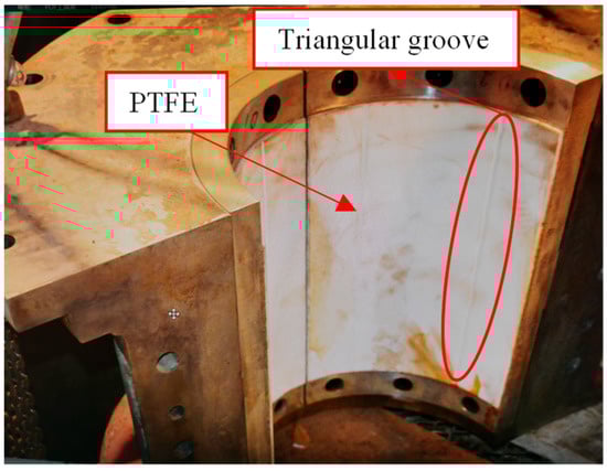
Figure 1.
Water-lubricated hydrodynamic journal bearing coated with PTFE.
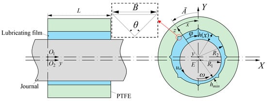
Figure 2.
Nomenclature of water-lubricated hydrodynamic journal bearings.

Table 1.
Parameters of water-lubricated hydrodynamic journal bearings.
3. Reynolds Lubrication Equation and Numerical Solution
3.1. Flow Model of Lubricating Film
As mentioned above, the Reynolds lubrication equation is adopted to verify the CFD results that were calculated by Fluent. From the current literature, there is no Reynolds lubrication equation combined with a three-dimensional slip velocity model that is available to verify the CFD method. Therefore, the non-slip boundary condition is used in the Reynolds lubrication equation. The flow regime in the water-lubricated hydrodynamic journal bearing needs to be determined. The modified Reynolds number is calculated by Equation (1) [45].
where ω is the angular velocity, R1 is the journal radius, c is the nominal clearance, and υ is the kinematic viscosity of lubricant. With the parameters in Table 1, the Reynolds number is 633.2, and the flow state is laminar.
The simplified Reynolds lubrication equation is obtained under isothermal, incompressible, and laminar flow conditions. Then, the flow model of hydrodynamic lubricating film is established as:
where x and y stand for the circumferential and axial coordinates, respectively, h is the film thickness [46], and ua is the circumferential velocity on the journal.
3.2. Numerical Solution
The finite difference method is selected to numerically solve Equation (2). The lubricating film is expanded into a rectangular computational domain, and the grid is uniformly divided. The dissection is performed at the maximum gap of the circular physical domain, which the periodical boundary condition is adopted to connect, and the physical quantities on each pair of periodic nodes are equal. Pressure Dirichlet boundary conditions are adopted for the grooves and ends of bearings [47]. The grid nodes are easy to number logically, which are structural grids, as shown in Figure 3.
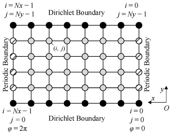
Figure 3.
Structural grids.
The analytical method is adopted to solve . The derivatives of Equation (2) with respect to x-direction are replaced by the following central difference schemes:
The derivatives concerning y-direction also adopt the central difference schemes. With the above difference schemes, the iteration scheme of Equation (2) is obtained as:
where the subscript P denotes the node at which the partial differential equation is approximated. The subscript l represents the node neighboring to P at which the pressure is not updated yet in the current iteration. The subscript m denotes the node neighboring to P at which the pressure has been updated in the current iteration. The superscript n represents the current iteration number. A is determined by geometric quantities, fluid properties, numerical schemes, etc. Q covers all the terms not containing unknown variables. λ represents the relaxation factor. The maximum dimensionless pressure difference between two successive iterations is determined as the convergence criteria. When this difference is less than a pre-selected residual ε, the iteration is stopped, as expressed by Equation (6):
with the converged pressure field, according to the coordinate system in Figure 2, the load capacity is calculated by the following equations:
with the above theoretical and numerical method, an in-house solver is developed and used to verify the CFD method. Once again, the in-house solver adopts the non-slip boundary condition.
4. CFD Method
4.1. Grid Generation
Firstly, the three-dimensional geometry of lubricating film is established. Then, the ICEM CFD module is used in ANSYS Workbench, and the geometric model is divided into hexahedral grids. Mesh refinement is performed at the minimum film thickness, as shown in Figure 4.
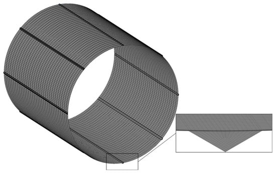
Figure 4.
Mesh for Fluent.
A case with an attitude angle of 22.5° and an eccentricity ratio of 0.6 is selected for grid sensitivity analysis. Figure 5 presents the load capacity versus the number of elements. The load capacity is changeless when the grid number reaches around 1,248,672. To balance the calculation accuracy and time efficiency, the number of elements is determined as 2,032,416.
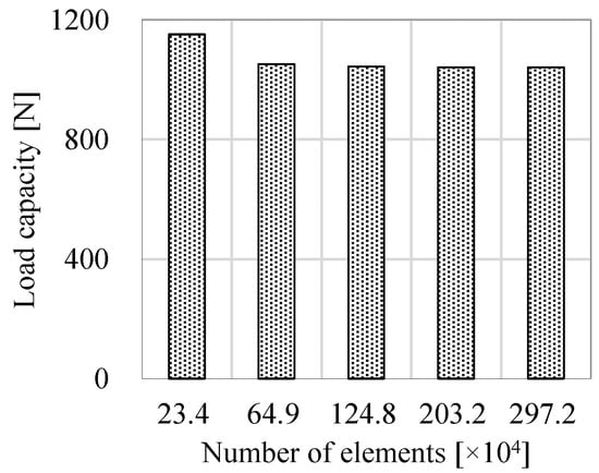
Figure 5.
Grid sensitivity analysis.
4.2. Simulation Setup
The three-dimensional incompressible Navier–Stokes equation and continuity equation are used to solve the flow field in the lubrication gap.
The continuity equation is given as:
The Navier–Stokes equation is given as:
where the subscripts i and j follow the tensor operation law.
The water-lubricated hydrodynamic journal bearing at different eccentricity ratios (e = E/c) is simulated by Fluent. The laminar model is adopted. The pressure outlet boundary conditions are set at the bearing ends. The discrete accuracy of each term is second order. The convergence residuals are 10−6.
5. Three-Dimensional Slip Velocity Model
Figure 6 shows one-dimensional slip velocity. Assuming that the flow is one-dimensional, laminar, and incompressible, a general form of the slip velocity is given as:
where us is the slip velocity and Ls is the slip length. is the derivative of the velocity component that is parallel to the shear direction, relative to displacement in the perpendicular direction.
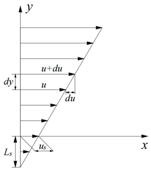
Figure 6.
One-dimensional slip velocity.
The three-dimensional slip velocity model is obtained by generalizing from Equation (12). Assuming that the flow is three-dimensional, laminar, incompressible, and isotropic, and inspired by the three-dimensional shear stress equation, the three-dimensional slip velocity equation is proposed as:
where is the i-direction slip velocity. The three-dimensional slip velocity model is written in C++ and embedded into Fluent via User Defined Function. It is used to calculate the slip velocity on the PTFE surface, namely the bushing inner surface.
6. Results and Discussion
6.1. Verification of CFD Method
Figure 7 compares the load capacity that is predicted by Fluent and the in-house solver under non-slip velocity boundary conditions. The two curves of load capacity versus eccentricity ratio are basically consistent with each other, and the result of Fluent is slightly larger than the in-house solver. Since the pressure Dirichlet boundary condition that is equal to the pressure at the bearing ends is used in grooves, the pressure in grooves is underestimated, leading to lower load capacity, but ensuring good convergence.
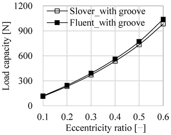
Figure 7.
Comparisons of the load capacity between Fluent and the in-house solver.
In order to further verify the accuracy of the results by Fluent, the bearing from [48] is simulated by Fluent, and the results agree well, as shown in Figure 8.
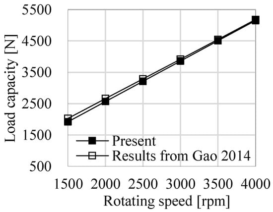
Figure 8.
Comparisons of the load capacity between Fluent and Gao 2014 [48].
The above comparisons verified that the numerical simulation of water-lubricated hydrodynamic journal bearings by Fluent is accurate and reliable.
6.2. Effects of Slip Velocity on Load Capacity
Figure 9 shows the effect of slip length on the load capacity under the attitude angle of 22.5°. The slip length is 0 µm under the non-slip condition. Under the same eccentricity ratio, the load capacity decreases with the increase in slip length. For example, under the eccentricity ratio of 0.3, the load capacity is 391 N under non-slip boundary condition, 379 N under slip length of 4 µm, 371 N under slip length of 8 µm, and 367 N under slip length of 12 µm. However, with the increase in eccentricity ratio, the decreased amplitude of the load capacity relative to the slip length gradually increases. Under the same slip length, the load capacity increases as the eccentricity ratio increases.
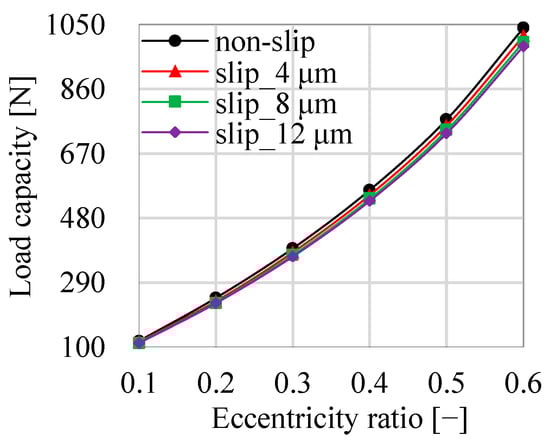
Figure 9.
Load capacity under different slip lengths.
To understand how the load capacity of water-lubricated journal bearings decreases with the increase of slip length, the eccentricity ratio of 0.6 is taken as an example, and the lubricating film pressure at different slip lengths is compared, as shown in Figure 10. Compared with cylindrical bearings without grooves, the film pressure of grooved bearing is not smoothly distributed, where the groove lowers pressure. The minimum thickness of lubricating film is located at the circumferential position of 180°. The maximum pressure of lubricating film occurs in the circumferential position of 90° to 180°. As the slip length increases, the maximum pressure decreases. The minimum pressure of lubricating film appears in the circumferential position of 180° to 270°. With the increased slip length, the minimum pressure rises. For instance, when the bearing has non-slip velocity, the maximum pressure is 1.126 bar, while the minimum pressure is 0.902 bar. When the slip length stands at 4 µm, 8 µm, and 12 µm, respectively, the maximum pressure is 1.120 bar, 1.116 bar, and 1.112 bar, while the minimum pressure is 0.904 bar, 0.906 bar, and 0.909 bar. That is to say, the pressure gradient in the circumferential direction decreases as the slip length increases, thus a smaller load capacity is generated.
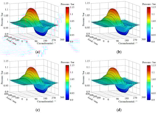
Figure 10.
Comparison of lubricating film pressure under different slip lengths; (a) non-slip; (b) Ls = 4 μm; (c) Ls = 8 μm; (d) Ls = 12 μm.
Figure 11 shows the effect of the attitude angle on the load capacity. As shown in Figure 11a, under the non-slip conditions, the effect of the attitude angle on the load capacity is insignificant. Taking the eccentricity ratio of 0.3, for example, when the attitude angle stands at 0°, 11.25°, 22.75°, and 33.75°, respectively, the load capacity is 392 N, 390 N, 391 N, and 390 N. As shown in Figure 11b, when the slip velocity boundary condition is considered, the slip length of 8 µm is taken as an example, the load capacity increases with the increase of attitude angle. The eccentricity ratio of 0.3 is taken as an example. When the attitude angle is at 0°, 11.25°, 22.75°, and 33.75°, respectively, the load capacity is 347 N, 357 N, 371 N, and 386 N.
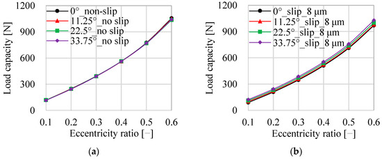
Figure 11.
Comparison of load capacity under different attitude angle; (a) non-slip boundary condition; (b) slip velocity.
6.3. Effects of Slip Velocity on Friction Power
Figure 12 shows the effect of the slip length on the friction power under the attitude angle of 22.5°. Under the same eccentricity ratio, the friction power decreases with the increase in the slip length. For example, under the eccentricity ratio of 0.3, the load capacity is 17.03 W under the non-slip boundary conditions. When the slip length is at 4 µm, 8 µm, and 12 µm, respectively, the friction power is 16.97 W, 16.92 W, and 16.90 W. However, with the increase of eccentricity ratio, the decreased amplitude of friction power relative to the slip length gradually increases. Under the same slip length, the friction power increases as eccentricity ratio increases.
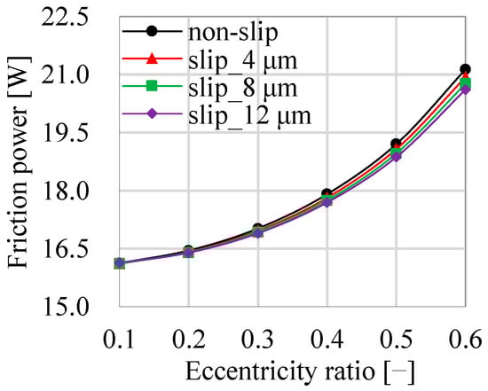
Figure 12.
Friction power under different slip lengths.
Figure 13 shows the effect of the attitude angle on the friction power. As shown in Figure 13a, when the slip velocity boundary condition is not considered, the effect of the attitude angle on the friction power is ignorable. Taking the eccentricity ratio of 0.3 for example, when the attitude angle stands at 0°, 11.25°, 22.75°, and 33.75°, respectively, the friction power is 17.03 W, 17.02 W, 17.03 W, and 17.01 W. As shown in Figure 13b, when the slip velocity boundary condition is considered, the slip length of 8 µm is taken as an example, the friction power increases with the increase of the attitude angle. The eccentricity ratio of 0.3 is taken as an example. When the attitude angle stands at 0°, 11.25°, 22.75°, and 33.75°, respectively, the friction power is 16.81 W, 16.87 W, 16.92 W, and 16.98 W.
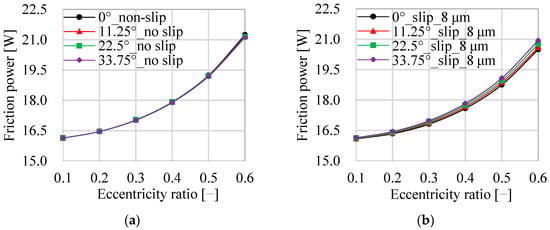
Figure 13.
Comparison of the friction power under different attitude angles; (a) non-slip boundary conditions; (b) slip velocity.
7. Conclusions
The commercial software Fluent is adopted to simulate the water-lubricated hydrodynamic journal bearing. The numerical results of Fluent are verified to be reliable by comparing with the Reynolds lubrication equation and the open literature. A three-dimensional slip velocity model is proposed and embedded in Fluent. The effects of slip length on the static characteristics of journal bearings, including the load capacity, lubricating film pressure, and friction power, are analyzed. The conclusions are as follow:
(1) Under the same eccentricity ratio, with the increase in the slip length, the load capacity decreases due to the decrease in the pressure circumferential gradient. Under the same slip length, the load capacity increases with the increase in eccentricity ratio. Under the same eccentricity ratio and the same slip length, the load capacity amplifies with the enlargement in the attitude angle. However, the effect of the attitude angle on the load capacity is insignificant under the boundary conditions of non-slip velocity.
(2) Under the same eccentricity ratio, the friction power decreases with the increase in the slip length. Under the same slip length, the friction power rises with the increase in the eccentricity ratio. Under the same eccentricity ratio and the same slip length, the friction power grows with the increase in the attitude angle. In addition, the effect of the attitude angle on the friction power is negligible under the non-slip boundary condition.
Author Contributions
Software, Y.G.; validation, Y.G. and J.C.; formal analysis, H.S. and A.L.; writing—original draft preparation Y.G. and J.C.; writing—review and editing, Y.G. and J.C.; supervision, L.C. All authors have read and agreed to the published version of the manuscript.
Funding
This research was funded by the Postdoctoral Research Fund of Jiangsu Province, China (Grant No. 2021K569C), National Natural Science Foundation of China (Grant No. 51779214), The Natural Science Foundation of the Jiangsu Higher Education Institutions of China (Grant No. 22KJB570005), and a project funded by the Priority Academic Program Development of Jiangsu Higher Education Institutions (PAPD).
Institutional Review Board Statement
Not applicable.
Informed Consent Statement
Not applicable.
Data Availability Statement
Data on the analysis and reporting results during the study can be obtained by contacting the authors.
Acknowledgments
The authors thank the College of Hydraulic Science and Engineering, Yangzhou University. The authors acknowledge the funding support from the Postdoctoral Research Fund of Jiangsu Province, National Natural Science Foundation of China, The Natural Science Foundation of the Jiangsu Higher Education Institutions of China, and the Priority Academic Program Development of Jiangsu Higher Education Institutions. A huge thanks is due to the editor and reviewers for their valuable comments to improve the quality of this paper.
Conflicts of Interest
The authors declare no conflict of interest.
Nomenclature
| Ā | attitude angle, ° |
| B | groove width, mm |
| c | nominal clearance, mm |
| E | eccentricity, mm |
| e | eccentricity ratio, e = E/c |
| FX | X-direction load capacity, N |
| FY | Y-direction load capacity, N |
| F | load capacity, N |
| fi | i-direction body force, N·m−3 |
| h | film thickness, mm |
| hmin | minimum film thickness |
| i | index for circumferential difference scheme |
| j | index for axial difference scheme |
| L | bearing length, mm |
| Ls | slip length, μm |
| ng | groove number |
| Nx | circumferential grid node number |
| Ny | axial grid node number |
| O1 | bearing center |
| O2 | journal center |
| p | pressure, pa |
| pi,j | internal node |
| R1 | journal radius, mm |
| R2 | bearing inside radius, mm |
| Rm | Reynolds number |
| ua | journal circumferential velocity, m·s−1 |
| us | slip velocity, m·s−1 |
| x | circumferential coordinate |
| y | axial coordinate |
| z | radial coordinate |
| Greek symbols | |
| ρ | density, kg·m−3 |
| μ | lubricant dynamic viscosity, Pa·s |
| υ | lubricant kinematic viscosity, m2·s−1 |
| ε | residual |
| φ | circumferential angle, ° |
| ω | angular velocity, rad·s−1 |
| λ | over-relaxation factor |
| θ | groove angle, ° |
| Superscripts | |
| n | iteration number |
| Subscripts | |
| i | free index |
| j | dummy index |
References
- Pai, R.; Hargreaves, D.J. Water lubricated bearings. Green Tribol. 2012, 49, 347–391. [Google Scholar] [CrossRef]
- Jin, J.; Zhang, G.X.; Wang, X.J. Experiment and simulations on lubrication performance of EMP journal bearing. J. Shanghai Univ. (Engl. Ed.) 2004, 8, 85–89. [Google Scholar] [CrossRef]
- Wu, Z.; Zeng, L.; Chen, K.; Chen, J.; Zhang, Y. Experiments on laminar flow between parallel plates with a heterogeneous slip/no-slip surface. Tribol. Trans. 2019, 2, 801–811. [Google Scholar] [CrossRef]
- Jendoubi, H.; Smerdova, O.; Brunetière, N. Unexpected frictional behavior of laser-textured hydrophobic surfaces. Lubricants 2021, 9, 31. [Google Scholar] [CrossRef]
- Naduvinamani, N.B.; Hiremath, P.S.; Gurubasavaraj, G. Squeeze film lubrication of a short porous journal bearing with couple stress fluids. Tribol. Int. 2001, 34, 739–747. [Google Scholar] [CrossRef]
- Gururajan, K.; Prakash, J. Effect of velocity slip in a narrow rough porous journal bearing. Proc. Inst. Mech. Eng. Part J J. Eng. Tribol. 2003, 217, 59–70. [Google Scholar] [CrossRef]
- Rao, R.R.; Prasad, K.R. Effects of velocity-slip and viscosity variation on journal bearings. ANZIAM J. 2004, 46, 143–155. [Google Scholar] [CrossRef][Green Version]
- Ma, G.J.; Wu, C.W.; Zhou, P. Wall slip and hydrodynamics of two-dimensional journal bearing. Tribol. Int. 2007, 40, 1056–1066. [Google Scholar] [CrossRef]
- Aurelian, F.; Patrick, M.; Mohamed, H. Wall slip effects in (elasto) hydrodynamic journal bearings. Tribol. Int. 2011, 44, 868–877. [Google Scholar] [CrossRef]
- Wang, L.L.; Lu, C.H.; Ma, J.K.; Ding, J.; Liang, P. Study on two-dimensional wall slip of sleeve bearing. J. Mech. Eng. 2012, 48, 105–112. [Google Scholar] [CrossRef]
- Phani, K.M.; Samanta, P.; Murmu, N.C. Rigid rotor stability analysis on finite hydrostatic double-layer porous oil journal bearing with velocity slip. Tribol. Trans. 2015, 58, 930–940. [Google Scholar] [CrossRef]
- Chen, D.J.; Zhou, S.; Bian, Y.H.; Fan, J.W.; Zhang, F.H. Analysis and experimental research of hydrostatic spindle oil film slip phenomenon. J. Mech. Eng. 2016, 52, 144–153. [Google Scholar] [CrossRef]
- Chen, D.J.; Gao, X.; Xue, B.; Fan, J.W. Static performance analysis of hydrostatic thrust bearing under the influence of velocity slip. Lubr. Eng. 2018, 43, 6. (In Chinese) [Google Scholar] [CrossRef]
- Cheng, F.; Ji, W. A velocity-slip model for analysis of the fluid film in the cavitation region of a journal bearing. Tribol. Int. 2016, 97, 163–172. [Google Scholar] [CrossRef]
- Lin, Q.; Wei, Z.Y.; Zhang, Y.B.; Wang, N. Effects of the slip surface on the tribological performances of high-speed hybrid journal bearings. Proc. Inst. Mech. Eng. Part J J. Eng. Tribol. 2016, 230, 1149–1156. [Google Scholar] [CrossRef]
- Kalavathi, G.K.; Dinesh, P.A.; Gururajan, K. Influence of roughness on porous finite journal bearing with heterogeneous slip/no-slip surface. Tribol. Int. 2016, 102, 174–181. [Google Scholar] [CrossRef]
- Xie, Z.; Rao, Z.; Liu, L.; Chen, R. Theoretical and experimental research on the friction coefficient of water lubricated bearing with consideration of wall slip effects. Mech. Ind. 2016, 17, 106. [Google Scholar] [CrossRef]
- Xie, Z.; Ta, N.; Rao, Z. The lubrication performance of water lubricated bearing with consideration of wall slip and inertial force. J. Hydrodyn. Ser. B 2017, 29, 52–60. [Google Scholar] [CrossRef]
- Li, Y.Q.; Yang, P.; Chen, W. Design of liquid metal lubricated spiral groove bearing considering influences of turbulence and slip. J. Xi’an Jiaotong Univ. 2019, 53, 15–23. [Google Scholar] [CrossRef]
- Cui, S.; Zhang, C.; Fillon, M.; Gu, L. Optimization performance of plain journal bearings with partial wall slip. Tribol. Int. 2020, 145, 106137. [Google Scholar] [CrossRef]
- Li, F.; Li, X.; Shang, D. Dynamic modeling and vibration characteristics analysis of deep-groove ball bearing, considering sliding effect. Mathematics 2021, 9, 2408. [Google Scholar] [CrossRef]
- Feng, W.; Han, Y.; Xiang, G.; Wang, J. Hydrodynamic lubrication analysis of water-lubricated bearings with partial microgroove considering wall slip. Surf. Topogr. Metrol. Prop. 2021, 9, 015019. [Google Scholar] [CrossRef]
- Gu, Y.; Cheng, J.; Xie, C.; Li, L.; Zheng, C. Theoretical and numerical investigations on static characteristics of aerostatic porous journal bearings. Machines 2022, 10, 171. [Google Scholar] [CrossRef]
- Iftimie, D.; Sueur, F. Viscous boundary layers for the Navier–Stokes equations with the Navier slip conditions. Arch. Ration. Mech. Anal. 2011, 199, 145–175. [Google Scholar] [CrossRef]
- Simmons, J.E.L.; Knox, R.T.; Moss, W.O. The development of PTFE (polytetrafluoroethylene)-faced hydrodynamic thrust bearings for hydrogenerator application in the United Kingdom. Proc. Inst. Mech. Eng. Part J J. Eng. Tribol. 1998, 212, 345–352. [Google Scholar] [CrossRef]
- Young, R.J. Deformation mechanisms in polytetrafluoroethylene. Polymer 1975, 16, 450–458. [Google Scholar] [CrossRef]
- Choo, J.H.; Glovnea, R.P.; Forrest, A.K.; Spikes, H.A. A low friction bearing based on liquid slip at the wall. ASME J. Tribol. 2007, 129, 611–620. [Google Scholar] [CrossRef]
- Kalin, M.; Velkavrh, I.; Vižintin, J. The Stribeck curve and lubrication design for non-fully wetted surfaces. Wear 2009, 267, 1232–1240. [Google Scholar] [CrossRef]
- Kodnyanko, V.; Shatokhin, S.; Kurzakov, A.; Pikalov, Y.; Strok, L.; Pikalov, I.; Grigorieva, O.; Brungardt, M. Theoretical efficiency study of output lubricant flow rate regulating principle on the example of a two-row aerostatic journal bearing with longitudinal microgrooves and a system of external combined throttling. Mathematics 2021, 9, 1698. [Google Scholar] [CrossRef]
- Lu, Z.; Liu, L.; Wang, X.; Ma, Y.; Chen, H. Dynamic modeling and bifurcation analysis of blade-disk rotor system supported by rolling bearing. Appl. Math. Model. 2022, 106, 524–548. [Google Scholar] [CrossRef]
- Gu, Y.; Pei, J.; Yuan, S.; Zhang, J. A pressure model for open rotor–stator cavities: An application to an adjustable-speed centrifugal pump with experimental validation. J. Fluids Eng. 2020, 142, 101301. [Google Scholar] [CrossRef]
- Peng, Y.C.; Chen, X.Y.; Zhang, K.W.; Hou, G.X. Numerical research on water guide bearing of hydro-generator unit using finite volume method. J. Hydrodyn. Ser. B 2007, 19, 635–642. [Google Scholar] [CrossRef]
- Yang, H.; Li, X.; Xu, J.; Guo, Y.; Li, B. Modeling and fatigue characteristic analysis of the gear flexspline of a harmonic reducer. Mathematics 2022, 10, 868. [Google Scholar] [CrossRef]
- Gu, Y.; Cheng, J.; Wang, P.; Cheng, L.; Si, Q.; Wang, C.; Shouqi, Y. A flow model for side chambers of centrifugal pumps considering radial wall shear stress. Proc. Inst. Mech. Eng. Part C J. Mech. Eng. Sci. 2022, 09544062211073023. [Google Scholar] [CrossRef]
- Zhang, F.; Zhu, L.; Chen, K.; Yan, W.; Appiah, D.; Hu, B. Numerical simulation of gas–liquid two-phase flow characteristics of centrifugal pump based on the CFD–PBM. Mathematics 2020, 8, 769. [Google Scholar] [CrossRef]
- Lin, Y.; Li, X.; Li, B.; Jia, X.; Zhu, Z. Influence of impeller sinusoidal tubercle trailing-edge on pressure pulsation in a centrifugal pump at nominal flow rate. J. Fluids Eng. 2021, 143, 091205. [Google Scholar] [CrossRef]
- Zhang, D.; Wang, H.; Liu, J.; Wang, C.; Ge, J.; Zhu, Y.; Chen, X.; Hu, B. Flow characteristics of oblique submerged impinging jet at various impinging heights. J. Mar. Sci. Eng. 2022, 10, 399. [Google Scholar] [CrossRef]
- Gu, Y.; Li, J.; Wang, P.; Cheng, L.; Qiu, Y.; Wang, C.; Si, Q. An improved one-dimensional flow model for side chambers of centrifugal pumps considering the blade slip factor. J. Fluids Eng. 2022, 144, 091207. [Google Scholar] [CrossRef]
- Gu, Y.; Pei, J.; Yuan, S.; Wang, W.; Zhang, F.; Wang, P.; Desmond, A.; Liu, Y. Clocking effect of vaned diffuser on hydraulic performance of high-power pump by using the numerical flow loss visualization method. Energy 2019, 170, 986–997. [Google Scholar] [CrossRef]
- Kan, K.; Chen, H.; Zheng, Y.; Zhou, D.; Binama, M.; Dai, J. Transient characteristics during power-off process in a shaft extension tubular pump by using a suitable numerical model. Renew. Energy 2021, 164, 109–121. [Google Scholar] [CrossRef]
- Hu, B.; Wang, H.; Liu, J.; Zhu, Y.; Wang, C.; Ge, J.; Zhang, Y. A numerical study of a submerged water jet impinging on a stationary wall. J. Mar. Sci. Eng. 2022, 10, 228. [Google Scholar] [CrossRef]
- Brajdic-Mitidieri, P.; Gosman, A.D.; Ioannides, E.; Spikes, H.A. CFD analysis of a low friction pocketed pad bearing. ASME J. Tribol. 2005, 127, 803–812. [Google Scholar] [CrossRef]
- Guo, Z.; Hirano, T.; Kirk, R.G. Application of CFD analysis for rotating machinery—Part I: Hydrodynamic, hydrostatic bearings and squeeze film damper. J. Eng. Gas Turbines Power 2005, 127, 445–451. [Google Scholar] [CrossRef]
- Crous, J.M.; Heyns, P.S.; Dirker, J. On the influence of coupled and uncoupled fluid dynamic models in a large scale journal bearing. Appl. Math. Model. 2016, 40, 1218–1231. [Google Scholar] [CrossRef]
- Hamrock, B.J.; Schmid, S.R.; Jacobson, B.O. Fundamentals of Fluid Film Lubrication; CRC Press: Boca Raton, FL, USA, 2004. [Google Scholar]
- Böhle, M. Numerical investigation of the flow in hydrostatic journal bearings with porous material. ASME 2018, 51579, V003T12A025. [Google Scholar] [CrossRef]
- Tao, W. Numerical Heat Transfer, 2nd ed.; Xi’an Jiaotong University Press: Xi’an, China, 2001. (In Chinese) [Google Scholar]
- Gao, G.; Yin, Z.; Jiang, D.; Zhang, X. Numerical analysis of plain journal bearing under hydrodynamic lubrication by water. Tribol. Int. 2014, 75, 31–38. [Google Scholar] [CrossRef]
Publisher’s Note: MDPI stays neutral with regard to jurisdictional claims in published maps and institutional affiliations. |
© 2022 by the authors. Licensee MDPI, Basel, Switzerland. This article is an open access article distributed under the terms and conditions of the Creative Commons Attribution (CC BY) license (https://creativecommons.org/licenses/by/4.0/).