Article

Effect of Cross-Joints Fin on the Thrust Performance of Bionic Pectoral Fins

1
School of Marine Science and Technology, Northwestern Polytechnical University, Xi’an 710072, China
2
Unmanned Vehicle Innovation Center, Ningbo Institute of NPU, Ningbo 315103, China
3
Key Laboratory of Unmanned Underwater Vehicle Technology of Ministry of Industry and Information Technology, Northwestern Polytechnical University, Xi’an 710072, China
4
Department of Mechanical, Materials and Manufacturing Engineering, University of Nottingham, Nottingham NG7 2GX, UK
*
Author to whom correspondence should be addressed.
J. Mar. Sci. Eng. 2022, 10(7), 869; https://doi.org/10.3390/jmse10070869
Submission received: 18 May 2022 / Revised: 22 June 2022 / Accepted: 23 June 2022 / Published: 24 June 2022
(This article belongs to the Special Issue Frontiers in Deep-Sea Equipment and Technology)

Abstract

:
Cownose rays have a high forward propulsive performance due to their unique oscillating fin structure (named the cross-bracing structure), which differs from undulatory fish. The cross-bracing structure obtained through anatomy, on the other hand, is extremely complex. Hence, researchers used simple structures to model the biological structure to target the individual factors that affect cownose ray cruising performance. This paper simplified the cross-bracing fin structure to a cross-joints fin (CJF) structure with 18 designs. CJFs had five different joint widths (2 mm, 3 mm, 4 mm, 5 mm, and 6 mm) in both spanwise and chordwise directions, and these had two fin thicknesses (1.5 mm, 2.5 mm). The joint widths of CJF are related to the stiffness of the spanwise and chordwise fins (Fin stiffness increases with joint width). The experiments were conducted in a still water tank (1.5 m × 0.8 m × 0.8 m) with three stroke amplitudes (30°, 50°, 70°) and three flapping frequencies (0.4 Hz, 0.6 Hz, 0.8 Hz) for each fin, making up 162 distinct sets of data. The experimental results showed the following: (1) at low wingtip Reynolds numbers, the high stiffness of the CJF causes a significant reduction in thrust. In particular, high stiffness results in a low thrust averaged from all motion parameters; (2) at high wing tip Reynolds numbers, the effect of changing spanwise stiffness on thrust is more significant than the effect of changing chordwise stiffness. This paper compares the effects of spanwise and chordwise stiffness on thrust performance, indicating that the magnitude of spanwise stiffness should be considered when designing the bionic oscillating pectoral fin structure.

1. Introduction

The demand for offshore development has increased research into underwater vehicles’ capacity for long-distance sailing and high maneuverability in recent years. People studied marine fish that evolved over hundreds of millions of years to master robust locomotion in search of inspiration for new underwater vehicle designs. Manta rays are cartilaginous fish that, thanks to their unique pectoral fin structure, can migrate through the ocean and swim flexibly in complex aquatic environments such as coral reefs [1]. Stingrays, Cownose rays, and other cartilaginous fishes with batoid pectoral fins such as manta rays have similar movements named MPF (median/paired fin propulsion). Although having similar movements, they are distinguished by the number of waves λ that pass along the body chord during swimming, as undulatory locomotion mode (λ > 1) and oscillating locomotion mode (λ < 0.5) [1]. The MPF movement aroused the interest of many researchers who considered that the flexible pectoral fin structure was responsible for greater swimming efficiency and maneuverability [2,3,4]. The ability of pectoral fins to generate thrust is linked to the kinematics of batoid pectoral fins, which can be used to guide the design of new underwater vehicles.
Several studies on the kinematics and anatomy of batoid pectoral fin fishes have been published [1,3,5,6,7,8,9]. Calcification patterns were discovered by photographing the fins of batoid wings with high-resolution radiography. The radiographic calcification map shows that the fins are made up of segments of small fin bones joined together. The unique structure of the oscillating fins, relative to the undulatory swimmer fins, is the cross-bracing structure in the center of the wing, which increases the chordwise stiffness of the pectoral fin [6]. Furthermore, researchers found morphological differences in cartilage arrangement, which are primarily differences in skeletal units and radial orientation, by using computerized tomography to reconstruct the distribution of the pectoral fin skeleton in Dasyatis sabina (Atlantic ray) and Rhinoptera bonasus (Cownoes Ray). In addition, they measured the magnitude of stresses at different locations of the pectoral fins by tensile loading to predict the effect of pectoral fin deformation [3]. The study of the pectoral fin motion of Taeniura lymma discovered that the fish’s swimming body chordwise wave speed is increased by high fin frequency, but the number of chord waves decreases [1]. This phenomenon implies that the chordwise stiffness of the fins may increase with the increasing speed (i.e., increasing thrust). These studies suggest that pectoral fins with varying spanwise and chordwise stiffness produce specific biological propulsion effects.
Researchers built a series of bionic batoid pectoral fins to study the relationship between stiffness, motion parameters, and thrust. They proposed that thrust increases with batoid fins’ beat frequency, but propulsion efficiency decreases with frequency increasing [4,10,11,12,13,14,15,16,17,18,19,20,21]. Some researchers found that stiffness distribution has more significant effects on thrust by studying simplified fish mold of BCF (body and caudal fin mode) [22,23,24,25,26]. This change in stiffness along the body significantly improved propulsion performance, which inspired researchers to design batoid pectoral fins with different spanwise and chordwise stiffness changes [10,18,22,27,28]. In recent years, researchers summarized the variable stiffness bionic fish [29]. These experiments showed that simplified pectoral fin structures could explain the effect of spanwise or chordwise stiffness on thrust. Still, these designs only focused on the effect of a single spanwise or chordwise stiffness. Most of these were conducted in a single paper to analyze the effect of spreading or chordal stiffness on propulsion performance. There was no comparison of the effect of chordal stiffness and spreading on propulsion performance for the same size fins and motion parameters. Therefore, developing a new bionic pectoral fin structures is significant to compare the effects of spanwise and chordwise stiffness on the thrust.
This paper purposes to compare the effects of the spanwise stiffness and chordwise stiffness of the oscillating pectoral fins on thrust performance simultaneously. A simplified bionic pectoral fin named cross-joints fin (CJF) was first fabricated. This novel fin structure had five types of cross-joint widths that varied in the spanwise and chordwise directions. Next, the relationship between the width and stiffness of CJF was tested. By varying the width of the cross-joints, CFJ could vary both spanwise and chordwise stiffness on the same shape fin. Finally, the author measured CJFs’ thrust and lift forces with varying spanwise and chordwise stiffnesses in a still water tank to study the effect of pectoral fin stiffness on propulsion performance.
This paper is structured as follows. Section 2 explains the CJF structure design of the cownose ray’s skeletal structure. Section 3 discusses the effect of spanwise and chordwise stiffness on thrust performance in one oscillating pectoral fin. Section 4 summarizes the main research work of the article and discusses future research prospects.

2. Methodology

2.1. Cross-Joints Fin Design

The CJF mimics the shape of a cownose ray and the oscillating fish’s cartilaginous skeletal element arrangement. Figure 1a depicts a cownose ray specimen with a similar triangular pectoral fin that was CT scanned for skeletal structure. The radiograph of the pectoral fin obtained from the oscillating fish is shown in Figure 1b [6], where the blue circles indicate the fin joints along the spanwise direction and the green circles indicate the fin joints along the chordwise direction. This structure where the spanwise and chordwise joints are next to each other is named as cross-bracing structure in biology, which enhances the chordwise stiffness of the oscillating fins.
The researchers reconstructed the cownose ray skeletal model shown in Figure 1c, using blue lines to represent the distribution of leading edge fins in spanwise and green lines to represent the distribution of skeletal structures in chordwise root direction. The interconnected elemental points represent the distribution of the oscillating pectoral fin skeleton [3]. The forward sweep angle θ, about 30°, is the angle between the leading edge wing and the spanwise direction. The colors in Figure 1c represent the displacement of the element points of the oscillating wing under the classical motion parameter, where the green color represents the small displacement, and the red color represents the large displacement. We can observe three-color partitions clearly, where are a green part (root wing), a yellow part (middle wing), and a red part (tip wing) along the spanwise direction. These color areas are approximately equidistantly distributed and change weakly along the chordwise direction.
The CJF was designed In a simplified triangular shape in Figure 1d, consisting of the fins ray and the fin surface. The fins ray of CJF made from polylactic acid (PLA) filament (with Young’s Modulus of 1.514 Gpa) had one spanwise fin ray and three chordwise fins rays containing two spanwise joints and one chordal joint, respectively. The CJF exhibited a similar spanwise and chordwise deformation as Figure 1c. The fins’ spanwise width (sw) was uniform as sw = 6 mm, and the chordwise width (cw) was uniform as cw = 6 mm. The spanwise joint width (sjw) and chordwise joint width (cjw) of CJF had the same width variation (Δw), ranging from 2 mm to 6 mm at 1 mm intervals. So CJF had five types of spanwise stiffness that the cjw did not change (cjw = 6 mm) while the sjw changed (sjw = 2 mm–6 mm, Δw = 1 mm). Similarly, it had five types of chordwise stiffness that the sjw did not change (sjw = 6 mm) while the cjw changed (cjw = 2 mm–6 mm, Δw = 1 mm). Fin thickness (tfin) of CJF were 1.5 mm and 2.5 mm. The fin surface was made from laser-cut silicone rubber film with a thickness of 0.8 mm. The silicone rubber film was bonded to the fins ray by smooth-on’s sil-poxy, which was also soft after curing and had similar properties to silicone. This silicone rubber film had stretch and deformability and does not disturb the deformation of the CJF excessively. The forward sweep of CJF is similar to the forward sweep of the biological pectoral fin, which is 30 degrees. The span length of CJF is 0.12 m and the root chord length is 0.14 mm, and its area is 0.0084 m2.
As a result, there are 18 types of CJFs. Those CJFs are simplified to the fish’s skeletal structure, shown in Figure 1e, allowing for discussing and analyzing the effect of the spanwise or chordwise joints on the pectoral fins, respectively. So, this design highlights the structure of the cross-joints, to compare the effects of spanwise and chordwise stiffness.
The tip-to-tip deflection of a fin during the beat cycle can be used to evaluate its deformation capacity, so the bending stiffness is used to quote the spreading flexibility [17]. Bending stiffness is defined as the force applied to the tip of the fin divided by the deformation distance of the fin. The rotational support surface of CJF is fixed to a vertically oriented support bracket, as shown in Figure 2, to prevent the fin from rotating due to external forces. Figure 2 shows the stiffness test points in the spanwise and chordwise directions. As you can see in this figure, there are two red points: one on the wingtip and the other on the trailing edge of the root fin. As a result, the stiffness in the spanwise and chordwise directions is easily classified. The dashed CJF in the Figure represents the pectoral fins’ original position, and the solid pectoral fins represent the deformation effect after being subjected to the gravitational force of a weight (denoted by W). Hspan and Hchord denote the displacement of the spanwise and chordwise tips, respectively.
The deformation of the CJF by the weight (W = 50 g) is shown in Figure 3, where the x-axis represents the chordwise joint width (cjw) and the spanwise joint width (sjw) at tfin = 1.5 mm and tfin = 2.5 mm, respectively. The y-axis represents the magnitude of the bending stiffness, while the green and blue squares represent the chordwise and spanwise stiffness, respectively. The bending stiffness increases with the joint width of the CJF, especially the thickness of the CJF increases significantly for the bending stiffness.

2.2. Motion Parameters

According to the authors’ previous study [30], the oscillating fins are driven by fin root, following a regular sinusoidal show in the formula:
A t = A b + A 0 sin 2 π f t
where, A 0 is the angle amplitude of oscillating fin, A b is the bias angle amplitude, and t is the time.
During swimming, the oscillating fish has several kinematic parameters. Thus the experiments require the design of multiple kinematic parameters to investigate the effect of joint width on different kinematic thrusts. There are nine sets of kinematic parameters for each CJF, with the stroke frequency range (f) set to 0.4 Hz, 0.6 Hz, and 0.8 Hz, and the angular amplitude (A0) set to 30°, 50°, and 70°. Asymmetric flapping is not considered in this paper (Ab = 0°). The nine kinematic parameter sets result in 9 wingtip Reynolds numbers (ReWing) ranging from 1.3 × 10⁴ to 5.1 × 10⁴.
R e W i n g = V · L c h o r d ν
where, Lchord is the root chord length, ν is the kinematic viscosity of water, and the V is the fin spanwise tip average velocity shown in the Formula (3):
V = 4 · L s p a n · s i n A 0 π 180 · f
where, L s p a n is the CFJ’s spanwise length.

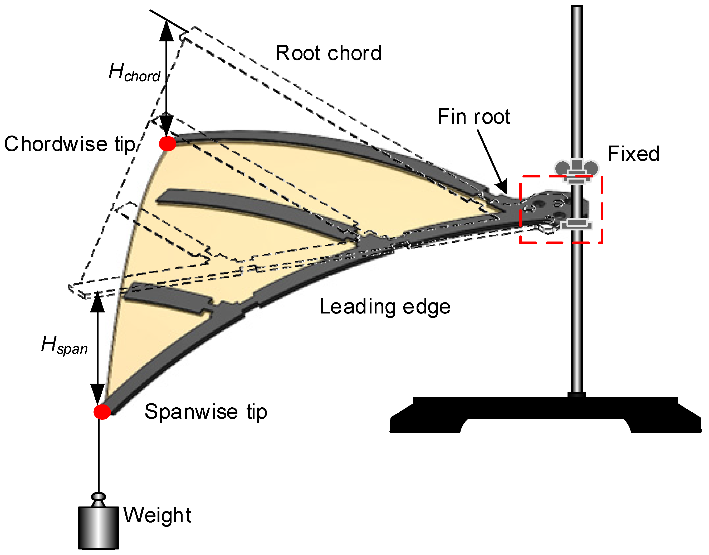
2.3. Experiment Setup

Figure 4a,b shows the experimental environment, while Figure 4c shows the fins installed on the model awaiting testing. The experiment was carried out under a still water tank (1.5 m × 0.8 m × 0.8 m) shown in Figure 4a. During the experiment, the tank’s water level was 0.7 m high. The experimental model was fixed with an aluminum rod placed in the water at a depth of 0.5 m. The experimental model was 0.5 m and 0.4 m away from the frontwall and sidewall of the tank, respectively, thereby eliminating the influence of wall effects.
The experiment model consisted of a cownose ray-like shape body structure, a drive servo, a CJF, and an ATI force sensor, as shown in Figure 4c. The CJF was driven by a servo motor, GWD-500 (IP68), which could generate a maximum torque of 3 Nm at 7.4 V, and reached a total speed of 330°s−1. In this experiment, the thrust (T) was measured by An ATI Nano 17 IP68 si-50-0.5 [31]. The sensing range of Fx and Fy is 50 N, Fz is 70 N, and the resolution of Fx, Fy, and Fz is 1/80 N. The torque in all directions is 500 Nm with the resolution of 1/16 Nmm.
The experiment system consisted of a computer for reading and saving data, a power supply box for powering the control board and the servo motor, a control board for driving the servo motor, an ATI sensor and acquisition card, and an experiment model, as shown in Figure 4d. Every ten cycles of fins oscillation were tested three times for each kinematic parameter to get average trust T and mean square error with the acquisition frequency of 100 Hz.

3. Results and Discussion

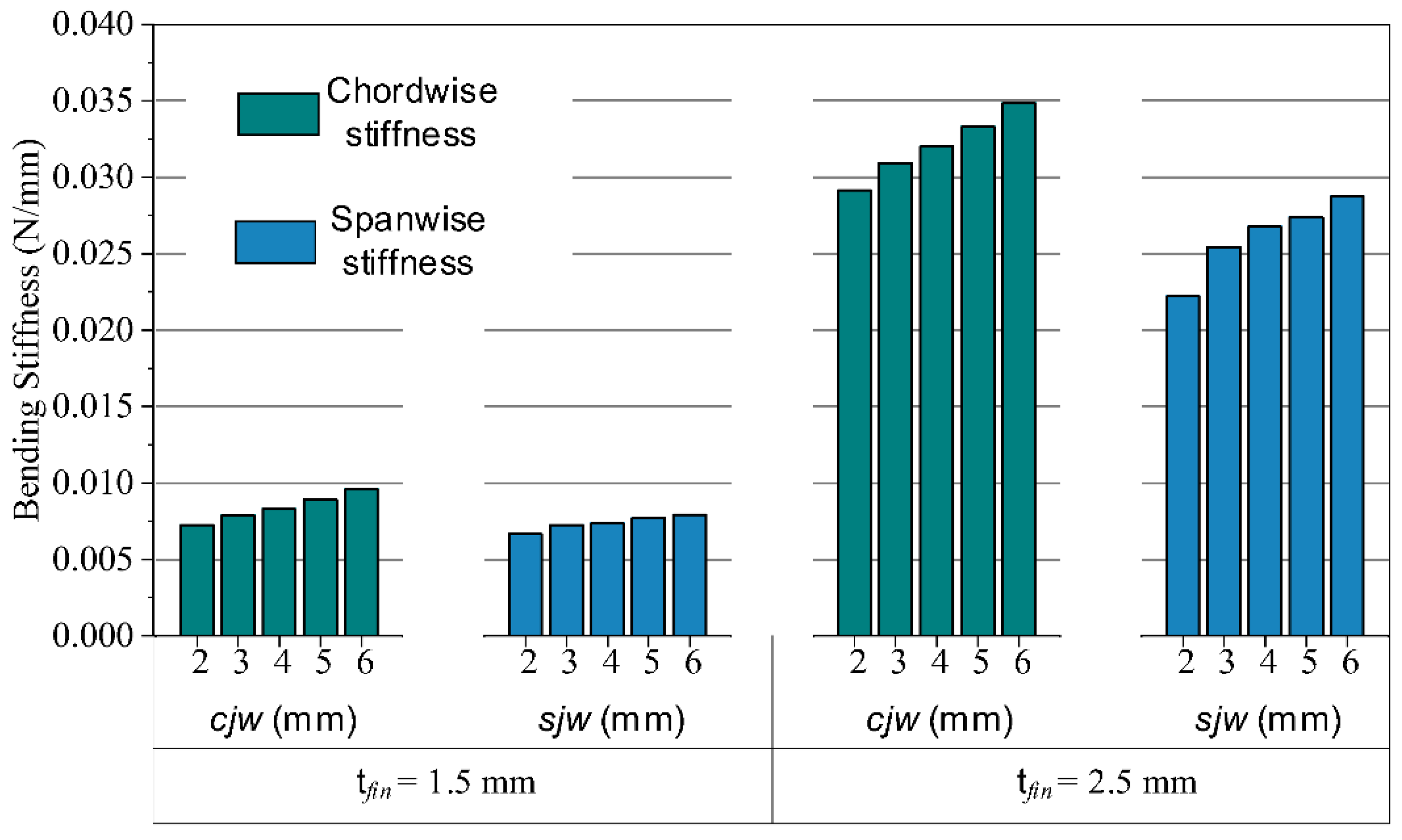
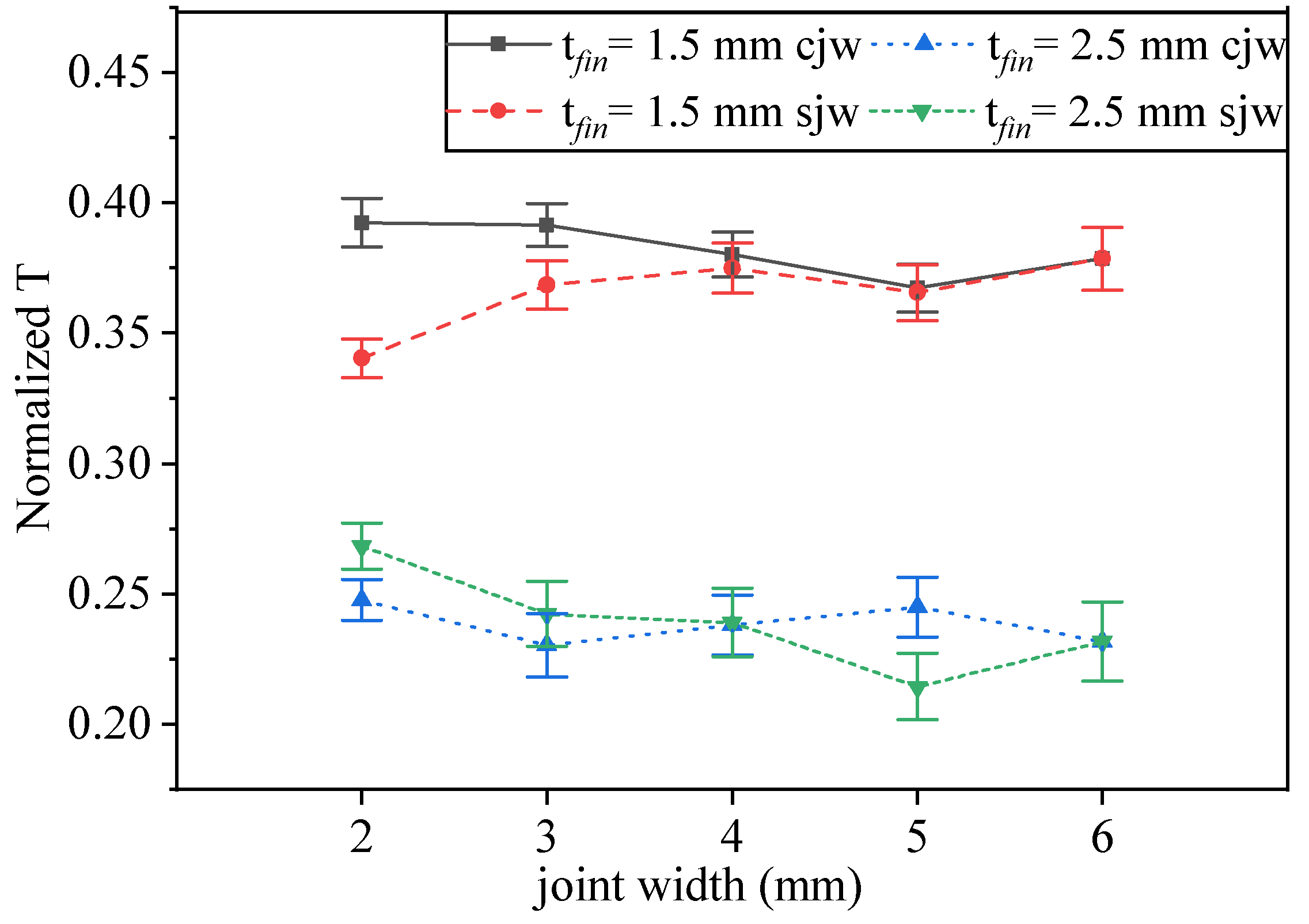
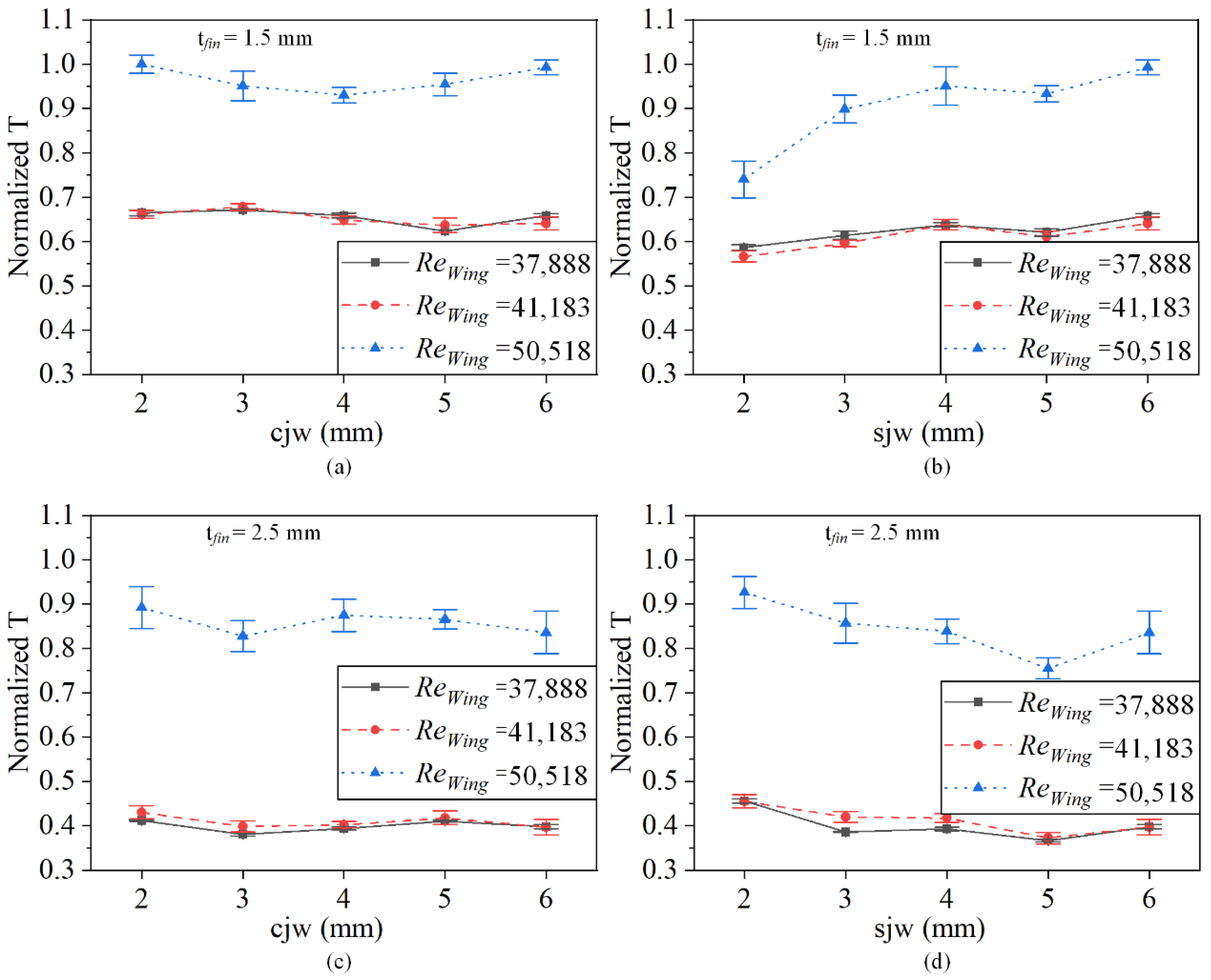
3.1. Thrust Performance with Spanwise and Chordwise Stiffness

All thrusts in this paper were dimensionless and denoted by Normalized T (Dividing each operating condition T by the maximum T) to compare thrust variations due to spanwise and chordwise stiffnesses. The reason for normalization is to illustrate the trend of variation. For the comparison of normalized T, I chose the maximum thrust as the criterion in the 162 data sets. The curves of the instantaneous example thrust can be seen in the Supplementary Materials.
The structure parameters of CJF, as shown in Table 1, change the stiffness of the chordwise or spanwise fin while sjw or cjw is unchanging. Each thickness fin has the same variation in joint width to compare the effect of overall stiffness. As a result, this structure can be used to separately discuss the effect of CJF spanwise and chordwise stiffness changes on propulsion performance. The movement parameters, as shown in Table 2, are used in every type of CJF.
As shown in Figure 5, the Normalized T of the spanwise stiffness and chordwise stiffness are compared for different motion parameters in this image. The purpose of drawing an isoplot of the normalized T is to qualitatively describe the effect on the different CJFs by two variables (amplitude and frequency). Each graph represents one type of stiffness distribution. Each graph’s horizontal and vertical coordinate represents the frequency and amplitude, respectively. Through the experimental conditions in this paper, as shown in Table 1 and Table 2. Thus each graph contains nine data points, but the relationship between the thrust force and the two variables can be plotted through the difference. The Normalized T with red and blue colors represents large thrusts and small thrusts. The width of the joints gradually increases (Same as bending stiffness increases) from left to right at the same horizontal position. The higher two rows show CJFs with a thickness of 1.5 mm, while the lower two rows show CJFs with a thickness of 2.5 mm.
The Normalized T isoplot shows that the 2.5 mm thick CJF has a bluer area at low motion parameters than the 1.5 mm thick CJF. This phenomenon is due to the bionic pectoral fins’ increased overall stiffness, which results in less susceptibility to bending deformation at low motion parameters. The red part (higher thrust) in the second and fourth rows has a more significant area change than in the first and third rows. The spanwise stiffness of this CJF structure produces a significant change in thrust in response to changes in motion parameters.
As shown in Figure 6, the average normalized T of each design of CJF is the arithmetically average of the normalized T for nine motion parameters. When the tfin = 1.5 mm, the average normalized T increases max 11.22% with the increased sjw. When the tfin = 2.5 mm, the average normalized T decreases max 25.08% with the increased sjw. In comparison, the average normalized T changes max 6.37% and 4.74% with the increased cjw. The spanwise joints have a more significant effect on the overall average thrust than the chordwise joints, as shown in Figure 6. Pectoral fins with higher overall stiffness reduce the overall thrust level.
The variation of the normalized T magnitude with the ReWing is shown in Figure 7. When the CJF thickness tfin = 1.5 mm, the growth trend of thrust is almost smooth. When the CJF thickness tfin = 2.5 mm, the growth trend of thrust is slow firstly and then grows steeply when the ReWing is over 40,000. When the ReWing number is over 35,000, the effect of thrust has significant differences in the spanwise direction, as shown in Figure 7b,d.

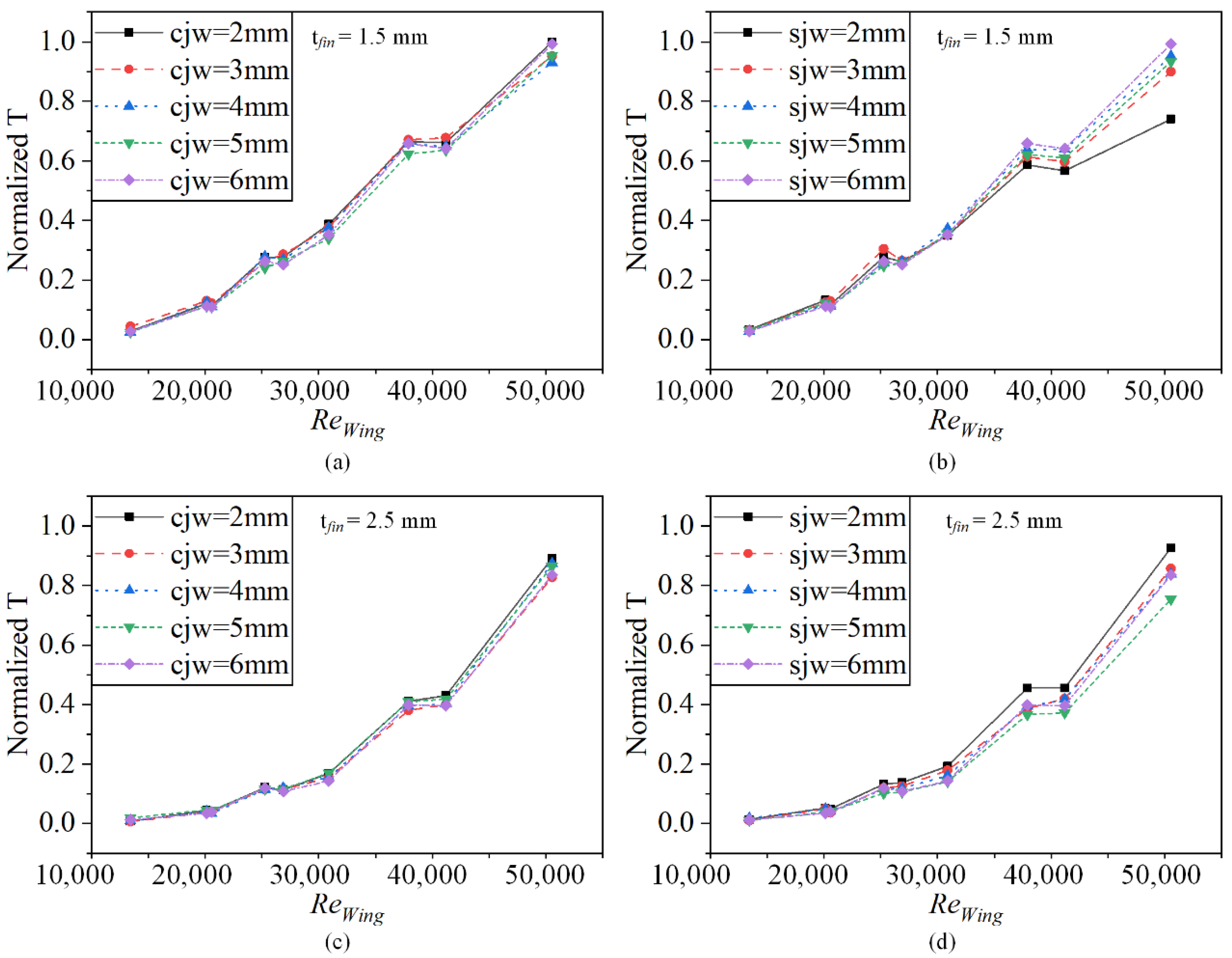
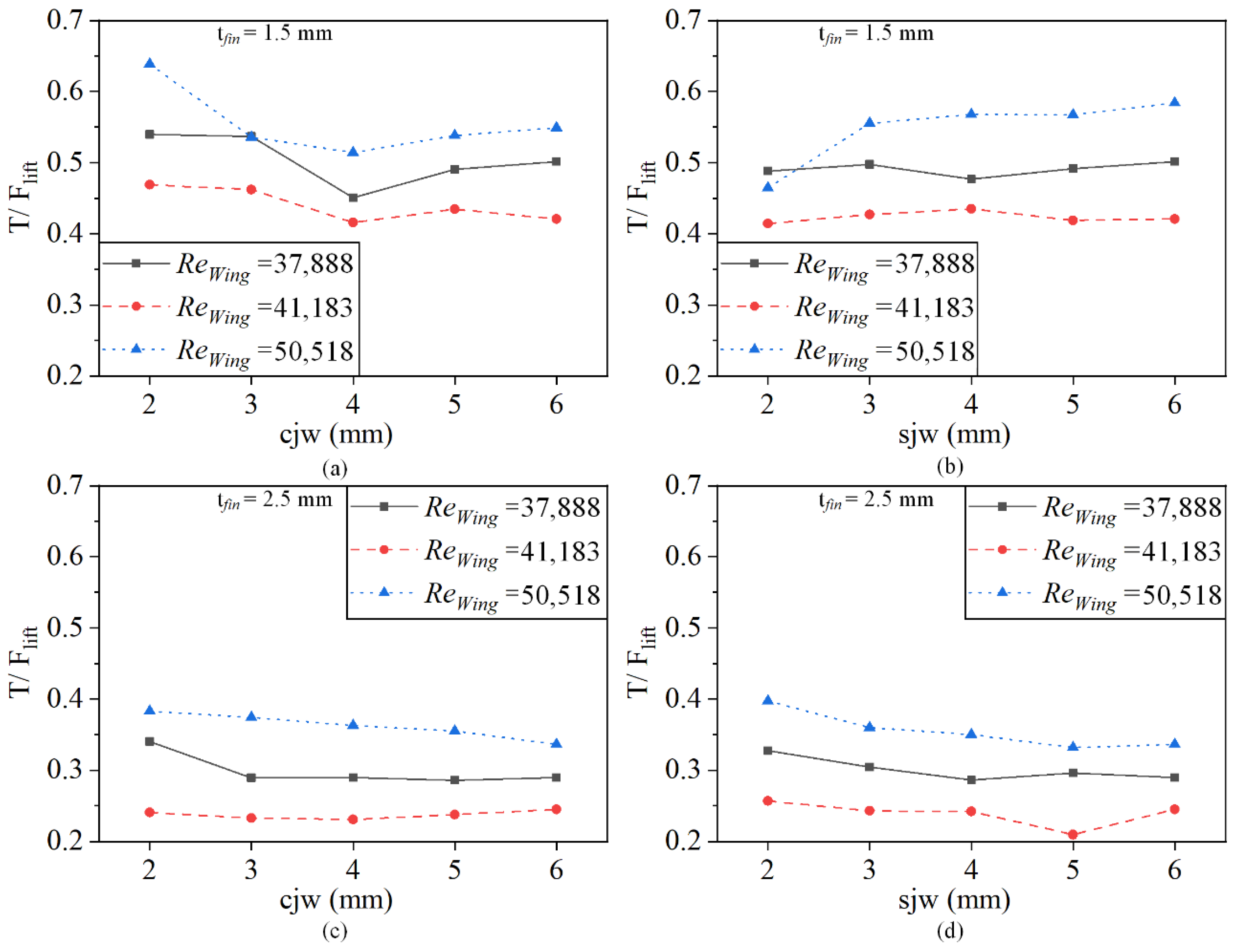
3.2. Stiffness Variation at High Wing Tip Reynolds Number

The variation of normalized T with chordwise joint width is not significant, as shown in Figure 8a,c. The variation of the normalized T decreases and then increases with the cjw as shown in Figure 8a, at ReWing = 50,518. This phenomenon is similar to the results of Chew [10]. Such results illustrate the limited role of chordwise stiffness on the thrust of CJF. It requires softer fins to produce chordwise deformation and enough fins stiff to have a reaction force against the water.
As shown in Figure 8b,d, the increasing sjw increase thrust at CJF thickness tfin = 1.5 mm and decrease thrust at CJF thickness tfin = 2.5 mm. When ReWing = 50,518, the maximum thrust variation is 35.6% and 22.7% at tfin =1.5 mm and tfin =2.5 mm, respectively.
The pectoral fins in this paper generate forces in three directions Fx, Fy, Fz. Fx, Fy, and Fz represent thrust, side force, and lift, respectively. Similar to the study of aircraft wings, the main focus is on average thrust (T) and average lift (Flift). The thrusts-lift ratio (T/Flift) was calculated by dividing the thrust value by the lift force (Flift). The greater the ratio of T/Flift during force generation in the pectoral fins, the more effective this structure is at generating thrust. At tfin = 1.5 mm, as shown in Figure 9a, the T/Flif tends a decrease and then increase trend as the chordwise joints width increases. This phenomenon indicates that the rise of chordwise stiffness will somewhat lead to the weakening of the chordwise wave effect, which will result in the decrease of the thrust ratio in the total force. However, a specific increase in chordwise stiffness is beneficial for thrust improvement. This phenomenon makes it difficult to explicitly choose the chordwise stiffness to boost the thrust.
As shown in Figure 9b,d, the increase or decrease in T/Flif is different. This phenomenon coincides with the trend of the normalized T. This illustrates that we can improve thrust by varying the amount of stiffness in the span direction. When the overall fin stiffness is low, choosing stiff fins enhances the ability of the pectoral fins to resist the water reaction force and increases the percentage of thrust in the total force. Similarly, when the overall fin stiffness is high, choosing softer fins enhances the propulsion ability of the pectoral fins to reduce the percentage of lift force in the total force.

4. Conclusions

The experimental results show that fin stiffness distribution has different phenomena under different overall stiffness(tfin). The average normalized T of tfin = 1.5 mm and tfin = 2.5 mm, changes max 11.22% and 25.08% with the increased sjw, respectively. In general, a pectoral fin with higher overall stiffness reduces the overall thrust level. At lower wingtip Reynolds numbers, the stiffer pectoral fin’s weak deformability generates less thrust, resulting in less effective thrust generated by the pectoral fin in the chordwise direction. Therefore, in fin design, attention should first be paid to the classical motion speed of the experimental bio-robot to select the fin thickness with the appropriate overall stiffness size.
Further, at a higher wing tip Reynolds number, the change in spreading stiffness has a greater effect on the change in thrust. Changing the chordwise stiffness on the thrust of the designed oscillating pectoral fin is not as pronounced as that of changing the spreads stiffness, when ReWing = 50,518, the maximum thrust variation is 35.6% and 22.7% at tfin = 1.5 mm and tfin = 2.5 mm, respectively. Therefore, during the fin design process, more attention should be paid to the selection of fins with the appropriate spreading stiffness distribution.
Compared with the current work of stiffness on thrust performance, most recent work analyzes and studies the optimal stiffness distribution in a single direction. The swing of the pectoral fins is a complex structure that couples wave propagation in two directions. In this paper, the pectoral fins with cross joints can be designed to simultaneously analyze the effects of the spanwise and chordwise stiffness changes on the propulsion performance, and a more obvious conclusion is obtained that the spanwise stiffness has a more significant effect. This conclusion is similar to the conclusion related to fish tail [32]. It provides the basis for my future research on the influence of spanwise and chordwise synthesis on propulsion performance. The findings of this paper can aid in the design of the oscillating pectoral fin structure to some extent. On the one hand, variable stiffness fins can be designed to improve the overall thrust effect of pectoral fin propulsion, while on the other hand, the value of the spanwise stiffness should be given more consideration in the design of the oscillating pectoral fin structure.

Supplementary Materials

The following supporting information can be downloaded at: https://www.mdpi.com/article/10.3390/jmse10070869/s1, Figure S1: The example thrust from ATI sensor (tfin = 1.5 mm, A0 = 70°, f = 0.8 Hz, cjw = 6 mm).

Author Contributions

Supervision, Y.C. (Yong Cao), Y.C. (Yonghui Cao), G.P., Q.H. and X.D.; Writing—original draft, Y.L.; writing—review and editing, Y.L. and Y.C. (Yong Cao). All authors have read and agreed to the published version of the manuscript.

Funding

This research was funded by the National Natural Science Foundation of China: 51879220; National Natural Science Foundation of China: 52001260; National Key Research and Development Program: 2020YFB1313200.

Institutional Review Board Statement

Not applicable.

Informed Consent Statement

Not applicable.

Data Availability Statement

Not applicable.

Conflicts of Interest

The authors declare no conflict of interest.

References

  1. Rosenberger, L.J. Pectoral fin locomotion in batoid fishes: Undulation versus oscillation. J. Exp. Biol. 2001, 204, 379–394. [Google Scholar] [CrossRef]
  2. Maia, A.M.; Wilga, C.A.; Lauder, G.V. Biomechanics of locomotion in sharks, rays, and chimaeras. Biol. Sharks Relat. 2012, 1, 125–151. [Google Scholar]
  3. Russo, R.S.; Blemker, S.S.; Fish, F.E.; Bart-Smith, H. Biomechanical model of batoid (skates and rays) pectoral fins predicts the influence of skeletal structure on fin kinematics: Implications for bio-inspired design. Bioinspiration Biomim. 2015, 10, 046002. [Google Scholar] [CrossRef] [PubMed] [Green Version]
  4. Clark, R.P.; Smits, A.J. Thrust production and wake structure of a batoid-inspired oscillating fin. J. Fluid Mech. 2006, 562, 415–429. [Google Scholar] [CrossRef] [PubMed] [Green Version]
  5. Frank, F.; Christian, S.; Keith, M.; Liu, G.; Dong, H.; Hilary, B.S. Hydrodynamic Performance of Aquatic Flapping: Efficiency of Underwater Flight in the Manta. Aerospace 2016, 3, 20. [Google Scholar]
  6. Schaefer, J.T.; Summers, A.P. Batoid wing skeletal structure: Novel morphologies, mechanical implications, and phylogenetic patterns. J. Morphol. 2005, 264, 298–313. [Google Scholar] [CrossRef] [PubMed]
  7. Lindsey, C.C. Form, Function, and Locomotory Habits in Fish. Fish Physiol. 1978, 7, 1–100. [Google Scholar]
  8. Rosenberger, L.J.; Westneat, M.W. Functional morphology of undulatory pectoral fin locomotion in the stingray Taeniura lymma (Chondrichthyes: Dasyatidae). J. Exp. Biol. 1999, 202, 3523–3539. [Google Scholar] [CrossRef] [PubMed]
  9. Lauder, G.V. Function of the caudal fin during locomotion in fishes: Kinematics, flow visualization, and evolutionary patterns. Am. Zool. 2000, 40, 101–122. [Google Scholar] [CrossRef] [Green Version]
  10. Arastehfar, S.; Chew, C.M. Effects of root chord movement on thrust generation of oscillatory pectoral fins. Bioinspir. Biomim. 2020, 16, 036009. [Google Scholar] [CrossRef]
  11. Bianchi, G.; Cinquemani, S.; Resta, F. Bio-Inspired Design of an Underwater Robot Exploiting Fin Undulation Propulsion. Appl. Sci. 2021, 11, 2556. [Google Scholar] [CrossRef]
  12. Chen, J. Flexible tensegrity wing design and insights in principles of swimming kinematics of batoid rays. Bioinspir. Biomim. 2021, 16, 056007. [Google Scholar] [CrossRef] [PubMed]
  13. Xing, C.; Cao, Y.; Cao, Y.; Pan, G.; Huang, Q. Asymmetrical Oscillating Morphology Hydrodynamic Performance of a Novel Bionic Pectoral Fin. J. Mar. Sci. Eng. 2022, 10, 289. [Google Scholar] [CrossRef]
  14. Cai, Y.; Bi, S.; Li, G.; Hildre, H.P.; Zhang, H. From Natural Complexity to Biomimetic Simplification: The Realization of Bionic Fish Inspired by the Cownose Ray. IEEE Robot. Autom. Mag. 2018, 26, 27–38. [Google Scholar] [CrossRef]
  15. Arastehfar, S.; Chew, C.-M.; Jalalian, A.; Gunawan, G.; Yeo, K.S. A Relationship Between Sweep Angle of Flapping Pectoral Fins and Thrust Generation. J. Mech. Robot. 2018, 11, 011014. [Google Scholar] [CrossRef]
  16. Chew, C.-M.; Arastehfar, S.; Gunawan, G.; Yeo, K.S. Study of sweep angle effect on thrust generation of oscillatory pectoral fins. In Proceedings of the 2017 IEEE/RSJ International Conference on Intelligent Robots and Systems (IROS), Vancouver, BC, Canada, 24–28 September 2017; pp. 6271–6276. [Google Scholar]
  17. Arastehfar, S.; Gunawan, G.; Yeo, K.S.; Chew, C.-M. Effects of pectoral fins’ spanwise flexibility on forward thrust generation. In Proceedings of the 2017 IEEE International Conference on Robotics and Biomimetics (ROBIO), Macau, China, 5–8 December 2017; pp. 110–115. [Google Scholar]
  18. Chew, C.-M.; Lim, Q.-Y.; Yeo, K. Development of propulsion mechanism for Robot Manta Ray. In Proceedings of the 2015 IEEE International Conference on Robotics and Biomimetics (ROBIO), Zhuhai, China, 6–9 December 2015; pp. 1918–1923. [Google Scholar]
  19. Zhou, C.; Low, K.H. Better Endurance and Load Capacity: An Improved Design of Manta Ray Robot (RoMan-II). J. Bionic Eng. 2010, 7, S137–S144. [Google Scholar] [CrossRef]
  20. Yang, S.; Qiu, J.; Han, X. Kinematics modeling and experiments of pectoral oscillation propulsion robotic fish. J. Bionic Eng. 2009, 6, 174–179. [Google Scholar]
  21. Suzumori, K.; Endo, S.; Kanda, T.; Kato, N.; Suzuki, H. A bending pneumatic rubber actuator realizing soft-bodied manta swimming robot. In Proceedings of the 2007 IEEE International Conference on Robotics and Automation, Roma, Italy, 10–14 April 2007; pp. 4975–4980. [Google Scholar]
  22. Zhang, L.; Bi, S.; Cai, Y.; Niu, C.; Ma, H. Effect analysis of chordwise flexibility on propulsion performance of oscillating pectoral foils. In Proceedings of the 2012 IEEE International Conference on Robotics and Biomimetics (ROBIO), Guangzhou, China, 11–14 December 2012; pp. 765–770. [Google Scholar]
  23. Lucas, K.N.; Thornycroft, P.J.; Gemmell, B.J.; Colin, S.P.; Costello, J.H.; Lauder, G.V. Effects of non-uniform stiffness on the swimming performance of a passively-flexing, fish-like foil model. Bioinspir. Biomim. 2015, 10, 056019. [Google Scholar] [CrossRef] [Green Version]
  24. Reddy, N.S.; Sen, S.; Har, C. Effect of flexural stiffness distribution of a fin on propulsion performance. Mech. Mach. Theory 2018, 129, 218–231. [Google Scholar] [CrossRef]
  25. Kancharala, A.K.; Philen, M.K. Study of flexible fin and compliant joint stiffness on propulsive performance: Theory and experiments. Bioinspir. Biomim. 2014, 9, 036011. [Google Scholar] [CrossRef]
  26. Luo, Y.; Xiao, Q.; Shi, G.; Pan, G.; Chen, D. The effect of variable stiffness of tuna-like fish body and fin on swimming performance. Bioinspir. Biomim. 2020, 16, 016003. [Google Scholar] [CrossRef] [PubMed]
  27. Bi, S.; Cai, Y. Effect of spanwise flexibility on propulsion performance of a flapping hydrofoil at low Reynolds number. Chin. J. Mech. Eng. 2012, 25, 12–19. [Google Scholar] [CrossRef]
  28. He, J.; Cao, Y.; Huang, Q.; Pan, G.; Dong, X.; Cao, Y. Effects of Bionic Pectoral Fin Rays’ Spanwise Flexibility on Forwarding Propulsion Performance. J. Mar. Sci. Eng. 2022, 10, 783. [Google Scholar] [CrossRef]
  29. Zhu, H.; Sha, Y.; Ding, H. Research On Fish Variable Stiffness: A Review. In Proceedings of the 2021 IEEE International Conference on Unmanned Systems (ICUS), Beijing, China, 15–17 October 2021; pp. 224–231. [Google Scholar]
  30. Cao, Y.; Lu, Y.; Cai, Y.; Bi, S.; Pan, G. CPG-fuzzy-based control of a cownose-ray-like fish robot. Ind. Robot. Int. J. Robot. Res. Appl. 2019, 46, 779–791. [Google Scholar] [CrossRef]
  31. Automation, A.I. F/T Sensor: Nano17 IP65/IP68. Available online: https://www.ati-ia.com/products/ft/ft_models.aspx?id=Nano17+IP65%2fIP68 (accessed on 1 May 2022).
  32. Zhu, R.; Wang, J.; Dong, H.; Bart-Smith, H. Effects of Chordwise or Spanwise Non-uniform Stiffness on Propulsive Performance of Square Foil. In Proceedings of the AIAA Scitech 2021 Forum, Virtual, 11–15 January 2021. [Google Scholar]
Figure 1. Design of CJF. (a) Cownose ray sample; (b) cross-bracing structure in the pectoral fins; (c) pectoral fins model generated by 3D reconstruction after C.T. scan; (d) a basic design of CJF; (e) illustration of CJF on the cownose ray model.
Jmse 10 00869 g001
Figure 2. CJF spreadwise and chordwise bending stiffness test.
Jmse 10 00869 g002
Figure 3. The chordwise and spanwise bending stiffness of the CJF.
Jmse 10 00869 g003
Figure 4. Experimental setup and test system (a) The model of the experimental water tank; (b) experimental water tank; (c) experimental model; (d) experimental data processing system.
Jmse 10 00869 g004
Figure 5. Isobars of normalized T for different widths of CJFs with different motion parameters.
Jmse 10 00869 g005
Figure 6. Variation of each kinematic parameter’s average normalized T with joint width.
Jmse 10 00869 g006
Figure 7. Variation of normalized T with ReWing at various joint widths. (a) tfin = 1.5 mm, variation of Normalized T with ReWing at cjw; (b) tfin = 1.5 mm, variation of normalized T with ReWing at sjw; (c) tfin = 2.5 mm, variation of normalized T with ReWing at cjw; (d) tfin = 2.5 mm, variation of normalized T with ReWing at sjw.
Jmse 10 00869 g007
Figure 8. Variation of normalized T with various joint widths at ReWing > 35,000. (a) tfin = 1.5 mm, variation of normalized T with cjw; (b) tfin = 1.5 mm, variation of normalized T with sjw; (c) tfin = 2.5 mm, variation of normalized T with cjw; (d) tfin = 2.5 mm, variation of normalized T with sjw.
Jmse 10 00869 g008
Figure 9. Variation of T/Flift with various joint widths at ReWing > 35000. (a) tfin = 1.5 mm, variation of T/Flift with cjw; (b) tfin = 1.5 mm, variation of T/Flift with sjw; (c) tfin = 2.5 mm, variation of T/Flift with cjw; (d) tfin = 2.5 mm, variation of T/Flift with sjw.
Jmse 10 00869 g009
Table 1. The structure parameters of CJF.
Fin ThicknessJoints with
tfin = 1.5 mmsjw = 6 mmcjw = 2 mmcjw = 3 mmcjw = 4 mmcjw = 5 mmcjw = 6 mm
cjw = 6 mmsjw = 2 mmsjw = 3 mmsjw = 4 mmsjw = 5 mmsjw = 6 mm
tfin = 2.5 mmsjw = 6 mmcjw = 2 mmcjw = 3 mmcjw = 4 mmcjw = 5 mmcjw = 6 mm
cjw = 6 mmsjw = 2 mmsjw = 3 mmsjw = 4 mmsjw = 5 mmsjw = 6 mm
Table 2. The movement parameters of CJF.
ParametersValue
A0 (amplitude)30°50°70°
f (frequency)0.4 Hz0.4 Hz0.8 Hz
Publisher’s Note: MDPI stays neutral with regard to jurisdictional claims in published maps and institutional affiliations.

