1. Introduction
The difficulty in constructing fins and studying their parameters is mostly due to the numerous aspects that influence their features [
1,
2]. First and foremost, the interaction between fins and fluid is nonlinear, and the analysis of this should be regarded as continuous in both space and time [
3]. Even with fluid–structure interaction software [
4,
5,
6], this is challenging to analyse. Direct measurements of variables that provide information about the fluid–structure interaction problem are difficult to analyse [
7,
8,
9] due to the nonlinear relationship between the fin stiffness and the type of water flow (laminar, turbulent, or mixed). Therefore, most simulation evaluations assume that models are separate in space and that the fins are stiff pieces of equipment that connect to the human model with springs and dampers [
10,
11].
The thrust generated by divers can be measured using linked sensors; however, even the smallest link causes unwanted drag force [
12]. Furthermore, the associated sensors do not provide data on vertical movement.
Some studies in the field of swimming fins look at how much force is generated and how much oxygen is used [
13,
14]. However, when diving, oxygen intake is determined by metabolic processes, physical state, and training level. Furthermore, the characteristics of the fins are determined by the swimmers’ propensity and aptitude.
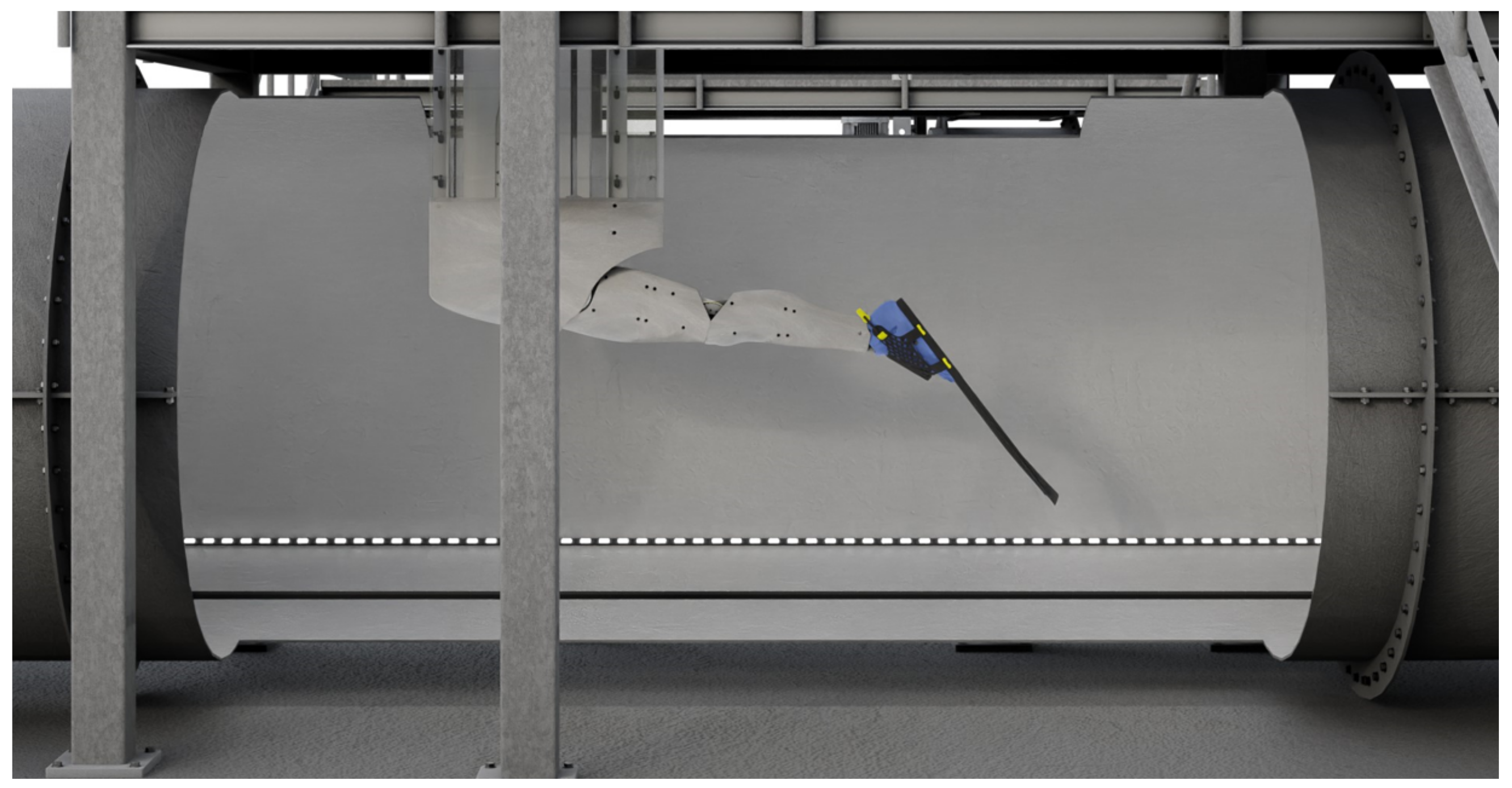
Therefore, in the first part of the investigation, a water tunnel test was used (
Figure 1). The methodology for assessing the dynamics and efficiency of diving fins is given in the report [
15]. This method is based on measuring the thrust of a manipulator that moves with the desired motion pattern [
16]. As a result, it is free of human mistakes and produces more reliable and independent data. Further, it is worth noting that only one artificial leg was created to decrease the influence of body shape on fin characteristics. As a result, a more in-depth study of the fin shape and the effect of material characteristics on a fin’s abilities should be conducted [
17,
18]. Furthermore, the fin characteristics can be examined as a function of water velocity [
19,
20,
21].
One disadvantage of water tunnel measurements is that they do not give information on the interaction between two fins and the diver’s body.
Taking into consideration all the arguments presented above, image processing was carried out to evaluate the newly designed folding biomimetic fins. Because only single fins were tested in the water tunnel to avoid turbulent flow contact between both fins, the swimming style with two legs acting together was adopted.
Tests in the swimming pool using image processing were the third stage of research, after the test in the water tunnel was conducted and the questionnaire was administered among a wide group of professional swimmers.
The newly designed biomimetic fins are described in the following sections using the mathematical relationships that were used for the analysis. The image processing system, technology and software are described in detail. Then, the results for two selected divers of both genders are presented in a table and discussed. At the end of the paper, the conclusions are presented.
2. The Biomimetic Folding Fins
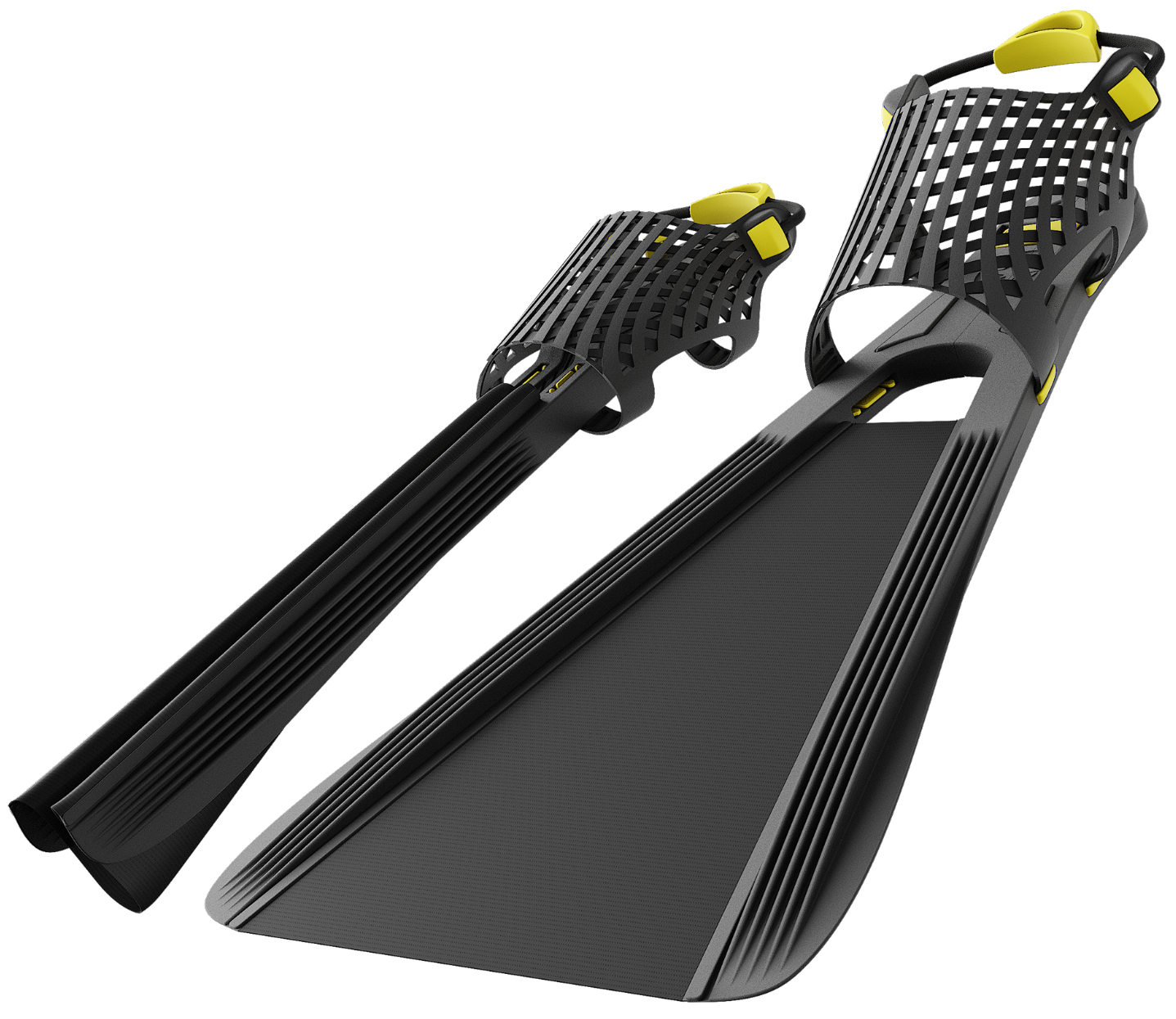
The biomimetic design and folding system of the newly developed fins are their most important aspects. As a result, they take up less area, which is significant not only from a military standpoint, but also from a tourism standpoint. Soldiers from special forces, as well as tourists, can reduce the space required for carrying fins by unfurling them immediately before swimming. The term biomimetic refers to the design of a thin membrane between two flexible ribs. The membrane design was inspired by the tail of a fish. The flexibility of the ribs can be selected depending on the skill and the experience of the diver. It was assumed that the newly designed biomimetic fins were useful for a diverse range of swimmers with varying abilities. The elasticity of the ribs is determined by the material used, as well as the shape and dimensions of the ribs.
Figure 2 depicts the design, while
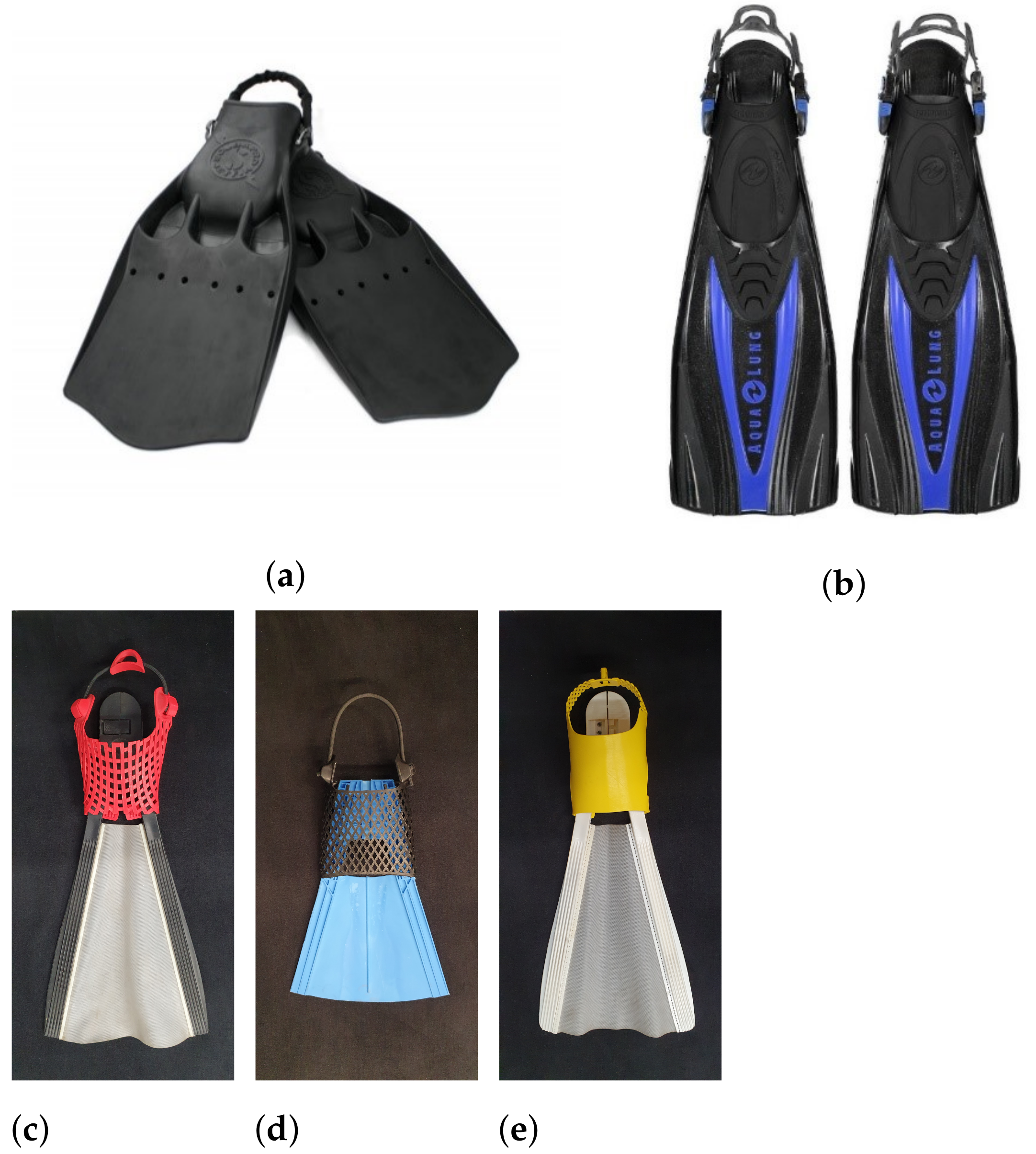
Figure 3 includes the three prototypes (type
—
Figure 3c; type
B—
Figure 3d; type
W—
Figure 3e) and two commercial fins (Jet Fin from Scubapro—
Figure 3a; Express from Aqualung—
Figure 3b). Two types of fins (
and
W) are intended for tourist purposes, and the
B type is used for rescue tasks.
In order to increase the elasticity of the designed fins, side ribs were designed with a variable profile. This reduces the load-bearing cross-section, which, consequently, for the same thermoplastic polymer, increases its elasticity. It was assumed that the geometrical dimensions of the unfolded recreational fins (W and type) should not exceed 600 × 300 × 100 mm; when folded, these dimensions should not exceed 600 × 100 × 100 mm. In the case of rescue fins (type B), the maximum size was set at 350 × 200 × 100 mm, and after folding, 350 × 100 × 80 mm.
The membrane is the main supporting element for all fins and introduces the main element of innovation due to its flexibility and deformation it undergoes when moving in the water.
A detailed description of the construction can be found in the Patent Application Publication US 2016/0023053.
The thermoplastic elastomers from the Thermoplastic Copolyester group were used for the tests. The material parameters used for production as well as the fatigue strength [
22] and the durability of the fins are presented in [
23].
The following chapter includes a mathematical study of all tested fins.
3. Mathematical Relations
Assuming a constant fluid density
and viscosity
, the interaction between the diver’s fin and water can be described by Equation (
1). This is derived from the Buckingham theory [
24]. This is commonly used due to the possibility of expressing nonlinear phenomena in a very compact form, using a reduced number of dimensionless variables.
All the five parameters are described below:
The stiffness coefficient changes in a way that it is not linear with the square of the water speed u. This affects the flexibility of the fin and the amplitude of the trailing edge.
is the Reynolds number (
3), which depends on the characteristic dimension
c (a characteristic length) and water viscosity
(here, both are assumed to be constant).
The Reynolds number can be described as the ratio of the inertial forces acting on the swimmer’s body to the corresponding viscous forces [
25]. Hence, this number is not directly dependent on the locomotion characteristics, but the shape of the body and its surface characteristics determine the tendency of the swimmer’s body to generate fluid resistance. These tests were conducted so that the drag force caused by surface wave motion was reduced in line with the relationship that was found in [
26].
is the Strouhal number defined in Equation (
4). The Strouhal number represents the ratio of unsteady to steady (inertial) forces [
12]. This is the most important relationship in the analysis and includes the amplitude of the trailing edge
A, frequency of fin motion
f, and the body swimmer velocity
u. The efficient propulsion is more likely to occur at around
[
1,
27,
28].
The image processing method was used to estimate the speed, frequency and amplitude of the trailing edge of the fins. Then, the Strouhal number was calculated and the results are depicted for five tested types of fins.
The following section describes the processing of a computer image in detail.
4. Image Processing Method
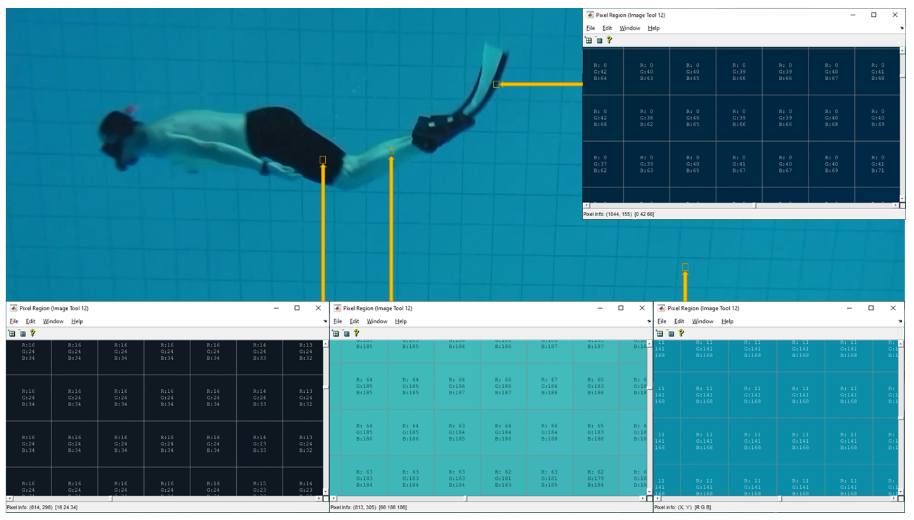
A waterproof Panasonic camera was used that can record 30 frames per second (fps) at a resolution of 1080 × 1920 × 3, where 1080 is the number of rows and 1920 is the number of columns in the matrix. The third dimension is represented by the colours: red, green, and blue. Because of the camera’s 8-bit format, each pixel described in the matrix cell has an RGB colour range of 0 to 255.
Figure 4 shows an example of one frame with the investigation region zoomed in.
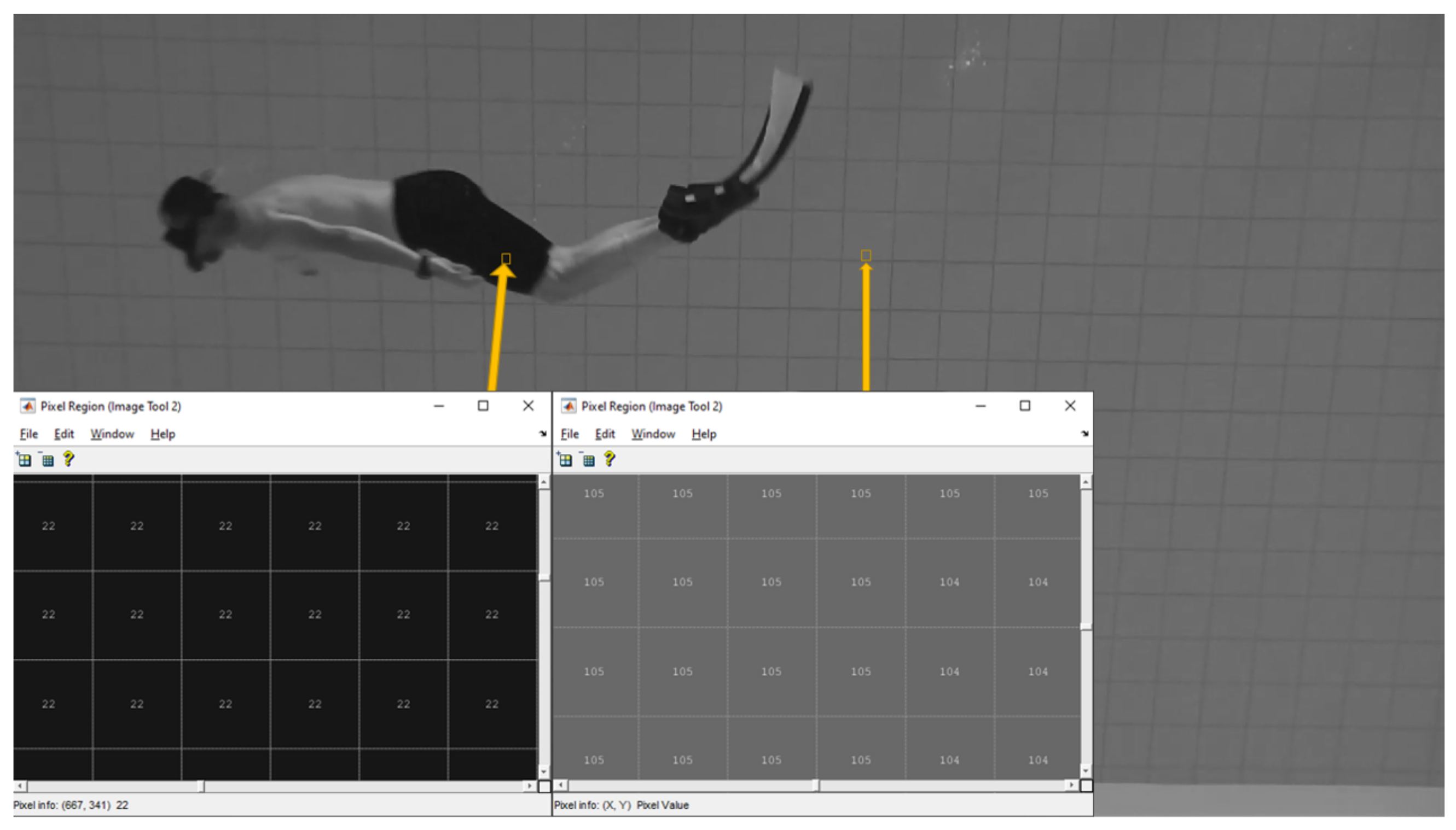
Based on the values in each cell of the matrix, the fins and other parts of interest, such as the head or swimming trunks, can be recovered from the background. The swimmer velocity can be determined by taking the swimming trunks or head displacement into account in the following frames. The option is determined by the colour of the trunks and hair, as well as the colour of the background. Each frame was downsized from 1080 × 1920 × 3 to 1080 × 1920 to save on memory size and the required computing power. The result of decomposing the three-dimensional matrix into three two-dimensional ones is shown in
Figure 5. The choice of which value, R, G, or B, is used for the subsequent calculation is determined by the diver uniform, fin colour, backdrop factors, and lighting conditions. Considering the data shown in
Figure 5, the B matrix appears to be most relevant for further investigation. This signifies that the contrast between the black areas and the background is the most varied.
Decomposition can be accomplished directly by selecting only one of three matrices or by converting a true-colour RGB image to a greyscale image by producing a weighted total of the R, G, and B components: R = 0.2989 + G = 0.5870 + B = 0.1140 [
29]. The formula removes the hue and saturation information while keeping the brightness information. The effect of converting a true-colour image RGB to greyscale is shown in
Figure 6. As a result of the conversion, the matrix has the same number of rows and columns, as well as a range of 0–255 for each cell. In the uint8 format, a pixel with a value of 0 has a black colour, while a pixel with a value of 255 has a white colour, with degrees of grey in between (
Figure 6).
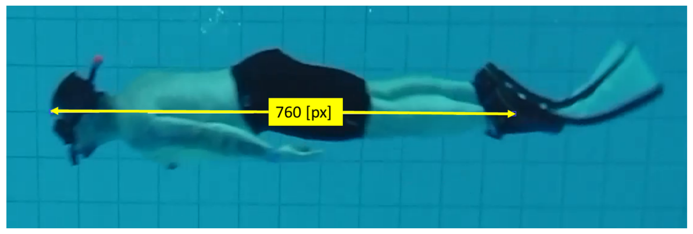
The conversion from pixels to SI units (metres) was carried out for the plane of the diver’s movement shown in
Figure 7, where the swimmer’s height of 1.82 m equals 760 pixels. It can also be used to measure a specific dimension, such as the swimmer’s trunk length or head dimension, but here the swimmers length was used because it had the best length-to-pixel ratio. As a result, the image processing system can be used regardless of the distance between the diver and the camera.
Taking the measurement accuracy into consideration, the presented method has limitations related to the magnitude rises with increasing distance between the diver and the optical axes of the lens. The perspective error can be reduced by using a multi-camera recording system or by calibration dimension in every sequence of the diver’s movement.
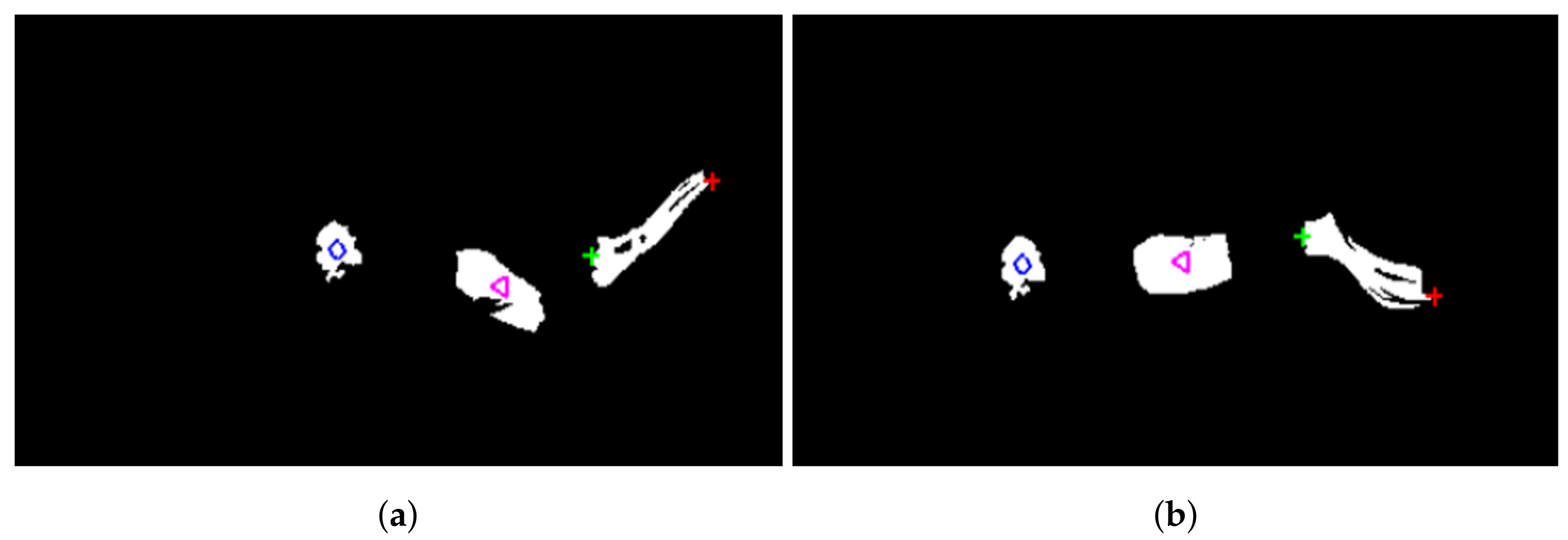
By setting the threshold based on the region of interest, the matrix dimensions were reduced even further. Each matrix cell was tested against the threshold (which ranged from 0 to 255). Thus, all pixels equal to or below the threshold value are set to logical 0, while the rest are put to logical 1. Because each cell in the matrix is recorded with one bit rather than eight bits, this saves memory space and computer power. This is also an essential consideration in the subsequent analysis step based on data filtering. Each frame must be calculated more than two million times throughout the filtration process (1080 × 1920 = 2,073,600). The number of frames recorded is determined by the time of recording and the camera characteristics (fps). The filtration process is required for region extraction and further position calculation (
Figure 8) for every frame of the recording.
The filtering was carried out while treating each frame as a matrix. The filtration parameters were determined experimentally and depend on the quality of the captured frames. The goal of filtering is to keep the fin shape in one region (
Figure 8). Furthermore, the filtration result maintains the original geometry of the fin, particularly the trailing edge, which is required for Strouhal number computations. The morphological dilation and erosion processes [
30] were used to keep the fins in shape while removing the single pixels that were not needed.
5. Results and Discussion
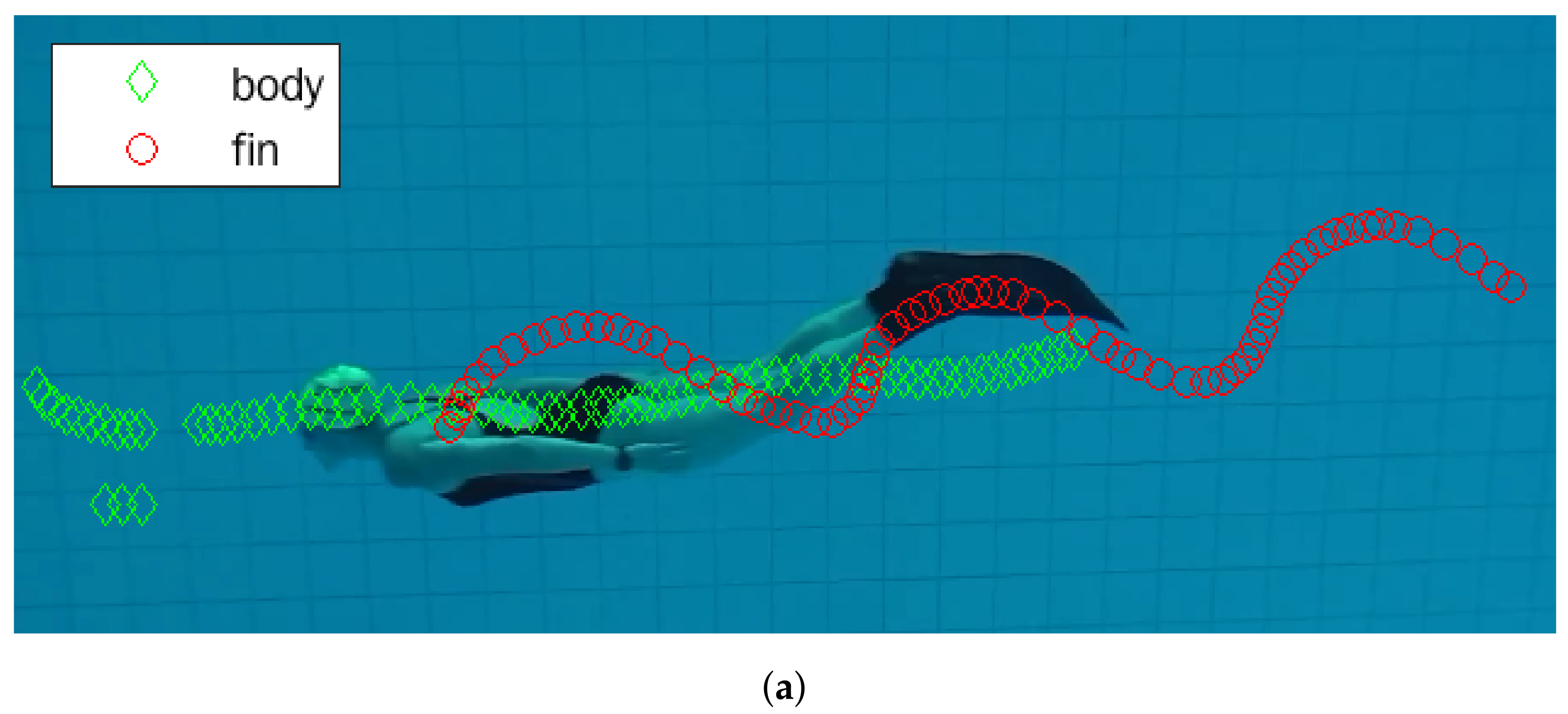
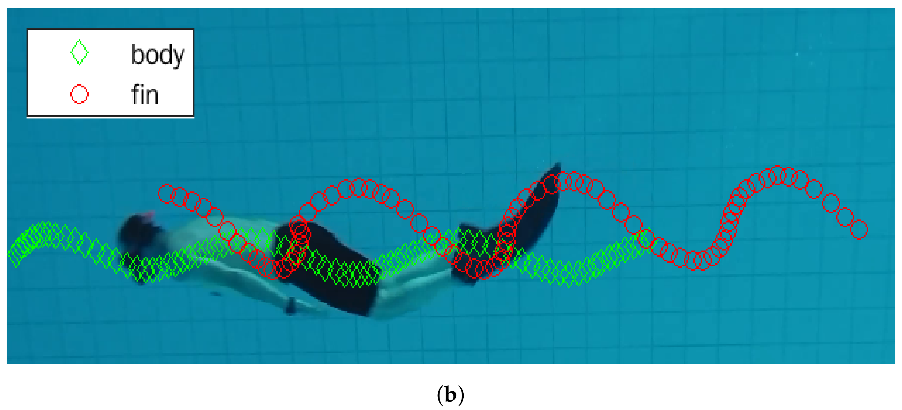
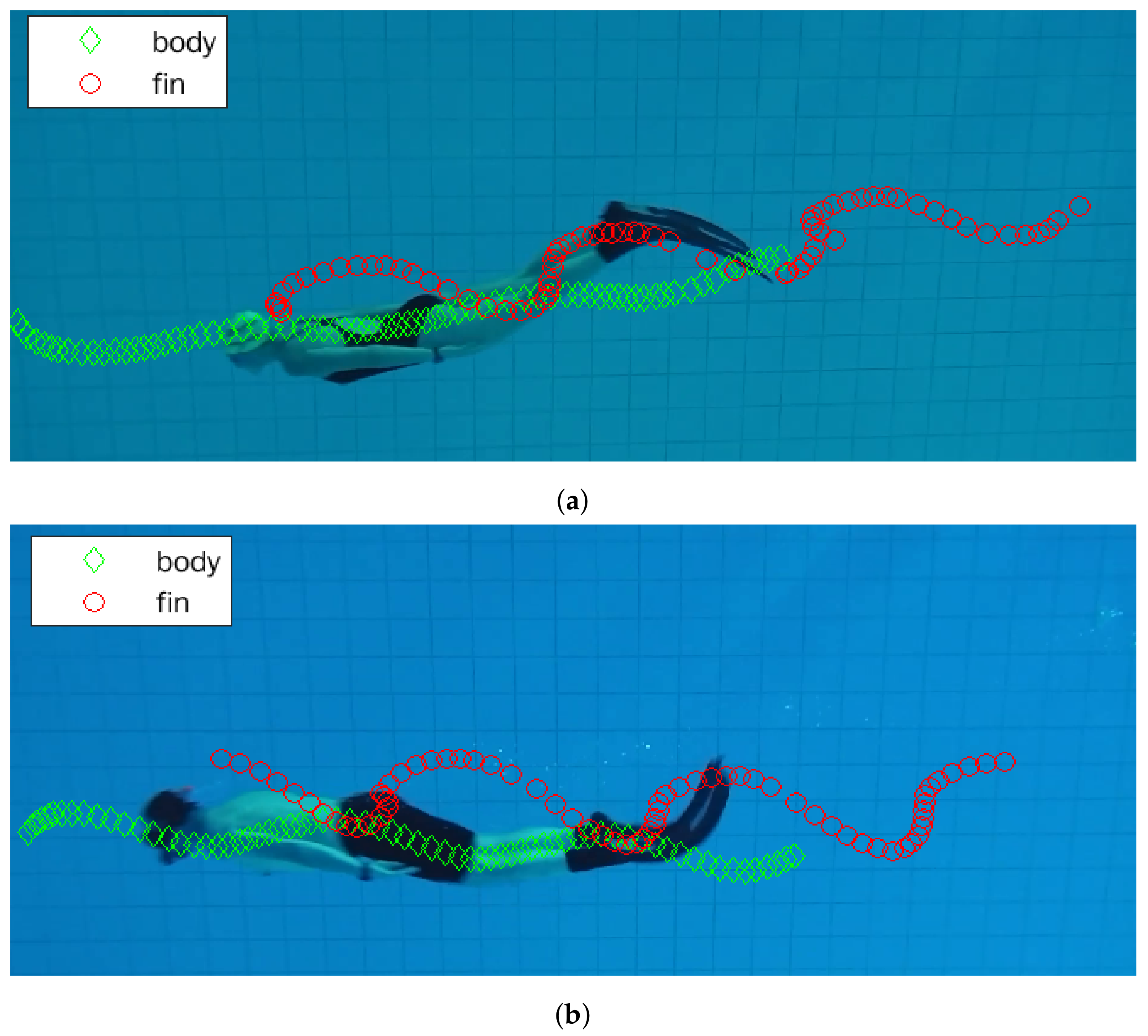
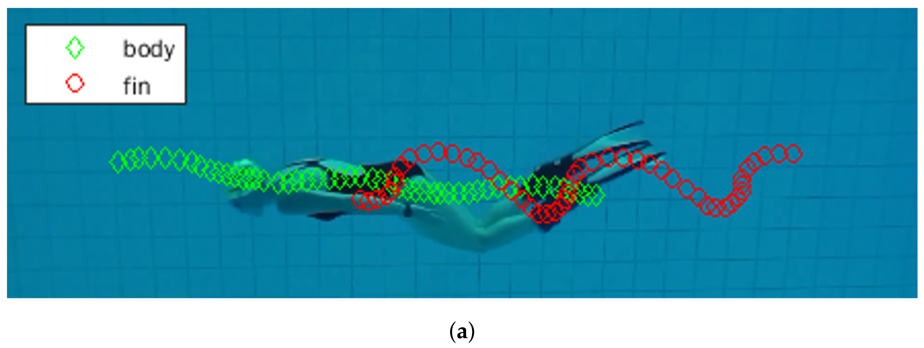
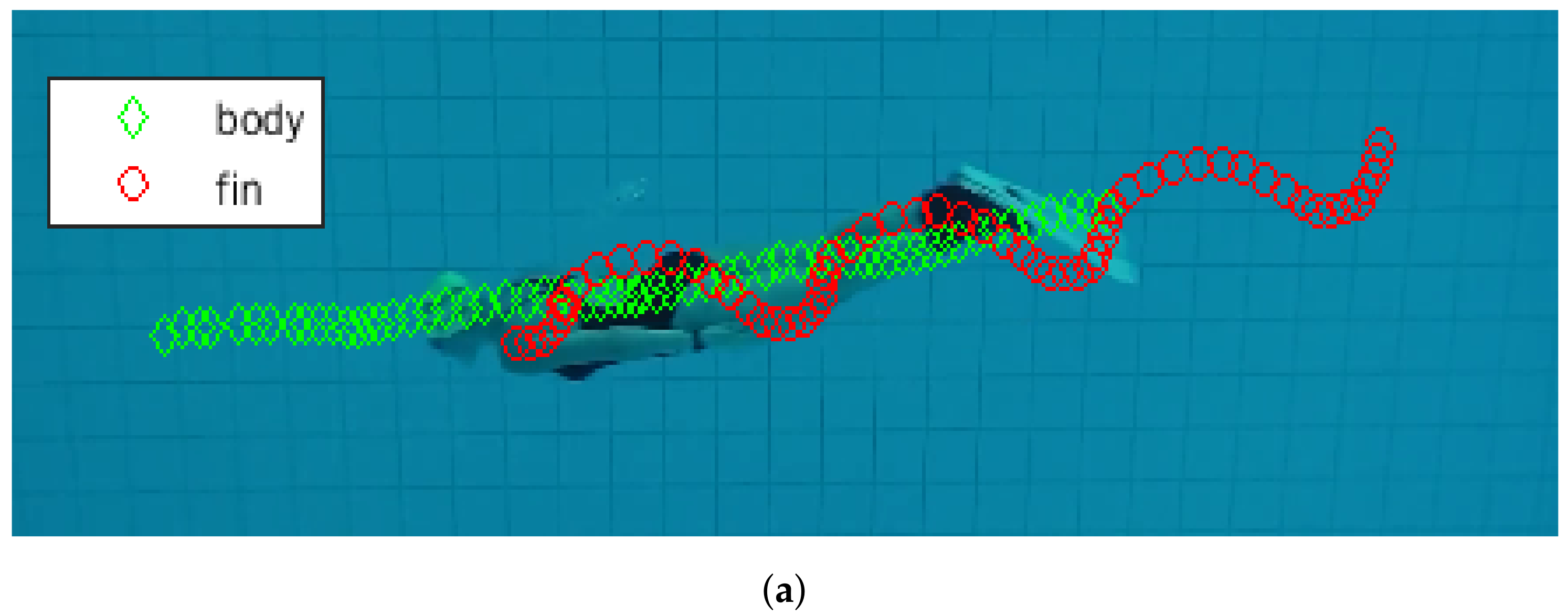
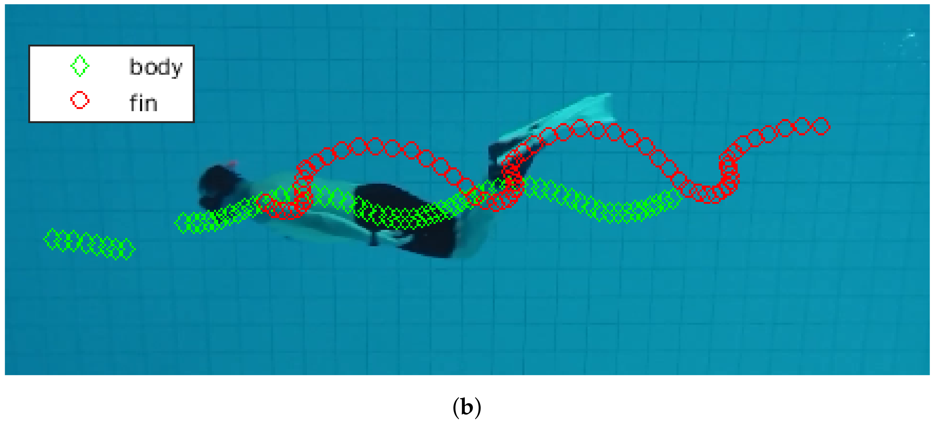
The sequence of swimmer movements are shown in
Figure 9,
Figure 10,
Figure 11,
Figure 12 and
Figure 13 for all tested fins. All fins were tested by both genders, the (a) index refers to female and (b) to male swimmers. The red circle indicates the trajectory of the swimmer’s fins, while the green diamond represents the trajectory of the swimmer’s body.
Figure 9 and
Figure 10 refer to the commercial fins used for comparison, while
Figure 11,
Figure 12 and
Figure 13 refer to the newly designed biomimetic fins. The swimmer’s speed was calculated as the displacement of the swimmer’s body after scaling to the unit of metres for consecutive frames, for a known camera recording frequency.
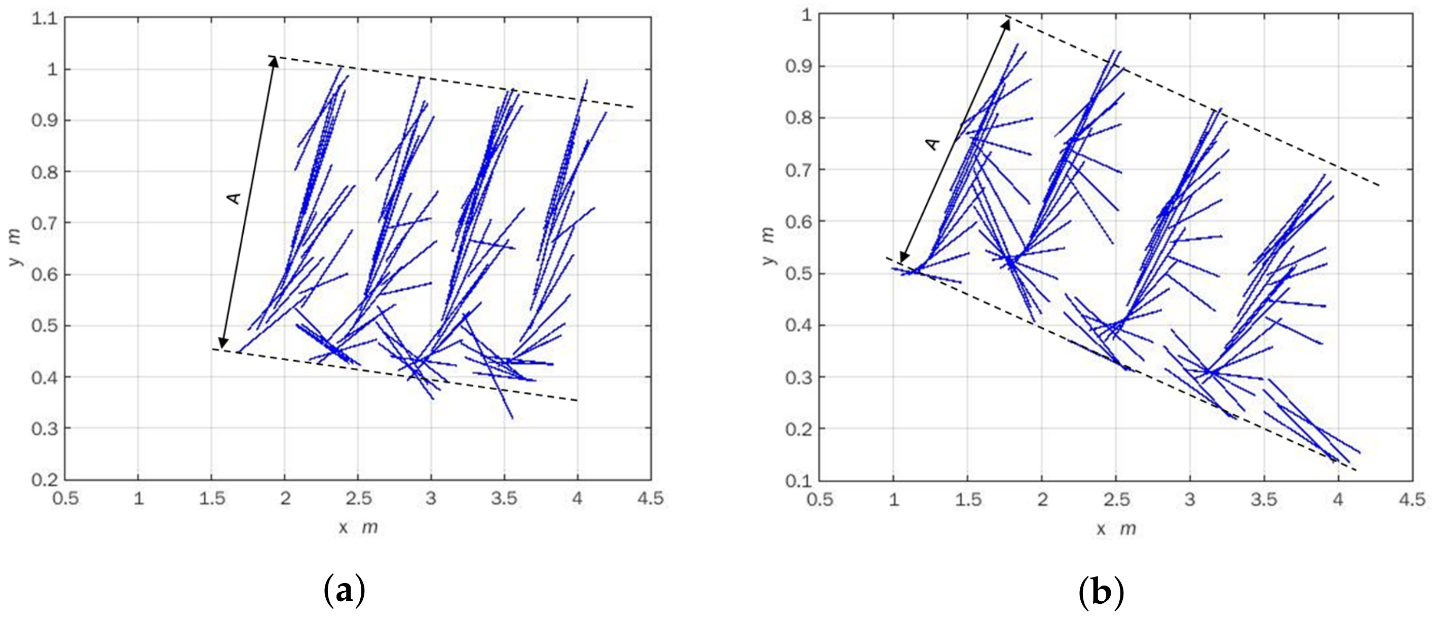
Swimmers do not have to travel horizontally for the fin trailing edge amplitude, as shown in
Figure 14. The mean value of the trailing edge amplitude can be approximated based on the series of the fin oscillations. In
Figure 14, a succession of fin placements is shown as a consequence of the trailing and leading edge calculations. Each line represents the relationship between the leading and trailing edges of each recorded frame. To determine the trailing edge amplitude, the displayed values were scaled from pixels to metres. The swimmer velocity was determined by body movement, and the fin frequency was determined by the centre point of the fins in each frame. The trailing edge estimation at a lower frequency moves slower at the same amplitude (0.43 m). The trailing edge estimation is shown in
Figure 14 for the nonhorizontal direction of swimming.
The Strouhal number was computed using Equation (
4), and the results are shown in
Table 1. The table shows a summary of measured values for five different fins for males and females. The maximum mean velocity value was reached for Aqualung fins (1.38 m/s) for a leg movement frequency of 0.75 Hz and a trailing edge amplitude of 0.43 m. The minimum mean velocity value was reached for biomimetic fin type
B (0.74 m/s) for a leg movement frequency of 0.75 Hz and a trailing edge amplitude of 0.40 m. This is mainly due to the difference in the fin lengths. The biomimetic fin type
B is shorter than Aqualung ones due to these fins (type
B) being designed for rescue tasks intended for boat passengers who are generally not professional swimmers. The biomimetic fin type
B is characterised by a Struhal number that is slightly above the optimal value in comparison to a fish, where the ideal Strouhal number is between 0.2 and 0.4 [
27,
31]. The same biomimetic fins (type
B) achieve a Strouhal number in the optimal range for female swimmers (
). The differences are due to the vertical movement of the male swimmer, as presented in
Figure 12. When the data for biomimetic fin type
B are compared, it can be seen that even though the frequency of the fin movement is higher for males (0.75 Hz) than for females (0.67 Hz), the swimmer with the lower frequency has a higher movement velocity (0.94 m/s) with respect to the male mean velocity (0.74 m/s). This can be explained by the provided image processing algorithm, as seen in the results in
Figure 12a,b, where the differences between the two swimmers can be seen in the vertical direction. In
Figure 12a, the swimmer moves straight, but in
Figure 12b, the swimmer’s body oscillates in a vertical position. The changes cannot be identified using the oxygen consumption method of study, which produces ambiguous results [
14]. The majority of fin performance tests refer to medical assessments for oxygen consumption while swimming in the same settings [
32]. In addition, the measurements made with wire sensors, as given in the paper [
12], do not explain why the disparities occur due to the wire sensors’ ability to measure exclusively along the wire.
The highest mean velocity (1.28 m/s) among biomimetic fins was observed for the test of the male swimmer with fin type . For biomimetic fin type , the Strouhal number was equal to 0.20 (male) and 0.27 (female) for the same amplitude of trailing edge, but for a different frequency of fin movements. The same Strouhal number (equal to 0.20) was calculated for Aqualung fins tested by the female swimmer.
It can be observed that the Strouhal number varies from many factors but the most important conclusion is that, for different styles of swimming and different skills, the Strouhal number for the newly designed fins is in the optimal range.
6. Conclusions
The main goal of this research was to design biomimetic folding fins for a wide range of purposes, including recreational swimming, sports swimming, rescue tasks and underwater work. The different characters of movements were assessed in the analysis of parameters for fin design. The presented analysis is part of the research used to manufacture the new biomimetic folding fins as a supplement to the water tunnel test. In the first stage of the research, a water tunnel was designed and, among the many tested fins, a group was used for the test with professional swimmers. Different types of fins were then selected for testing in the pool, based on the image processing system. The image processing system described in this study was employed for swimmer movement analysis, emphasising the parameters required for the Strouhal number computation, such as fin frequency and the amplitude of the trailing edge and swimmer speed. The noninvasive measurement method can be used with various fins and diver outfits, and the diver does not have to move in a horizontal position. The image processing method can also be used to look at how the fins move for different rib flexibilities and levels of experience of the divers. The Strouhal number was presented for three types of biomimetic fins in comparison with two types of commonly used fins. Both measurements (in the water test tunnel and the swimming pool using the presented method) provide the manufacturer with the information needed to produce the new biomimetic fins. The new biomimetic folding fins are currently for sale.
7. Patents
The biomimetic design of folding fins was patented on 28 January 2016 (US 2016/0023053).
