Article

Multi-Tunnel Triboelectric Nanogenerator for Scavenging Mechanical Energy in Marine Floating Bodies

1
Dalian Key Laboratory of Marine Micro/Nano Energy and Self Powered Systems, Marine Engineering College, Dalian Maritime University, Dalian 116026, China
2
National Key Laboratory of Science and Technology on Micro/Nano Fabrication, Shanghai Jiao Tong University, Shanghai 200240, China
3
Department of Electrical and Computer Engineering, National University of Singapore, Singapore 117576, Singapore
*
Authors to whom correspondence should be addressed.
J. Mar. Sci. Eng. 2022, 10(4), 455; https://doi.org/10.3390/jmse10040455
Submission received: 8 March 2022 / Revised: 21 March 2022 / Accepted: 22 March 2022 / Published: 24 March 2022
(This article belongs to the Section Marine Energy)

Abstract

:
The ocean has an abundant reserve of wave energy, which is considered to be a clean, widely distributed and inexhaustible resource. Triboelectric nanogenerators (TENGs) have been regarded as a reliable technology for harvesting wave energy due to its robustness and efficiency in scavenging random mechanical energy. In this study, a wave energy harvesting multi-tunnel TENG (MT-TENG) has been proposed, which could be integrated easily with ocean buoys. The MT-TENG consists of polytetrafluoroethylene (PTFE) balls and a multi-tunnel frame, which could convert wave energy into electrical energy. The multi-tunnel design also avoids possible mutual obstruction of the PFTE balls during the movement. Compared with the flat type structure, the multi-tunnel structure could enhance output performance obviously. With an agitation frequency of 2 Hz and vibration amplitude of 130 mm, the MT-TENG has a peak power density of 8.3 W/m3, which is five times that of the flat type structure TENG. By integrating with a life buoy and floating pipe line, the MT-TENG could harvest wave energy to light LEDs continuously, which could provide a new solution for maritime rescue and night offshore oil delivery warning.

1. Introduction

The demand for energy is increasing with the global economy. According to the estimated reserves-production ratio in 2019 [1], global coal, natural gas, and oil reserves could supply 132 years, 49.8 years, and 49.9 years, respectively. Energy conservation, emission reduction, and the exploitation of alternative energy sources have become important strategies for sustainable development in the world today [2]. Among the renewable energy sources, environmental mechanical motions have low frequency (less than 10 Hz) and random characteristics [3]. The environmental mechanical energy exists in most natural phenomenon, such as in waves, tides, and human movement [4,5]. It is estimated that the global wave power potential could reach 3.7 TW, which is in the order of magnitude of the world consumption of electrical energy [6]. Wave energy has the advantages of wide distribution as well as relatively high energy density [7]. Actually, it is considered as a promising renewable energy source [8]. In terms of wave energy harvesting, conventional ocean wave energy harvesters consist of floating buoy and electromagnetic generators (EMGs), which means considerable costs and more complex structures [9]. Many wave energy devices harvest wave energy through expensive bracing or mooring systems to ensure the equipment survives extreme weather [10]. Another method of harvesting wave energy is to combine the wave energy device with an ocean buoy and floating pipeline, thereby reducing costs. As for conventional wave energy devices, energy conversion relies on the EMG. The metal coils and magnets of the EMG will corrode due to the humid environment at sea [7].
A triboelectric nanogenerator (TENG), based on the coupling of contact electrification and electrostatic induction, could effectively harvest various irregular mechanical energy in the environment [11,12], it has the advantages of low cost, light weight and high energy efficiency. TENG could harvest energy from waves [11,12,13,14,15,16,17,18,19], wind [20,21], human motion [22,23], object vibration [24] and even sound vibration [25]. Due to the sensitivity of TENG to the external stimulus, TENG could also be used for self-powered sensing [26,27,28]. In terms of self-powered sensing, many studies have shown that TENG could be used for two-phase flow [29], liquid level changes [30,31], trajectory-tracking [32], wearable sensing [33,34,35], health monitoring [36,37] even liquid leakage inspection [38]. Compared to traditional EMG, TENG has the incompatible efficiency for harvesting low-frequency (<3 Hz) wave energy [39,40,41], so that it has unique advantages for exploration of blue energy, which has the potential to be utilized in the field of seafarers rescue and marine warning.
In order to harvest various form of renewable mechanical energy such as wave energy, wind energy, vibration energy and biological kinetic energy more efficiently, many studies on structural design, material treatment and system optimization have been carried out [7,8,9,10,11,12,13,14,15,16,17,25,27]. Yin et al. developed multi-plate structured TENG for harvesting hydro energy [42], the output is improved by a parallel process of multiple TENGs. Zhang et al. have presented a multi-grating TENG for ocean wave energy harvesting [43], which harvest the wave flapping energy. In the past, many TENG that harvested wave energy used balls as friction materials [11,12,13,16]. Wang et al. developed a totally sealed spherical structure for scavenging random low-frequency wave energy [44], in order to float on the surface of water, its internal space is large. Pang et al. have presented a multi-layer nesting TENG by nesting the assembly of multiple smaller-sized shells [13]. Ahmed et al. proposed a salter duck structure TENG for harvesting wave energy [45]. Wang et al. developed a sandwich-like TENG, the parallel connected unit could increase electrical output obviously [12]. The studies mentioned above mainly optimized the spatial structure of the TENG for harvesting wave energy, and the latter several TENGs used balls and metal electrodes as friction materials. However, the distribution of balls in these TENG is relatively scattered, and there are often ineffective motions during rolling motion, resulting in low energy efficiency and space waste.
In this paper, we present a new type of multi-tunnel structure triboelectric nanogenerator (MT-TENG) that could be used to scavenge wave energy. The compact structure of the MT-TENG increases the contact area between the PTFE balls and copper electrodes. The multi-tunnel design also avoids the possible mutual obstruction of the PFTE balls during the movement, which means that they could shuttle between the two copper electrodes more along the tunnel instead of wandering in the single copper electrode, thus effectively improving the power generation efficiency. Compared to the flat type TENG, the multi-tunnel structure TENG increases the output current, transferred charge and power density by approximately two times, four times and five times, respectively. By integrating with a life buoy and floating pipe line, the MT-TENG could harvest wave energy to light LEDs continuously, which could provide a cost-efficient beacon in night time marine operations, especially maritime rescue.

2. Results and Discussion

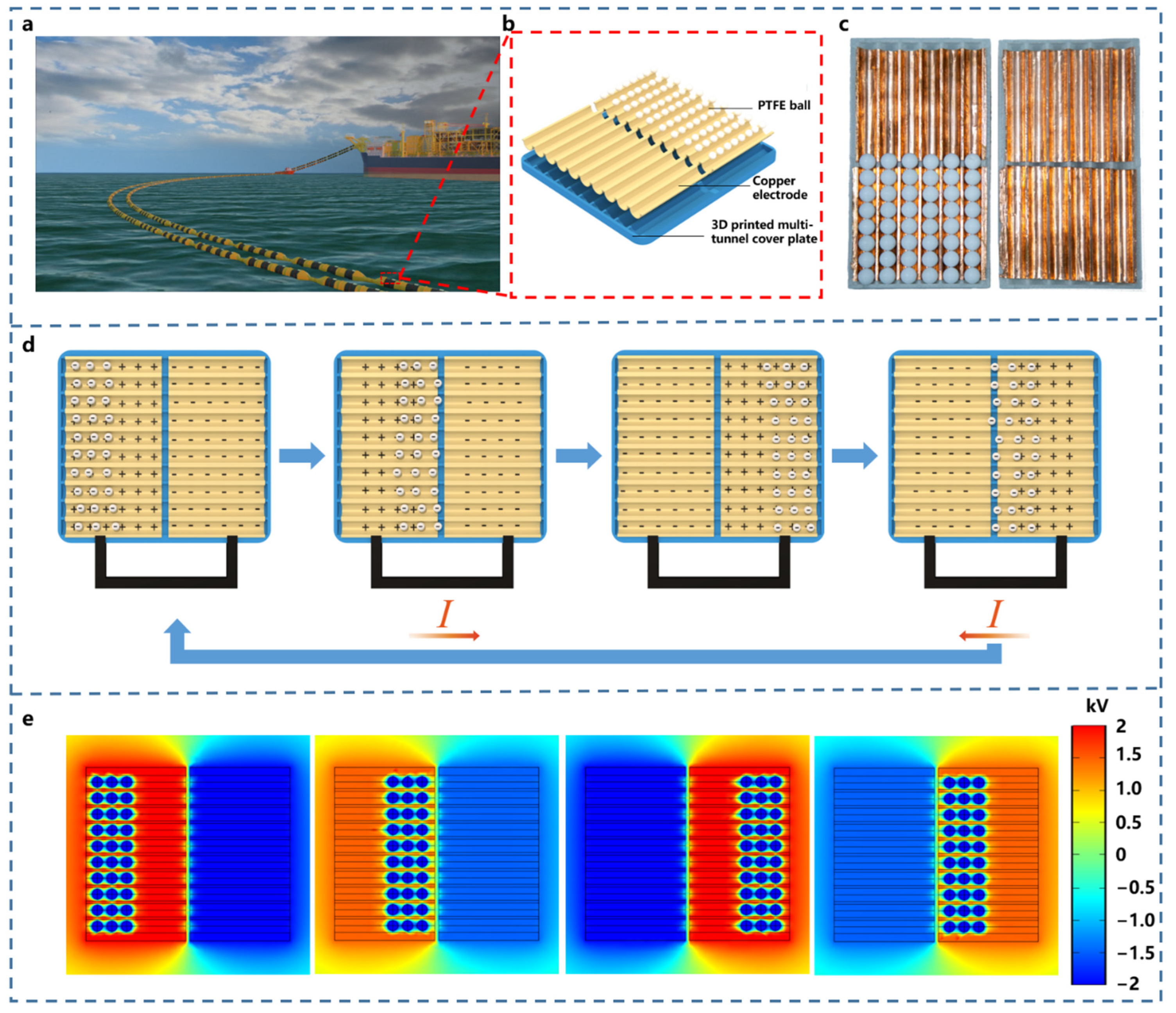
2.1. Design and Working Principle of the MT-TENG

As shown in Figure 1a, the application scenario of the MT-TENG integrated floating pipeline for night offshore oil delivery warning is demonstrated. Figure 1b shows multi-tunnel internal structured design that consists of a cover plate, PTFE balls and copper electrodes. The MT-TENG is composed of PTFE balls and two cover plates with copper electrodes attached. The cover plates fabricated by three-dimensional (3D) printing is designed with multiple semi-cylindrical grooves, two copper electrodes are closely attached to the cover plates along the grooves, and the two cover plates form a tunnel for balls rolling motion. The physical map of the MT-TENG is shown in Figure 1c. The MT-TENG with 6-tunnel structure has a cover plate of 160 mm long and 90 mm wide (about per tunnel 15 mm). Compared with the flat type structure TENG (see Figure S1), the multi-tunnel structure TENG could reduce the ineffective motion of the PTFE balls, and the compact structure would increase the contact area with the friction material. Thus, multi-tunnel structure could enhance the output performance.
The free-standing working principle of the MT-TENG is shown in Figure 1d. Under wave excitation, the PTFE balls could reciprocate along its tunnel. After multiple contacts with two sets of copper electrodes, the PTFE balls will generate electric potential due to the contact electrification. The electronegativity of PTFE is much higher than that of copper. The PTFE balls will become negatively charged due to the contact electrification. Since the PTFE material is electret, the charge will remain on its surface [46]. Due to the electrostatic induction, when the PTFE balls roll to the right, the right electrode induces a positive charge, and electrons are transferred from the right to the left along the circuit to maintain electrostatic balance. When the PTFE balls roll in the opposite direction, the left electrode induces a positive charge. The current in the opposite direction is generated in circuit. As the PTFE balls roll back and forth, alternating current is generated in the loop. The COMSOL Multiphysics software was used to simulate the electrical potential distribution of the MT-TENG in various motion states by AC/DC modules as shown in Figure 1e.
According to the theory of the sliding-mode freestanding TENG [44,47,48], the governing equation for the MT-TENG could be written as [47]:
V o c = Q s c C
where Voc is the output voltage, and C stands for capacitance. The capacitance C is nearly constant due to the stationary electrodes in the MT-TENG. A large open-circuit voltage could be generated from the MT-TENG due to the relatively small inherent capacitance C. According to the theory of the rolling-type freestanding mode TENG, the MT-TENG could be regarded as an almost constant capacitor [47].
The short-circuit current (Isc) is the transferred charge quantity (Qsc) divided by rolling time, which could be illustrated as [44]:
I s c = Q s c d t = d Q s c d x d x d t = d Q s c d x v
The short-circuit current Isc also relies on the external motion speed changes.

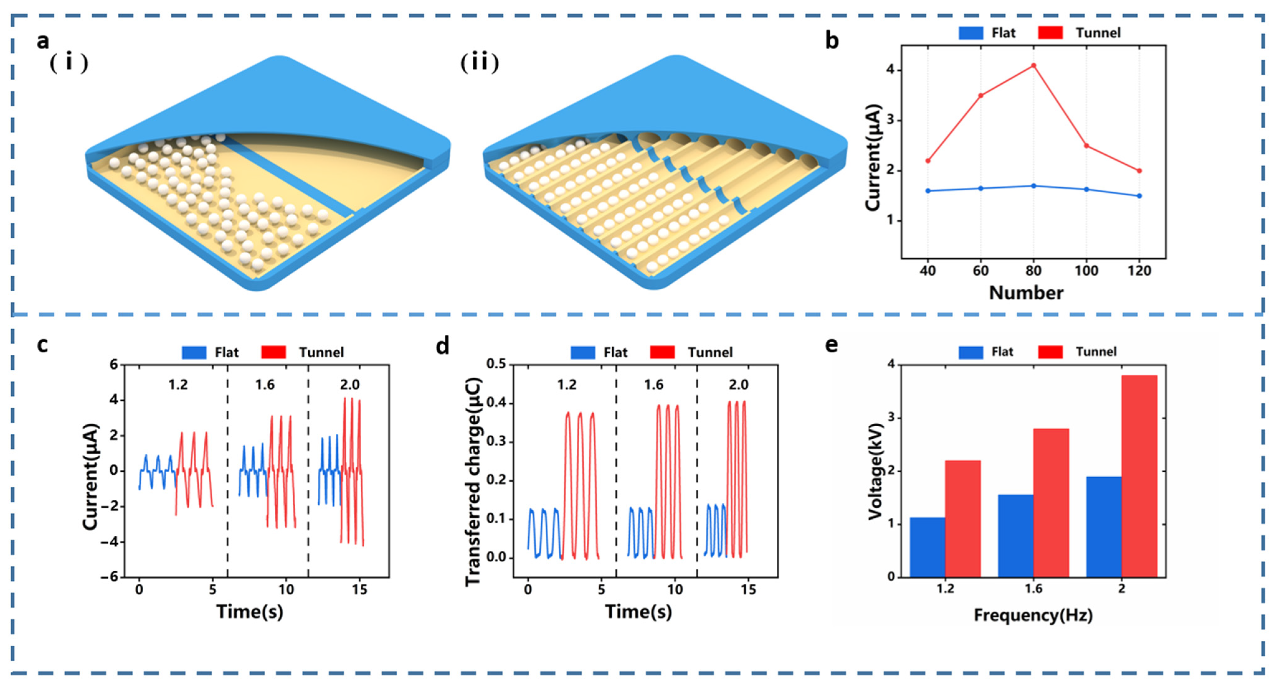
2.2. Comparison of the Flat Type TENG and the Multi-Tunnel TENG and Effect of the Parameters of PTFE Balls on Output Performance of the MT-TENG

In order to prove that the multi-tunnel structure is more efficient, this work compared the output performance between the MT-TENG and the flat type TENG. In comparison, the MT-TENG uses a 10-tunnel structure and maintains the same 80 balls with a diameter of 10.5 mm in the two TENGs. As for the MT-TENG, each tunnel has eight PTFE balls. The detailed output of the MT-TENG for PTFE balls with various diameters could be found in Figure S2. As shown in Figure 2a, partial cross-sectional views of the flat type TENG and multi-tunnel TENG show the internal structure. Figure 2b shows that with the change in the number of PTFE balls, both TENGs could reach the maximum output at 80 balls, however, it is obvious that the current output of the MT-TENG has always been higher than the current output of the flat type TENG. The detailed outputs of the flat type TENG and the MT-TENG, depending on the number of the PTFE balls, can be seen in Figures S3 and S4. In the experiment, the linear motor control frequency was varied from 1.2 Hz to 2.0 Hz and the amplitude was kept unchanged at 130 mm. As shown in Figure 2c,d, the peak value short circuit current Isc of the MT-TENG is 4.1 μA, and the peak value of short circuit transferred charge Qsc is 0.42 μC is about twice and quadruple that of the flat type TENG, respectively. It is worth mentioning that the voltage of the MT-TENG exceeds the measurement range of the electrometer (Keithley 6514), therefore the voltage probe (HVP40) is used to measure the open circuit voltage and the unit is kV. The open-circuit voltage of the MT-TENG is nearly twice that of the flat type TENG, as Figure 2e shows.
The multi-tunnel structure has higher and more stable output performance than the flat type TENG. In the case of more than 80 balls, due to the mutual obstruction effect among the PTFE balls, the PTFE balls tend to wander within a single electrode instead of reciprocating between two electrodes under external excitation. This trend does not generate electrical output, so it is an invalid movement. Multi-tunnel structure TENG enables the PTFE balls to reciprocate in their respective tunnel in an orderly manner, effectively avoiding the mutual obstruction effect caused by multiple balls rolling simultaneously.

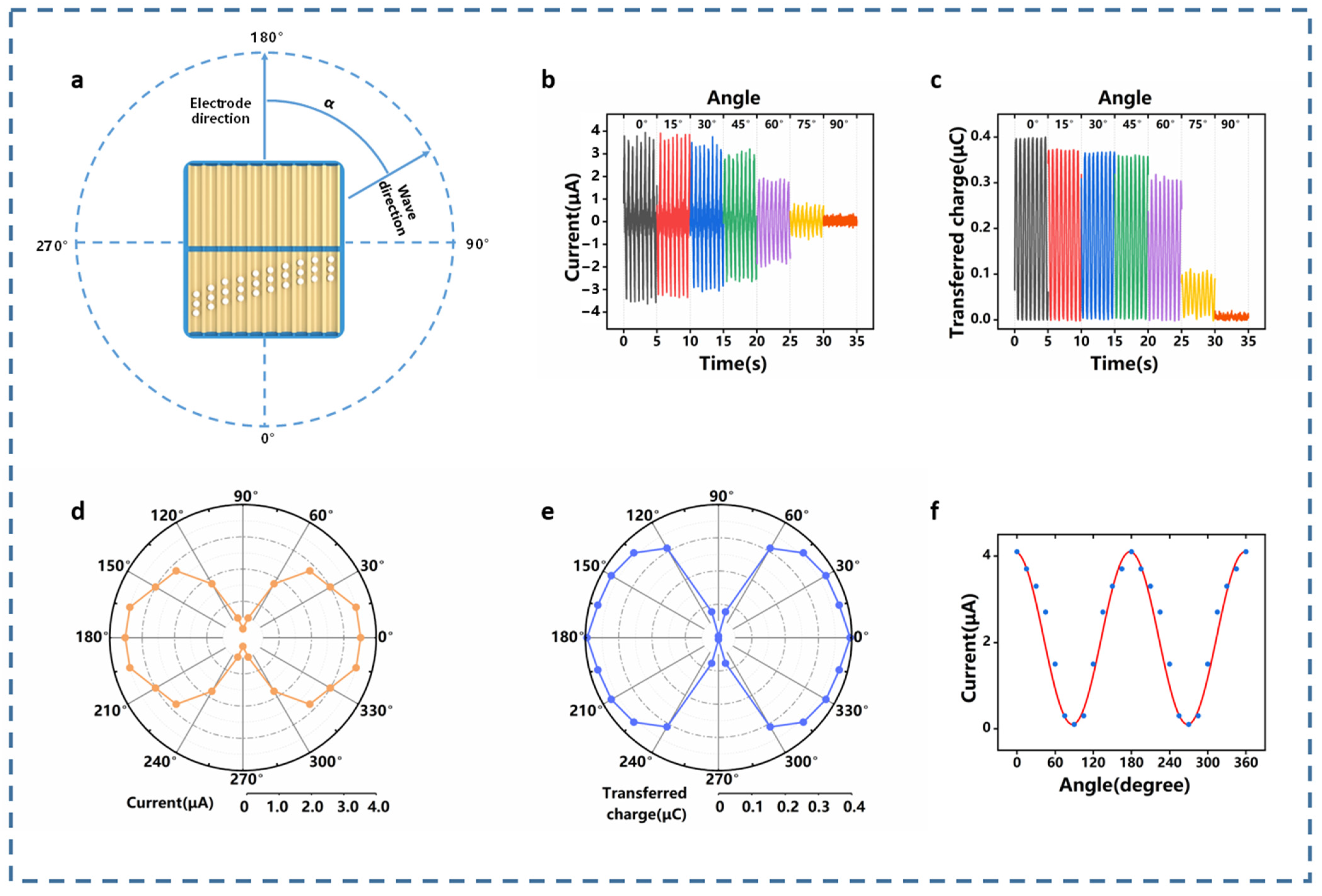
2.3. Output Performance of the MT-TENG under Various Wave Condition

In this section, in order to simulate different operating conditions of waves, a linear motor is used to precisely adjust the frequency and amplitude of the motion, so as to study the output performance of the MT-TENG (10-tunnel) as shown in Figure 3a. The frequency varies from 0.4 Hz to 2 Hz and the amplitude varies from 50 mm to 130 mm. The details of short circuit current and short circuit transferred charge changes could be found in Figures S5 and S6, and a part of the data is selected for display as shown in Figure 3b–f. In Figure 3b,c, Isc and Qsc are measured by changing the frequency while keeping the amplitude at 130 mm. Obviously, it could be seen that the current and charge output are positively correlated with increasing frequency. With the continuous contact of the PTFE balls and electrode, the charge generated on the PTFE balls and electrode will eventually reach a saturated state. According to I = dQ/dt, high wave frequency results to the high output current when the transferred charge reaches the maximum value. Thus, the change of the transferred charge and the output current at different frequencies is different. Similarly, in the Figure 3d,e, keeping the frequency at 2 Hz and changing the amplitude, the current and charge output are also positively correlated. The peak values of Isc and Qsc were obtained at a frequency of 2 Hz and an amplitude of 130 mm, which were 4.1 μA and 0.42 μC, respectively. Under lower frequency conditions (lower than 0.4 Hz), the PTFE ball could hardly perform complete motion in their respective tunnels, so the output signal is extremely low. A higher amplitude indicates more energy and, as such, the output performance will also increase. The current output peak values of the MT-TENG under different operating conditions are made into a three-dimensional histogram, as shown in Figure 3f, which more intuitively shows that the output performance of the MT-TENG is positively correlated with the motion frequency and amplitude. Sorting the peak values of these details data into a data map (Figure S7), it could be seen that as the motion becomes more intense, the output of the MT-TENG tends to be flat, indicating that the MT-TENG is adaptable for scavenging low-frequency wave energy.
The direction of the external excitation is not always along the direction of the tunnel (i.e., the direction of the electrode). They often have an angle between them. As shown in Figure 4a, α is defined as the angle between the external excitation direction and the electrode direction. As the angle α changes, the output performance of the MT-TENG will also change significantly. The output performance at different angles α is shown in Figure 4b,c, it could be clearly seen that the output performance reaches its peak when the angle α is 0°. As the angle α gradually increases, the short circuit current Isc and the short-circuit charge Qsc gradually decrease. When the angle α reaches 90°, there is basically no output. As shown in Figure 4d,e, the directional map could clearly show the output performance change of the MT-TENG, with the angle α change, and shows periodicity. Through the nonlinear curve fitting of the origin software, the data of the short circuit current is fitted into a periodic curve (see in Figure 4f), the equation is as follows:
I = α + A sin 2 ( π α + b ω )
where A is determined to the frequency and amplitude of the motion. After fitting, it is calculated that the values of coefficients for A and b are four and 93.75. It could be known from Equation (3) that the short circuit current Isc depends on the angle α when the frequency and amplitude are determined. As shown in Supporting Table S1, some previous wave energy harvesting TENGs are summarized. The performance of the MT-TENG is not inferior in low wave frequency and mild sea conditions.

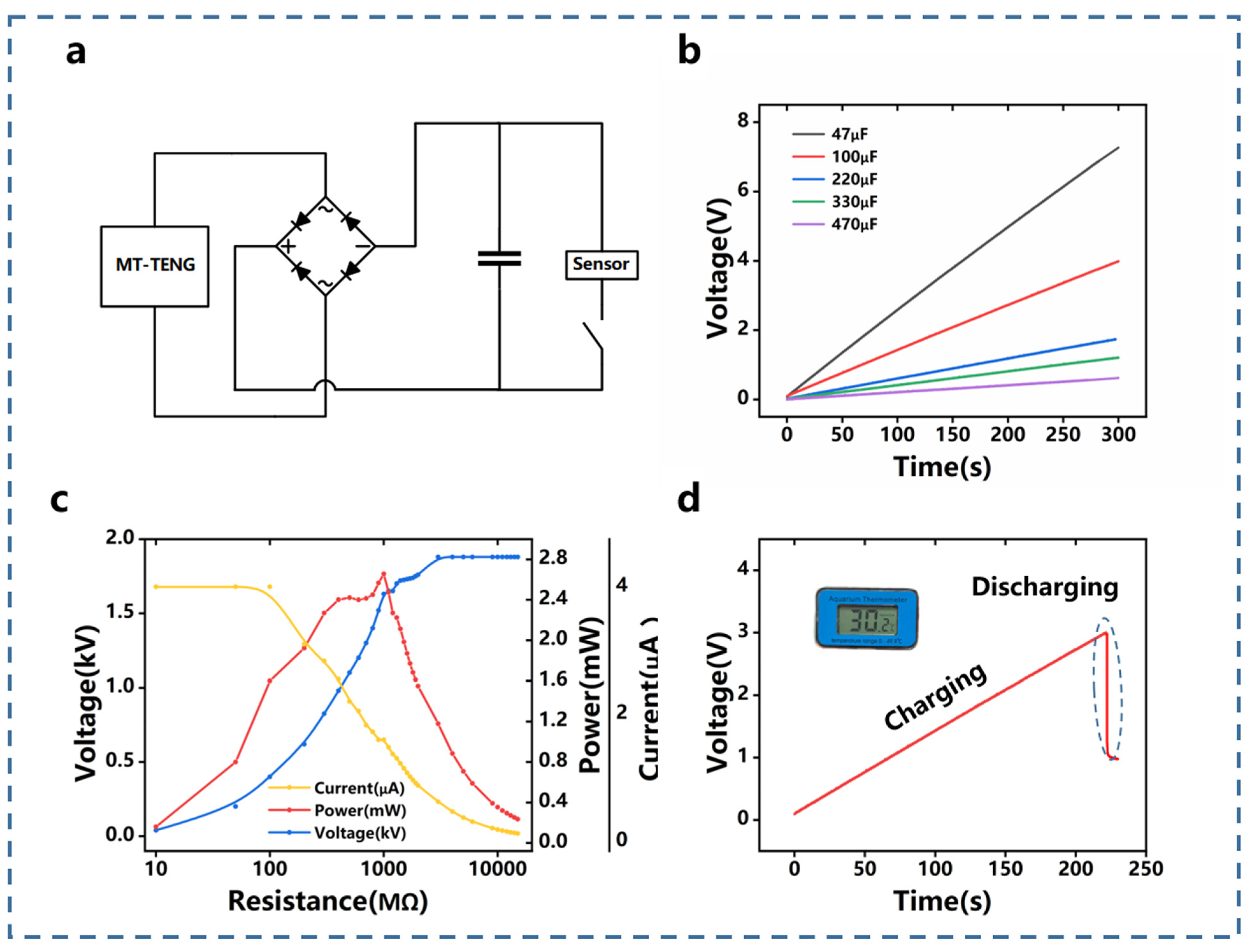
2.4. Output Performance of the Multi-Tunnel TENG for Powering Electronics

The multi-tunnel TENG could harvest low-frequency energy after passing through the rectifier circuit to charge the capacitor and supply power to the electronic devices. Figure 5a is the equivalent circuit of the rectifier circuit. The charging performance of the MT-TENG to the capacitor is shown in Figure 5b. The MT-TENG used in this section is a 10-tunnel structure and maintains a frequency and amplitude of 2 Hz and 130 mm. It could be concluded that a 47 μF capacitor could be charged to 7.7 V in 300 s. As the capacitance increases, the charging rate decreases significantly. For the largest 470 μF capacitor used, it could be charged to 0.2 V in 300 s.
As shown in Figure 5c and Figure S8, the output voltage, current and output power of the MT-TENG and the flat type TENG under different loads are measured. In the measurement, a voltage probe is used to measure the voltage of the load, and then the current value is calculated by Ohm’s law combined with the load resistance. When the output power of the MT-TENG reaches the maximum, the external load is equivalent to the internal resistance. The peak power of the MT-TENG is 2.7 mW when the external load is 1000 MΩ, and peak power of the flat type TENG reaches 0.52 mW when the external load is 600 MΩ. Figure 5d shows the voltage change during the charging of the capacitor. A 100 μF capacitor is used as an energy storage element. Under the condition of 2 Hz frequency and 130 mm amplitude, the voltage on both sides of the capacitor reaches 3 V after 220 s, and then the thermometer is successfully lit up.

2.5. Demonstration of Multi-Tunnel TENG

To show the potential of the MT-TENG in harvesting wave energy, two demonstrations of the life buoy (Video S1) and floating pipeline (Video S2) are carried out. The MT-TENG used in the demonstration has 10 tunnels. According to previous research, 80 PTFE balls with a diameter of 10.5 mm are used here, with eight balls per tunnel. In order to enable the MT-TENG to better integrate with the life buoy and floating pipeline, a folding structure is adopted. The three-dimensional size of this structure is 160 mm long, 75 mm wide and 28 mm high. This design will not affect its output performance. The photograph of its appearance is shown in Figure 6a, and the specific design is shown in Figure S9. Each MT-TENG was connected to a rectifier bridge to power 30 LEDs. The rectifier bridge could make the PTFE balls move back and forth once, while LEDs light up twice. The life buoy and floating pipeline could integrate with the MT-TENGs, as shown in Figure 6b,c. Driven by the wave, 30 LEDs per MT-TENG unit could be illuminated, see in Figure 6d,e. Through its concise mechanism and compact structure, the output current of the MT-TENG remains consistent within three days, showing its robustness (Figure 6f).

3. Methods

3.1. Fabrication of the MT-TENG

The multi-tunnel cover plates are printed with UV resin, this UV resin material comes from the DSM (Royal DSM N.V.) company. This multi-tunnel structure was modeled by Solidworks, and then printed using a resin printer. The thickness of the two copper foils is up to 50 μm and they are closely attached along the groove in parallel. Various diameters of PTFE balls were purchased from Shanghai Daoguan Hardware Rubber Plastic Hardware Co., Ltd. MT-TENG uses a thermoplastic film and epoxy coating method for sealing and waterproofing in order to be flexible in combination with life buoy and floating pipeline.

3.2. Electrical Measurement of the MT-TENG

In order to measure the electrical output performance of the MT-TENG, an electrometer (Keithley 6514) is used to measure the short circuit current Isc, the short circuit charge Qsc and open circuit voltage Voc (via voltage probe HVP40). The adjustable linear motor (US-52) is used to simulate the external excitation and could precisely adjust the various parameters of the movement. A variety of capacitors with different capacities are used to evaluate the charge and discharge performance of the MT-TENG, among which a 100 μF capacitor is used to power the temperature sensor.

4. Conclusions

In this work, we propose a multi-tunnel structure triboelectric nanogenerator as wave energy harvester. The multi-tunnel TENG (MT-TENG) were fabricated with two cover plates, two sets of copper electrode and PTFE balls. The cover plates have many semi-cylindrical grooves. The two cover plates are combined to form many tunnels for the movement of the PTFE balls. This MT-TENG could effectively harvest wave energy through the wave-induced rolling of the PTFE balls. The output performance of the MT-TENG with 10 tunnels has been studied. The linear motor is used to simulate various wave conditions, the effect of the diameter and number of PTFE balls, the frequency and amplitude of motion and the angle between the wave direction and the tunnel direction on the output performance has been systematically studied. The results show that the multi-tunnel structure could actually improve its output performance.
The MT-TENG could drive electronic devices and charge energy storage unit. The multi-tunnel design proposed in this work provides an effective wave energy harvesting strategy. Considering that the MT-TENG shows major advantages in structure, space utilization and ease of integration, low-frequency wave energy could be effectively harvested and applied to seafarers rescue and marine warning.

Supplementary Materials

The following supporting information can be downloaded at: https://www.mdpi.com/article/10.3390/jmse10040455/s1, Figure S1: Photograph of the flat type TENG; Figure S2: Detailed outputs of the MT-TENG for PTFE balls with various diameter; Figure S3: Detailed outputs of the flat type TENG with 40, 60, 80, 100, 120 balls; Figure S4: Detailed outputs of the MT-TENG with 40, 60, 80, 100, 120 balls; Figure S5: Details of short-circuit current with various frequency and amplitude; Figure S6: Details of transferred charge with various frequency and amplitude; Figure S7: Details of transferred charge with various frequency and amplitude; Figure S8: The output voltage, current and output power for the flat type TENG on the resistance of the load; Figure S9: Photographs of the folding structure of the MT-TENG (a) Two cover plates and intermediate frame. (b) Intermediate frame combined with one cover plate. (c) Intermediate frame combined with two cover plates; Table S1: Some wave energy harvesting TENGs comparison; Video S1: Application of the MT-TENG integrating with life buoy; Video S2: Application of the MT-TENG integrating with floating pipeline.

Author Contributions

Conceptualization, Z.Z. and Z.H.; investigation, Y.W. (Yan Wang); data curation, Z.Z. and D.L.; writing-original draft preparation, Z.Z. and Z.H.; writing-review and editing, H.W. and M.X.; visualization, Y.W. (Yawei Wang) and Q.Z.; supervision, M.X. All authors have read and agreed to the published version of the manuscript.

Funding

The work was supported by the National Key R & D Project from Minister of Science and Technology (2021YFA1201604), the National Natural Science Foundation of China (Grant Nos. 51879022, 52101382), Project of Dalian Outstanding Young Scientific and Technological Personnel (2021RJ11), Innovation Group Project of Southern Marine Science and Engineering Guangdong Laboratory (Zhuhai) (No. 311021013), China Scholarship Council (CSC No. 202006570022).

Institutional Review Board Statement

Not applicable.

Informed Consent Statement

Not applicable.

Data Availability Statement

Data is available on request from the authors.

Conflicts of Interest

The authors declare no conflict of interest.

References

  1. BP Energy Statistical Review of World Energy Globally Consistent Data on World Energy Markets and Authoritative Publications in the Field of Energy. BP Energy Outlook 2021 2021, 70, 8–20.
  2. Chu, S.; Majumdar, A. Opportunities and Challenges for a Sustainable Energy Future. Nature 2012, 488, 294–303. [Google Scholar] [CrossRef]
  3. Zi, Y.; Guo, H.; Wen, Z.; Yeh, M.H.; Hu, C.; Wang, Z.L. Harvesting Low-Frequency (<5 Hz) Irregular Mechanical Energy: A Possible Killer Application of Triboelectric Nanogenerator. ACS Nano 2016, 10, 4797–4805. [Google Scholar] [CrossRef]
  4. Kulah, H.; Najafi, K. An Electromagnetic Micro Power Generator for Low-Frequency Environmental Vibrations. In Proceedings of the 17th IEEE International Conference on Micro Electro Mechanical Systems. Maastricht MEMS 2004 Technical Digest, Maastricht, The Netherlands, 25–29 January 2004; pp. 237–240. [Google Scholar]
  5. Curto, D.; Franzitta, V.; Guercio, A. Sea Wave Energy. A Review of the Current Technologies and Perspectives. Energies 2021, 14, 6604. [Google Scholar] [CrossRef]
  6. Mork, G.; Barstow, S.; Kabuth, A.; Pontes, M.T. Assessing the Global Wave Energy Potential. In Proceedings of the International Conference on Offshore Mechanics and Arctic Engineering, Shanghai, China, 6–11 June 2010; Volume 49118, pp. 447–454. [Google Scholar]
  7. Wang, Z.L.; Jiang, T.; Xu, L. Toward the Blue Energy Dream by Triboelectric Nanogenerator Networks. Nano Energy 2017, 39, 9–23. [Google Scholar] [CrossRef]
  8. Clément, A.; McCullen, P.; Falcão, A.; Fiorentino, A.; Gardner, F.; Hammarlund, K.; Lemonis, G.; Lewis, T.; Nielsen, K.; Petroncini, S.; et al. Wave Energy in Europe: Current Status and Perspectives. Renew. Sustain. Energy Rev. 2002, 6, 405–431. [Google Scholar] [CrossRef]
  9. Falcão, A.F.d.O. Wave Energy Utilization: A Review of the Technologies. Renew. Sustain. Energy Rev. 2010, 14, 899–918. [Google Scholar] [CrossRef]
  10. Chen, B.; Ning, D.; Liu, C.; Greated, C.A.; Kang, H. Wave Energy Extraction by Horizontal Floating Cylinders Perpendicular to Wave Propagation. Ocean Eng. 2016, 121, 112–122. [Google Scholar] [CrossRef]
  11. Xu, M.; Zhao, T.; Wang, C.; Zhang, S.L.; Li, Z.; Pan, X.; Wang, Z.L. High Power Density Tower-like Triboelectric Nanogenerator for Harvesting Arbitrary Directional Water Wave Energy. ACS Nano 2019, 13, 1932–1939. [Google Scholar] [CrossRef]
  12. Wang, H.; Fan, Z.; Zhao, T.; Dong, J.; Wang, S.; Wang, Y.; Xiao, X.; Liu, C.; Pan, X.; Zhao, Y.; et al. Sandwich-like Triboelectric Nanogenerators Integrated Self-Powered Buoy for Navigation Safety. Nano Energy 2021, 84, 105920. [Google Scholar] [CrossRef]
  13. Pang, Y.; Chen, S.; Chu, Y.; Wang, Z.L.; Cao, C. Matryoshka-Inspired Hierarchically Structured Triboelectric Nanogenerators for Wave Energy Harvesting. Nano Energy 2019, 66, 104131. [Google Scholar] [CrossRef]
  14. Liu, W.; Xu, L.; Bu, T.; Yang, H.; Liu, G.; Li, W.; Pang, Y.; Hu, C.; Zhang, C.; Cheng, T. Torus Structured Triboelectric Nanogenerator Array for Water Wave Energy Harvesting. Nano Energy 2019, 58, 499–507. [Google Scholar] [CrossRef]
  15. Wen, X.; Yang, W.; Jing, Q.; Wang, Z.L. Harvesting Broadband Kinetic Impact Energy from Mechanical Triggering/Vibration and Water Waves. ACS Nano 2014, 8, 7405–7412. [Google Scholar] [CrossRef]
  16. Zhang, S.L.; Xu, M.; Zhang, C.; Wang, Y.C.; Zou, H.; He, X.; Wang, Z.; Wang, Z.L. Rationally Designed Sea Snake Structure Based Triboelectric Nanogenerators for Effectively and Efficiently Harvesting Ocean Wave Energy with Minimized Water Screening Effect. Nano Energy 2018, 48, 421–429. [Google Scholar] [CrossRef]
  17. Wang, Y.; Nazar, A.M.; Wang, J.; Xia, K.; Wang, D.; Ji, X.; Jiao, P. Rolling Spherical Triboelectric Nanogenerators (Rs-Teng) under Low-Frequency Ocean Wave Action. J. Mar. Sci. Eng. 2022, 10, 5. [Google Scholar] [CrossRef]
  18. Tan, J.; Duan, J.; Zhao, Y.; He, B.; Tang, Q. Generators to Harvest Ocean Wave Energy through Electrokinetic Principle. Nano Energy 2018, 48, 128–133. [Google Scholar] [CrossRef]
  19. Huang, B.; Wang, P.; Wang, L.; Yang, S.; Wu, D. Recent Advances in Ocean Wave Energy Harvesting by Triboelectric Nanogenerator: An Overview. Nanotechnol. Rev. 2020, 9, 716–735. [Google Scholar] [CrossRef]
  20. Wang, Y.; Wang, J.; Xiao, X.; Wang, S.; Kien, P.T.; Dong, J.; Mi, J.; Pan, X.; Wang, H.; Xu, M. Multi-Functional Wind Barrier Based on Triboelectric Nanogenerator for Power Generation, Self-Powered Wind Speed Sensing and Highly Efficient Windshield. Nano Energy 2020, 73, 104736. [Google Scholar] [CrossRef]
  21. Wang, Y.; Yang, E.; Chen, T.; Wang, J.; Hu, Z.; Mi, J.; Pan, X.; Xu, M. A Novel Humidity Resisting and Wind Direction Adapting Flag-Type Triboelectric Nanogenerator for Wind Energy Harvesting and Speed Sensing. Nano Energy 2020, 78, 105279. [Google Scholar] [CrossRef]
  22. Wu, H.; Wang, Z.; Zi, Y. Multi-Mode Water-Tube-Based Triboelectric Nanogenerator Designed for Low-Frequency Energy Harvesting with Ultrahigh Volumetric Charge Density. Adv. Energy Mater. 2021, 2100038, 1–8. [Google Scholar] [CrossRef]
  23. Xu, F.; Dong, S.; Liu, G.; Pan, C.; Guo, Z.H.; Guo, W.; Li, L.; Liu, Y.; Zhang, C.; Pu, X.; et al. Scalable Fabrication of Stretchable and Washable Textile Triboelectric Nanogenerators as Constant Power Sources for Wearable Electronics. Nano Energy 2021, 88, 106247. [Google Scholar] [CrossRef]
  24. Xiao, X.; Zhang, X.; Wang, S.; Ouyang, H.; Chen, P.; Song, L.; Yuan, H.; Ji, Y.; Wang, P.; Li, Z.; et al. Honeycomb Structure Inspired Triboelectric Nanogenerator for Highly Effective Vibration Energy Harvesting and Self-Powered Engine Condition Monitoring. Adv. Energy Mater. 2019, 9, 1–11. [Google Scholar] [CrossRef]
  25. Zhao, H.; Xiao, X.; Xu, P.; Zhao, T.; Song, L.; Pan, X.; Mi, J.; Xu, M.; Wang, Z.L. Dual-Tube Helmholtz Resonator-Based Triboelectric Nanogenerator for Highly Efficient Harvesting of Acoustic Energy. Adv. Energy Mater. 2019, 9, 1–10. [Google Scholar] [CrossRef]
  26. Wang, Z.L.; Lin, L.; Chen, J.; Niu, S.; Zi, Y. Triboelectrification. In Triboelectric Nanogenerators; Springer International Publishing: Cham, Switzerland, 2016; pp. 1–19. ISBN 978-3-319-40039-6. [Google Scholar]
  27. Wang, Z.L. On Maxwell’s Displacement Current for Energy and Sensors: The Origin of Nanogenerators. Mater. Today 2017, 20, 74–82. [Google Scholar] [CrossRef]
  28. Zhao, T.; Xu, M.; Xiao, X.; Ma, Y.; Li, Z.; Wang, Z.L. Recent Progress in Blue Energy Harvesting for Powering Distributed Sensors in Ocean. Nano Energy 2021, 88, 106199. [Google Scholar] [CrossRef]
  29. Wang, Y.; Liu, D.; Hu, Z.; Chen, T.; Zhang, Z.; Wang, H.; Du, T.; Zhang, S.L.; Zhao, Z.; Zhou, T.; et al. A Triboelectric-Nanogenerator-Based Gas–Solid Two-Phase Flow Sensor for Pneumatic Conveying System Detecting. Adv. Mater. Technol. 2021, 6, 1–8. [Google Scholar] [CrossRef]
  30. Wang, S.; Wang, Y.; Liu, D.; Zhang, Z.; Li, W.; Liu, C.; Du, T.; Xiao, X.; Song, L.; Pang, H.; et al. A Robust and Self-Powered Tilt Sensor Based on Annular Liquid-Solid Interfacing Triboelectric Nanogenerator for Ship Attitude Sensing. Sens. Actuators A Phys. 2021, 317, 112459. [Google Scholar] [CrossRef]
  31. Zhang, X.; Yu, M.; Ma, Z.; Ouyang, H.; Zou, Y.; Zhang, S.L.; Niu, H.; Pan, X.; Xu, M.; Li, Z.; et al. Self-Powered Distributed Water Level Sensors Based on Liquid–Solid Triboelectric Nanogenerators for Ship Draft Detecting. Adv. Funct. Mater. 2019, 29, 1–8. [Google Scholar] [CrossRef]
  32. Ba, Y.Y.; Bao, J.F.; Wang, Z.Y.; Deng, H.T.; Wen, D.L.; Zhang, X.R.; Tu, C.; Zhang, X.S. Self-Powered Trajectory-Tracking Microsystem Based on Electrode-Miniaturized Triboelectric Nanogenerator. Nano Energy 2021, 82. [Google Scholar] [CrossRef]
  33. Wen, D.L.; Liu, X.; Deng, H.T.; Sun, D.H.; Qian, H.Y.; Brugger, J.; Zhang, X.S. Printed Silk-Fibroin-Based Triboelectric Nanogenerators for Multi-Functional Wearable Sensing. Nano Energy 2019, 66, 104123. [Google Scholar] [CrossRef]
  34. Li, C.; Liu, D.; Xu, C.; Wang, Z.; Shu, S.; Sun, Z.; Tang, W.; Wang, Z.L. Sensing of Joint and Spinal Bending or Stretching via a Retractable and Wearable Badge Reel. Nat. Commun. 2021, 12, 1–11. [Google Scholar] [CrossRef]
  35. Chun, K.-Y.; Seo, S.; Han, C.-S. Self-Powered, Stretchable, and Wearable Ion Gel Mechanoreceptor Sensors. ACS Sens. 2021, 6, 1940–1948. [Google Scholar] [CrossRef] [PubMed]
  36. Shi, M.; Wu, H.; Zhang, J.; Han, M.; Meng, B.; Zhang, H. Self-Powered Wireless Smart Patch for Healthcare Monitoring. Nano Energy 2017, 32, 479–487. [Google Scholar] [CrossRef]
  37. Ouyang, H.; Tian, J.; Sun, G.; Zou, Y.; Liu, Z.; Li, H.; Zhao, L.; Shi, B.; Fan, Y.; Fan, Y.; et al. Self-Powered Pulse Sensor for Antidiastole of Cardiovascular Disease. Adv. Mater. 2017, 29, 1–10. [Google Scholar] [CrossRef] [PubMed]
  38. Zhang, W.; Wang, P.; Sun, K.; Wang, C.; Diao, D. Intelligently Detecting and Identifying Liquids Leakage Combining Triboelectric Nanogenerator Based Self-Powered Sensor with Machine Learning. Nano Energy 2019, 56, 277–285. [Google Scholar] [CrossRef]
  39. Wang, Y.; Liu, X.; Wang, Y.; Wang, H.; Wang, H.; Zhang, S.L.; Zhao, T.; Xu, M.; Wang, Z.L. Flexible Seaweed-Like Triboelectric Nanogenerator as a Wave Energy Harvester Powering Marine Internet of Things. ACS Nano 2021, 15, 15700–15709. [Google Scholar] [CrossRef] [PubMed]
  40. Zhang, C.; Zhou, L.; Cheng, P.; Liu, D.; Zhang, C.; Li, X.; Li, S.; Wang, J.; Wang, Z.L. Bifilar-Pendulum-Assisted Multilayer-Structured Triboelectric Nanogenerators for Wave Energy Harvesting. Adv. Energy Mater. 2021, 11, 1–10. [Google Scholar] [CrossRef]
  41. Wang, J.; Pan, L.; Guo, H.; Zhang, B.; Zhang, R.; Wu, Z.; Wu, C.; Yang, L.; Liao, R.; Wang, Z.L. Rational Structure Optimized Hybrid Nanogenerator for Highly Efficient Water Wave Energy Harvesting. Adv. Energy Mater. 2019, 9, 1–12. [Google Scholar] [CrossRef]
  42. Yin, M.; Yu, Y.; Wang, Y.; Wang, Z.; Lu, X.; Cheng, T.; Wang, Z.L. Multi-Plate Structured Triboelectric Nanogenerator Based on Cycloidal Displacement for Harvesting Hydroenergy. Extrem. Mech. Lett. 2019, 33, 100576. [Google Scholar] [CrossRef]
  43. Zhang, D.; Shi, J.; Si, Y.; Li, T. Multi-Grating Triboelectric Nanogenerator for Harvesting Low-Frequency Ocean Wave Energy. Nano Energy 2019, 61, 132–140. [Google Scholar] [CrossRef]
  44. Wang, X.; Niu, S.; Yin, Y.; Yi, F.; You, Z.; Wang, Z.L. Triboelectric Nanogenerator Based on Fully Enclosed Rolling Spherical Structure for Harvesting Low-Frequency Water Wave Energy. Adv. Energy Mater. 2015, 5, 1–9. [Google Scholar] [CrossRef]
  45. Ahmed, A.; Saadatnia, Z.; Hassan, I.; Zi, Y.; Xi, Y.; He, X.; Zu, J.; Wang, Z.L. Self-Powered Wireless Sensor Node Enabled by a Duck-Shaped Triboelectric Nanogenerator for Harvesting Water Wave Energy. Adv. Energy Mater. 2017, 7, 1601705. [Google Scholar] [CrossRef]
  46. Cui, L.L.; Song, M.H.; Kong, Y.X.; Cheng, L.; Wang, D.; Xiao, Y.H.; Jiang, J. The Comparative Studies of Charge Storage Stabilities among Three PP/Porous PTFE/PP Electret. J. Electrostat. 2009, 67, 412–416. [Google Scholar] [CrossRef]
  47. Niu, S.; Liu, Y.; Chen, X.; Wang, S.; Zhou, Y.S.; Lin, L.; Xie, Y.; Wang, Z.L. Theory of Freestanding Triboelectric-Layer-Based Nanogenerators. Nano Energy 2015, 12, 760–774. [Google Scholar] [CrossRef] [Green Version]
  48. Niu, S.; Wang, S.; Lin, L.; Liu, Y.; Zhou, Y.S.; Hu, Y.; Wang, Z.L. Theoretical Study of Contact-Mode Triboelectric Nanogenerators as an Effective Power Source. Energy Environ. Sci. 2013, 6, 3576–3583. [Google Scholar] [CrossRef]
Figure 1. The schematic illustration and working principle of the MT-TENG. (a) The schematic diagram of the MT-TENG integrated with floating pipeline. (b) The details of the MT-TENG. (c) The photograph of the MT-TENG (6-tunnel). (d) The working principle of the MT-TENG. (e) The corresponding electrical potential distribution simulated by COMSOL Multiphysics.
Jmse 10 00455 g001
Figure 2. The output performance comparison of the MT-TENG and the flat type TENG. (a) Partial sectional view of (i) the flat type TENG and (ii) the multi-tunnel TENG. (b) The short circuit current of the MT-TENG and the flat type TENG under different number of PTFE balls (c) The short-circuit current Isc, (d) short-circuit transferred charge Qsc and (e) open-circuit voltage Voc of the flat type TENG and the MT-TENG with different frequency 1.2 Hz to 2 Hz.
Jmse 10 00455 g002
Figure 3. (a) Experimental schematic diagram of the MT-TENG. The short circuit current Isc (b) and short circuit transferred charge Qsc (c) measured under different frequencies with the amplitude of 130 mm. The short circuit current Isc (d) and transferred charge Qsc (e) measured under different amplitude at the constant frequency of 2 Hz. (f) A 3D graph of the short circuit current Isc peak value at different frequencies and amplitudes.
Jmse 10 00455 g003
Figure 4. (a) The schematic diagram of the angle α between the electrode direction and wave direction. The short circuit current Isc (b) and transferred charge Qsc (c) measured under different angle α. The directional map of the (d) short circuit current, and (e) transferred charge. (f) Fitting curve of current output under different angles α.
Jmse 10 00455 g004
Figure 5. (a) The corresponding equivalent circuit of the MT-TENG used to power the sensor. (b) The diagram of the MT-TENG charging different capacitors. (c) The output voltage, current and output power for the MT-TENG (10-tunnel) on the resistance of the load. (d) Powering a thermometer with the MT-TENG.
Jmse 10 00455 g005
Figure 6. (a) The photograph of the folding structure, the MT-TENG. The photograph of the life buoy (b) and floating pipeline (c) integrated with the four MT-TENGs. LEDs are lit up simultaneously by the MT-TENG in the life buoy (d) and floating pipeline (e). (f) The result of robustness test.
Jmse 10 00455 g006
Publisher’s Note: MDPI stays neutral with regard to jurisdictional claims in published maps and institutional affiliations.

