Article

Influence of Swept Blades on the Performance and Hydrodynamic Characteristics of a Bidirectional Horizontal-Axis Tidal Turbine

1
Key Laboratory of Ministry of Education for Coastal Disaster and Protection, Hohai University, Nanjing 210024, China
2
College of Harbour, Coastal and Offshore Engineering, Hohai University, Nanjing 210024, China
3
Civil Engineering Department, Shandong Jiaotong University, Jinan 250357, China
4
Faculty of Engineering and Informatics, University of Bradford, Bradford BD7 1DP, UK
*
Authors to whom correspondence should be addressed.
J. Mar. Sci. Eng. 2022, 10(3), 365; https://doi.org/10.3390/jmse10030365
Submission received: 11 January 2022 / Revised: 11 February 2022 / Accepted: 11 February 2022 / Published: 4 March 2022
(This article belongs to the Special Issue Tidal and Ocean Current Energy)

Abstract

:
Horizontal-axis tidal turbines (HATTs) have an acknowledged potential to extract a considerable amount of clean renewable energy from ocean tides. Among these, bidirectional HATTs (BHATTs) with bidirectional hydrofoils are thought to have higher economy than general HATTs. To improve the BHATTs, this study systemically investigated the influence of swept blades on the performance and hydrodynamics of the BHATT. A three-dimensional (3D) numerical model based on OpenFOAM was adopted to simulate a full-scale BHATT. The numerical framework was validated using two well-known experiments, and the mesh convergence was taken into consideration. The results indicate that the forward and backward swept blades have a limited impact on the performance and hydrodynamics of the BHATT. The upstream swept blade leads to a 4.3% decrease in the load on the rotor at design tip speed ratio (TSR) with a 2.0% decrease in the power. The BHATT with a downstream swept blade can produce 3.2% more energy at TSR = 6. Moreover, the swept blades have the opposite effect on the power of the BHATT at TSR = 6 and TSR = 9.

1. Introduction

In recent years, renewable energy has attracted increasing attention, because can help reduce global warming caused by the huge greenhouse emission from fossil fuel combustion [1]. Tidal stream energy is considered as one of the most promising energy because of its high energy density and high predictability [2]. Among the facilities that utilize tide stream energy, horizontal-axis tidal turbines (HATTs) such as the Atlantic AR1500 [3] are considered as the most mature and economical ones, and account for the largest share of that market [4]. To improve reliability and reduce maintenance costs, some HATTs adopt bidirectional centrosymmetric hydrofoils to operate in both ebb and flood tides instead of additional moving parts. Such a kind of HATTs, e.g., Voith HyTide [5], Lunar Energy RTT [6], and Sabella D10 [7], can be classified as bidirectional HATTs (BHATTs). Nicholls-Lee et al. [8] reported that a HATT with bidirectional hydrofoils has an up to 9.6% higher economy over a 15-year operating period compared with a HATT with general hydrofoils as a consequence of its operation and maintenance cost savings. At least three BHATT designs with peak power coefficients (CPs) of more than 40% in numerical simulations, have been proposed by Liu et al. [9,10,11], Shiu et al. [12], and Guo et al. [13], respectively.
There are many methods to improve the performance of HATTs, a majority of which are adopted from horizonal-axis wind turbine (HAWT) designs, for instance, winglets, ducts (diffusers), and vortex generators. Among them, swept blades are a new method to improve the power of HAWTs (i.e., make HAWTs generate more power), and they can also reduce the load on the blades of the HAWTs through appropriate design. A swept blade is a blade where most of the upper blade sections are offset from the blade pitch line. Sandia National Laboratories (SNL) designed a 54 m-diameter HAWT with swept blades called Sweep-Twist Adaptive Rotor (STAR), and tested it in Tehachapi (CA, USA) during the winter of 2007 [14]. The results showed that the STAR design captured 10–12% more energy than a baseline turbine without higher load on the rotor.
Besides the trial of SNL [14], there exist several studies concerning swept blades. Amano et al. [15] reported that a rotor with a backward swept blade could produce 7–10% more energy than one with a straight blade at low wind speeds ranging from 5 to 12 m/s. Larwood et al. [16] found that a well-designed swept blade could lead to a 6.0% increase in the annual energy production (AEP) and a 15% decrease in the damage equivalent loads. Ding et al. [17] developed a HAWT with a backward swept blade, which captures 1.34% more energy than a baseline turbine over one year with a decrease in the load on the blade. Shen et al. [18] studied the aerodynamic shape optimization of non-straight blades and achieved a three-dimensional (3D) stacking line with an AEP production and a better starting behavior. Khalafallah et al. [19] compared the effect of swept directions on the CP of a HAWT. The results shows that the swept lines toward downstream direction can increase the CP by up to 3.47%. Kaya et al. [20] investigated the influence of both forward and backward swept blades with different parameters on the performance of a HAWT and found that the optimal forward swept blade could contribute an up to 2.9% increase in the power.
Unlike conventional HATTs equipped with patching machines or yaw systems, the blades of BHATTs will not move with the direction shift of tidal stream. This means that the blades of BHATTs cannot maintain the sweep directions, i.e., the upstream swept blade for ebb tide means the downstream swept blade for flood tide. According to the aforementioned studies, different swept directions cause different effects on the power of the HATTs. However, swept blades can still help BHATTs extract more energy. Firstly, there are some swept blades with the same parameters but toward to the opposite directions that can enhance the CP of the rotor [20]. Besides, although opposite sweep directions will produce contrary effects, the power raised by the swept blade toward a direction could thoroughly compensate or even exceed the power reduction due to the swept blades with the identical parameters but toward the opposite direction [20]. Given that the ebb and flood tidal stream is not symmetrical [21,22,23], the increase in the energy extracted by the BHATT with swept blades in the tidal stream with higher speed over one day can exceed the decrease in the energy in the tidal stream with lower speed. In addition, since the load on the onshore electricity grid and the stand-alone island energy storage system changes with time [22], the variation of the power coefficient is beneficial for BHATTs to produce corresponding power in different time, which contributes to less pressure on grid dispatching system and energy storage system.
Although swept blades have been adopted progressively by several HATTs, such as Atlantic AS400 [24] and Smart Free Stream Turbine [25], few studies have been published about the HATTs with swept blades, let alone BHATTs with bidirectional swept blades. Therefore, the influence of the swept blades characterized with various properties (e.g., the swept directions, the tip offsets, and the curve exponents) on the performance of the BHATTs is parametrically investigated in this study. Meanwhile, the influences on the flow velocity distributions, the surface streamlines above the blade, and the pressure on the blade are also taken into consideration. First, a full-scale baseline BHATT with straight blades and the corresponding numerical model with validated numerical framework and well converged mesh are presented. Afterwards, the influence of the swept blades toward various directions on the power, the thrust, the near flow field of the BHATT, and the pressure distribution on the blades will be analyzed. Furthermore, the influences of tip offsets and curve exponents on the performance variation driven by the upstream and downstream swept blades on the performance is taken into consideration. Finally, the potential causes of the variation in the power and thrust are discussed.

2. BHATT Design

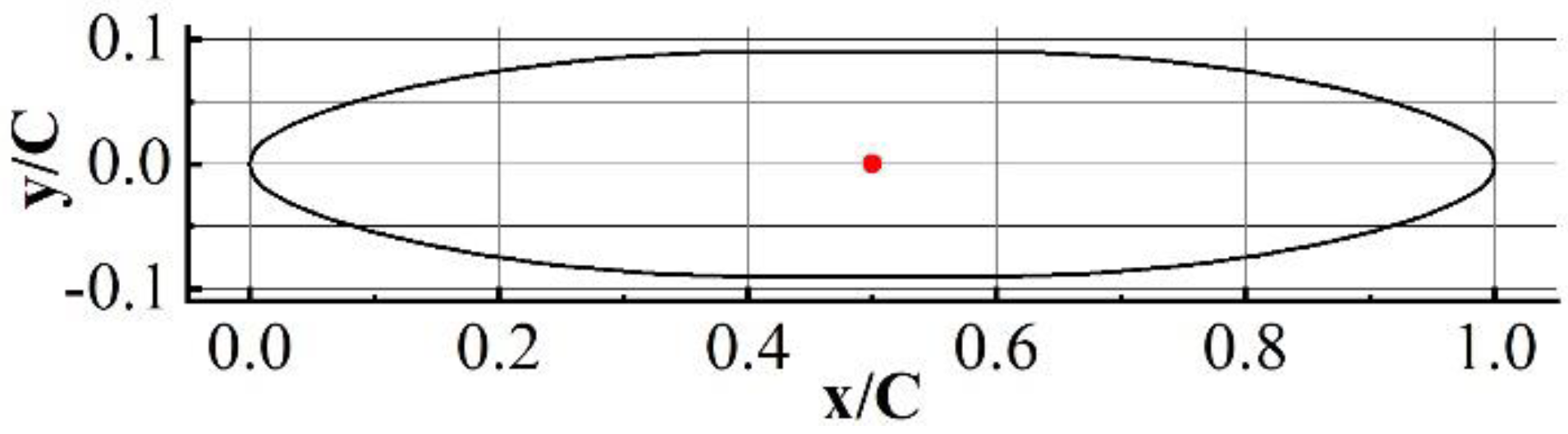
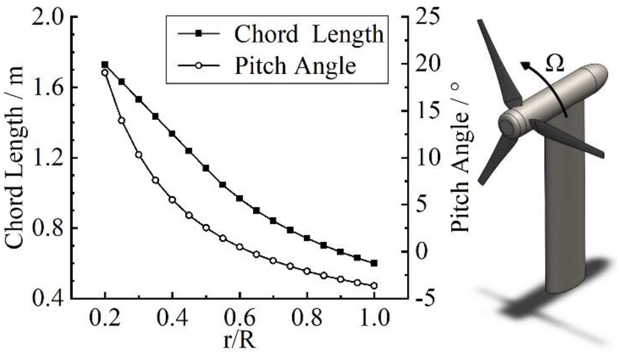
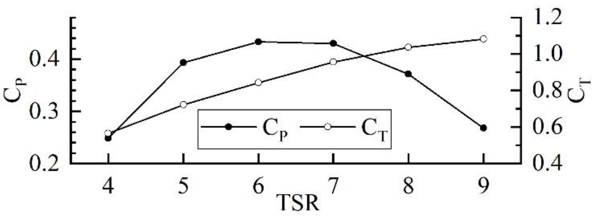
2.1. Baseline BHATT Design

To make the BHATT work equally efficiently in both ebb and flood tides without additional moving parts, the hydrofoil should be centrosymmetric. Referring to the designs of Shiu et al. [12], Nedyalkov [26], and Guo et al. [13], a bidirectional hydrofoil based on NACA 65-018 was designed. No-dimensional geometry of the bidirectional hydrofoil is shown in Figure 1.
An 18 m diameter BHATT with three straight blades was designed as the baseline turbine. The design is based on Schmitz Method [27], which is recommended by El-Okda [28], and also used by Qblade [29]. The turbine blade uses the bidirectional hydrofoil mentioned above as cross sections. The axis of twist of each section is 0.5C away from the leading edge. The design rotational speed, Ω, is 1.6 rad/s with a TSR of 6. TSR is defined as follows:
TSR = R · Ω   U
The size of the nacelle and support structure were referred to Atlantic AR1500 tidal turbine [3]. The hub and the nacelle have a diameter of 2.4 m and a total length of 12.3 m. An elliptic mono-pile support with a major axis of 4.32 m (0.24D) and a minor axis (width) of 2.16 m (0.12D) was chosen as the support structure. The centerline of the rotor is 18 m away from the seabed. The distance between the rotor plane and the leading edge of the support is 3.24 m (0.18D). More details about the blades and BHATT are shown in Figure 2.

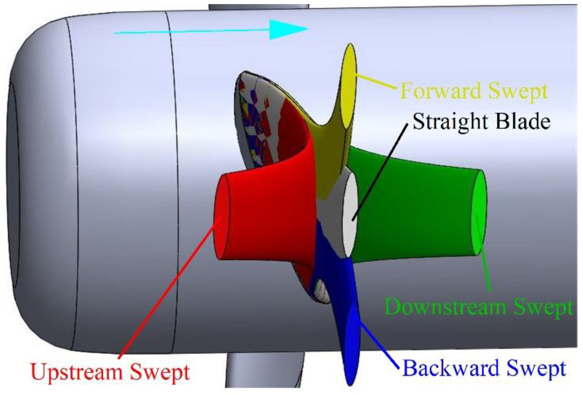
2.2. Swept Blades Design

Four kinds of swept blades are taken into consideration as follows:
(1)
Sweep toward the direction of the blade rotation (forward swept);
(2)
Sweep toward the opposite direction of the blade rotation (backward swept);
(3)
Sweep toward the upstream direction (upstream swept);
(4)
Sweep toward the downstream direction (downstream swept).
The straight blade and four directions of swept blades are shown in Figure 3.
It should be noted that the chord length, the pitch angle, and the radial location of blade sections stay unchanged when the blade sweeps. The only thing that changes is the distance between the center point of the blade section and the pitch line of the blade. The patch line overlaps the centerline of the straight blade.
The distance between the center point of the blade section and the pitch line is defined as:
d l = { d tip ( r     r ss R     r ss ) z                   r   r ss                     0                                             r < r ss
The equation is referred to STAR [30]. The dl is the distance between the center point of the blade section and the pitch line of the blade. The dtip is the dl of the blade tip section, in other word, the tip offset. The default dtip is 0.1R. The rss is the radial location of the sweep start section with the default value of 0.3R. The z is 3.656 by default according to Khalafallah et al. [19].

3. Numerical Modeling

3.1. Numerical Framework
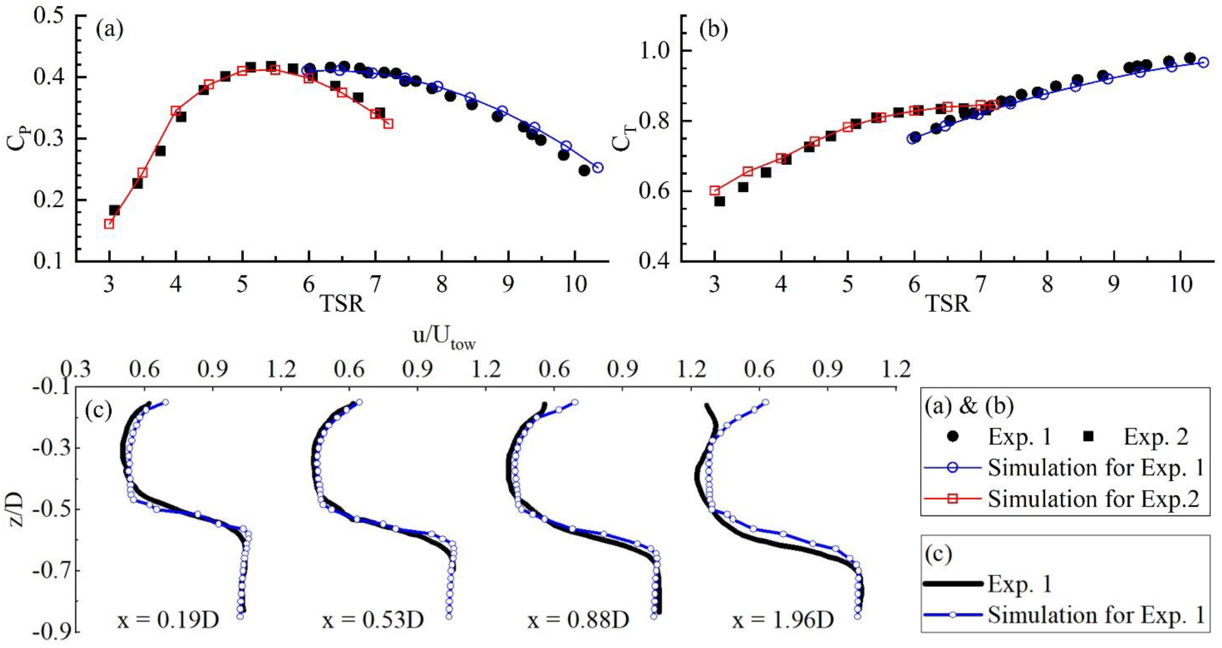
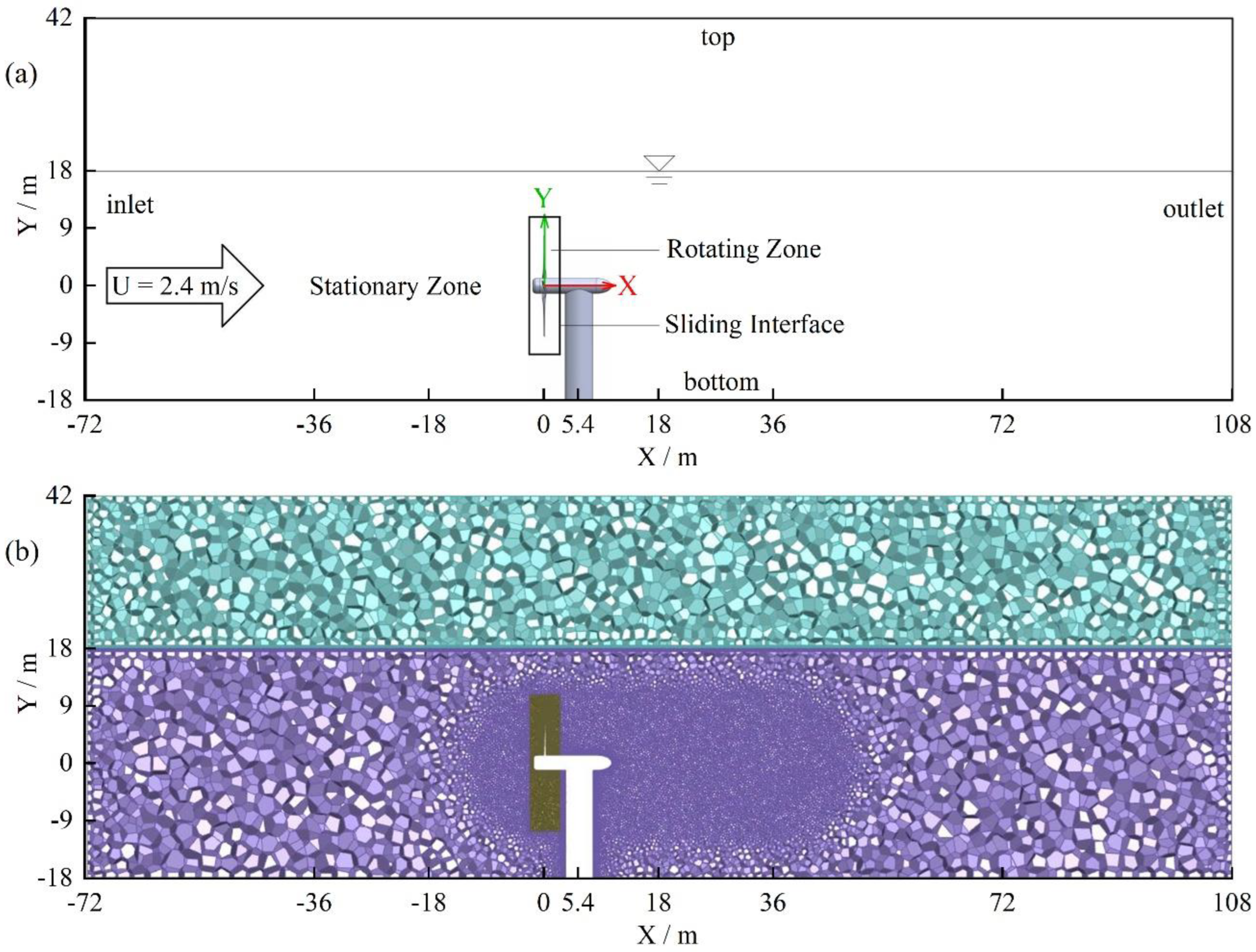
A finite-volume VOF-based (volume of fluid) solver interDyMFoam (a part of opensource code OpenFOAM 4.1) is adopted to solve the incompressible Navier-Stokes equations. It can simulate HATTs precisely [31,32] with a sliding mesh method that has been proven to produce good results [33]. According to Wang et al. [34], a k-ω SST model is used to describe the turbulence, as it can balance the accuracy, the computational resource cost, and stabilization of the simulation. To reduce the cost of computational resource without any loss of accuracy, a high-quality polyhedral mesh [35,36,37] generated through TGrid 18.1 is used to describe the geometry of the computational domain. The numerical schemes can be seen in ref. [38].
To validate the numerical framework, the experiments by Lust et al. [39,40] (Exp. 1) and the experiments by Guo et al. [13] (Exp. 2) were adopted. Among these, Lust et al. chose NACA 63-618 hydrofoil, and present the performance [38] and the near-wake flow fields [40] of their HATT; whereas Guo et al. [13] adopted bidirectional hydrofoils, but only presented the performance of their BHATT. It should be noted that the interDyMFoam solver was used for Exp. 1, while the pimpleDyMFoam solver, regarded as a version of the interDyMFoam without VOF model [41], was used for Exp. 2. It is because there was no free surface in the cavitation tunnel for Exp. 2. The depth and width of computational domains are equal to the sizes of experiment facilities, and the length is 3D upstream and 6D downstream.
The results, shown in Figure 4, indicate that the CP and CT predicted by the numerical model agree well with the measurements in Exp. 1 and 2, with non-dimensional numbers CP and CT being defined as:
C P = T Ω 0.5 ρ π R 2 U 3
C T = F ax 0.5 ρ π R 2 U 2
The T (torque of the rotor) and the Fax (axial thrust on the rotor) are gathered by the OpenFOAM built-in function “forces”, and then averaged over three rotational cycles of the HATT. The density of water ρ is 998.2 kg/m3 for validations, and 1024.53 kg/m3 for the full-scale simulation, respectively. The kinematic viscosity of water is 1.006 × 10⁻⁶ m2/s for validations, and 1.048 × 10⁻⁶ m2/s kg/m3 for the full-scale simulation, respectively. The kinematic viscosity of air is 1.8 × 10⁻⁵ m2/s for validations, and 1.513 × 10⁻⁵ m2/s kg/m3 for the full-scale simulation, respectively.

3.2. Model Setup

A cuboid with a length of 180 m (4D upstream + 6D downstream), a width of 72 m (3D + 3D), and a height of 60 m is set as the computational domain for the full-size simulation. Herein, the water depth is maintained at 36 m (2D). As shown in Figure 5a, the computational domain is divided in two zones by the sliding interface. The boundary conditions used in the simulation for Exp. 1 are adopted in the full-scale simulations. The inlet has a uniform velocity of 2.4 m/s with a turbulence intensity of 5%. An outlet phase mean velocity boundary condition is used for the outlet to keep the water level without disturbing the flow fields [42]. The velocity on the top will be calculated from the pressure gradient near the top, in which total pressure is set to 0. The bottom and side walls are set as symmetry boundaries. All parts of the BHATT are simplified as a smooth wall.
This simulation employs a Cartesian coordinate system with the origin located at the intersection point of three centerlines of blades, as shown in Figure 5a. The positive X-axis is in the streamwise direction, and parallel to the centerline of the rotor. The positive Y-axis is in the opposite direction of gravity, and the positive Z-axis is outside the paper in Figure 5a. Therefore, the direction of rotation is (−1 0 0) according to right-hand rule.
The cell-related lengths employed in the full-scale simulation are similar to the simulations for Exp. 1 and 2. To test the mesh convergence, three sets of rotor mesh named as mesh 1 (0.71 × 10⁶ cells), mesh 2 (0.99 × 10⁶ cells), and mesh 3 (1.37 × 10⁶ cells) were compared. Taking TSR = 6 as instant, The CP of the three sets is 0.401, 0.427, and 0.436, respectively, while the CT of three sets is 0.852, 0.851, and 0.846, respectively. According to the definition of NACA [43], the GCI23 (Grid Convergence Index of mesh 2 and mesh 3) for CP is 0.0135, and the GCI23 for CT is 0.0085. Therefore, the set of mesh 3 was adopted, and the rotor mesh size sets for different surfaces and zones stay unchanged for following simulations. The mesh for whole computational domain is shown in Figure 5b. The total number of cells in rotating and stationary zone is a little more than 2.0 × 10⁶. The y+ of the whole turbine ranges from 20 to 300 in most cases. However, only very small surface has a y+ less than 30, and the y+ of the leading edge is always more than 30.
The performance of the BHATT with straight blades is shown in Figure 6. The CP and CT of the BHATT with straight blades is set as CPref (reference CP) and CTref (reference CT), respectively.

4. Results and Discussion

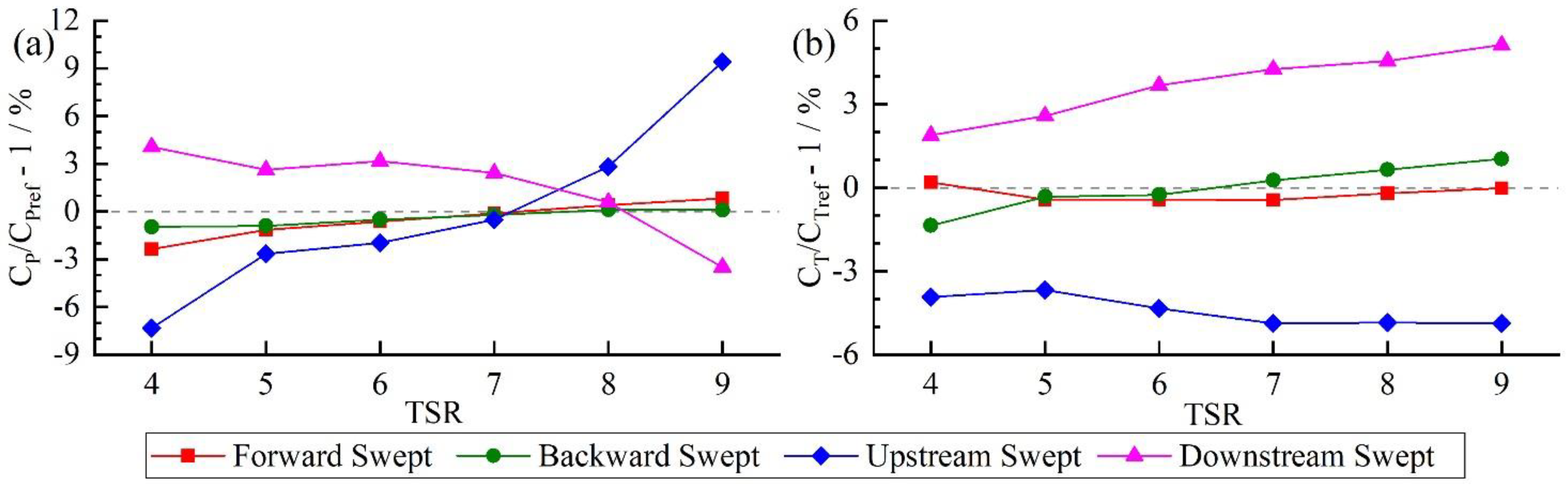
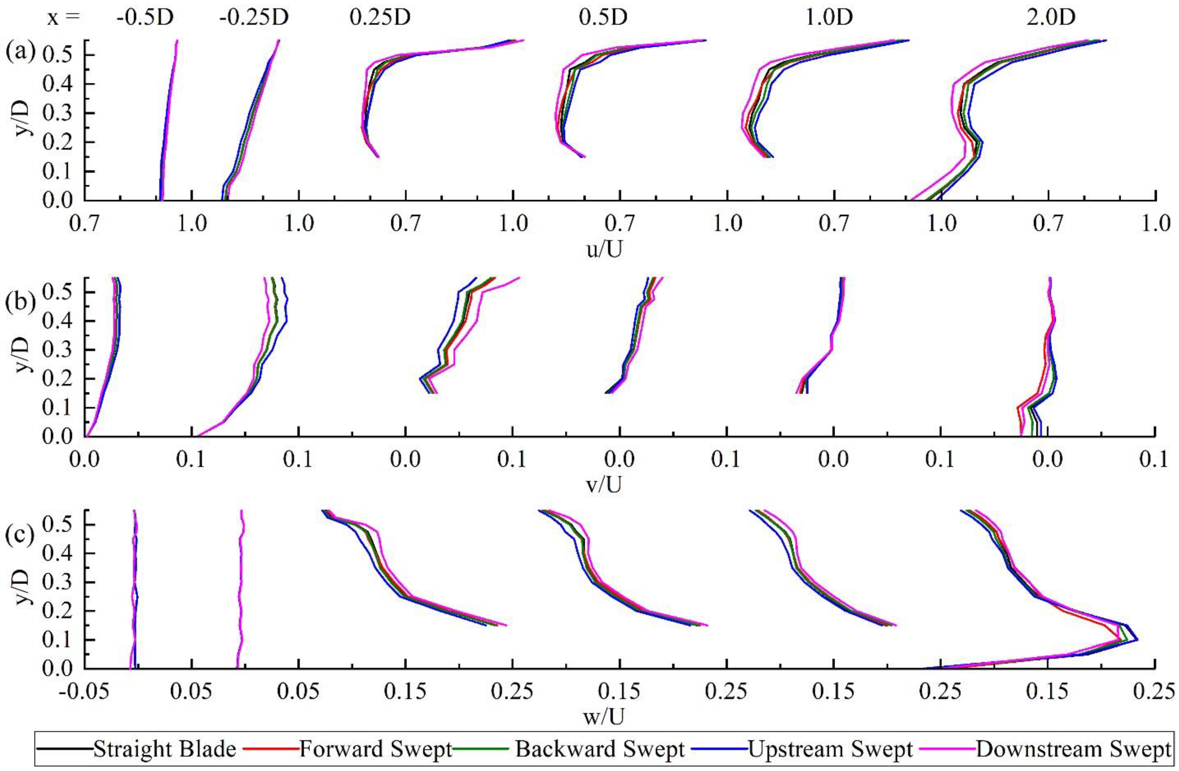
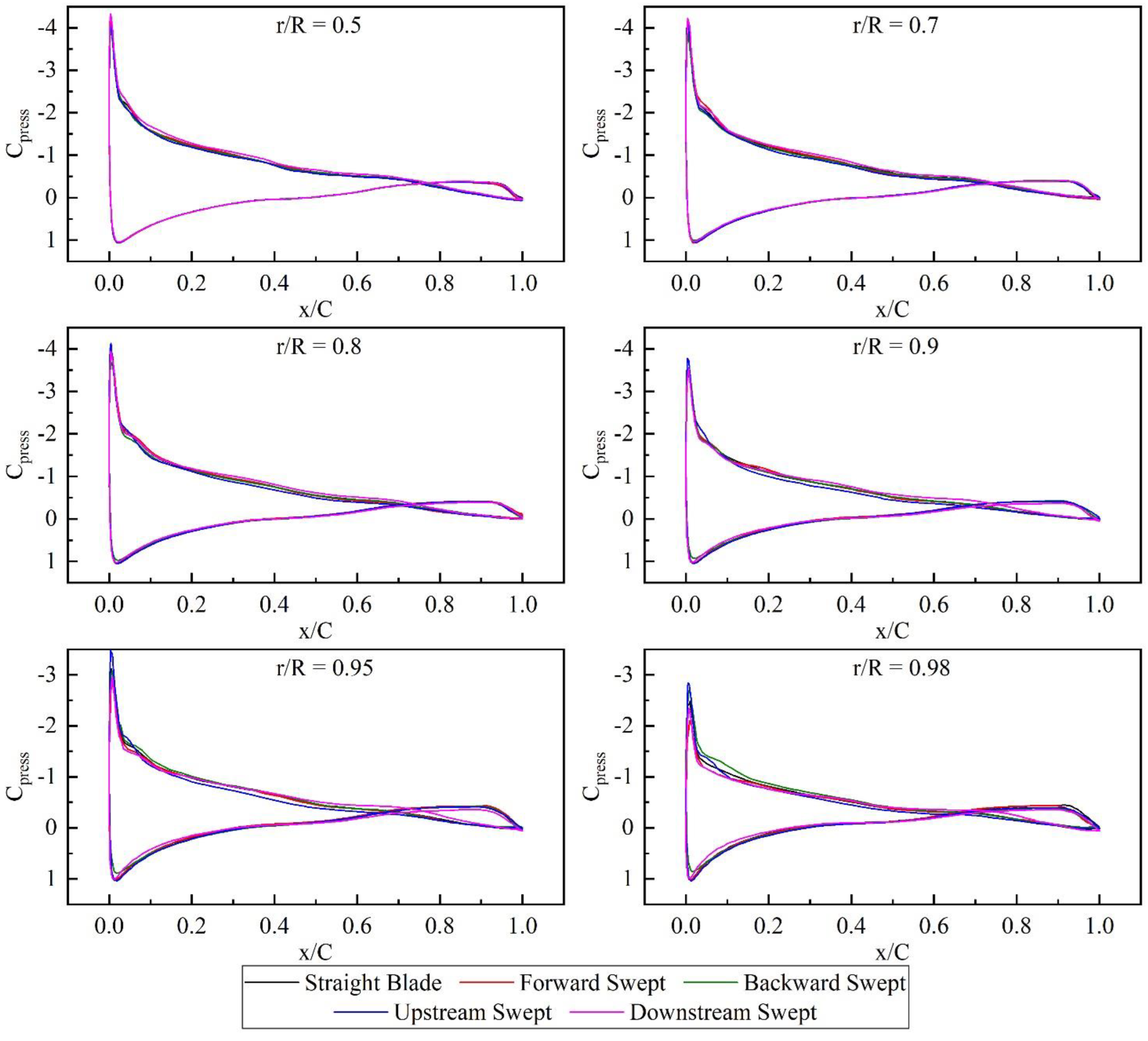
4.1. Influence of Swept Blades in Different Directions

Figure 7 demonstrates the variation in the performance of the BHATT due to the swept blades. It can be seen that the forward swept blade and the backward swept blade have a slight effect in the similar manner on the CP and CT of the BHATT. At design TSR, the forward swept blade causes a 0.6% decrease in the power with a 0. 4% decrease in the thrust, while the backward swept blade reduces the power by 0.5% and the thrust by 0.3%. At TSR = 9, the forward swept blade gives rise to a 0.8% increase in the power, while the value of the backward swept blade is just 0.1%. Meanwhile, the thrust on the rotor changes by −0.03% and 1.0% because of the forward and backward swept blades, respectively. To summarize, there is not attractive enough effect, neither on enhancing the power, nor on reducing the thrust, to adopt the forward or backward swept blades in the BHATT.
On the contrary, the upstream and downstream swept blades have a remarkable impact on the power and thrust of the BHATT. Unlike the forward and backward swept blades, the influence of the upstream and downstream swept blades on the power of the BHATT is segmented. That is, at TSR ≤ 7 and TSR > 8, they exert an influence upon the power in an opposite manner. Concretely speaking, the upstream swept blade leads to a 2.0% decrease in the power with a 4.3% decrease in the thrust at TSR = 6. At TSR = 9, The upstream swept blade improves the power by up to 9.4% with a decrease in the thrust by 4.9%. Differ to the upstream swept blade, the downstream swept blade contributes to a 3.2% increase in the power with a 3.7% increase in the thrust at TSR = 6. At TSR = 9, the downstream swept blade reduces the power by 3.5% with a 5.1% growth in the thrust. Given that the rotor should be maintained at TSR = 6 to extract the maximum amount of energy, the upstream swept blade can be regarded as a good method to reduce the load on the blade, whereas the downstream swept blade is considered to be a practical method to increase the power. Moreover, assuming that the flood and ebb tidal stream is symmetrical, the downstream swept blade make the BHATT extract 0.6% more energy over one day. Besides, in asymmetrical tidal stream, the BHATT with downstream swept blades for stream with higher velocity can generate more than 0.6% energy over one day.
As aforementioned, the influence of swept blades on the power at TSR = 6 is opposite from that at TSR = 9. Therefore, the influence of swept blades at TSR = 6 and TSR = 9 will be analyzed separately.
Research on the flow velocity distributions near the rotor, especially the flow velocity distributions in the wake is important [44,45]. The flow velocity distributions near the rotor at TSR = 6 are represented in Figure 8. In front of the rotor, there is almost no difference in the velocity distribution between the straight blades, the forward swept blade, and the backward swept blades. Meanwhile, compared with the straight blade, the upstream swept blade leads to a lower axial flow velocity and a higher spanwise flow velocity at x/D = −0.25, whereas the downstream swept blade performs just the opposite behavior, i.e., a high axial speed and a low spanwise speed. Moreover, the circumferential flow velocity is not affected by the blade sweep. In the wake from the rotor, in comparison with the straight blade, there is a higher axial flow velocity and a lower spanwise flow velocity from the upstream swept blade, while there exist a lower axial flow velocity and a higher spanwise flow velocity from the downstream swept blade. In addition, there is a slight difference in the flow velocity distribution between the straight blade, the forward swept blade, and backward swept blade. Furthermore, the effect of swept blades on the circumferential flow velocity shares the same tendency with that on the spanwise flow velocity, and both attenuate with the increase of the distance from the rotor. It is noted that the difference in the spanwise and circumferential flow velocity at x/D = 2.0 can be ascribed to the shedding vortices from the nacelle.
Although the swept blades have the opposite effect on the power of the BHATT at TSR = 6 from that at TSR = 9, the variation in the velocity of the incoming flow due to the blade sweep at TSR = 9 shares the same trend with that at TSR = 6, as shown in Figure 9. Behind the rotor, the effect of the swept blades on the axial flow velocity at two TSRs also share the same trend, even though the tendency of the axial flow velocity distribution along the Y-axis sharply deviates. In addition, all types of swept blades have a slight effect on the spanwise flow velocity in the wake. Moreover, the effect of the upstream and downstream swept on the circumferential flow velocity changes with the increase of the distance from the rotor, while the effect of the forward and backward swept blades is negligible.
The surface streamlines above the blades at TSR = 6 are demonstrated in Figure 10, and those at TSR = 9 are shown in Figure 11. There is not much meaningful difference observed at r/R ≤ 0.8 above the suction surfaces due to the strong spanwise flow and separated flow. However, it can be seen that the directions of the separated flow near the trailing edge changes remarkably above the suction surfaces due to the introduction of the forward and backward swept blades. The similar phenomenon can also be observed above the suction surfaces at TSR = 9, as represented in Figure 11. Above the pressure surface, the upstream swept and downstream swept blades have a negligible impact on the flow field at both TSR = 6 and 9. On the contrary, the forward and backward swept blades do change the directions of the local stream observably at r/R > 0.8. That is to say, the streamlines above the pressure surfaces of the forward and backward swept blades at r/R > 0.8 are not parallel to the blade sections as that of the straight blade.
Tip vortices generated by blades sweeping in different directions at TSR = 6 and 9 in the wake are illustrated in Figure 12. Herein, the region exhibited above is 0.06 m (0.1 CTip) away from the trailing edges of blades, and only involving the vortices in the same directions as the theoretical tip vortex. It is clear that the shape of tip vortices is similar at TSR = 6 and 9, while swept blades in different directions lead to tip vortices formed in diverse shapes. It should be noted that there are two vortex cores of the tip vortex from the forward swept blade, which are for two tip vortices from the forward swept tip. One is the flow from the leading edge of the blade to the suction surface, and the other is the flow from the pressure surface to the suction surface. In other words, a new vortex generated from the projecting leading edge of the blade tip. Except for the forward swept blade, the other swept blades have a slight impact on the peak vorticity of the tip vortices at TSR = 6. While at TSR = 9, the backward swept blade causes a remarkable increase in the peak vorticity, while the upstream swept blade observably reduces the peak vorticity.
Besides the flow field surrounding the blades, the pressure distributions on the blades are also analyzed. The pressure coefficient distributions on six sections of diverse blades at TSR = 6 are shown in Figure 13, with the Cpress being defined as:
C press = p _ rgh p _ rgh ref 0.5 ρ ( ( C Pref C Tref U ) 2 + ( Ω r ) 2 )
The p_rgh can be regarded as a physical quantity to describe pressure without hydrostatic pressure. It is also widely used in multi-phases flow solvers of OpenFOAM to replace pressure in order to improve convergence. The p_rgh of 181,115.5 N/m2 at the point (−54 0 0) is chosen as the p_rghref. The (CPref/CTref)U in Equation (5) is the reference theoretical averaged flow speed through the rotor plane according to the Schmitz Method [27].
At r/R ≤ 0.7, except for a slightly greater negative pressure on the leading edge and the middle part of the suction pressure of the downstream swept blade, other swept blades have a negligible impact on the pressure distributions. At r/R ranging from 0.8 to 0.9, a higher negative pressure on the leading edge and a lower negative pressure on the middle part of the suction surface are observed above the upstream swept blade, while there is a greater negative pressure on the leading edge and the middle part of the suction surface above the downstream swept blade. In general, the difference between the straight blade and other swept blades in the pressure distribution is quite tiny. At r/R = 0.95 and 0.98, a significant variation occurs because of the blade sweep. More specifically, the forward swept blade leads to a lower negative pressure on the leading edge of the suction surface, while the backward swept blade results in an increase in the negative pressure on the leading edges of the suction surface and a decrease in the positive pressure on the leading edges of the pressure surface. Meanwhile, the upstream swept blade brings a larger effect with the same tendency as that at r/R ranging from 0.8 to 0.9, and the downstream swept blade leads to a lower negative pressure on the leading edge of the suction surface and a lower positive on the leading edge of the pressure surface.
The pressure distributions on various sections at TSR = 9 are presented in Figure 14. It can be seen that the blade sweep do not affect the pressure distribution at the section at r/R = 0.5. At r/R ranging from 0.7 to 0.98, there are a higher negative pressure on the middle part of the suction surface of the downstream swept blade, and a lower negative pressure on that of the upstream swept blade. Meanwhile, little difference in the pressure distribution is observed on the forward and backward swept blade. Except for the variation in the pressure distributions on the middle part of the suction surfaces, at r/R ranging from 0.9 to 0.98, the upstream swept blade enhances negative pressure on the leading edge of the suction surface, while the downstream swept blade brings a lower negative pressure on the leading edge of the suction surface and a lower positive pressure on that of the pressure surface. It should be also noted that the difference in the pressure on the trailing edge between the suction and pressure surfaces of the downstream swept blade decreases observably. Moreover, the forward swept blade leads to a lower negative pressure on the leading edge of the suction surface at r/R = 0.98, while backward swept blade brings the opposite effect.

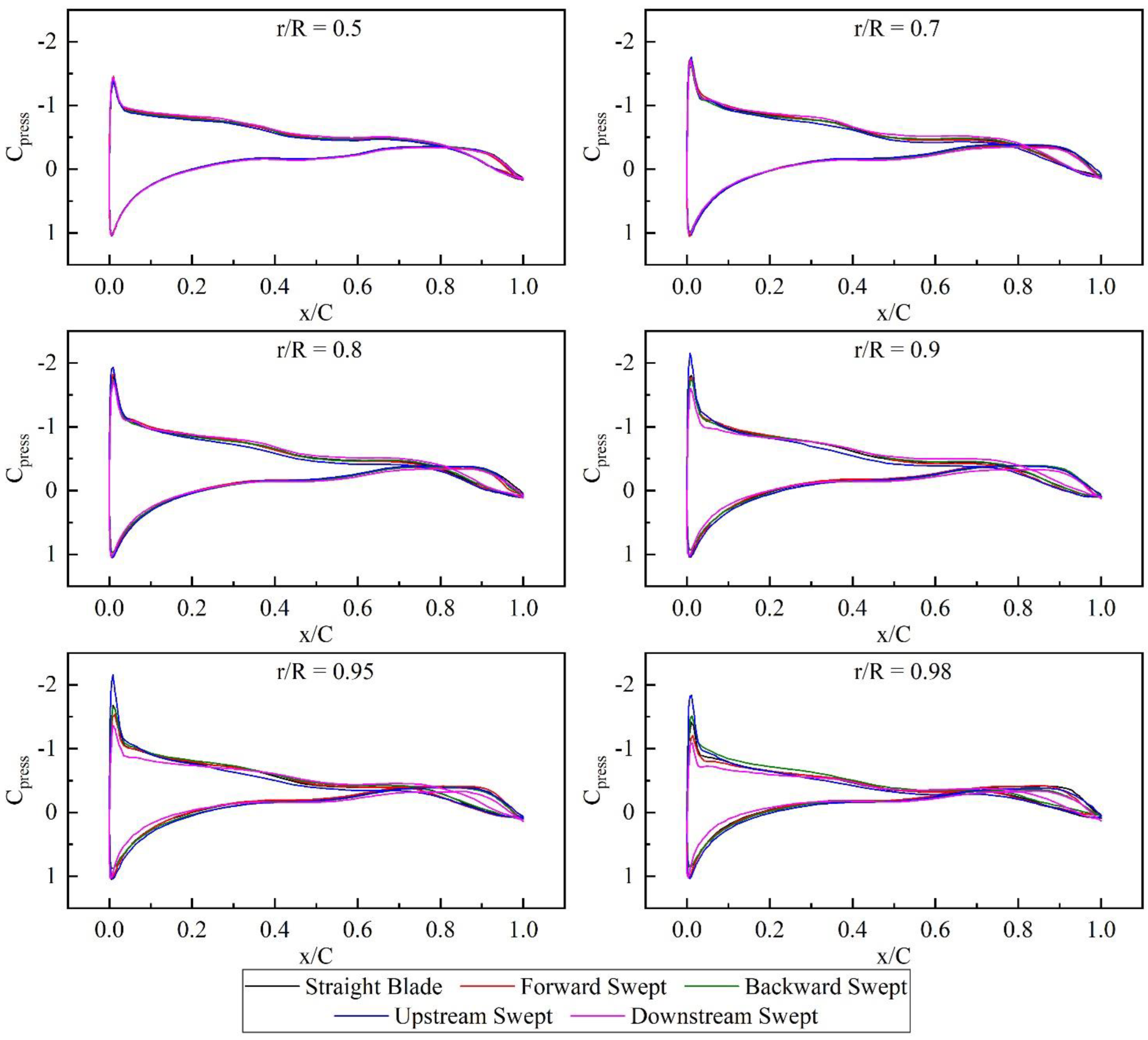
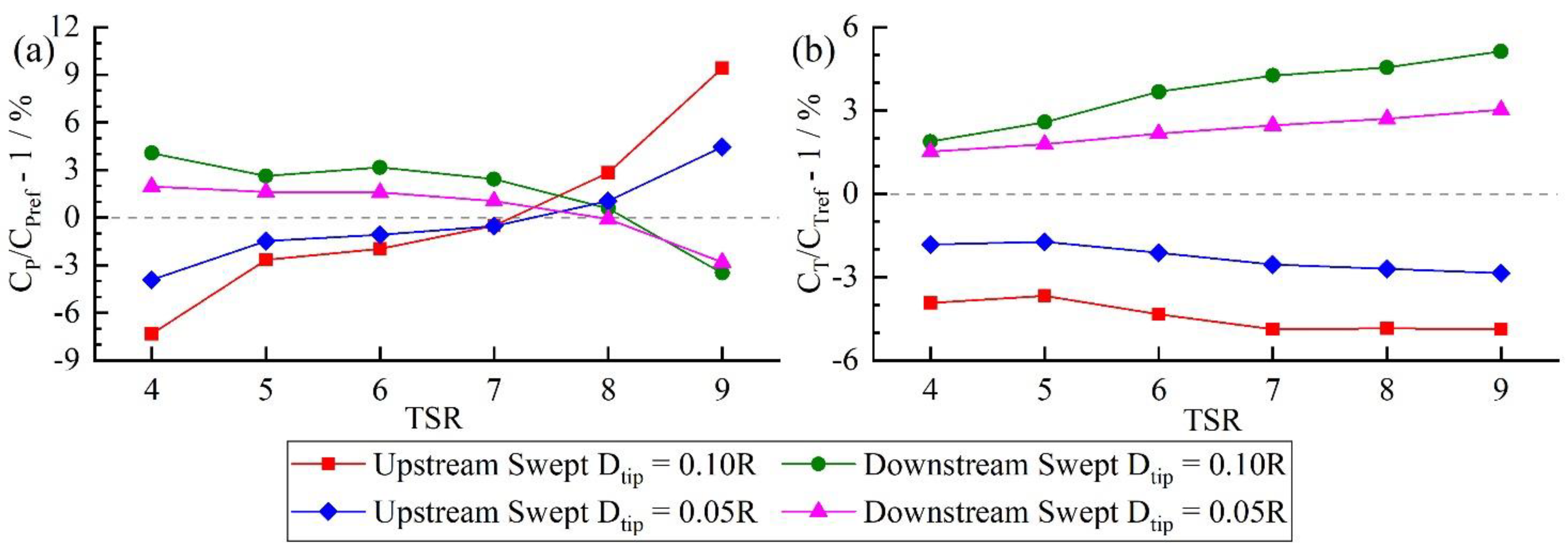
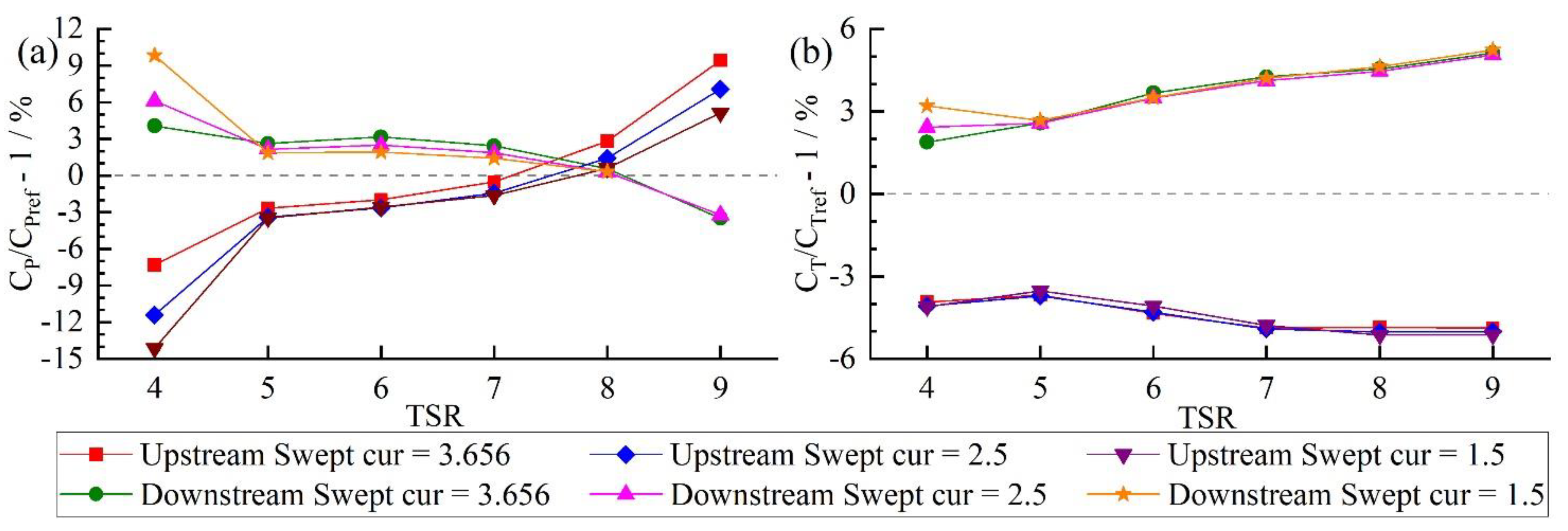
4.2. Influence of Swept Blades with Different Parameters

Apart from the direction that the blade sweeps in, the effect of tip offset (dtip in Equation (5)) and the curve exponent (z in Equation (5)) on the performance of the BHATT are also analyzed. Due to the slight effect of the forward and backward swept blade, only the upstream and downstream swept blades are taken into consideration.
The variation in the power and thrust versus diverse swept blades with different dtip is demonstrated in Figure 15. It is clear that the swept blades with different dtip in the same directions have the same trend in the effect on the power and thrust of the BHATT. Moreover, the larger the tip offset, the greater the effect on both the power and the thrust.
Figure 16 illustrates the variation of the power and the thrust of the BHATT with diverse curve exponents. It is clear that the curve exponent has a limited effect on the power, while the thrust is affected in a slight manner except for the thrust at TSR = 4. To be specifical, at TSR ≥ 8, the larger the curve exponent for the upstream swept blade, the greater the effect on the power. On the contrary, at TSR ≤ 7, the smaller the curve exponent for the upstream swept blade, the greater the effect on the power. It is noted that the upstream swept blade with larger curve exponent can always produce more power than that with smaller curve exponent. Moreover, the smaller curve exponent for the downstream swept blade causes a greater effect on the power at TSR = 4. Furthermore, the power is affected more remarkably owing to the larger curve exponent for the downstream swept blade at TSR ranging from 5 to 8, and the power of the rotor with the downstream swept blade keeps almost unchanged at TSR = 9.

4.3. Potential Reasons for the Variation in the Power and the Thrust

Some researchers think that the radial (spanwise) force variation may result in the power variation [19,20]. More specifically, the lower positive radial force or the higher negative radial force expend the stream tube through the rotor [46]. In other words, the axial flow velocity through the rotor becomes larger. Larger velocity means more energy inputting, leading to an increase in the power of the rotor.
However, there are two doubts about this opinion. Primarily, the negative radial force on the blade refers to a positive radial force from the blade on the flow. This will contribute to a larger spanwise flow velocity in front of the rotor and resultantly a lower axial flow velocity through the rotor. The radial force driven by a single blade on the flow is shown in Figure 17, with the non-dimensional number CRF being defined:
C RF = F r a 0.5 ρ π R 2 U 2
Herein, Fra present the radial force on a single blade. It can be seen that the upstream swept blade exerts a lower positive radial force on the flow, while the downstream swept blade applies a higher positive on the flow compared with the straight blade. However, as mentioned in Section 4.1, a lower axial flow velocity is expected to be resulted from the upstream swept blade, whereas the downstream swept blade is considered to create a higher velocity. This clearly contradicts the aforementioned hypothesis.
Besides, the fact that the larger speed of the incoming axial flow velocity does not necessarily result in higher power output, becomes the secondary question. That is to say, the axial velocity is not always positively correlated with the power. For instance, there is a lower axial flow velocity occurring in front of the rotor with the upstream swept blade at both TSR = 6 and 9, however, the upstream swept blades have the opposite effect on the power output of the BHATT at TSR = 6 and 9. More specially, the upstream swept blades generate less power at TSR = 6, whereas generate more power at TSR = 9 compared with the straight blades. In other words, the similar variation in the axial flow velocity results in the opposite variation in the power. As a result, the variation in the power and thrust cannot be ascribed solely to the change in the radial force.
As shown in Figure 8 and Figure 9, the blade sweep in different directions leads to the difference in the incoming flow, resulting in the changes in the inputting power. Afterward, as demonstrated in 10 and 11, the flow surrounding the blade changes due to the blade sweep, to which the variation in the pressure on the blades shown in Figure 13 and Figure 14 can be attributed. Moreover, the difference in the tip vortex can also partially account for the variation in the power and thrust. In a word, the variation in the performance of the BHATT can be ascribed to complex flow field changes as the result of the blade sweep. However, the more specifical relation between the swept blades and the flow field changes needs further research.

5. Conclusions

This study developed a 3D numerical model based on interDyMFoam, accompanied by the k-ω SST model, VOF model, and the sliding mesh method to numerically investigate the influence of blade sweep on the full-scale BHATT. After the validation of the numerical framework and the test of mesh convergence, the influence of swept blades in different directions on the power and thrust of the rotor and the flow field surrounding the rotor are analyzed. Afterward, the influence of tip offset and the curve exponent for the blade sweep are taken into consideration. Finally, the possible reason that could contribute to the variation in the power and thrust is discussed.
The swept blades implement the effect on the power in an inconsistent behavior when TSR ≤ 7 and >8. The forward and backward swept blades have a slight effect on the power and thrust of the BHATT, coupled with a slight influence on the incoming flow and the wake from the rotor. Moreover, they have a remarkable impact on the pressure distribution on the sections at TSR > 0.95. This phenomenon can be partially ascribed to the considerable variation in the tip vortex owing to the blade sweep.
Besides, the upstream swept blade contributes to a 4.3% decrease in the thrust with a 2.0% reduction in the power at design TSR, while the downstream swept blade brings a 3.2% improvement in the power with a 3.7% growth in the thrust. That is to say, assuming that the flood and ebb tidal stream are symmetrical and the BHATT operates at design TSR, the downstream swept blade make the BHATT extract 0.6% more energy over one day. Besides, in asymmetrical tidal stream, the BHATT with downstream swept blades for stream with higher velocity can generate more than 0.6% energy over one day. Noted that, the effect of the upstream and downstream swept blades at TSR = 9 is more considerable than that at design TSR. Meanwhile, the influence of upstream and downstream swept blades on the incoming flow and the wake flow presents in contrary tendencies, and the effect on the pressure distribution at r/R > 0.5 becomes differ likewise.
The tip offset has a remarkable influence on the effect of the upstream and downstream swept blade on the performance of the BHATT. On the contrary, the curve exponent has a slight effect on the power of the rotor with upstream or downstream swept blade, and a negligible effect on the thrust of that.
The variation in the power and the thrust of the BHATT can be ascribed to several reasons, e.g., the changes in the incoming power, the changed flow field surrounding the blades, and the difference in the tip vortex. However, it needs further study to understand the more specifical relationship between the swept blades and the flow field changes.

Author Contributions

S.L.: conceptualization, methodology, software, validation, formal analysis, investigation, writing—original draft. J.Z.: writing—review and editing, supervision, resources, project administration. K.S.: writing—original draft, writing—review and editing. Y.G.: writing—review and editing, supervision. D.G.: writing—review and editing. All authors have read and agreed to the published version of the manuscript.

Funding

This work was supported by the Postgraduate Research & Practice Innovation Program of Jiangsu Province (SJKY19_0502) and the Fundamental Research Funds for the Central Universities (2019B61214).

Institutional Review Board Statement

Not applicable.

Informed Consent Statement

Not applicable.

Data Availability Statement

Not applicable.

Conflicts of Interest

The authors declare no conflict of interest.

Nomenclature

AAera of the rotor [m2]
CChord length [m]
CTipTip chord length [m]
CPPower coefficient [-]
CTThrust coefficient [-]
CRFRadial force coefficient [-]
CPrefReference CP [-]
CTrefReference CT [-]
CpressPressure coefficient [-]
DDiameter of rotor [m]
dtipDistance between center point of blade tip section and pitch line [m]
dlDistance between center point of local blade section and pitch line [m]
FaxAxial thrust on rotor [N]
FraRadial force on one blade [N]
p_rghPressure without hydrostatic pressure [N/m2]
p_rghrefReference p_rgh [N/m2]
RRadius of rotor [m]
rRadius of local blade section [m]
rssRadius of sweep start section [m]
TTorque on rotor [N·m]
TSRTip speed ratio [-]
UIncoming flow velocity [m/s]
zCurve exponent [-]
ρDensity of water [kg/m3]
ΩRotational speed [rad/s]

References

  1. British Petroleum. Statistical Review of World Energy 2020. 2021. Available online: https://www.bp.com/content/dam/bp/business-sites/en/global/corporate/pdfs/energy-economics/statistical-review/bp-stats-review-2020-full-report.pdf (accessed on 10 October 2021).
  2. Rourke, F.O.; Boyle, F.; Reynolds, A. Tidal energy update 2009. Appl. Energy 2010, 87, 398–409. [Google Scholar] [CrossRef]
  3. Atlantic Resource. AR1500 Tidal Turbine. 2016. Available online: https://simecatlantis.com/wp-content/uploads/2016/08/AR1500-Brochure-Final-1.pdf (accessed on 29 December 2021).
  4. Nachtane, M.; Tarfaoui, M.; Goda, I.; Rouway, M. A review on the technologies, design considerations and numerical models of tidal current turbines. Renew. Energy 2020, 157, 1274–1288. [Google Scholar] [CrossRef]
  5. Zhou, Z.; Scuiller, F.; Charpentier, J.F.; Benbouzid, M.; Tang, T. An up-to-date review of large marine tidal current turbine technologies. In Proceedings of the 2014 International Power Electronics and Application Conference and Exposition, Shanghai, China, 5–8 November 2014; pp. 480–484. [Google Scholar]
  6. Nielsen, N.M. Inquiry into the Development of a Non-Fossil Fuel Energy Industry in Australia: Case Study into Selected Renewable Energy Sectors. Available online: https://www.aph.gov.au/Parliamentary_Business/Committees/House_of_Representatives_Committees?url=isr/renewables/submissions/sub121pdf (accessed on 25 October 2021).
  7. Allo, J.; Dhome, D.; Battaglia, B. Feedbacks from Sabella D10 1 MW Sea Trials. Available online: https://docplayer.net/44482787-Feedbacks-from-sabella-d10-1-mw-sea-trials.html (accessed on 15 December 2021).
  8. DTI. Economic Viability of Simple Tidal Stream Energy Capture Device. 2007. DTI Project No: TP/3/ERG/6/1/15527/REP, URN 07/575. Available online: https://www.scribd.com/document/318517017/Economic-Viability-of-Simple-Tidal-Stream-Energy-pdf (accessed on 12 February 2022).
  9. Liu, P.; Veitch, B. Design and optimization for strength and integrity of tidal turbine rotor blades. Energy 2012, 46, 393–404. [Google Scholar] [CrossRef]
  10. Liu, P.; Bose, N. Prototyping a series of bi-directional horizontal axis tidal turbines for optimum energy conversion. Appl. Energy 2012, 99, 50–66. [Google Scholar] [CrossRef]
  11. Liu, P.; Bose, N.; Frost, R.; Macfarlane, G.; Lilienthal, T.; Penesis, I.; Windsor, F.; Thomas, G. Model testing of a series of bi-directional tidal turbine rotors. Energy 2014, 67, 397–410. [Google Scholar] [CrossRef]
  12. Shiu, H.; van Dam, C.P. Active Flow Control on Bidirectional Rotors for Tidal MHK Applications. 2013; University of California, Davis. DOE Award Number: DE-EE0004568. Available online: https://tethys-engineering.pnnl.gov/publications/active-flow-control-bidirectional-rotors-tidal-mhk-applications (accessed on 25 October 2021).
  13. Guo, B.; Wang, D.; Zhou, X.; Shi, W.; Jing, F. Performance Evaluation of a Tidal Current Turbine with Bidirectional Symmetrical Foils. Water-Sui. 2020, 12, 22. [Google Scholar] [CrossRef] [Green Version]
  14. Ashwill, T.; Kanaby, G.; Jackson, K.; Zuteck, M. Development of the Swept Twist Adaptive Rotor (STAR) Blade. In Proceedings of the 48th AIAA Aerospace Sciences Meeting, Orlando, FL, USA, 4–7 January 2010. [Google Scholar]
  15. Amano, R.; Avdeev, I.; Malloy, R.; Shams, M.Z. Power, structural and noise performance tests on different wind turbine rotor blade designs. Int. J. Sustain. Energy 2013, 32, 78–95. [Google Scholar] [CrossRef]
  16. Larwood, S.; van Dam, C.P.; Schow, D. Design studies of swept wind turbine blades. Renew. Energy 2014, 71, 563–571. [Google Scholar] [CrossRef] [Green Version]
  17. Ding, Y.; Zhang, X. An optimal design method of swept blades for HAWTs. J. Renew. Sustain. Energy 2016, 8, 043303. [Google Scholar] [CrossRef]
  18. Shen, X.; Yang, H.; Chen, J.; Zhu, X.; Du, Z. Aerodynamic shape optimization of non-straight small wind turbine blades. Energy Convers. Manag. 2016, 119, 266–278. [Google Scholar] [CrossRef] [Green Version]
  19. Khalafallah, M.G.; Ahmed, A.M.; Emam, M.K. CFD study of some factors affecting performance of HAWT with swept blades. Int. J. Sustain. Energy 2017, 36, 489–501. [Google Scholar] [CrossRef]
  20. Kaya, M.N.; Kose, F.; Ingham, D.; Ma, L.; Pourkashanian, M. Aerodynamic performance of a horizontal axis wind turbine with forward and backward swept blades. J. Wind. Eng. Ind. Aerodyn. 2018, 176, 166–173. [Google Scholar] [CrossRef] [Green Version]
  21. Carriquiry, J.D.; Villaescusa, J.A.; Camacho-Ibar, V.; Walter Daesslé, L.; Castro-Castro, P.G. The effects of damming on the materials flux in the Colorado River delta. Environ. Earth Sci. 2011, 62, 1407–1418. [Google Scholar] [CrossRef]
  22. Sheng, L.; Zhou, Z.; Charpentier, J.F.; Benbouzid, M.E.H. Stand-alone island daily power management using a tidal turbine farm and an ocean compressed air energy storage system. Renew. Energy 2017, 103, 286–294. [Google Scholar] [CrossRef] [Green Version]
  23. Lewis, M.; Neill, S.P.; Robins, P.; Hashemi, M.R.; Ward, S. Characteristics of the velocity profile at tidal-stream energy sites. Renew. Energy 2017, 114, 258–272. [Google Scholar] [CrossRef]
  24. Atlantis. Available online: http://www.esru.strath.ac.uk/EandE/Web_sites/09-10/MCT/html/Home/atlantis.html (accessed on 22 December 2021).
  25. Smart Free Stream Turbine. Available online: https://www.smart-hydro.de/wp-content/uploads/2015/12/Datasheet_SMART_Freestream.pdf (accessed on 10 October 2021).
  26. Nedyalkov, I.P. Performance and Cavitation Characteristics of Bi-Directional Hydrofoils. Ph.D. Thesis, University of New Hampshire, Durham, NH, USA, 2018. [Google Scholar]
  27. Gasch, R.; Twele, J. Blade Geometry According to Betz and Schmitz; Springer: Berlin/Heidelberg, Germany, 2011; pp. 168–207. [Google Scholar]
  28. El-Okda, Y.M. Design methods of horizontal axis wind turbine rotor blades. Int. J. Ind. Elec. Drive 2015, 2, 135–150. [Google Scholar]
  29. Qblade. Available online: http://q-blade.org/project_images/files/guidelines_v06(1).pdf (accessed on 10 October 2021).
  30. Ashwill, T. Sweep-Twist Adaptive Rotor Blade: Final project report. Available online: https://www.osti.gov/biblio/973353-sweep-twist-adaptive-rotor-blade-final-project-report (accessed on 10 October 2021).
  31. Gebreslassie, M.G.; Tabor, G.R.; Belmont, M.R. Numerical simulation of a new type of cross flow tidal turbine using OpenFOAM—Part I: Calibration of energy extraction. Renew. Energy 2013, 50, 994–1004. [Google Scholar] [CrossRef]
  32. Nuernberg, M.; Tao, L. Three dimensional tidal turbine array simulations using OpenFOAM with dynamic mesh. Ocean Eng. 2018, 147, 629–646. [Google Scholar] [CrossRef] [Green Version]
  33. Liu, J.; Lin, H.; Purimitla, S.R. Wake field studies of tidal current turbines with different numerical methods. Ocean Eng. 2016, 117, 383–397. [Google Scholar] [CrossRef]
  34. Wang, S.J.; Sheng, C.M.; Yuan, P.; Tan, J.Z.; Si, X.C. A study on turbulence models of horizontal axis tidal current turbines. Period. Ocean. Univ. China 2014, 5, 14. [Google Scholar]
  35. Peric, M.; Ferguson, S. The advantage of polyhedral meshes. Dynamics 2005, 45, 504. [Google Scholar]
  36. Spiegel, M.; Redel, T.; Zhang, Y.J.; Struffert, T.; Hornegger, J.; Grossman, R.G.; Doerfler, A.; Karmonik, C. Tetrahedral vs. polyhedral mesh size evaluation on flow velocity and wall shear stress for cerebral hemodynamic simulation. Comput. Method Biomec. 2011, 14, 9–22. [Google Scholar] [CrossRef] [PubMed]
  37. Lanzafame, R.; Mauro, S.; Messina, M. Wind turbine CFD modeling using a correlation-based transitional model. Renew. Energy 2013, 52, 31–39. [Google Scholar] [CrossRef]
  38. fvSchemes. Available online: https://github.com/TideDriven/fvSchemes/blob/main/fvSchemes (accessed on 10 October 2021).
  39. Lust, E.E.; Flack, K.A.; Luznik, L. Survey of the near wake of an axial-flow hydrokinetic turbine in quiescent conditions. Renew. Energy 2018, 129, 92–101. [Google Scholar] [CrossRef]
  40. Lust, E.E.; Flack, K.A.; Luznik, L. Survey of the near wake of an axial-flow hydrokinetic turbine in the presence of waves. Renew. Energy 2020, 146, 2199–2209. [Google Scholar] [CrossRef]
  41. Paredes, G.M. Application of Dynamic Meshes to potentialFreeSurfaceFoam to Solve for 6DOF Floating Body Motions. PhD Course in Cfd with Opensource Software, Chalmers University of Technology, Göteborg. 2012. Available online: http://www.tfd.chalmers.se/~hani/kurser/OS_CFD_2012/GuilhermeMouraParedes/report_gui_paredes_reviewed.pdf (accessed on 12 February 2022).
  42. Islam, H.; Guedes Soares, C. Estimation of hydrodynamic derivatives of a container ship using PMM simulation in OpenFOAM. Ocean Eng. 2018, 164, 414–425. [Google Scholar] [CrossRef]
  43. NASA Examining Spatial (Grid) Convergence. Available online: https://www.grc.nasa.gov/www/wind/valid/tutorial/spatconv.html (accessed on 10 October 2021).
  44. Dhiman, H.S.; Dipankar, D.; Aoife, M.F. Bilateral Gaussian wake model formulation for wind farms: A forecasting based approach. Renew. Sustain. Energy Rev. 2020, 127, 109873. [Google Scholar] [CrossRef]
  45. Dhiman, H.S.; Deb, D.; Muresan, V.; Balas, V.E. Wake management in wind farms: An adaptive control approach. Energies 2019, 12, 1247. [Google Scholar] [CrossRef] [Green Version]
  46. Sairam, K.; Turner, M.G. The Influence of Radial Area Variation on Wind Turbines to the Axial Induction Factor. Energy Power Eng. 2014, 06, 401–418. [Google Scholar] [CrossRef] [Green Version]
Figure 1. No-dimensional geometry of bidirectional hydrofoil, with the red point being the center point of the hydrofoil.
Jmse 10 00365 g001
Figure 2. Detail of the blade and geometry of whole BHATT.
Jmse 10 00365 g002
Figure 3. Sketch of four directions of the swept blade, with the cyan arrow being the direction of incoming flow.
Jmse 10 00365 g003
Figure 4. Comparison of performance and near-wake between simulations and experiments; (a) for Cp, (b) for CT, and (c) for velocity distribution of near-wake.
Jmse 10 00365 g004
Figure 5. Computational domain of the full-scale simulation, (a) for the boundary and zone setting, (b) for the mesh at z = 0.
Jmse 10 00365 g005
Figure 6. Performance of the BHATT with straight blades.
Jmse 10 00365 g006
Figure 7. Variation in CP and CT due to swept blades; (a) for CP, and (b) for CT.
Jmse 10 00365 g007
Figure 8. Time-averaged flow velocity distribution at TSR = 6, (a) for axial velocity, (b) for spanwise velocity, (c) for circumferential velocity.
Jmse 10 00365 g008
Figure 9. Time-averaged flow velocity distribution at TSR = 9, (a) for axial velocity, (b) for spanwise velocity, (c) for circumferential velocity.
Jmse 10 00365 g009
Figure 10. Surface streamlines above the straight blade and swept blades at TSR = 6, with the red arrows being the directions of the blades’ rotation.
Jmse 10 00365 g010
Figure 11. Surface streamlines above the straight blade and swept blades at TSR = 9, with the red arrows being the directions of the blades’ rotation.
Jmse 10 00365 g011
Figure 12. Tip vortices of different blades, the top for tip vortices at TSR = 6, and the bottom for tip vortices at TSR = 9; the digits in the middle denote the peak tip vorticity.
Jmse 10 00365 g012
Figure 13. Pressure Coefficient distributions on six blade sections at TSR = 6.
Jmse 10 00365 g013
Figure 14. Pressure Coefficient distributions on diverse blade sections at TSR = 9.
Jmse 10 00365 g014
Figure 15. Variation owing to swept blades with different dtip in CP and CT; (a) for CP, and (b) for CT.
Jmse 10 00365 g015
Figure 16. Variation owing to swept blades with different curve exponents in CP and CT; (a) for CP, and (b) for CT.
Jmse 10 00365 g016
Figure 17. Radial force from one blade on the flow.
Jmse 10 00365 g017
Publisher’s Note: MDPI stays neutral with regard to jurisdictional claims in published maps and institutional affiliations.

