1. Introduction
Polar research covers a wide range of natural sciences, including geology, glaciology, geophysics, and climatology. At present, the most direct and effective means of studying the polar region is by acquiring ice cores and analyzing them, as ice cores contain much information about past climates and environments [
1,
2,
3]. Therefore, ice coring technologies play a crucial role in scientific research on the polar region [
4,
5].
The ice drilling technology is divided into mechanical drilling and thermal drilling. At present, armored cable-suspended electromechanical drills are commonly used in ice core drilling. Because the drilling tool must be lifted to the ground for treatment, and then put into the borehole again, the assist time is long and the drilling efficiency is low. Because the circulation medium of the drilling tool is drilling fluid, it can easily leak and pollute the polar environment when working in the snow-firn zone above the ice sheet [
6,
7,
8,
9]. In order to solve these problems, scientists propose to apply air reverse circulation drilling technology to polar ice drilling. During air reverse circulation drilling, compressed air enters the annular space in double-wall drill pipes through a dual-channel swivel and goes down. After entering the drill bit, part of the air flow enters the central passage through the ejector device on the upper part of the drill bit to form a high-speed jet, and the other part of the air flow reaches the bottom of the borehole through the flushing nozzles at the bottom of the drill bit, then enters the central passage under the entrainment of the high-speed jet. The two parts of the air flow continuously carry the ice core and ice chips to the surface, greatly reducing the assist time and greatly improving the drilling efficiency [
10,
11]. The formation of air reverse circulation directly avoids the scouring effect of air flow on the borehole wall, maintains the stability of the borehole wall, and solves the problem of air leaking during drilling in snow-firn zone. At present, this technology has been used in rock core drilling, hydrological water wells and engineering construction drilling.
For air reverse circulation drilling, the structure of the drill bit plays an important role in the formation and effect of the reverse circulation [
12,
13,
14]. During ice core drilling, the ice core occupies a larger space in the central passage, thus also affecting the formation and efficiency of air reverse circulation.
Many investigations have been carried out on the structures of drill bits in order to achieve better reverse circulation effects. Yin et al. investigated the effects of the number, height, and inclination of suction nozzles of the drill bit on the reverse circulation effect through CFD simulations and experimental tests [
15]. In another study, a drill bit with two rows of suction nozzles was specially designed, and it improved the suction capacity of the drill bit [
16]. Cao et al. replaced the suction nozzles with a swirling generator, which solved the problem of escaping dust caused by a poor reverse circulation effect [
17]. Based on this, a swirling drill bit with air reverse circulation was designed for ice drilling [
18]. The optimal structural parameters of the drill bit were determined through orthogonal tests, but the effect of helical angle and area ratio on the reverse circulation performance was not investigated in further detail.
Computational fluid dynamics (CFD) is becoming a powerful tool for studying swirling flows as a result of rapid advances in computational capabilities [
19]. By means of CFD simulations, Eldrainy et al. investigated the turbulence intensity and pressure drop of a new type of swirler and found that it could improve combustion efficiency [
20]. F. Beaubert et al. studied the decay of the swirling effect by using the CFD method, and a comparison with analytical expressions showed that the CFD code was reliable in terms of accuracy [
21]. In this paper, on the basis of experiments, the CFD software Fluent was used to study a swirling drill bit with air reverse circulation. The influence of the helical angle and area ratio of the swirler and the effect of the presence of the ice core on the effect of reverse circulation were studied in order to improve the relevant theory of air reverse circulation under ice coring conditions.
2. Structural Design of the Swirling Drill Bit
Referring to previous designs of drill bits with air reverse circulation [
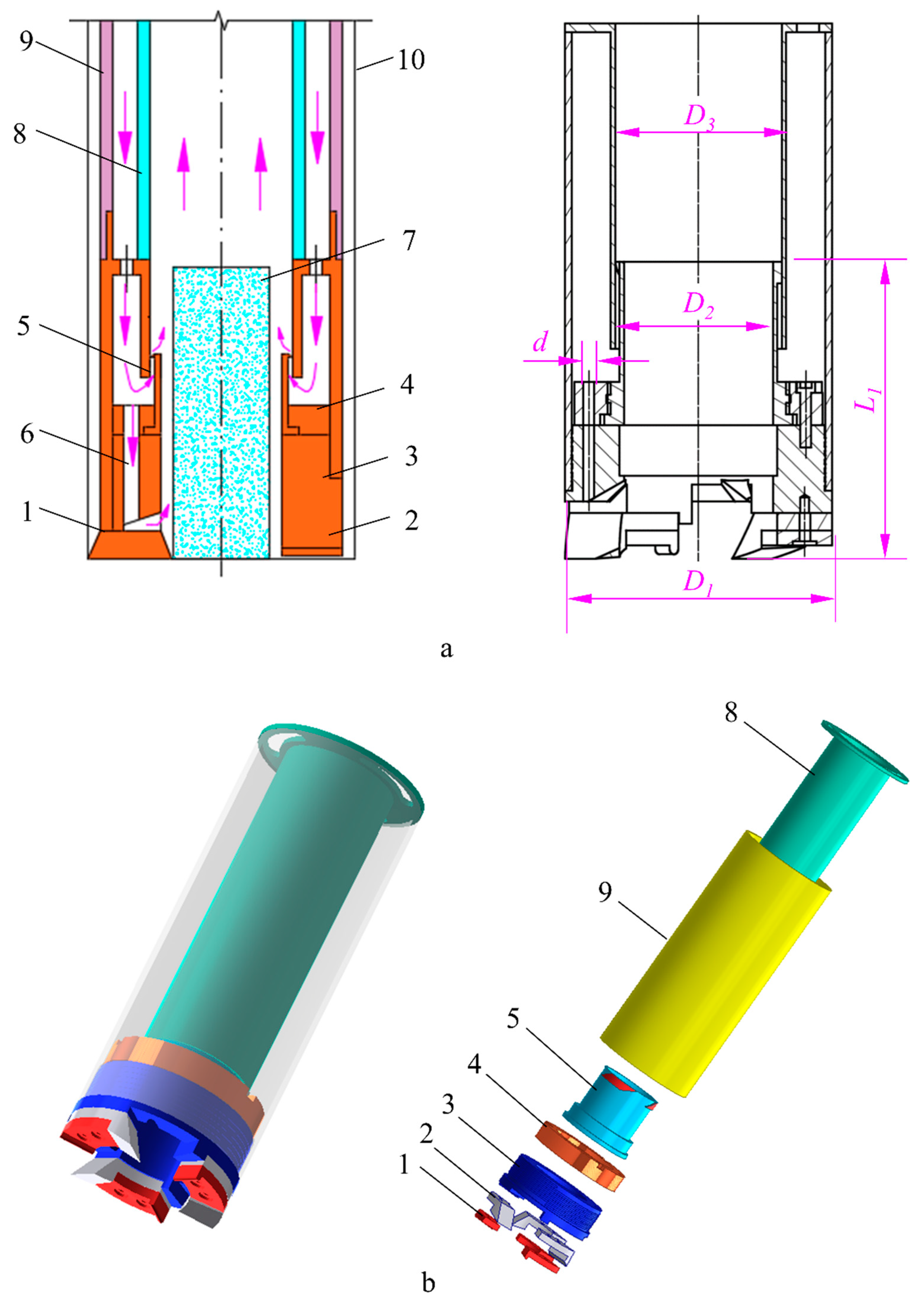
18], the swirling drill bit designed in this paper is shown in
Figure 1, which includes the lower and upper body of the drill bit, a vane swirler, inner and outer tubes, cutters, and the shoes. The outer wall of the swirler was designed with spiral blades that form spiral slots with the inner wall of the inner tube of the drill bit. After the high-speed flow of gas from the air compressor enters the drill bit through the annulus of the inner and outer tubes of the drilling bit, it is divided into two parts. One part is ejected from the swirler into the central passage, forming a swirling flow and generating negative pressure to suck the gas from the annular space between the drill bit and the borehole wall. The other part exits through the flushing nozzles and cools the cutters. The structural parameters of the drill bit are shown in
Table 1. Considering the low temperature of ice drilling, the cutters may not need to be cooled, so the flushing nozzles may not be needed. If this is the case, all of the air will pass through the swirler, thus, the reverse circulation effect will be greatly improved, and the drilling efficiency will also be increased.
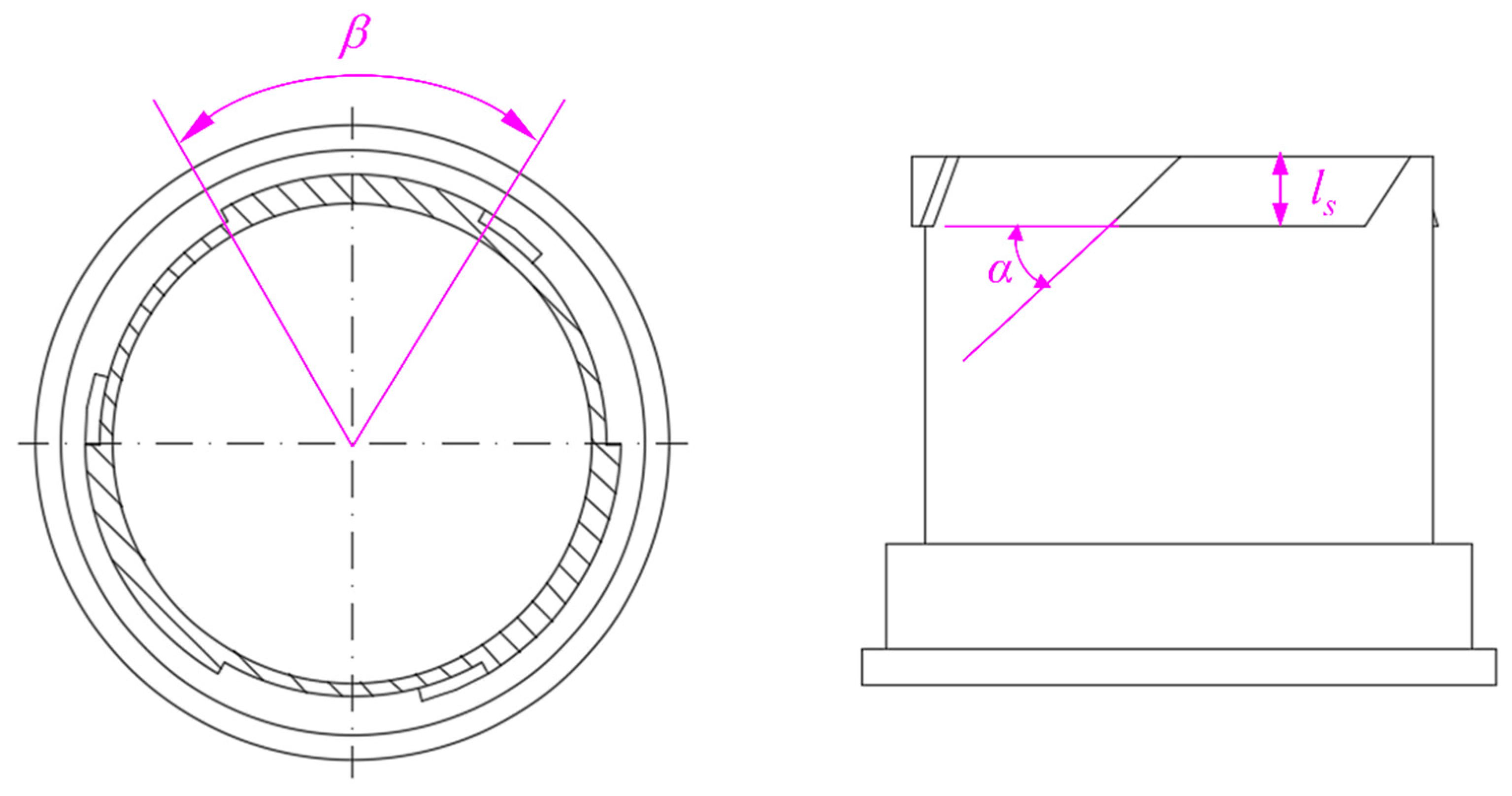
The structure of the swirler is shown in
Figure 2, and its structural parameters include the helical angle of the vane blade
α, the central angle
β, the blade length
ls, and the number of blades
n. Previous studies showed that the number and length of blades are secondary factors that influence the reverse circulation effect. When the number of blades is three and the height is 10 mm, the reverse circulation effect is better. This paper focuses on the effects of the helical angle and the area ratio on the reverse circulation effect by using CFD simulations. The area ratio,
λ, of the outlet of the swirler and the flushing nozzles can be controlled with the value of
β. The structural parameters of the swirler designed for this experiment are shown in
Table 2, and the experimental results can be used to verify the results of CFD simulations. When the reverse circulation effect is strong, the drill bit sucks air from the annulus between the drill bit and the borehole wall. In this paper, the entrainment ratio,
η, is adopted to evaluate the effect of reverse circulation, and it is given as:
in which
and
are the mass flow rate of the air supplied by the air compressor and the air sucked into the drill bit from the annulus between the drill bit and borehole wall, respectively (kgs
−1);
is the entrainment ratio of the drill bit and is dimensionless.
3. Numerical Simulation Procedure
3.1. Physical Model and Mesh Generation
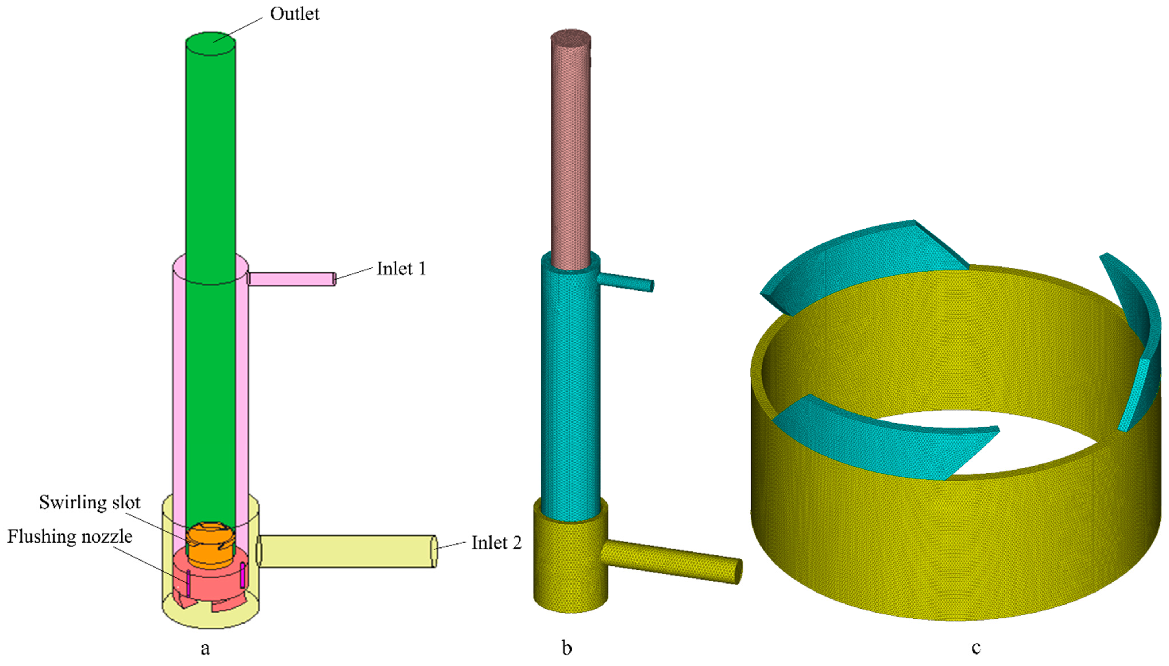
The swirling flow has a strong centrifugal force, and an inverse pressure gradient exists in the axial direction, making it easy to produce backflow. Therefore, the length of the central passage of the physical model must be long enough to avoid backflow at the outlet. After performing simulations, the necessary length of the central passage was found to be at least 1.2 m. A model of the drill bit is shown in
Figure 3a. Inlet 1 and Inlet 2 are connected to the air compressor and the atmosphere, respectively, and the drill bit sucks air from Inlet 2 when the reverse circulation is effective. As there are irregular shapes, such as cutter teeth and spiral blades, in the model, a tetrahedral mesh was used that is adaptable to the structure, and the areas with high velocity and a large pressure gradient, such as the flushing nozzles and spiral blades, are locally refined, as shown in
Figure 3b,c.
3.2. Governing Equations
The flow field of the swirling flow in the drill bit is more complex and difficult to theoretically analyze, but it can be analyzed with professional CFD software. The flow field in the drill bit is a steady-state form of three-dimensional compressible flow. The continuity equation, momentum equation, and energy equation are as follows:
Momentum:
where
V is the velocity vector,
u, v, and
w are the average velocity components,
are the corresponding varying velocity components, and
μ is the dynamic viscosity.
Energy:
where
,
k, and
are the heat capacity, heat transfer coefficient, and viscosity dissipation, respectively.
The equation of state for perfect gases is added in order to close the system:
Compared with other turbulence models, the Reynolds stress model (RSM) discards the isotropic eddy viscosity assumption and considers the effects of streamline curvature, vortex, and rotation, making the RSM more accurate than the one-equation and two-equation models. The RSM can capture the anisotropy of the strain in the flow field and predict the characteristics of the swirling flow more accurately. Hence, the RSM turbulence model is used in this paper, and the transport equation can be expressed as follows:
where the term on the left-hand side represents the convection, and the terms on the right-hand side represent the turbulent diffusion, molecular diffusion, stress production, buoyancy production, pressure strain, dissipation, production as a result of rotation of the system, and the user-defined source term, respectively.
3.3. Boundary Conditions and Numerical Scheme
A mass-flow-inlet boundary condition is used to describe the mass flow rate at Inlet 1. The mass flow rate is 0.052 kg/s, which corresponds to an air volume flow rate of 3 m3/min.
A pressure boundary condition is applied both to Inlet 2 and the outlet of the central passage. Inlet 2 and the outlet of the central passage are exposed to atmosphere in the simulation. Therefore, the magnitude of the gauge pressure is set to zero at these two boundaries. In addition, no-slip stationary wall boundary conditions are applied in the boundaries of the computational domain. The Coupled method is applied for pressure–velocity coupling. Moreover, a second-order upwind scheme is used for the momentum, turbulent kinetic energy, turbulent dissipation rate, and Reynolds stress equations.
4. Experimental Equipment
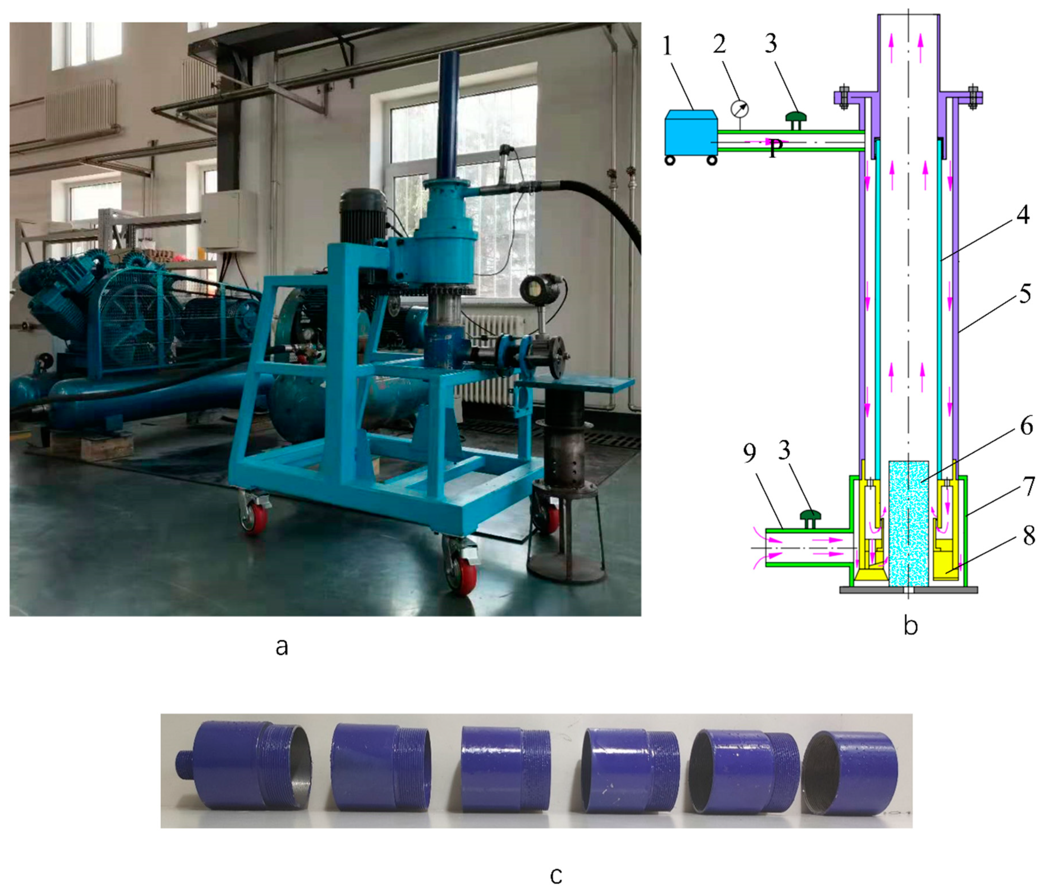
The testing stand is shown in
Figure 4. It was composed of a base frame, drilling tool, air compressor, and data acquisition system. The data acquisition system was composed of a temperature sensor, pressure sensor, and gas flow meter. LUGB-80 vortex flow meters were used to monitor the gas volume flow at Inlet 1 and Inlet 2 and the precision was 1.5%. An MIK-P300 pressure sensor was used to monitor the pressure
P at Inlet 1 and the precision 0.1%. A Pt-100 temperature sensor was used to measure the temperature of the gas. The experiment used a steel tube instead of the ice core; the diameter of the steel tube was 60 mm and its length was 40 mm. The upper and lower threads were set to facilitate replacement. In order to reduce possible experimental errors, each test was performed three times.
5. Results and Discussion
5.1. Grid Independence
The grid independence had to be analyzed before the formal simulations. The results of the simulations under different grid number conditions are shown in
Table 3. The number of grids of 1.33 million proved to be a critical point, as both the pressure at Inlet 1 and the air mass flow at Inlet 2 reached relatively stable levels when the number of grids exceeded 1.33 million. Considering the calculation time and accuracy, the number of grids used in this simulation was about 1.33 million.
5.2. Comparison of Simulated and Experimental Results
A minimum helical angle of 30°, helical angle of 60° and maximum helical angle of 90° were selected to compare the simulated and experimental results.
ηc and
ηo were used to represent the entrainment ratio in the drill bit without and with the flushing nozzle, respectively, and similarly,
Pc and
Po were used to represent the pressure at Inlet 1 of the two types of drill bits, respectively. As shown in
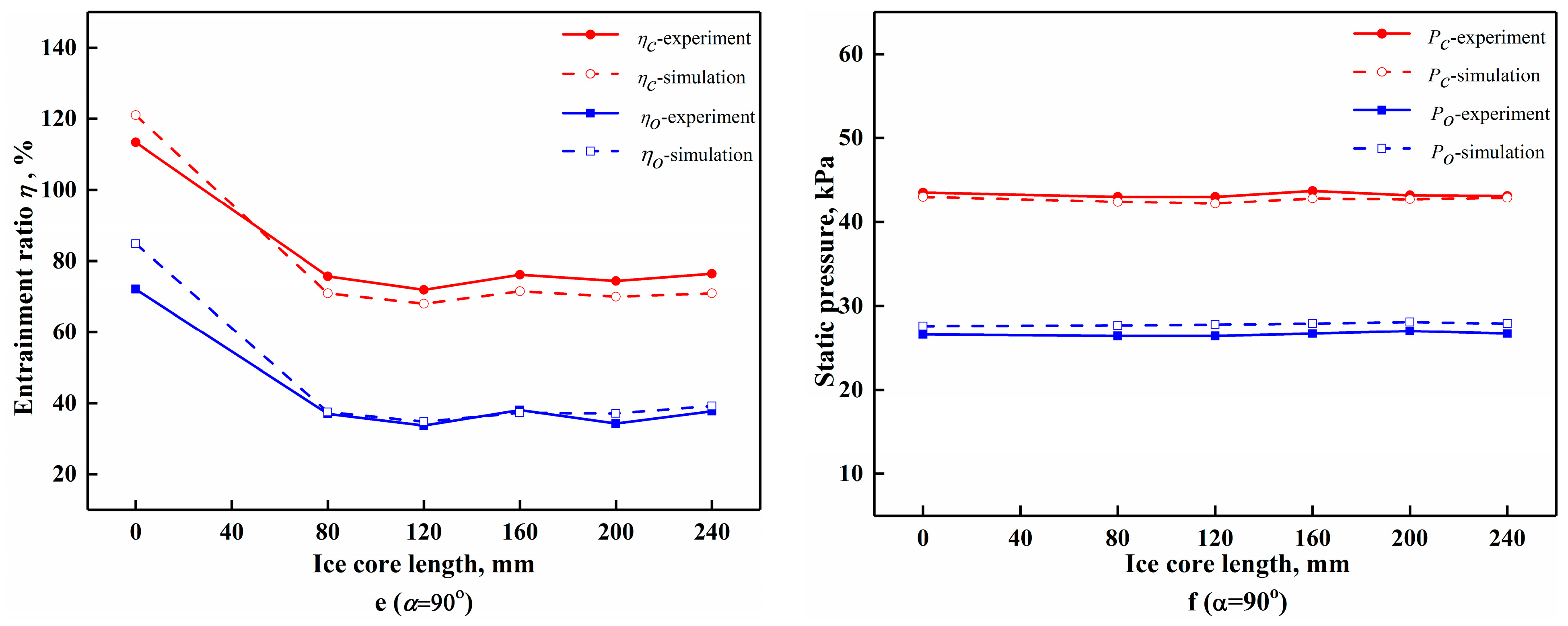
Figure 5, both the simulated and experimental results showed that the length of the ice core had a large effect on the entrainment ratio and a small effect on the pressure at Inlet 1, and the simulation results were in good agreement with the experimental results. For the swirling drill bit without the flushing nozzles and with the helical angle of 30°, with increase in the length of the ice core from 0 to 240 mm, the entrainment ratio decreased from 123.5% to 81.1% in the experiment, and it decreased from 131.2% to 78.5% in the simulation. The maximum and minimum errors between the simulated and experimental results were approximately 6.2% and 2.0% respectively. At the helical angle of 60°, the entrainment ratio decreased from 116.0% to 73.3% in the experiment, and from 127.6% to 70.8% in the simulation. The maximum and minimum errors were 10.0% and 0.6% respectively. At the helical angle of 90°, the entrainment ratio decreased from 113.4% to 76.4% in the experiment, and from 121.0% to 70.9% in the simulation. The maximum and minimum errors were 7.2% and 5.4% respectively. For the swirling drill bit with the flushing nozzles, the maximum and minimum errors were 17.6% and 0.7%, respectively, at these angles. The errors of the pressure at inlet 1 were less than 11%, regardless of whether there were flushing nozzles in the drill bit. Except for individual data points with large errors, the overall data had only small errors, which verified the accuracy of the simulation method.
5.3. Influence of the Helical Angle on the Entrainment Ratio
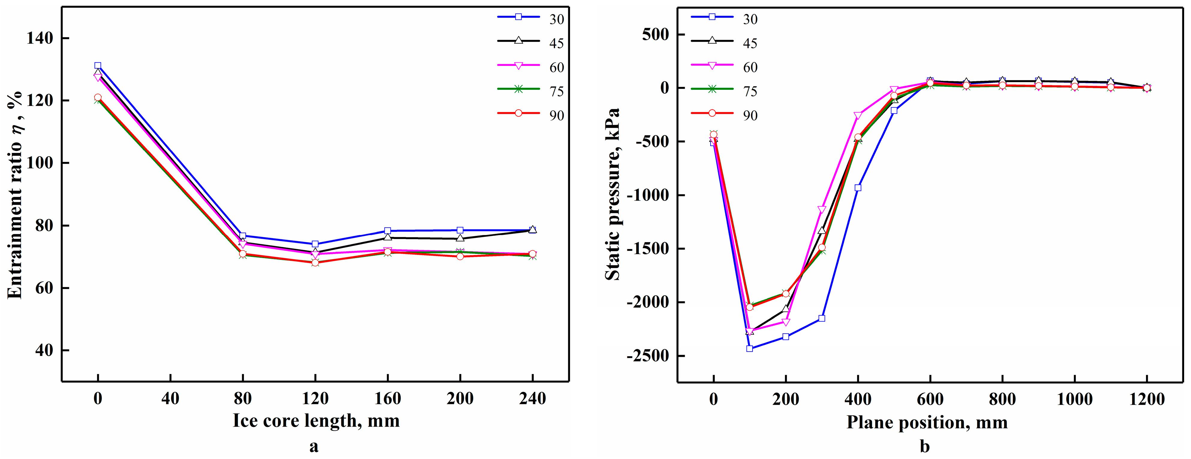
For the drill bits without the flushing nozzles, the simulated results of the entrainment ratio and the pressure distribution in the flow field for each helical angle are shown in
Figure 6. As shown in
Figure 6a, overall, the entrainment ratio of the drill bit decreased with the increase in the helical angle when the length of the ice core remained the same; the entrainment ratios of 45° and 60° were close, and those of 75° and 90° were also close. For example, when the ice core’s length was 80 mm, the entrainment ratio decreased from 76.7 to 70.9% when the helical angle increased from 30° to 90°. The variations in the plane pressure in the central passage with the distance from the bottom of the borehole are shown in
Figure 6b. When the reverse circulation effect was formed, the drill bit drew air from Inlet 2. The bottom of the borehole was closest to Inlet 2, so the higher the negative pressure at the bottom of the borehole was, the better the suction effect was. As shown in
Figure 6b, with the increase in the helical angle, the negative pressure at the bottom of the borehole gradually decreased, and when the helical angle increased from 30° to 90°, the negative pressure at the bottom of the borehole decreased from 514 to 432 Pa. When the helical angle was smaller, the tangential velocity of the airflow was larger, the intensity of the swirling flow was stronger, and the negative pressure that formed at the bottom of the borehole was greater. The area with the maximum negative pressure was located near 100 or 200 mm away from the bottom of the borehole. The outlet of the swirler was 145 mm from the bottom of the borehole. Air entered the central passage through the swirler and formed a swirling flow, and the negative pressure in this area is high. Overall, the maximum negative pressure gradually decreased with the increase in the helical angle, going from 2435 to 2048 Pa when the helical angle increased from 30° to 90°. Therefore, for the drill bits without the flushing nozzles, the smaller the helical angle was, the greater the negative pressure formed in the central passage and the better the suction effect. So, for the drill bits without the flushing nozzles, it is recommended to use a helical angle of 30°.
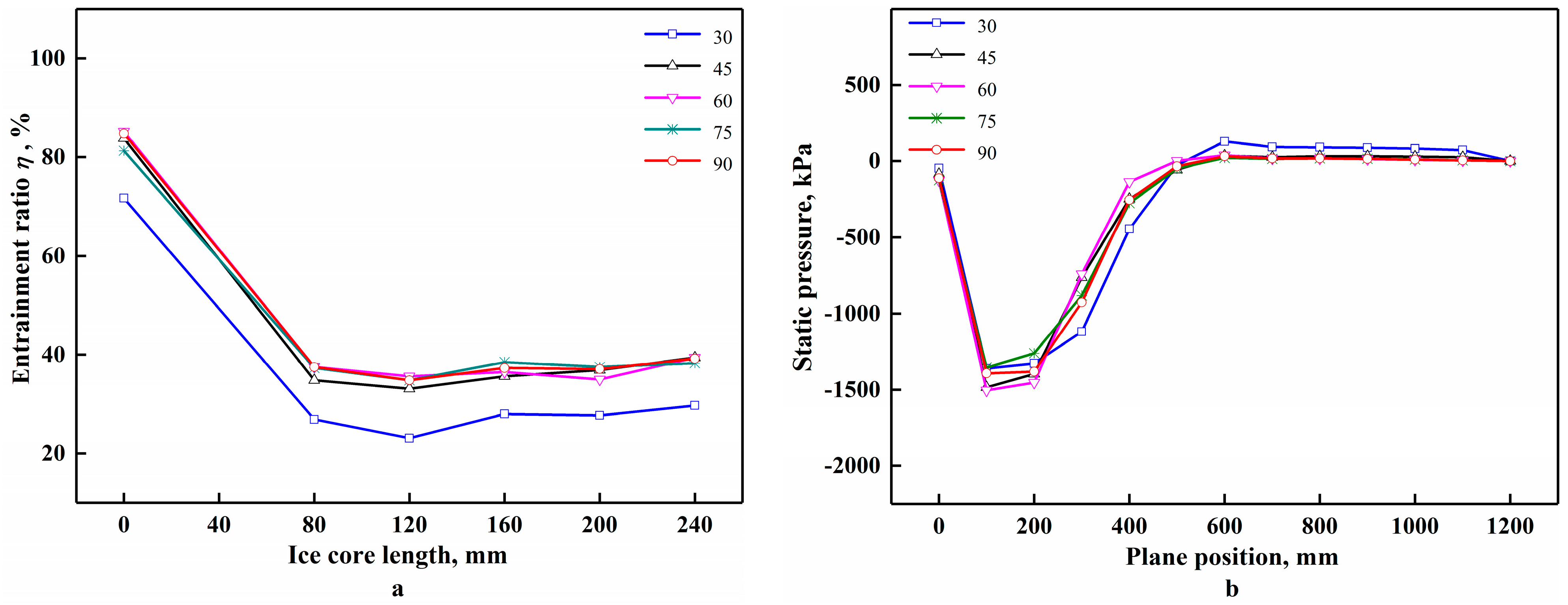
As shown in
Figure 7a, for the drill bits with the flushing nozzles, the entrainment ratio was much smaller compared to the drill bits without the flushing nozzles. Overall, the entrainment ratio of the drill bit increased with the increase in the helical angle when the length of the ice core remained same, though after the helical angle reached 60°, the entrainment ratio changed less. For example, when the ice core’s length was 80 mm, the entrainment ratio increased from 26.9 to 37.5% when the helical angle increased from 30° to 60°, and the helical angle continued to increase with smaller changes in the entrainment ratio. The distribution of the plane pressure in the central passage is shown in
Figure 7b. As shown in
Figure 7b, with the increase in the helical angle, the negative pressure at the bottom of the borehole gradually increased. When the helical angle increased from 30° to 60°, the negative pressure at the bottom of the borehole increased from 46 to 126 Pa. As the helical angle continued to increase, and the negative pressure varied less.
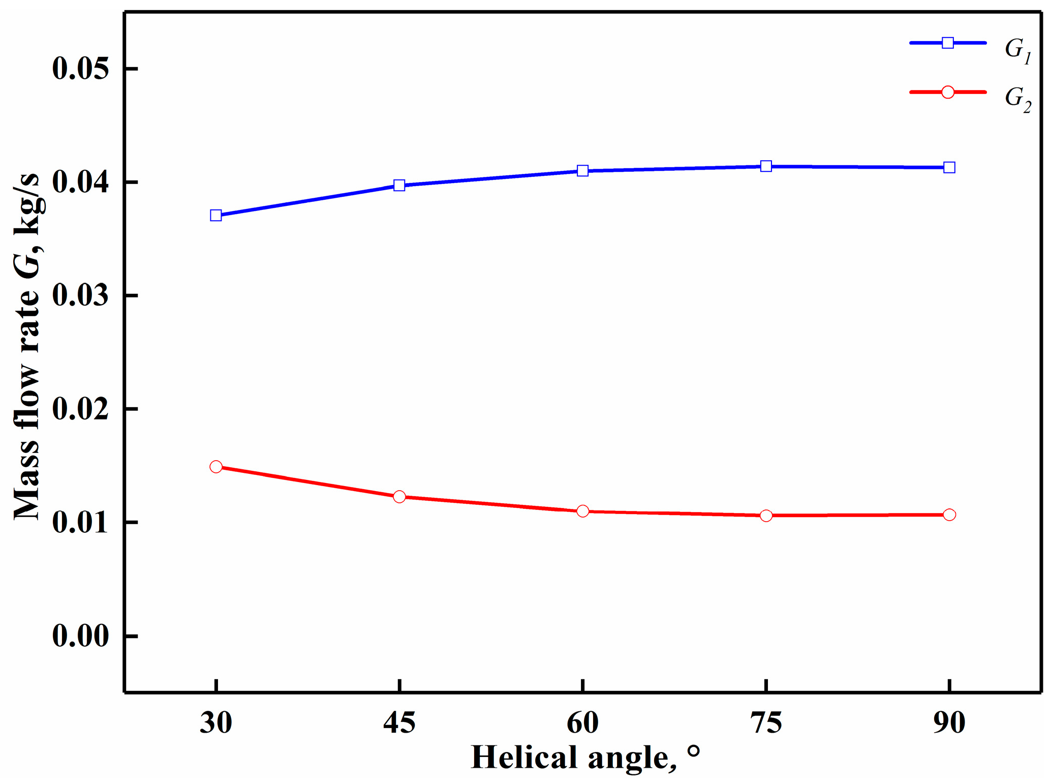
When the flushing nozzles were opened, the airflow in the drill bit was divided into two parts: One part was ejected from the outlet of the swirler, and the other part was ejected from the flushing nozzles. Changes in the helical angle of the swirler led to changes in the distribution of the flow rates of these two parts, which, in turn, affected the entrainment ratio of the drill bit. Through CFD post-processing, the mass flow rates of these two parts in the drill bit could be obtained separately and are referred to as
G1 and
G2, respectively.
Figure 8 exhibits the distribution of the mass flow rates of the two parts when the ice core’s length was 80 mm. It can be seen that the mass flow rate of gas through the swirler increased as the helical angle increased, and it remained essentially constant beyond 60°. With the increase in the helical angle from 30° to 60°, the mass flow rate of the gas through the swirler increased from 0.037 to 0.041 kg/s. When the helical angle was small, the resistance of the gas through the swirler was large, resulting in a decrease in the flow rate of the swirler and more diversion of the flushing nozzles. The flow rate through the swirler directly determined the velocity of the swirling flow that was ejected into the central passage. Although the swirling intensity at smaller helical angles was stronger, the flow rate through the swirler was lower, so the suction effect was poor. Therefore, if the flushing nozzles in the drill bit are opened, the entrainment ratio can be improved by increasing the helical angle. Therefore, for the drill bits with flushing nozzles, it is recommended to use a helical angle of 90°. From
Figure 6 and
Figure 7 it can be seen that the entrainment ratio is higher when there are no flushing nozzles in the drill bit, so it is recommended to use drill bits without flushing nozzles and with a helical angle of 30°.
5.4. Influence of the Area Ratio on the Entrainment Ratio
In order to study the influence of the ratio of the area between the outlet of the swirler and the flushing nozzles on the reverse circulation effect, the area ratio was adjusted by changing the center angle of the spiral blades while keeping the area of the flushing nozzles constant. As shown in
Figure 9a, for the drill bits without flushing nozzles, the entrainment ratio decreased with the increase in the area ratio. For example, when the ice core’s length was 80 mm, the entrainment ratio decreased from 82.3 to 66.5% when the area ratio increased from 3 to 6. If the flushing nozzles were closed, all of the air was ejected from the swirler into the central passage, and the area ratio had an important influence on the velocity of the swirling flow.
Figure 9b shows the maximum velocity of the swirling flow at the outlet of the swirler when the ice core’s length was 80 mm. It can be seen that as the area ratio increased, the maximum velocity linearly decreased; with the increase in the area ratio from 3 to 6, the maximum velocity decreased from 393 to 204 m/s. The greater the velocity of the swirling flow was, the greater the negative pressure that formed in the central passage and the stronger the suction capacity. The velocity of the swirling flow was greatest when the area ratio was 3. Therefore, for the drill bits without the flushing nozzles, it is recommended to use the area ratio of 3.
As shown in
Figure 10a, for the drill bits with flushing nozzles, the entrainment ratio increased with the increase in the area ratio. For example, when the ice core’s length was 80 mm, the entrainment ratio increased from 14.8 to 38.5% when the area ratio increased from 3 to 6. The mass flow rates of the air through the swirler and the flushing nozzles in the drill bit are shown in
Figure 10b. It can be seen that the area ratio had a great influence on the distribution of the flux in the drill bit. As the area ratio increased, the diversion of the flushing nozzles decreased, and the mass flow of air through the swirler increased. With the increase in the area ratio from 3 to 6, the mass flow rate of air through the swirler increased from 0.033 to 0.042 kg/s. As the flux through the swirler increased, the velocity of the swirling flow in the central passage increased, and the entrainment ratio increased. Therefore, if the flushing nozzles are opened in the drill bit, the entrainment ratio can be improved by increasing the area ratio of the swirler. So, for the drill bits with flushing nozzles, it is recommended to use an area ratio of 6. From
Figure 9 and
Figure 10 it can be seen that the entrainment ratio is higher when there are no flushing nozzles in the drill bit; therefore, it is recommended to use drill bits without flushing nozzles, with an area ratio of 3.
5.5. Influence of the Ice Core on the Entrainment Ratio
From the above discussions, it can be seen that the change in the ice core’s length has an effect on the entrainment ratio regardless of whether the flushing nozzles in the drill bit are opened. When the length of the ice core is zero, the entrainment ratio is the largest. When it is above zero, the entrainment ratio drops sharply and decreases gradually with the increase in the length. After it reaches 160 mm, the entrainment ratio rises slightly, and then fluctuates in a small range. When the air reverse circulation is formed, the air in the annulus between the drill bit and the borehole wall flows towards the annulus between the ice core and the central passage and then out of the annulus between the top of the ice core and the central passage. The distribution of the flow field in this region, from the annulus between the drill bit and the borehole wall to the annulus between the top of the ice core and the central passage, is critical to the analysis of the effect of the ice core on the entrainment ratio of the drill bit. As shown in
Figure 11, the annular surface P1 between the drill bit and the borehole wall to the annular plane P7 between the top face of the ice core and the central passage are the starting and ending planes of the flow field in this region. Planes P2–P6 are the five equally spaced faces between these. Plane P1 is 40 mm from the bottom of the borehole and planes P2–P7 are 40, 80, 120, 160, 200 and 240 mm from the bottom of the borehole in this order.
The pressure distribution in these planes for different ice core lengths is shown in
Figure 12. It can be seen that, regardless of whether the flushing nozzles are opened, the negative pressure of plane P
1 is at its maximum when the ice core’s length is zero. When the length is greater than zero, the negative pressure of plane P
1 decreases sharply, and the pressure loss between plane P
1 and P
2 increases dramatically. The reason for this phenomenon is that when the air at the bottom of the borehole flows to the central passage, it must bypass the ice core, and the size of the ice core is large, which leads to the separation of the boundary layer of the airflow and generates large pressure-drop resistance. When the ice core’s length increases from 80 to 120 mm, the annulus between the ice core and the central passage increases, the resistance along the path increases, and the negative pressure of planes P
1 to P
4 decreases. Planes P
5 to P
7 are above the outlet of the swirler, where the swirling flow mixes with the flow from the bottom of the borehole; momentum exchange occurs, and the pressure is not uniformly distributed. When the ice core’s length reaches 160 mm, it exceeds the outlet of the swirler and forms an annulus with the central passage, so the swirling flow maintains a high velocity, the negative pressure from planes P
1 to P
4 increases, and the entrainment ratio increases. However, due to the increase in the annulus, the resistance along the path increases and the space is narrow, which is not favorable for the expansion of swirling flow, so the entrainment ratio rises less.
5.6. Comparison of the Results of the Normal Drill Bit and the Swirling Drill Bit
At present, the commonly used air reverse circulation drill bits adopt inner nozzles as ejectors, and the airflow is ejected through a certain number of inner nozzles into the central passage, which sucks the air from the environment and forms a reverse circulation effect. It was found that the reverse circulation was better when the axis of the inner nozzles was at an angle of 60° with the horizontal direction [
16]. In order to compare the swirling drill bit with a normal drill bit, while keeping the other factors the same, the angles of the inner nozzles and the swirler were set to 60° and 30°, respectively. As shown in
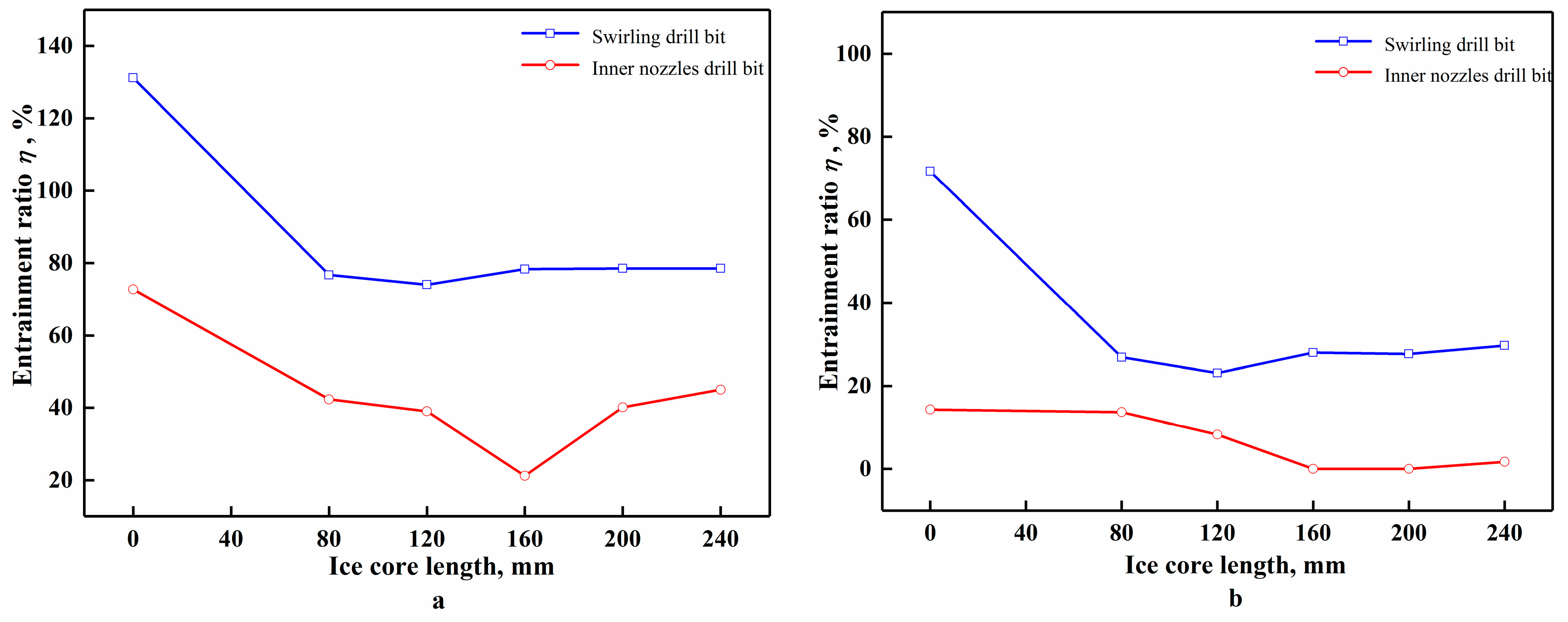
Figure 13, regardless of if the flushing nozzles were opened, the entrainment ratio of the swirling drill bit was greater than that of the normal drill bit at the same length of the ice core. When the flushing nozzles were closed, for the swirling drill bit, the maximum and minimum values of the entrainment ratio were 131.2 and 74.0%, respectively, but the values for the normal drill bit were only 72.7 and 21.2%. This indicates the high sucking capacity of the swirling flow. When the flushing nozzles were opened, the entrainment ratio of the normal drill bit dropped to zero after the ice core’s length reached 160 mm. This is because when the ice core exceeds the height of the inner nozzles, the airflow will impact the ice core when it is ejected into the central passage, resulting in a serious loss of momentum and a decrease in suction capacity. For the swirling drill bit, the airflow rose vertically after being ejected from the swirler into the central passage, and the annular space between the ice core and the central passage caused the swirling flow to continue to maintain a high velocity, so the entrainment ratio increased to a small extent.
6. Conclusions
The influence of the helical angle and area ratio of the swirling drill bit on the effect of reverse circulation were studied by means of CFD simulations, the influence of the ice core’s length on the entrainment ratio during core drilling was analyzed, and a comparison between the swirling drill bit and a normal drill bit was conducted. The following conclusions can be drawn:
(1) For drill bits without flushing nozzles, the entrainment ratio increases as the helical angle decreases. The smaller the helical angle is, the larger the negative pressure in the central passage will be, and the stronger the suction capacity will be. For drill bits with flushing nozzles, the entrainment ratio increases as the helical angle increases. With the increase in the helical angle, the mass flow of air through the swirler in the drill bit increases and the entrainment ratio increases.
(2) For drill bits without flushing nozzles, the entrainment ratio increases as the area ratio decreases. The smaller the area ratio is, the higher the velocity at the outlet of the swirler will be and the stronger the suction capacity will be. For drill bits with flushing nozzles, the entrainment ratio increases as the area ratio increases. The larger the area ratio is, the greater the mass flow of air through the swirler will be and the larger the entrainment ratio will be.
(3) Regardless of whether the flushing nozzles are opened, the presence of the ice core causes a dramatic decrease in the entrainment ratio. This is because when the airflow at the bottom of the borehole flows into the central passage, it needs to bypass the ice core, which generates a large differential pressure resistance and causes the suction capacity to drop rapidly. When the ice core’s length is greater than zero, the entrainment ratio decreases with the increase in the ice core’s length, and when the ice core’s length surpasses that of the outlet of the swirler, the entrainment ratio slightly increases.
(4) Compared with a normal drill bit, the swirling drill bit has a better suction effect. When the flushing nozzles are opened, if the ice core’s length is greater than that of the inner nozzles, the entrainment ratio of the normal drill bit decreases to zero, while the entrainment ratio of the swirling drill bit will slightly increase.
Author Contributions
Conceptualization: P.C. and M.W. (Mengke Wang); methodology: W.H. and M.W. (Mengke Wang); formal analysis: P.C. and M.W. (Mengke Wang); writing—original draft: M.W. (Mengke Wang); writing—review and editing: M.W. (Minqi Wang) and J.C.; validation: M.W. (Minqi Wang) and J.C.; investigation: M.W. (Mengke Wang) and W.H.; project administration: P.C. All authors have read and agreed to the published version of the manuscript.
Funding
This paper was supported by the National Natural Science Foundation of China (Project No. 41976213).
Institutional Review Board Statement
Not applicable.
Informed Consent Statement
Not applicable.
Data Availability Statement
Not applicable.
Acknowledgments
The authors thank the editors and reviewers for their constructive suggestions and comments.
Conflicts of Interest
The authors declare no conflict of interest.
References
- Igarashi, M.; Nakai, Y.; Motizuki, Y.; Takahashi, K.; Motoyama, H.; Makishima, K. Dating of the Dome Fuji shallow ice core based on a record of volcanic eruptions from AD 1260 to AD 2001. Polar Sci. 2011, 5, 411–420. [Google Scholar] [CrossRef] [Green Version]
- Segawa, T.; Ushida, K.; Narita, H.; Kanda, H.; Kohshima, S. Bacterial communities in two Antarctic ice cores analyzed by 16S rRNA gene sequencing analysis. Polar Sci. 2010, 4, 215–227. [Google Scholar] [CrossRef] [Green Version]
- Liu, A.; Wang, R.; Fan, X.; Yang, Y.; Li, X.; Wang, L. Test-Bed Performance of an Ice-Coring Drill Used with a Hot Water Drilling System. J. Mar. Sci. Eng. 2019, 7, 234. [Google Scholar] [CrossRef] [Green Version]
- Talalay, P.; Li, X.; Gong, D.; Fan, X.; Zhang, N.; Yang, Y. Design and experiment of clamper used in Antarctic subglacial bedrock drilling. J. Mar. Sci. Eng. 2019, 7, 153. [Google Scholar] [CrossRef] [Green Version]
- Talalay, P. Perspectives for development of ice-core drilling technology: A discussion. Ann. Glaciol. 2014, 55, 339–350. [Google Scholar] [CrossRef] [Green Version]
- Serbin, D.V.; Moiseenko, I.S.; Shadrin, V.S. Technologies and techniques for drilling wells in ice using the thermal method. Young. Sci. 2021, 27, 63–69. [Google Scholar]
- Bosikov, I.I.; Klyuev, R.V.; Gavrina, O.A. Analysis of geological and geophysical materials and qualitative assessment of oil and gas potential prospects in the South halbihinsky region (North Caucasus). Geol. I Geofiz. Yuga Ross. 2021, 11, 6–21. [Google Scholar]
- Talalay, P. Drill heads of the deep ice electromechanical drills. Cold Reg. Sci. Technol. 2014, 97, 41–56. [Google Scholar] [CrossRef]
- Talalay, P.; Yang, C.; Cao, P.; Wang, R.; Zhang, N.; Fan, X.; Yang, Y.; Sun, Y. Ice-core drilling problems and solutions. Cold Reg. Sci. Technol. 2015, 120, 1–20. [Google Scholar] [CrossRef]
- Cao, P.; Liu, M.; Chen, Z.; Chen, B.; Zhao, Q. Theory calculation and testing of air injection parameters in ice core drilling with air reverse circulation. Polar Sci. 2018, 17, 23–32. [Google Scholar] [CrossRef]
- Wang, R.; An, L.; Cao, P.; Chen, B.; Sysoev, M.; Fan, D.; Talalay, P. Rapid ice drilling with continual air transport of cuttings and cores: General concept. Polar Sci. 2017, 14, 21–29. [Google Scholar] [CrossRef]
- Cao, P.; Chen, Y.; Liu, M.; Chen, B.; Wang, J. Analytical and experimental study of a reverse circulation drill bit with an annular slit. Adv. Mech. Eng. 2016, 8, 1687814016669471. [Google Scholar] [CrossRef] [Green Version]
- Hu, Z.; Talalay, P.; Zheng, Z.; Cao, P.; Shi, G.; Li, Y.; Fan, X.; Ma, H. Air reverse circulation at the hole bottom in ice-core drilling. J. Glaciol. 2019, 65, 149–156. [Google Scholar] [CrossRef] [Green Version]
- Luo, Y.; Peng, J.; Li, L.; He, J.; Gan, X.; Yin, K.; Zhao, Z. Development of a specially designed drill bit for down-the-hole air hammer to reduce dust production in the drilling process. J. Clean. Prod. 2016, 112, 1040–1048. [Google Scholar] [CrossRef]
- Yin, Q.; Peng, J.; Bo, K.; He, J.; Kui, Y.; Gan, X. Study on dust control performance of a hammer drill bit. Int. J. Min. Reclam. Environ. 2013, 27, 393–406. [Google Scholar] [CrossRef]
- He, J.; Sun, B.; Liang, Y.; Luo, Y. Research on suction capacity and dust suppression performance of a reverse circulation air hammer in tunnel drilling. Tunn. Undergr. Space Technol. 2018, 71, 391–402. [Google Scholar] [CrossRef]
- Cao, P.; Chen, Y.; Liu, M.; Chen, B. Optimal Design of Novel Drill Bit to Control Dust in Down-the-Hole Hammer Reverse Circulation Drilling. Arab. J. Sci. Eng. 2017, 43, 1313–1324. [Google Scholar] [CrossRef]
- Cao, P.; Zhao, Q.; Chen, Z.; Cao, H.; Chen, B. Orthogonal experimental research on the structural parameters of a novel drill bit used for ice core drilling with air reverse circulation. J. Glaciol. 2019, 65, 1011–1022. [Google Scholar] [CrossRef]
- Elder, R.L. Advances of CFD in Fluid Machinery Design; John Wiley & Sons: New Jersey, NJ, USA, 2003; pp. 2–10. [Google Scholar]
- Eldrainy, Y.; Saqr, K.; Aly, H.; Jaafar, M. CFD insight of the flow dynamics in a novel swirler for gas turbine combustors. Int. Commun. Heat Mass Transf. 2009, 36, 936–941. [Google Scholar] [CrossRef]
- Beaubert, F.; Pálsson, H.; Lalot, S.; Choquet, I.; Bauduin, H. Fundamental mode of freely decaying laminar swirling flows. Appl. Math. Model. 2016, 40, 6218–6233. [Google Scholar] [CrossRef]
Figure 1.
Swirling ice core drill bit: (a) working principle of the swirling drill bit; (b) 3D models: (1) cutters; (2) shoes; (3) lower drill bit body; (4) upper drill bit body; (5) swirler; (6) flushing nozzles; (7) ice core; (8) inner tube of drill bit; (9) outer tube of drill bit; (10) borehole wall.
Figure 2.
Structure of the swirler.
Figure 2.
Structure of the swirler.
Figure 3.
Reverse circulation drill bit: (a) physical model; (b) integral mesh; (c) mesh of the swirler.
Figure 3.
Reverse circulation drill bit: (a) physical model; (b) integral mesh; (c) mesh of the swirler.
Figure 4.
Equipment for testing ice drilling with air reverse circulation: (a) experiment table; (b) schematic; (c) ice cores; (1) air compressor; (2) pressure sensors; (3) vortex flow meter; (4) inner tube of drill bit; (5) outer tube of drill bit; (6) borehole wall; (7) ice core; (8) drill bit body; (9) suction tube.
Figure 5.
Comparison of simulation and experimental results. (a) entrainment ratio of 30°; (b) static pressure of 30°; (c) entrainment ratio of 60°; (d) static pressure of 60°; (e) entrainment ratio of 90°; (f) static pressure of 90°.
Figure 5.
Comparison of simulation and experimental results. (a) entrainment ratio of 30°; (b) static pressure of 30°; (c) entrainment ratio of 60°; (d) static pressure of 60°; (e) entrainment ratio of 90°; (f) static pressure of 90°.
Figure 6.
Results of different helical angles for drill bits with flushing nozzles closed: (a) influence of helical angles on entrainment ratio; (b) pressure distribution of central passage.
Figure 6.
Results of different helical angles for drill bits with flushing nozzles closed: (a) influence of helical angles on entrainment ratio; (b) pressure distribution of central passage.
Figure 7.
Results of different helical angles for drill bits with flushing nozzles opened: (a) influence of helical angles on entrainment ratio; (b) pressure distribution of central passage.
Figure 7.
Results of different helical angles for drill bits with flushing nozzles opened: (a) influence of helical angles on entrainment ratio; (b) pressure distribution of central passage.
Figure 8.
Distribution of gas mass flow in the drill bit.
Figure 8.
Distribution of gas mass flow in the drill bit.
Figure 9.
Drill bits without the flushing nozzles: (a) influence of area ratio on entrainment ratio; (b) maximum velocity of gas at the outlet of swirler.
Figure 9.
Drill bits without the flushing nozzles: (a) influence of area ratio on entrainment ratio; (b) maximum velocity of gas at the outlet of swirler.
Figure 10.
Drill bits with the flushing nozzles: (a) influence of area ratio on entrainment ratio; (b) distribution of gas mass flow.
Figure 10.
Drill bits with the flushing nozzles: (a) influence of area ratio on entrainment ratio; (b) distribution of gas mass flow.
Figure 11.
Sketch map of plane position.
Figure 11.
Sketch map of plane position.
Figure 12.
Pressure distribution along different plane position: (a) drill bits without flushing nozzles; (b) drill bits with flushing nozzles.
Figure 12.
Pressure distribution along different plane position: (a) drill bits without flushing nozzles; (b) drill bits with flushing nozzles.
Figure 13.
Comparison of entrainment ratio between swirling drill bit and normal drill bit: (a) drill bits without flushing nozzles; (b) drill bits with flushing nozzles.
Figure 13.
Comparison of entrainment ratio between swirling drill bit and normal drill bit: (a) drill bits without flushing nozzles; (b) drill bits with flushing nozzles.
Table 1.
Structural parameters of the swirling drill bit.
Table 1.
Structural parameters of the swirling drill bit.
| OD/ID of Drill Bit Body, D1/D2, mm | ID of Swirler, D2, mm | ID of Inner Tube, D3, mm | Height of Swirler, L1, mm | Diameter of Flushing Nozzles, d, mm |
|---|
| 122/68 | 68 | 76 | 130 | 5 |
Table 2.
Structure parameters of the swirler.
Table 2.
Structure parameters of the swirler.
| Helical Angle α, ° | Area Ratio λ | Number of Blades n | Length ls, mm |
|---|
| 30 | 4 | 3 | 10 |
| 45 |
| 60 |
| 75 |
| 90 |
Table 3.
Results of the grid sensitivity analysis for the swirling drill bit.
Table 3.
Results of the grid sensitivity analysis for the swirling drill bit.
| Number of Cells (million) | Pressure at Inlet 1 (kPa) | Mass Flow Rate at Inlet 2 (kg/s) |
|---|
| 0.68 | 95.1 | 0.0683 |
| 1.03 | 94.7 | 0.0661 |
| 1.33 | 95.2 | 0.0641 |
| 1.54 | 95.1 | 0.0640 |
| 1.87 | 94.8 | 0.0643 |
| Publisher’s Note: MDPI stays neutral with regard to jurisdictional claims in published maps and institutional affiliations. |
© 2022 by the authors. Licensee MDPI, Basel, Switzerland. This article is an open access article distributed under the terms and conditions of the Creative Commons Attribution (CC BY) license (https://creativecommons.org/licenses/by/4.0/).


