Article

Experimental Evaluation of Shear Properties of Lightweight PVC Core for Marine Application Using Digital Image Correlation System

1
Department of Naval Architecture and Ocean Engineering, Faculty of Engineering, University of Rijeka, Vukovarska 58, 51000 Rijeka, Croatia
2
Department of Structural Engineering and Technical Mechanics, Faculty of Civil Engineering, University of Rijeka, Radmile Matejčić 3, 51000 Rijeka, Croatia
*
Author to whom correspondence should be addressed.
J. Mar. Sci. Eng. 2022, 10(2), 280; https://doi.org/10.3390/jmse10020280
Submission received: 25 January 2022 / Revised: 11 February 2022 / Accepted: 16 February 2022 / Published: 17 February 2022
(This article belongs to the Section Ocean Engineering)

Abstract

:
Sandwich structures are well-known and frequently used solutions in marine applications, especially when structural stiffness is required. An important part of the sandwich structure is the core, which usually carries shear loads. Therefore, choosing a reliable test method and knowing the exact shear properties of the particular core used in the structural design is beneficial for every engineer. Shear properties of the FlexyFoam M-55, a closed-cell, lightweight PVC foam with an apparent density of 60 kg/m3, have been investigated according to the ASTM C273 standard, using the tensile and compressive loading of metal supporting plates glued to the PVC foam sample. A digital image correlation (DIC) technique was used to monitor the crack propagation, and the appearance of secondary stresses at the foam-adhesive interface and strain field for the representative sample was presented. Displacement was measured using the testing machine sensors and compared to the measurements from the DIC technique. Specimen manufacturing details, surface preparation, and the gluing sequence were described, and measuring equipment and experiment settings were presented. Stress-strain curves have been presented and shear modulus and ultimate shear strength of the foam were compared for each test approach. The results were discussed and compared with the manufacturer’s data, as well as with foams of similar densities. The well-established approach in testing the core material was discussed, and recommendations were given to improve the testing procedure.

1. Introduction

The constant efforts of today’s marine and shipbuilding industry to improve its efficiency and competitiveness are reflected in the efforts to implement new technologies, procedures, and organisational methods in design, production and product exploitation. Hence, the application of composite sandwich structures in marine applications has been recognised as a valuable contribution to such efforts.
Composite sandwich structures are well-used in smaller vessels, as they are primarily known for their lightweight construction and exceptional stiffness. Recent trends in the shipbuilding industry have followed the small craft well-established principle of using sandwich panels in need of structural weight reduction and stiffness. This new trend has opened up a new path for creating a standardised and reliable data source on construction material and construction and testing methods [1]. The variety of materials used in composite production is increasing daily. Unlike in small craft production, where safety margins and risks are evaluated on a different level, and thus experimental evaluation of material properties is not mandatory, the production of large seagoing vessels needs reliable and accurate material data and approved testing methods. Collaboration between shipyards and class societies have yielded several projects and committees, like RAMSSES, ISSC, and increased practice of composites usage in parts or in large commercial and naval vessels, such as car decks in RO-Pax vessels [2] or even parts of the superstructures, hatch covers or in the construction of the structure of large commercial and naval vessels [3,4]. Therefore, composite sandwich panels and structures are an exciting go-to method for possible weight reduction issues.
The principle of sandwich structure is relatively simple, where the sandwich plate represents an I beam which consists of two faces (representing the flanges of the beam) on the top and bottom of the structure, having a core in between, acting as a web of I beams and making the necessary distance between flanges. The faces mostly take the normal stresses, while the core of the sandwich materials is usually stressed in shear. Therefore, the core is usually a different material from the faces spread out as continuous support for the faces [5]. Most used cores in the marine industry are foams both metallic [6] polymeric [2,7] as well as balsa wood [7] and honeycombs [7,8]. Other arrangements such as corrugated steel sandwich panels can also be used [9].
In the case of foam cores, mainly focusing on closed-cell PVC foams in marine structures, are predominantly cores of apparent densities ranging from 60 kg/m3 to 250 kg/m3, but reliable data for such cores are usually extracted from manufacturer technical data sheets (TDS) as shown in [5]. However, reliable stress-strain curves for these cores, especially shear stress-strain curves, are not readily available. The test results, curves and relevant data can be found for 80 kg/m3 to 250 kg/m3 (for Divinycell and DIAB foams) [10,11,12], but data for lighter foams are scarce. For lightweight closed-cell PVC foams of 60 kg/m3 or less, usually, only limited data based on manufacturer TDS is available. Hence, a FlexyFoam M-55 closed-cell, lightweight PVC foam with an apparent density of 60 kg/m3 was tested.
The shear properties of the core can be determined by following test and evaluation procedures described in [1]. Several test methods were described, composed of several ASTM and ISO standards. The most widely used are flexural tests, which tend to extract shear properties through the flexion of the sandwich beams utilising the 3-point or 4-point bending test [13,14]. Using the flexural test to extract the shear properties tends to be easier on the specimen production side, as the manufacturer of the vessel needs to provide just one type of testing specimen to extract multiple properties of the sandwich laminate. However, these tests provide approximate values as both the flexural and shear forces can influence the test results. Therefore, as advised in [15], both flexural tests should be performed. Special care should be executed when designing the test specimens for flexural testing, especially when performing the 3-point bending test, as the failure mechanisms during the test can lead to core indentation, face wrinkling or dimpling. The results for lightweight cores with a density less than 100 kg/m3 in most cases exhibit indentation [16,17,18], and therefore results obtained on these specimens cannot be taken into account when determining the shear properties of the core. The alternative testing methods for lightweight cores can be found in ASTM C273 [19] and similar ISO 1922 [20] standards. The test produces shear stress by moving the metal attachment plates parallel to the sandwich facing and covers the determination of shear strength parallel to the plane of the sandwich [19]. Using the methods described in the ASTM C273 and ISO 1922 standards, shear properties can reasonably easily be calculated since the shear failure of the core occurs even on lightweight, lower density cores.
This paper aims to present the ASTM C273 standard test method used to determine the PVC foam core shear properties and the sample preparation details in particular. It is noted that standards usually lack detailed instructions regarding sample preparation. Therefore, the authors have provided detailed information about the manufacturing process of samples with checks and dimension checklists needed to reproduce the specimens successfully. Recent development in DIC technology in the field of composites, especially foams [20,21,22,23,24], encouraged the authors to use the technology to evaluate the displacement of test specimens without the usage of different types of extensometers. Furthermore, shear tests were recorded using the DIC technology using 3D non-contact optical measurement based on the measured displacement field, thus enabling the calculation of shear stresses and shear modulus from DIC measurements. The shear modulus and the displacement of the grips on the testing machine were also recorded and compared to the values obtained with DIC measuring system. The difference was shown in shear test results for tensile and compressive loading arrangements, focusing mainly on the shear stress-strain curve and shear parameters for lightweight PVC foam core. In addition, DIC was used to visualise the strain field, animate the crack propagation, and monitor the parasitic effects that can occur at the core to adhesive interface [15]. The presented approach is expected to improve the maritime structures and ships design process, especially related to the core foam selection and sandwich structures definition.

2. Experimental Research

A specialised composite workshop conducted the specimen production and initial quality control. The apparent density of the materials was measured according to standard ISO 845:2006 [25] at the Faculty of Engineering, while ASTM C273 tests in tension and compression were performed at the Faculty of Civil Engineering, both University of Rijeka.

2.1. Material and Specimen Geometry

Tests were performed on FlexyFoam M-55, a closed-cell, lightweight PVC foam with an apparent density of 60 kg/m3. All test specimens were extracted from two FlexyFoam M-55 sheets, pre-cut by the manufacturer. The dimension of each sheet was 1270 mm × 2730 mm × 25 mm.
Foam density was measured according to ISO 845:2006 standard. The prismatic specimens were cut from three sheets and put to rest for 16 h in standard atmosphere conditions at 21 °C and relative humidity of 58%. Specimens are enumerated from Spec. 1 to Spec. 5, with specimen dimensions presented in Table 1. The average density of 57.3 kg/m3 was calculated as 4.5% less than the density declared by the manufacturer [26].
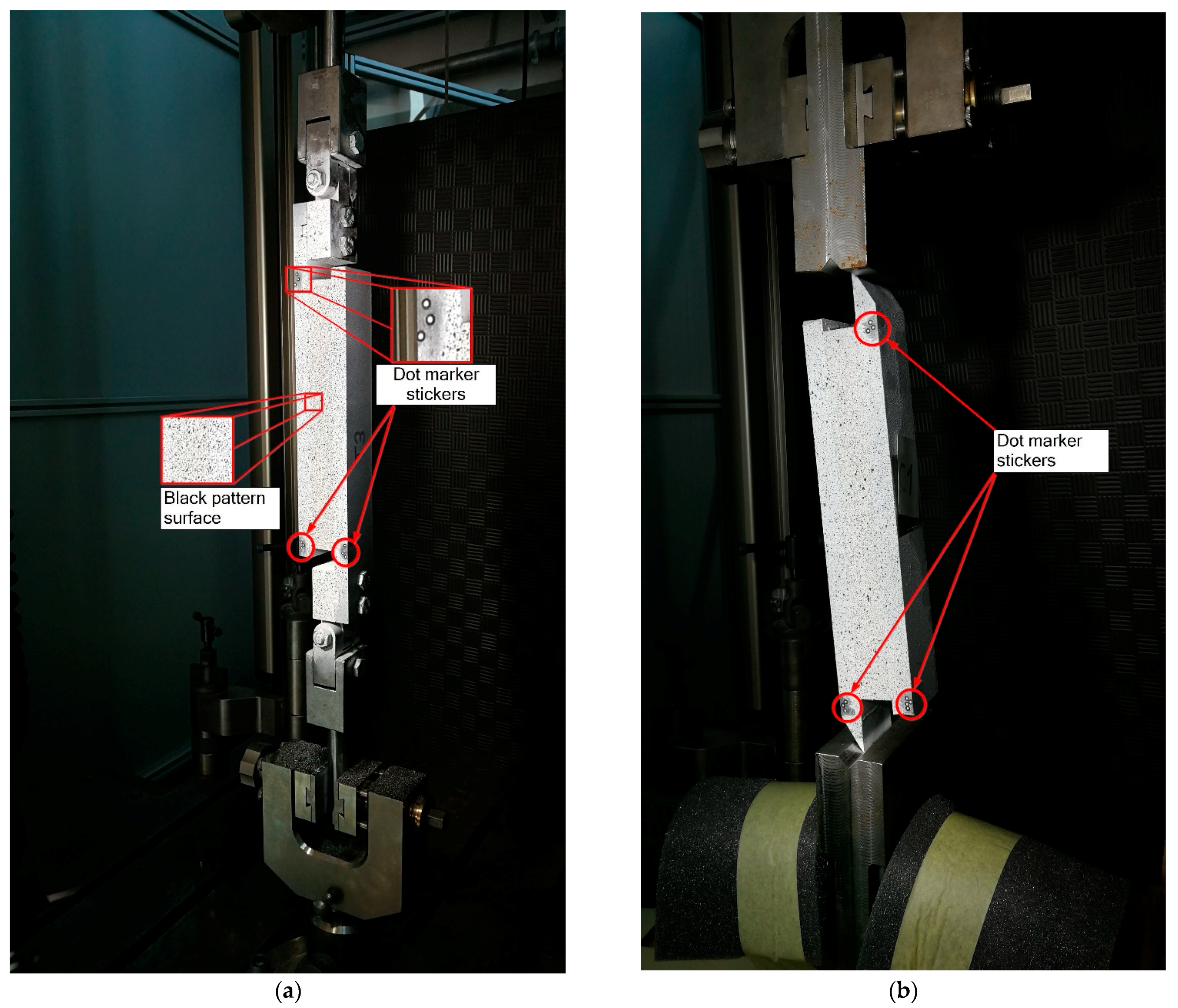
According to ASTM C273, the test specimen consists of a sandwich core material and metal loading plates attached to the tension and compression metal fittings (Figure 1). The samples are usually fitted into testing machine loading grips that transfer the shear force to the specimen. Different fittings were used to obtain shear stress in the specimen, by which the load in the specimen was applied in the tensile and compressive direction. Two different specimen configurations, one designed for the tensile direction of the load applied by the testing machine (Figure 1a) and one for the compressive direction, shown in Figure 1b. The metal fittings and specimen dimensions designed according to the ISO 1922 standard were used for specimens loaded in a tensile direction. Guidelines from ASTM C273 standard were used to create and adjust fittings and loading plates for the specimens loaded in a compressive direction. The loading plates and fittings were carefully designed to maintain the correct line of load, taking into account the thickness of the sandwich core material. The design of specimens and fittings vary depending on the direction of the load applied and grips used in the machine. A total of seven specimens were produced and tested in the tensile and 10 specimens in the compressive direction of the load.
The sandwich core material, a closed-cell, lightweight PVC foam with an apparent density of 60 kg/m3, for both test cases consisted of prisms with a standard size of approximately 250 mm × 50 mm × 25 mm. The core samples were glued to the loading plates made from grade A shipbuilding steel. Metal loading plates were grit blasted up to the grade of Sa 2 ½, degreased and cleaned prior to adhesion. Two-component epoxy adhesive, Araldite 2014-2, was used to bond steel loading plates and sandwich core material. The adhesive was cured at room temperature for 24 h achieving minimal lap shear strength of 10 MPa according to adhesive TDS [27].
The specimens were produced in two stages. First, one loading plate was positioned on a metal workbench to bond with the sandwich core material. The alignment of the core and metal plates was ensured using magnetic welding angles. The adhesive was applied to the loading plate, and sandwich core material was pressed with backing plates and secured using the F-clamps. The specimens were left to cure for 24 h at room temperature (23 °C) prior to the second stage, where the upper metal support plate was glued using a similar procedure. The adhesive was left to cure for 24 h at room temperature (23 °C). The excess material of the sandwich core that protruded outside the loading plate dimensions was sanded. The surface preparation of each loading plate, and the sandwich core material’s length, width and thickness were measured. Specimens were labelled using the letter T or C with an ordinal number of a specimen, where letter T marks the specimens intended for the tensile loading direction, while C stands for compressive loading direction. Seven specimens from T1 to T7 were produced to be loaded in the tensile direction, and 10 specimens marked C1 to C10 were produced for loading in the compressive direction. The sandwich core dimensions for each specimen are shown in Table 2.
Upon checking the dimensions of the finalised specimens, it was noted that the width of the sandwich core on all specimens except T4, T7, C4 and C7 differed from the required 50 mm as described in chapter 5.1 of the ASTM C273 standard. However, this deviation occurred during the production process, where the sandwich core was straightened and sanded to be level with the loading plates. The thickness of the tension specimens was below the designated sandwich core thickness, which may imply that the core was compressed during the production process. A slight angle between plates was noted when four thickness measurements were performed on each sandwich core material corner. The length of the sandwich core material in all specimens differed from the standard 12 times thickness recommendation provided in ASTM C273 standard. However, ASTM C273 standard allows deviation from the recommended dimension, so the design of the specimens loaded in the tensile direction corresponds to the ISO 1922 standard, while special care was taken to maintain the correct plane of loading in the specimens loaded in the compressive direction.
Finalised specimens were sprayed with white primer spray paint following the black pattern spray to ensure better visibility with the DIC system. In addition to the paint, dot marker stickers were attached to the supporting plate, and control dots were also attached to the machine grips to perform easier initial calibration of the system and provide reference points for a coordinate axis of the specimen coordinate system. The set-up of the finalised specimens, both loaded in the tensile and the compressive direction, is visible in Figure 2.

2.2. Test Set-Up and Equipment

The tests were performed on the universal tension-compression Zwick/Roell Z600 testing machine using a load cell of capacity 50 kN. Mechanical grips with a capacity of 10 kN were used. The tensile and compressive loads of the specimens were applied using the displacement control of the moving crosshead. The TestXpert II software was used to manage and register the data.
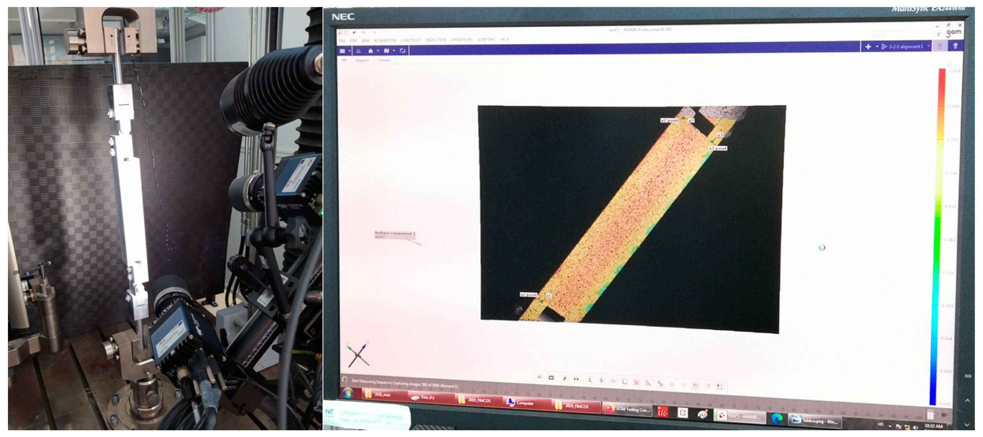
The displacement of the loading plates was measured using a DIC system, which consisted of an optical measuring system GOM gmbH PONTOS 3D 4M with two cameras of focal length 20 mm and LED spotlights mounted on the movable support (as seen in Figure 3). The maximum amount of 5000 images per experiment was defined, and the record speed of 5 fps was maintained through the complete experiment. The shooting angle was adjusted to capture the complete specimen and maintain the recommended 20° angle between the pair of cameras and the 500 mm distance from the samples. The DIC system was calibrated using standard procedure and aluminium calibration panel GOM/CP 20/MV 350 × 280 mm2. GOM software Aramis and Correlate were used for recording and data extraction. The surface component was used with a facet size of 16 pixels (area of 4.16 × 4.16 mm) with a centre point distance of 9 pixels, increasing the accuracy of strain and dimension measurement based on the digital images from different deformed stages [24].
Test procedures followed the guidelines provided in the ASTM C273 standard. Tensile specimens were conditioned for 6 h at a room temperature of 24.8 °C with a relative humidity of 46.6%. A constant test speed of 1 mm/min was introduced for tensile specimens.
Compressive specimens were conditioned at least 6 h at room temperature of 26 °C with a relative humidity of 48.6%. A constant test speed of 0.5 mm/min was introduced for compression specimens.
For both tension and compression loading arrangement, axial force and the displacement of the moving crosshead was measured using TestXpert II. The displacement of all specimens’ mounting plates and strain field was measured using DIC system GOM gmbH PONTOS 3D 4M with two cameras and recorded using ARAMIS software. The tests were carried until load applied on the specimen, measured on the testing machine grips, dropped below 80% of core breaking load.

3. Results and Discussion

Only the shear failure of the core was acceptable, while cohesive failure of the core to plate adhesive or adhesion failure of the core or plates was not acceptable according to the standard [19].
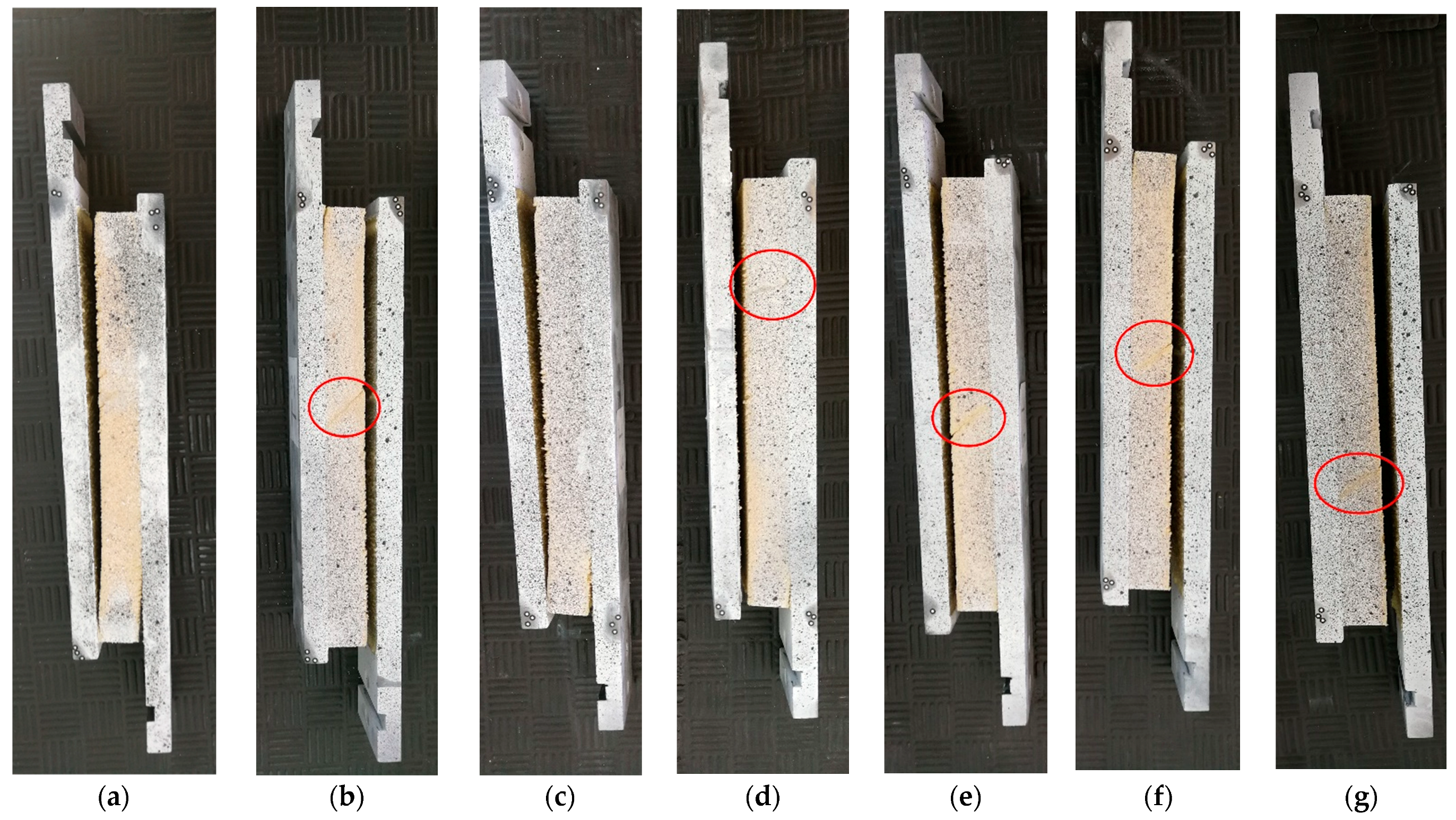
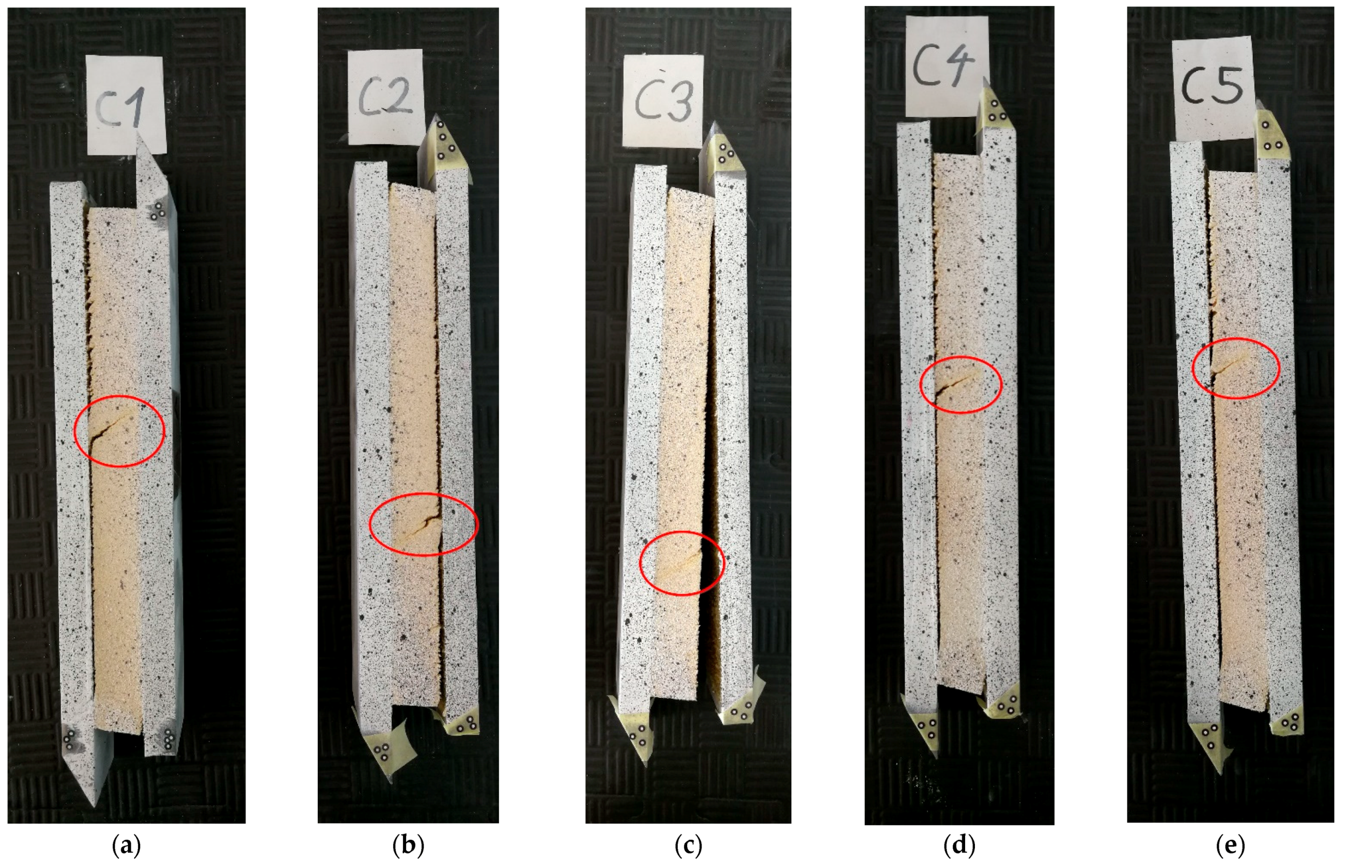
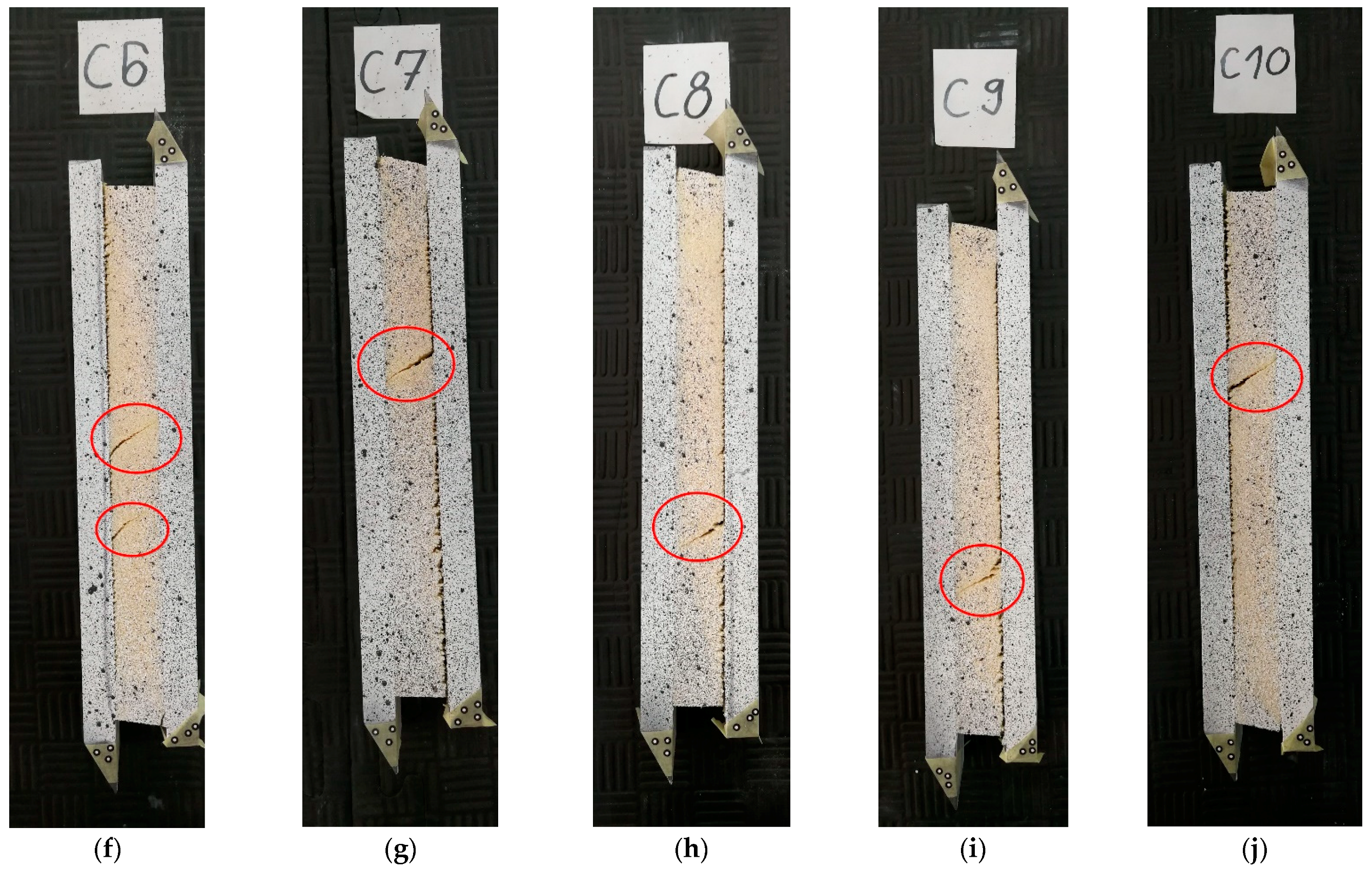
Through thickness crack is clearly visible on specimens T2 and T4 to T7. Upon detailed inspection of all specimens, it was noted that T1 and T3 specimens did not experience the trough thickness shear failure. Failure in the T1 and T3 specimens occurred in the sandwich core material but was limited to the plane parallel to the loading plates, a millimetre from the core-adhesive interface. No cohesive or adhesion failure was spotted in T1 and T3 specimens. The images of the specimens loaded in the tensile direction after the test can be seen in Figure 4. Specimens C1 to C10 all broke with the clear through thickness shear failure, as seen in Figure 5.
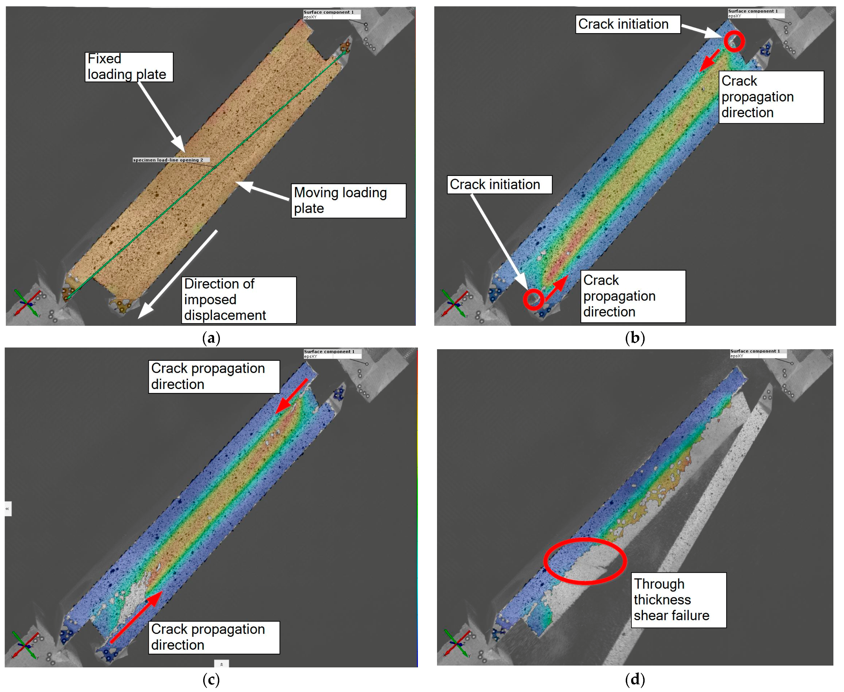
The crack propagation could not be measured directly, as the paint fell off alongside the PVC foam particles during the crack propagation due to sandwich core material behaviour. The larger area around the crack lost the paint, so the very tip of the crack could not be located precisely. However, it was possible to observe discolouration of the specimen during the experiment, especially in the DIC post-processing stage. The discolouration of the surface (due to the paint erosion from the PVC foam) was in-line with the later observed crack. The initial crack on all specimens started similarly. The crack occurred in the corner of the core, near the core to the steel plate interface. The crack initiation started in the area of the core subjected to the tensile load, confirming the observations made by [12] that the secondary stresses may occur in the core specimen, such that the tensile strain field may initiate the crack in the core. The tip of the crack was almost impossible to spot with the resolution and frequency of filming used in the current DIC measurement setup. However, the propagation of the crack and foam deformation was visible through the discolouration of the strain field.
Figure 6a depicts the test’s initial configuration and starting point for specimens loaded in the tensile direction, with the surface component showing values of γxy. Upon imposing the displacement on the movable loading plate, the crack on the specimen started to occur. The initiation and propagation of the crack could be made visible by tracking the grey areas on which software lost reference facets. Due to the nature of the sandwich core material, the loss of paint on surface components around the crack on PVC core foam was more significant than on the steel specimens. Therefore, the very tip of the crack was almost impossible to spot. However, the propagation path was clearly visible. The crack started near the lower edge of the core and propagated alongside the interface of core and adhesive in the direction of imposed displacement (visible in Figure 6b). When the lower crack expanded to 1/3 of the specimen length, a new crack started to form on the upper part of the specimen, near the moving loading plate (visible in Figure 6c). The test ended with trough thickness shear failure of the specimen, and through thickness crack is visible in Figure 6d. A similar process was observed on specimens loaded in a compressive direction, although the initiation of the crack on the opposite side occurred much earlier. The DIC measurement on the compression samples can be visible in Figure 7.
The images recorded with DIC were adequately synchronised with the force readings taken from the test machine during data post-processing. Overlapping timelines from the machine and DIC, it was possible to create load-displacement curves for each test. The shear stress τ, in MPa, and shear modulus G, in MPa, were calculated according to ASTM C273 standard. The average shear strength-strain curve was interpolated from experimental curves. The mean curve was interpolated using a Python script for curve interpolation created by authors. Inputs for the script were stress-strain curves for each group of specimens, thus calculating a separate mean curve for the tensile direction and a separate curve for the compressive direction of the applied load.
The resulting average shear stress-strain curve for specimens loaded in the tensile direction and curves for each specimen is shown in Figure 8. Specimens T1 and T3 were not included in the calculation of the average curve, as the specimens did not experience proper shear failure.
According to the DIC system, the specimens T2 and T4 to T7 exhibited shear failure at different displacements (dDIC) ranging from 4.68 mm to 7.06 mm. These values were compared to the measurements taken directly from the machine (dMACH). The comparison table is presented below; see Table 3, showing the difference Δd and giving the average difference of −1.24 mm between the two measuring methods.
The comparison of calculated shear modulus for the specimens T2 and T4 to T7, using the values from the DIC measurement (GDIC) and measurement calculated from the machine output (GMACH), and difference (ΔG) is presented in Table 4 with a calculated average difference of 2.6 MPa.
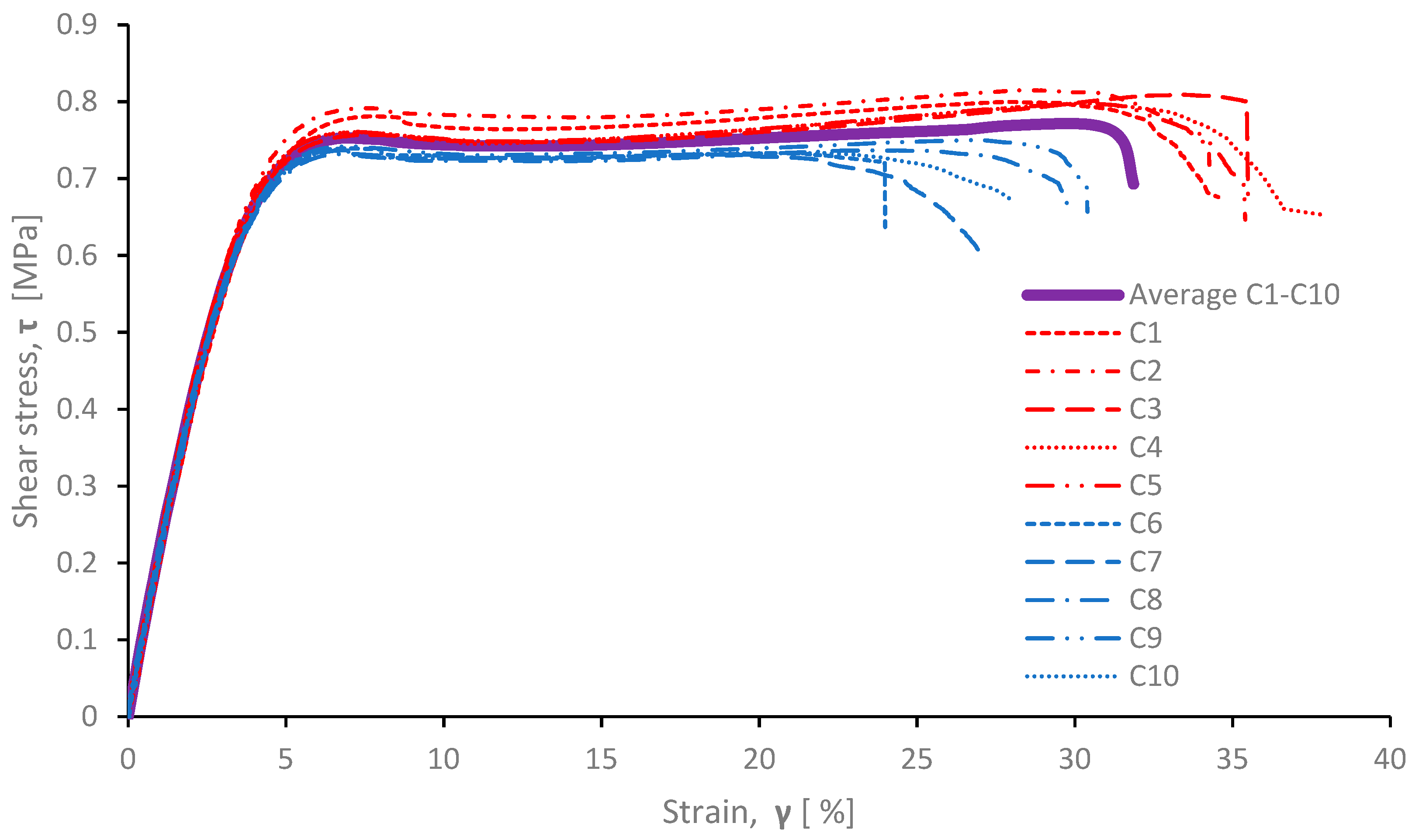
For specimens loaded in the compressive direction, the resulting average shear stress-strain curve and curves for each specimen separately are shown in Figure 9.
Specimens C1 to C10 exhibited shear failure in elongation range from 6.00 mm to 9.51 mm. The comparison between values measured using DIC system (dDIC) and measurements taken directly from the machine (dMACH) is given by the difference Δd value, see Table 5. The average difference is somewhat smaller than in samples loaded in the tensile direction, with a value of −0.72 mm.
The comparison of calculated shear modulus for the specimens C1 to C10, using the values from the DIC measurement (GDIC) and measurement calculated from the machine output (GMACH), is presented in Table 6. The average value of the difference is 6.8 MPa.
The grouping of the results for C1 to C5 (presented in red) and C6 to C10 (presented in blue) is also clearly visible. Due to the limited amount of sandwich core sheets available for testing, the sandwich core material for specimens was sampled on various positions on two different core sheets. Sandwich core material for specimens C1 to C5 was taken from one sheet, and for C6 to C10 specimens from another sheet. Due to manufacturing methodology, different parts of PVC foam can have slightly different properties, as PVC foam is usually cast into large blocks, and then they are cut in thin sheets prepared for sandwich construction, which may be the cause of the anisotropy and heterogeneity of core materials [28]. According to the author’s experience in the manufacturing procedures of the composite vessels, it is almost impossible for the vessel manufacturer to know the exact position of the sheets in the initial foam block. Therefore, the sampling process should involve samples from several sources and include different batches of the available core material.
The shear modulus calculated from the average curve of the specimens loaded in the tensile direction is 10.6 MPa. The lowest shear modulus of 9.9 MPa is calculated on specimen T5, whereas the highest shear modulus value is 11.9 MPa, calculated on T4. The shear modulus calculated from the average curve for the specimens loaded in compressive direction is 22.1 MPa. The lowest value for specimens loaded in compressive direction is 18.8 MPa, calculated for the C6 specimen. The highest shear modulus is 22.3 MPa, calculated for the C8 specimen. The average shear modulus calculated for all specimens is 16.4 MPa.
The shear modulus designated by the manufacturer in the product TDS [26] is 22 MPa, calculated using ASTM C393 standard. The average shear modulus for specimens loaded in the tensile direction is 52% lower than designated in the TDS [26]. The average shear modulus for specimens loaded in compressive direction differs from the designated modulus for just 0.5%, and it is slightly higher than stated in TDS [26]. However, the values provided by the author can also be compared to the values provided in [10], where shear modulus for foam with an apparent density of 80 kg/m3 is calculated at 18 MPa, while for foam with an apparent density of 100 kg/m3 shear modulus is around 25 MPa. TDS from yet another manufacturer [29] for the PVC foam cores provided a minimal value of 14 MPa, the maximal value of 21 MPa, and an average value of 17 MPa for shear modulus for foams with an apparent density of 60 kg/m3, tested and calculated using the ASTM C273 standard. These values indicate that the shear modulus for PVC foam of apparent density of 60 kg/m3 should be somewhat lower than 22 MPa in the expected range from 10 MPa to 20 MPa. Hence, it can be concluded that the specimens loaded in the tensile direction tend to give conservative values for the shear modulus of the foam. In contrast, values provided by specimens loaded in compressive direction are almost 20% higher than the shear modulus calculated for PVC foam of the apparent density of 80 kg/m3 provided in [10]. Such differences can result from different loading conditions occurring due to the loading in tensile and compressive directions. While cell walls of the closed-cell foams subjected to pure shear are subjected only to pure bending [30], the tensile or compressive components are added to total stress when parasitic stresses occur. Cell walls subjected to compression densify, thus adding to the strength of the material, while cell walls subjected to the tensile loading bend and stretch. Thus, additional stress predominant in the tensile direction causes brittle fracture of the cell walls, while additional compressive stress causes progressive crushing [30], which was somewhat captured using DIC. However, further study on the microscopical level is advised.
The authors of that article used the ASTM C273 standard to determine the shear properties of PVC foams, while the core manufacturer used ASTM C393 standard to determine the shear modulus. The ASTM C393 calculates the sandwich panel’s shear properties using the beam flexure, which includes yet another parameter to the equation, a sandwich panel facings. An expected facing ultimate strength needs to be known to correctly calculate shear modulus, while ASTM C273 standard does not include any additional material in the calculation. The authors’ shear modulus values are in line with known data for cross-linked, closed-cell PVC foams, especially if the mean value is calculated using the specimens loaded in the tensile and compressive direction.
The shear modulus values calculated from the machine given results tend to give a conservative estimation of the sandwich core shear modulus compared to the DIC measuring system method. The shear modulus of the specimens loaded in the tensile direction was lower by about 23% on average to DIC values, while for the specimens loaded in the compressive direction is about 32% on average lower than DIC values. Thus, a direct measurement from the machine could be taken for engineering purposes and a quick estimation of the properties of the lightweight sandwich material.
The shear stress values for each specimen are shown in Table 7, as well as the average values for specimens loaded in the tensile direction and specimens loaded in the compressive direction.
According to TDS provided by the manufacturer [26], the ultimate shear strength of the foam is 0.8 MPa. At the same time, average values for both types of specimens are lower than specified, 5.9% lower for specimens loaded in the tensile direction and 3.6% lower for specimens loaded in the compressive direction. However, they are higher than 0.7 MPa, provided in [5], and in line with recommended values from TDS [29], where 0.6 MPa is the minimal, and 0.77 MPa is the maximal value of the shear strength of the core.

4. Conclusions

The article focused on determining and validating the shear properties of lightweight cross-linked, a closed-cell PVC core, with an apparent density of the 60 kg/m3 used in a marine application, primarily in sandwich structures, thus giving initial data, mainly the shear stress-strain curve, for usage in preliminary structural design. The novel approach using DIC technology was presented, and results were discussed. On top of the information mentioned above, the following conclusions may be stressed:
  • The ASTM C273 gives conservative shear modulus values for specimens in the tensile loading direction, while specimens loaded in the compressive direction give very close values to the TDS and results provided by the manufacturer;
  • The shear strength of the core is marginally different from the value designated in the TDS. The values for the specimens loaded in the tensile direction are somewhat smaller than those loaded in the compressive direction;
  • The recommendation is to use ASTM C273 in both loading directions and perform apparent density measurement according to ISO 845:2006 standard;
  • The DIC method can easily substitute standard extensometers. The DIC is capable of measuring displacements and the strain field on the sample, but the method of tracking crack propagation on foam materials should be improved;
  • For a quick estimation of the shear modulus, the tests can be performed without DIC measuring system or the appropriate extensometer. However, these values tend to be conservative;
  • The sampling method in the vessel production can differ from the sampling methods during the core manufacturing. Proper sampling in vessel manufacturing conditions is usually hard to achieve as the samples are usually taken from the limited amount of available core sheets;
  • Taking all above mentioned into account, the authors stress the importance of verifying the material properties given by the manufacturer with experimental data prior to using them in any kind of calculations;
  • An additional result of the presented approach and experimental evaluation of shear properties is the possibility of using the obtained shear stress-strain curves within standard structural FEA procedures, as well as more advanced ones where it is necessary to create a new or modify an existing material model of the core.

Author Contributions

Conceptualisation, D.B., A.Z. and P.K.; methodology, D.B. and A.Z.; software, D.B.; validation, D.B., A.Z. and P.K.; formal analysis, D.B.; investigation, D.B.; resources, D.B., A.Z. and M.H.; data curation, D.B. and P.K.; writing—original draft preparation, D.B.; writing—review and editing, D.B., A.Z., P.K. and M.H.; visualisation, D.B.; supervision, A.Z.; project administration, D.B.; funding acquisition, A.Z. and M.H. All authors have read and agreed to the published version of the manuscript.

Funding

This research was funded by the University of Rijeka scientific research support project under grant number UNIRI PROJEKT tehnic-18-159 Development of Methodology for Ship Design and Productions towards Industry 4.0 Concept.

Institutional Review Board Statement

Not applicable.

Informed Consent Statement

Not applicable.

Data Availability Statement

The data presented in this study are available on request from the corresponding author.

Acknowledgments

Laboratory tests were conducted on equipment financed within the project Research Infrastructure for Campus-Based Laboratories at the University of Rijeka (no. RC.2.2.06-0001).

Conflicts of Interest

The authors declare no conflict of interest.

References

  1. Jang, J.-W.; Jeong, S.; Oh, D.; Cho, J.-H.; Noh, J. Test and Evaluation Procedure of Foam Core Materials for Composite Ships. J. Korean Soc. Mar. Environ. Saf. 2020, 26, 286–296. [Google Scholar] [CrossRef]
  2. Radolović, V.; Rahm, M. Design of Car Decks with Composite Panels Introduced on a 7000 Cars Car Carrier. In Proceedings of the E-LASS Conference, Pula, Croatia, 10–11 October 2017. [Google Scholar]
  3. Elenbaas, M. Custome Made Hull for Offshore Vessel. In Proceedings of the E-LASS Seminar Day, Online, 16 September 2020. [Google Scholar]
  4. Valbo, S. Visby Class Corvettes. In Proceedings of the E-LASS Seminar Day, Online, 27–28 January 2021. [Google Scholar]
  5. Zenkert, D. The Handbook of Sandwich Construction; Engineering Materials Advisory Services Ltd., Worley: West Midlands, UK, 1997. [Google Scholar]
  6. Filetin, T.; Marić, G.; Kramer, I. Metal Foams in Shipbuilding. Brodogradnja. 2005, 56, 228–237. [Google Scholar]
  7. Palomba, G.; Epasto, G.; Crupi, V. Lightweight sandwich structures for marine applications: A review. Mech. Adv. Mater. Struct. 2021, 1–26. [Google Scholar] [CrossRef]
  8. Bitzer, T. Honeycomb Marine Applications. J. Reinf. Plast. Compos. 1994, 13, 355–360. [Google Scholar] [CrossRef]
  9. Kujala, P.; Klanac, A. Steel Sandwich Panels in Marine Applications. Brodogradnja 2005, 56, 305–314. [Google Scholar]
  10. Daniel, I.M. Influence of Core Properties on the Failure of Composite Sandwich Beams. J. Mech. Mater. Struct. 2009, 4, 1271–1286. [Google Scholar] [CrossRef] [Green Version]
  11. Taher, S.T.; Thomsen, O.T.; Dulieu-Barton, J.M.; Zhang, S. Determination of mechanical properties of PVC foam using a modified Arcan fixture. Comp. Part A Appl. Sci. 2012, 43, 1698–1708. [Google Scholar] [CrossRef]
  12. Poapongsakorn, P.; Kanchanomai, C. Time-Dependant deformation of closed-cell PVC foam. J. Cell. Plast. 2011, 47, 323–336. [Google Scholar] [CrossRef]
  13. ASTM C393/C393M-16; Standard Test Method for Core Shear Properties of Sandwich Constructions by Beam Flexure. ASTM International: West Conshohocken, PA, USA, 2016. Available online: www.astm.org (accessed on 10 October 2021).
  14. ASTM D7250/C7250M-16; Standard Practice for Determining Sandwich Beam Flexural and Shear Stiffness. ASTM International: West Conshohocken, PA, USA, 2016. Available online: www.astm.org (accessed on 10 October 2021).
  15. Grédiac, M.; Dufort, L. Experimental Evidence of Parasitic Effects in the Shear Test on Sandwich Beams. Exp. Mech. 2002, 42, 186–193. [Google Scholar] [CrossRef]
  16. Gdoutos, E.E.; Daniel, I.M.; Wang, K.-A.; Abot, J.L. Failure Modes of Composite Sandwich Beams. Int. J. Damage Mech. 2002, 11, 309–334. [Google Scholar] [CrossRef]
  17. Steeves, C.A.; Fleck, N.A. Collapse mechanism of sandwich beams with composite faces and a foam core, loaded in three-point bending. Part I: Analytical models and minimum weight design. Int. J. Mech. Sci. 2004, 46, 561–583. [Google Scholar] [CrossRef]
  18. Steeves, C.A.; Fleck, N.A. Collapse mechanism of sandwich beams with composite faces and a foam core, loaded in three-point bending. Part II: Experimental investigation and numerical modelling. Int. J. Mech. Sci. 2004, 46, 585–608. [Google Scholar] [CrossRef]
  19. ASTM C273/C273M-16; Standard Test Method for Shear Properties of Sandwich Core Materials. ASTM International: West Conshohocken, PA, USA, 2016. Available online: www.astm.org (accessed on 10 October 2021).
  20. ISO 1922:2018; Rigid Cellular Plastics–Determination of Shear Properties. ISO: Geneva, Switzerland, 2018. Available online: www.iso.org (accessed on 10 October 2021).
  21. Voiconi, T.; Linul, E.; Marsavina, L.; Sadowski, T.; Kneć, M. Determination of Flexural Properties of Rigid PUR Foams Using Digital Image Correlation. Solid State Phenom. 2014, 216, 116–121. [Google Scholar] [CrossRef]
  22. Wang, P.; Pierron, F.; Thomsen, O.T. Identification of Material Parameters of PVC Foams using Digital Image Correlation and Virtual Fields Method. Exp. Mech. 2013, 53, 1001–1015. [Google Scholar] [CrossRef]
  23. Fathi, A.; Keller, J.-K.; Altstaedt, V. Full-field Shear Analyses of Sandwich Core Materials Using Digital Image Correlation (DIC). Compos. B Eng. 2015, 70, 156–166. [Google Scholar] [CrossRef]
  24. Krawczyk, L.; Goldyn, M.; Urban, T. Digital Image Correlation System in the Experimental Investigation: Capabilities and Limitations. Arch. Civ. Eng. 2019, 65, 171–180. [Google Scholar] [CrossRef] [Green Version]
  25. ISO 845:2006; Cellular Plastics and Rubbers–Determination of Apparent Density. ISO: Geneva, Switzerland, 2006. Available online: www.iso.org (accessed on 10 October 2021).
  26. Flexy Foam Datasheet, G. Angeloni. Available online: https://www.g-angeloni.com/elenco-prodotti/sanwich-cores/flexyfoam-pvc/ (accessed on 13 April 2021).
  27. Araldite 2014-2 Technical Data Sheet, Huntsman. Available online: https://www.intertronics.co.uk/wp-content/uploads/2015/12/ara2014-1.pdf (accessed on 24 January 2022).
  28. Chuda-Kowalska, M. Effect of the Foam’s Heterogeneity on the Behaviour of Sandwich Panels. Civ. Environ. Eng. Rep. 2019, 29, 97–111. [Google Scholar] [CrossRef] [Green Version]
  29. PVC 60 Foam Cores, CEL Composites. Available online: https://www.honeycombpanels.eu/en/products/foams/pvc-60-foam-core (accessed on 17 April 2021).
  30. Gibson, L.J. Cellular Solids; Cambrige University Press: Cambridge, UK, 1999. [Google Scholar]
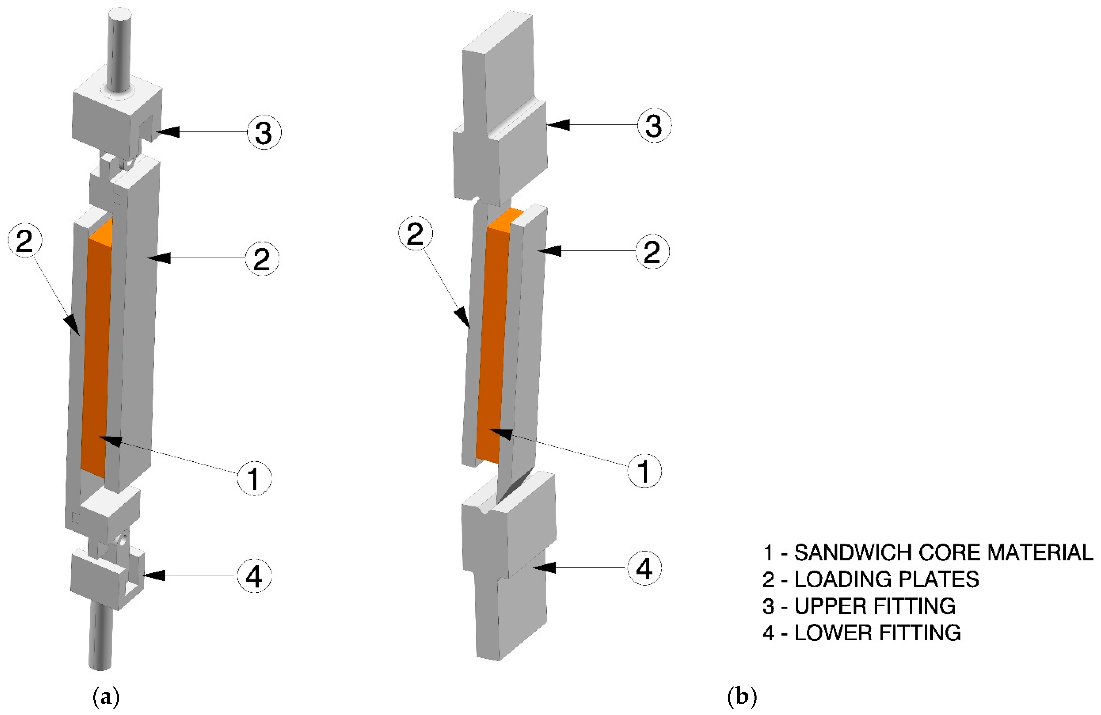
Figure 1. Schematic representation of the specimen designed according to the ASTM C273 standards for: (a) specimen loaded in the tensile direction; and (b) specimen loaded in the compressive direction.
Jmse 10 00280 g001
Figure 2. The set-up of the finalised specimens: (a) specimen T3 mounted in testing machine grips; and (b) specimens C1 mounted in testing machine grips.
Jmse 10 00280 g002
Figure 3. GOM PONTOS DIC system with ARAMIS software interface, ready for measurement.
Jmse 10 00280 g003
Figure 4. Specimens loaded in the tensile direction, shear failure position marked by red circles: (a) specimen T1; (b) specimen T2; (c) specimen T3; (d) specimen T4; (e) specimen T5; (f) specimen T6; and (g) specimen T7.
Jmse 10 00280 g004
Figure 5. Specimens loaded in the compressive direction with shear failure position marked by red circles: (a) specimen C1; (b) specimen C2; (c) specimen C3; (d) specimen C4; (e) specimen C5; (f) specimen C6; (g) specimen C7; (h) specimen C8; (i) specimen C9; (j) and specimen C10.
Jmse 10 00280 g005aJmse 10 00280 g005b
Figure 6. DIC measurement on T5 sample: (a) at the beginning of the experiment; (b) after the crack initialisation; (c) at crack occurrence on the opposite side; and (d) after the shear failure of the core. Red arrows represent crack propagation direction while measuring position is marked by green arrows.
Jmse 10 00280 g006
Figure 7. DIC measurement on C8 sample: (a) at the beginning of the experiment; (b) after the crack initialisation; (c) at crack occurrence on the opposite side; and (d) after the shear failure of the core. Red arrows represent crack propagation direction while measuring position is marked by green arrows.
Jmse 10 00280 g007
Figure 8. Shear stress-strain curve for specimens loaded in the tensile direction.
Jmse 10 00280 g008
Figure 9. Shear stress-strain curve for specimens loaded in compressive direction.
Jmse 10 00280 g009
Table 1. Apparent density measurements according to the ISO 845:2006 standard, presented for five foam specimens.
Spec. 1Spec. 2Spec. 3Spec. 4Spec. 5
Length * [mm]49.951.549.149.750.7
Width * [mm]43.142.849.743.249.7
Height * [mm]25.325.225.252.125.1
Volume [mm3]54,34055,58961,49654,05163,375
Weight [g]3.1583.1893.5913.1503.430
Apparent
Density [kg/m3]
58.1157.3758.3958.2854.12
* The mean values of three measurements.
Table 2. Sandwich core material dimensions: length (l), width (b) and thickness (t) for all specimens.
Specimenl [mm] b [mm]t * [mm]
Tensile Direction Specimens
T1254.2849.8924.46
T2255.0349.5124.76
T3251.4949.9725.15
T4251.0650.0824.99
T5251.5449.8724.75
T6253.1849.8224.58
T7254.7650.1024.54
Compressive Direction Specimens
C1255.4449.5024.89
C2251.9849.8825.06
C3253.2149.8325.08
C4254.2450.0825.17
C5254.2449.9125.17
C6254.1949.6425.02
C7254.5550.0725.10
C8254.2349.7325.15
C9252.2449.6725.13
C10260.0649.6025.12
* Average value of four measurements.
Table 3. Comparison table of displacement measurement for T2 and T4 to T7 specimens.
SpecimenT2T4T5T6T7
dDIC [mm]6.454.685.717.065.43
dMACH [mm]7.546.646.888.136.52
Δd [mm]−1.09−1.76−1.17−1.07−1.09
Table 4. Comparison of shear modulus measurements for T2 and T4 to T7 specimens.
SpecimenT2T4T5T6T7
GDIC [MPa]11.811.99.910.310.3
GMACH [MPa]7.88.88.67.98.3
ΔG [MPa] 4.03.11.32.42.0
ΔG [%]33.926.113.123.319.4
Table 5. Comparison table of displacement measurement for C1 to C10 specimens.
SpecimenC1C2C3C4C5C6C7C8C9C10
dDIC [mm]8.608.598.909.518.916.006.787.487.637.05
dMACH [mm]9.529.229.5010.059.706.607.948.118.417.61
Δd [mm]−0.92−0.63−0.60−0.54−0.79−0.60−1.16−0.63−0.78−0.56
Table 6. Comparison table of shear modules calculation for C1 to C10 specimens.
SpecimenC1C2C3C4C5C6C7C8C9C10
GDIC [MPa]19.321.322.321.121.218.819.522.321.121.3
GMACH [MPa]12.314.814.213.214.211.814.915.316.013.4
ΔG [MPa]7.06.58.17.97.07.04.67.05.17.9
ΔG [%]36.330.536.337.433.037.223.631.424.237.1
Table 7. Shear strength presented for all specimens.
Specimenτ [MPa]
T10.739
T20.773
T30.736
T40.743
T50.753
T60.761
T70.735
Average T1–T70.749
Average T2, T4–T70.753
C10.795
C20.815
C30.809
C40.798
C50.794
C60.739
C70.737
C80.737
C90.750
C100.737
Average C1–C100.771
Publisher’s Note: MDPI stays neutral with regard to jurisdictional claims in published maps and institutional affiliations.