Article

Genetic Algorithm for Sparse Optimization of Mills Cross Array Used in Underwater Acoustic Imaging

1
School of Marine Science and Technology, Northwestern Polytechnical University, Xi’an 710072, China
2
National Key Laboratory for Underwater Information Processing and Control, Northwestern Polytechnical University, Xi’an 710072, China
3
Beijing Institute of Radio Measurement, Beijing 100854, China
4
Department of Electrical Engineering-Electronics-Information Technology, Friedrich-Alexander University Erlangen-Nuremberg, 91054 Erlangen, Germany
*
Authors to whom correspondence should be addressed.
J. Mar. Sci. Eng. 2022, 10(2), 155; https://doi.org/10.3390/jmse10020155
Submission received: 26 November 2021 / Revised: 8 January 2022 / Accepted: 22 January 2022 / Published: 25 January 2022
(This article belongs to the Section Ocean Engineering)

Abstract

:
Underwater acoustic imaging employs a special form of array which includes numerous transducer elements to achieve beamforming. Although a large-scale array can bring high imaging resolution, it will also cause difficulties in hardware complexity and real-time application. In this paper, in order to reduce the number of array elements, a sparse optimization for Mills cross is proposed, considering the elements’ distributions and weights design. The improved genetic algorithm is adopted to generate evolutions for sparse solution. In order to ensure effective convergence and successful evolution, relevant genetic operators are proposed, including appropriate population coding, correct fitness function, reasonable selection strategy and efficient two-point orthogonal crossover, among others. Essentially, a satisfied sparse solution is a result of mutual restraint between array elements’ survivals and their weights. The simulations reveal that our sparse cross array decreases the number of elements by 8.25% compared to the conventional Mills cross multiplicative array, while keeping the advantages of narrow main lobe width and low sidelobe level. Improved genetic algorithm is an effective method for the underwater acoustic imaging array to implement the sparse optimization.

1. Introduction

Underwater acoustic imaging (UAI) has been widely used in underwater object recognition, underwater topographic survey, underwater archaeology, underwater operations and underwater equipment [1]. Compared with underwater optical imaging, UAI has the advantage of further visibility distance because of less acoustic transmission loss [2,3]. Nowadays, UAI becomes more useful in observing, recognizing or classifying underwater objects [4,5]. In UAI, a large-scale transducer array is usually developed to form a large number of beams, so a fast and efficient beamforming algorithm is needed for real-time and high-quality acoustic imaging [6,7]. However, complex hardware and heavy computation are the main obstacles in the development of UAI. To address the issues, cross array is an effective way to reduce the number of array elements compared to the classical rectangular planar array with same aperture, at the cost of higher sidelobes [8]. If one arm of cross array is used for transmitting and the other arm is used for receiving, the cross array with M + N elements will be equivalent to the rectangular array with M × N elements in the sense of sidelobe level [9]. The applications of cross array have been investigated over the past decades. In 1986, Okino et al. used a multi-narrow-beam sonar method to measure seabed topography. A transmitting linear array and a receiving linear array, perpendicular to each other, were employed individually [10]. In 1995, Alais et al. described a relatively simple acoustic imaging system, which used two orthogonal linear arrays with one for transmitting and the other for receiving [11]. It is possible to collect 3-D information by scanning a single beam over the region of interest if the acquisition time is not a problem [12]. The reason of consuming time lies in the combined scanning of every fan-shaped beam from transmitting array and fan-shaped beam from receiving array one by one. In addition, the two-way beam pattern is the product of the transmitting beam pattern and the receiving beam pattern [13]. Therefore, a cross array for the UAI system is promising owing to its advantages of obviously less array elements and acceptably low sidelobes, while suffering a relatively long imaging time. In order to further simplify array and shorten imaging time, the sparse array technique is worthy of consideration. Prior arts about sparse array design mainly rely on stochastic optimization, for instance, the genetic algorithm proposed by Holland [14], the simulated annealing algorithm proposed by Kirkpatric [15], the particle swarm algorithm proposed by Kennedy and Eberhart [16], among others. Fu et al. combined the genetic algorithm and simulated annealing algorithm to optimize an array and its weight. As a result, the sidelobes are lowered [17]. Modiri et al. improved the particle swarm algorithm and optimized a sparse array [18]. Li et al. used ADS (Almost Difference Set) and MIMO (Multiple Input Multiple Output) technology to obtain sparse cross array, which has the same angular resolution while only using fewer array elements compared with the original array [19]. All these previous studies provide insights into UAI [20].
This paper discusses a sparse optimization based on genetic algorithm for Mills cross multiplicative array, including the design of both array elements’ distribution and corresponding weights. Our aim is to reduce the hardware complexity and to improve the power efficiency for UAI. The method of improved genetic algorithm will be adopted, including two-point orthogonal crossover operator, elitism preservation strategy and so on. These operators are beneficial for fast convergence. All the work aims to reduce array elements, lower the sidelobes and shorten imaging time.

2. Mills Cross Multiplicative Array

A Mills cross array with two perpendicular linear arrays, one for transmitting and the other for receiving [21], has a multiplicative beam pattern that is the product of transmitting beam pattern and receiving beam pattern. Such a configuration is called Mills cross multiplicative array (MCMA) [22]. As a result, a simple MCMA can generate the same beam pattern as a conventional planar array with the same aperture.
Our Mills cross array, as shown in Figure 1, employs two arms of equispaced array, and its schematic configuration is shown in Figure 2. Assume that each arm consists of 4M + 1 transducer elements. There is one shared element located in the central position. The total number of elements is 8M + 1. The interval between the adjacent elements is d. If a far-field plane wave signal arrives from the direction characterized by the azimuth angle θ and the elevation angle φ, as shown in Figure 2, each arm can output the sum of the signals received by its individual element, namely A ( u ) e j ω t and B ( v ) e j ω t , respectively. A(u) and B(v) are voltage pattern, written as:
A ( u ) = m = 2 M 2 M a m e j k m d u
B ( v ) = n = 2 M 2 M b m e j k n d v
where am and bn are the weights of two arrays, k is the wave number, c is the speed of sound in water, ω is the angular frequency, u = sinθcosφ and v = sinθsinφ.
As a result, the voltage outputs of two arms are fed into a multiplier and are time-averaged to form the product pattern of MCMA, given by
P ( u , v ) = Re [ A ( u ) B ( v ) * ]
where * indicates complex conjugation.
For comparison, a conventional uniform rectangular planar array (RPA) with (2M + 1) × (2M + 1) equispaced isotropic elements is illustrated in Figure 3. We assume that element spacing is d and weight of every element is 1. The beam pattern of such a planar array is given by the product theorem [23], i.e.,
V ( u , v ) = C ( u ) D ( v )
where C(u) and D(v) are the voltage patterns of a line array parallel to sides of RPA for φ = 0 and φ = 90, respectively, expressed as
C ( u ) = sin [ 1 2 ( 2 M + 1 ) k d u ] sin ( 1 2 k d u )
D ( v ) = sin [ 1 2 ( 2 M + 1 ) k d v ] sin ( 1 2 k d v )
Then, the real power pattern of uniform RPA, after square-law detection, is given by
P ( u , v ) = [ C ( u ) D ( v ) ] 2
In order to obtain the same beam pattern of Mills cross array to the rectangular planar array, designing appropriate weights for the Mills cross array is feasible if the following equations are satisfied
A ( u ) = C 2 ( u )   and   B ( v ) = D ( v ) 2
Then, the weights of the MCMA will be obtained as
a m = 2 M + 1 | m | , 0 | m | 2 M b n = 2 M + 1 | n | , 0 | n | 2 M
where m and n are serial numbers of elements in Mills cross array. By using weighting given by Equation (9), the Mills cross array with 8M + 1 elements can produce the same beam pattern as a planar array with (2M + 1) × (2M + 1) elements.

3. Improved Genetic Algorithm

Reasonably reducing the element number of acoustic imaging array is desired because it is beneficial for shortening the imaging time and for reducing the hardware complexity. Of course, a premise is that the relevant performances should not be affected. As mentioned above, MCMA is an effective way to bring an amazing result in reducing the element number. In this paper, further reducing the number of elements of Mills cross array can be achieved by using the proposed improved genetic algorithm.
Genetic algorithm originates from Darwinian evolution. It uses mutation, crossover and selection procedures to breed better solutions from an originally random starting population [24]. Genetic algorithm provides an all-purpose framework to solve complicated optimization problems rather than the exclusive method of some certain kinds of problems. It can be applied in many domains such as biology, engineering, computer science and social science, among others. In this paper, an improved genetic algorithm will be employed for the sparse optimization of Mills cross array which is used in UAI. The detailed scheme of our improved genetic algorithm is illustrated in Figure 4. Firstly, for a problem, the algorithm genetically encodes the potential solutions and generates the initial population. Secondly, high-quality approximate solutions are selected by evaluating the fitness value of all the individuals. Then, the evolution procedure, one generation by one generation, will be executed iteratively through crossover, mutation and preservation operations until a certain individual meets the termination condition. The optimal solution will be obtained by decoding the result [25]. In order to ensure a successful evolution, the appropriate population coding and fitness function should be specified. Generally, the convergence of genetic algorithm is slow, especially for the case with large-scale genes in the chromosome and tremendous individuals in the population. In order to accelerate the convergence, two-point orthogonal crossover and elitism preservation operation are employed.
(1)
Population coding
We consider an equispaced linear array with N elements. The activation of each element is defined by a binary variable, where 1 indicates the element is activated while 0 indicates the element is not. Accordingly, the linear array can describe survivals of its elements through a binary vector
I = [I1, I2, …, IN], In = 0 or 1
If the weight of each element is designated, the weight vector for the array can be given by
w = [w1, w2, …, wN]
where wn is also binary coded. If I and w are combined, a long binary-encoded chromosome will be obtained, expressed as [I, w]. Such a chromosome includes a certain quantity of genes, which indicates whether an individual element of the array survives or not and shows the weight of each element. The initialization of all the genes is random, and an initial population will comprise of some different chromosomes.
(2)
Fitness function
The fitness function is employed to evaluate an individual, which outputs a nonnegative fitness value. An individual with a higher fitness value has a higher probability to be reproducted, while the one with a low fitness value has a relatively low reproduction probability, even causing extinction in evolution. In order to obtain low sidelobes for a linear array, the fitness function is proposed as:
F i t n e s s = | max θ , φ S ( 20 log n = 0 N 1 w n e j k n d u I n F F max ) |
where FFmax is the peak value of the main lobe, wn is the weight of the n-th array element, θ , φ S specify a reasonable sidelobe angular range. The lower the maximum sidelobe level is, the higher the above fitness value is, the more probably the corresponding chromosome survives.
(3)
Selecting operation
In order to survive high-quality individuals and to eliminate inferior individuals, it is necessary to select individuals based on their fitness values. Roulette selection [26] is one of the common methods. It mainly depends on the cumulative probability for selection. Generally, individuals with high fitness value have more chance to be selected. Note that some other selecting operations such as Stochastic Tournament, Excepted Value Selection, among others, are also feasible [27].
(4)
Two-point Orthogonal Crossover Operation
Orthogonal crossover operation, based on the orthogonal experiment, is proposed to make a systematic and rational search in the region defined by the parental solutions [28]. For the traditional crossover operation, the number of individuals after crossover operation will scale up with the increase in crossover points. The resultant excessive large population is terrible. It may cause a slow convergence speed. In order to accelerate convergence of the algorithm, multi-point crossover operations based on orthogonal design are effective [29,30], which can improve the probability for generating elite individuals.
In this paper, a two-point orthogonal crossover operator has been employed. Consider that the number of substrings needed to implement crossover in a chromosome is 3, namely the so-called three factor. Each factor has two possible values, a or b. That is to say, each factor has two levels. The number of offspring which are created by combining the parents at crossover point is 23 = 8. Considering the representative set of combinations, L8(27) orthogonal table, illustrated in Table 1, is employed to present the layout of two levels per factor and eight combinations of levels. In the above orthogonal design, seven factors have been simplified to three factors [31]. It is important that all the selected combinations are good representatives for all of the possible combinations. Finally, two offspring with higher fitness value after the crossover will be retained.
(5)
Mutation operator
Mutation operator is used to maintain genetic diversity from one generation of a population of genetic algorithm chromosomes to the next [32]. It is applied to mutate one or more gene values in a chromosome generated from the crossover operator. Hence, a better offspring may be evolved. Mutation occurs during the evolution according to a user-definable probability of mutation pmut.
(6)
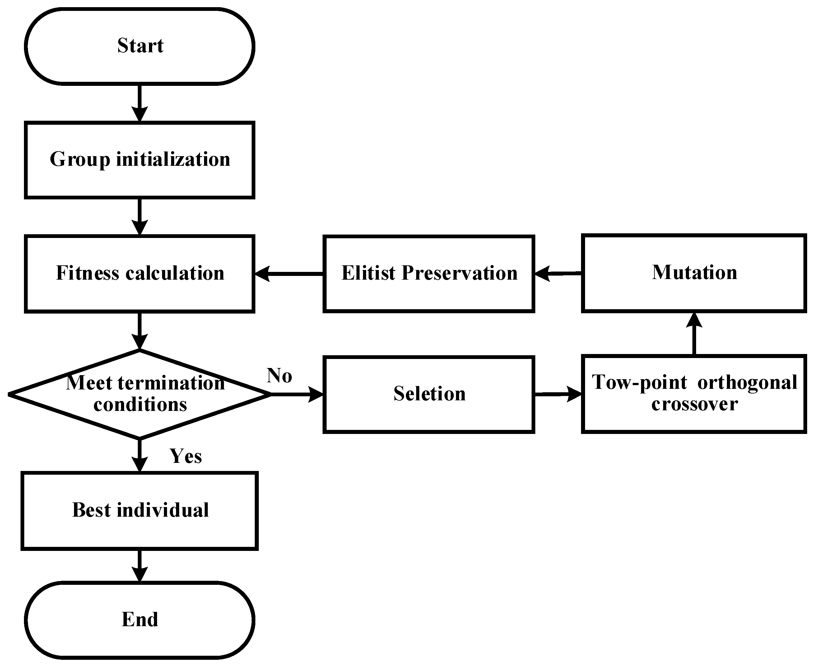
Elitist Preservation
During evolution of genetic operators, the best individuals of the previous generation can possibly lose their superiority and generate inferior individuals [33]. It will reduce searching efficiency of the genetic algorithm and even fail to converge to the optimal solution. Elitist preservation is to copy the best individual, so-called elitist, that has appeared in the whole evolved populations, directly to the next generation without a crossover operator. A common operator is that the worst individual will be replaced by an elite individual for the purpose of maintaining population scale. Elitist preservation operator will guarantee that some best solutions will be retained as elitist solutions, and the quality of the solutions will be improved iteratively.
The above operators will be applied in our improved genetic algorithm process, shown in Figure 4. After the evolution, high-quality solutions to optimization or search problems will be generated. During the process, fitness formulation, population size, probability of mutation, crossover and selection criteria should be carried out carefully. Any inappropriate choice will make it difficult for the algorithm to converge and even produce meaningless results [34].

4. Sparse Optimization of Mills Cross Array

Consider a Mills cross array with 49 + 49 equispaced elements. Its element spacing is 5 mm, as illustrated in Figure 2. Assume that the operating frequency is 150 kHz. According to the theory of Mills cross multiplicative array, it will produce the same pattern as a rectangular planar array with 25 × 25 elements when its weights are appropriate. The beam patterns of MCMA and RPA are shown in Figure 5, respectively. Both arrays produce main lobe width of 4.08° and the maximum sidelobe level of −13.5 dB. However, MCMA reduces the number of elements by 528 elements compared with RPA. The reduction in array scale will be beneficial for UAI application.
In order to further reduce the number of elements of imaging array without lowering the sidelobe level, improved genetic algorithm operators are proposed to obtain a satisfied sparseness solution for Mills cross array. The variables to be optimized include the locations and weights of each element. In other words, whether the array elements are active or not and their weights will be determined. Assume that the weights obtained from Equation (9) are provided for an initial individual, and the variation range of weights is designated from 0 to 127. Its binary code length is 343 bits. We set up an initial population including 50 individuals. The maximum genetic generation is 200,000, the mutation probability is 0.007 and the crossover probability is 0.3. The symmetry of array element and their weights about central element is considered in our algorithm.
The improved genetic algorithm has been employed to evolve an optimized sparseness solution to our Mills cross imaging array. Although the genetic algorithm-based optimization method is implemented at the cost of a higher computational complexity, it is still valuable and effective for the reduction in the scale of the array. In other words, the MCMA optimized by our proposed improved genetic algorithm has a lower hardware complexity and a lower power consumption. This is cost-effective and beneficial to the battery limited UAI devices in practical applications. The distributions of array elements before and after optimization are illustrated in Figure 6. Compared with 97 elements of the original MCMA, the sparse cross array (SCA) after optimization has 89 elements. The number of elements is decreased by 8.25%. The unused elements are mainly located in the external terminal of the array. Figure 7 illustrates the weights of MCMA and SCA for similar beam indices, especially the beamwidth and maximum sidelobe level. It is obvious that the weights vary distinctly. Firstly, orderliness of weights changes from a regular cone-shaped distribution of MCMA to an approximate cone-shaped distribution of SCA. Secondly, values of weights change a lot. For instance, the weights near the center of SCA are amplified by nearly one time relative to MCMA. The above two changes interrelate. The ultimate purpose is to keep similar beam indices.
Figure 8 illustrates beam patterns at Φ = 0° or 90°, obtained from MCMA, SCA and cross array with conventional beamforming, respectively. Their main pattern indices are listed in Table 2. The beamwidth is 4.76° for SCA. Compared with 4.08° for MCMA and 3.15° for cross array with conventional beamforming, SCA provides a slightly wider main lobe. Actually, the difference is small and acceptable. However, SCA demonstrates its advantage in maximum sidelobe level of −14.27 dB. It lowers the level by about 9 dB than cross array with conventional beamforming and has the same level as MCMA.

5. Conclusions

For the purpose of reducing the scale of acoustic imaging array and imaging time, a sparse cross array was presented. The elements’ distributions and weights of the array were optimized using improved genetic algorithm. Relevant operators were proposed to compel genetic algorithm to converge to a satisfactory solution effectively. By comparing beam pattern indices of different imaging array, the following conclusions can be drawn.
(1)
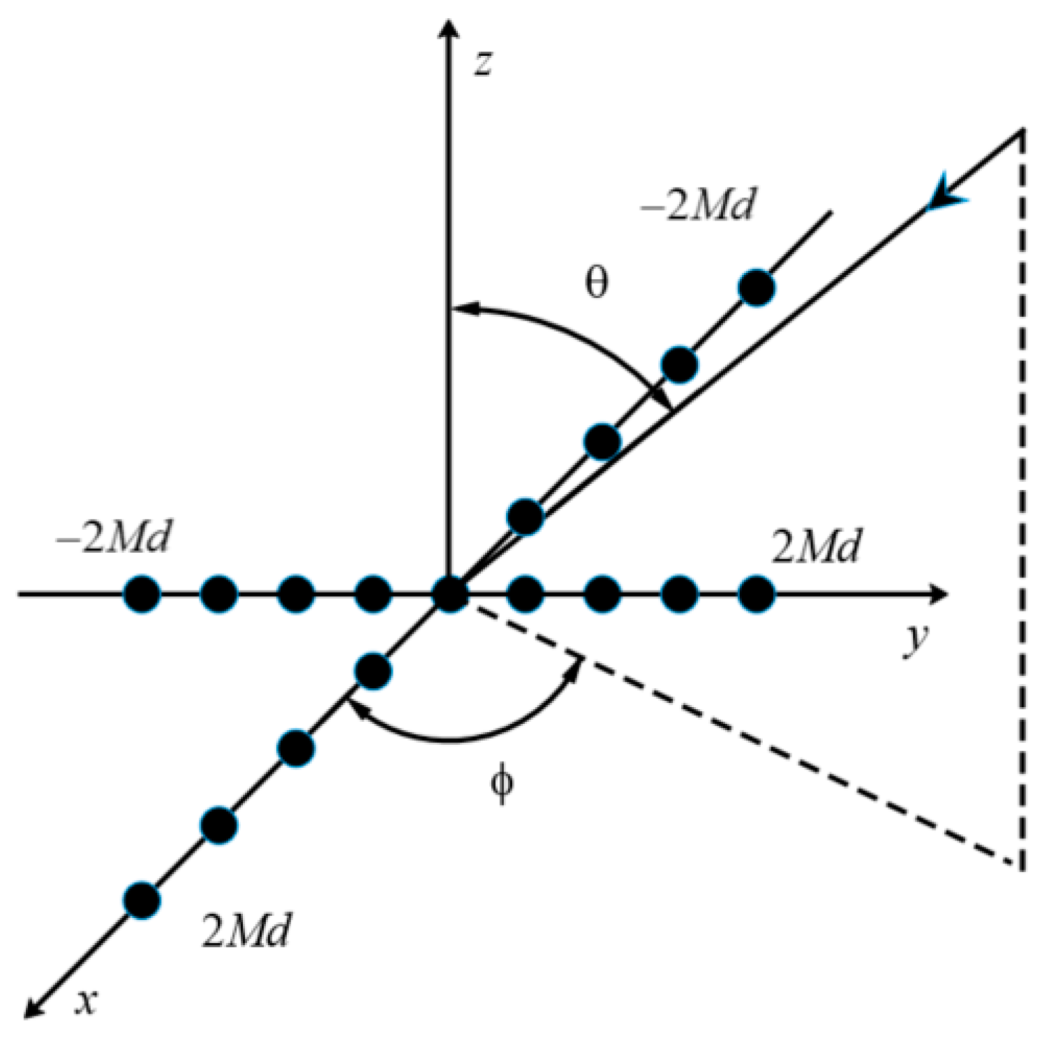
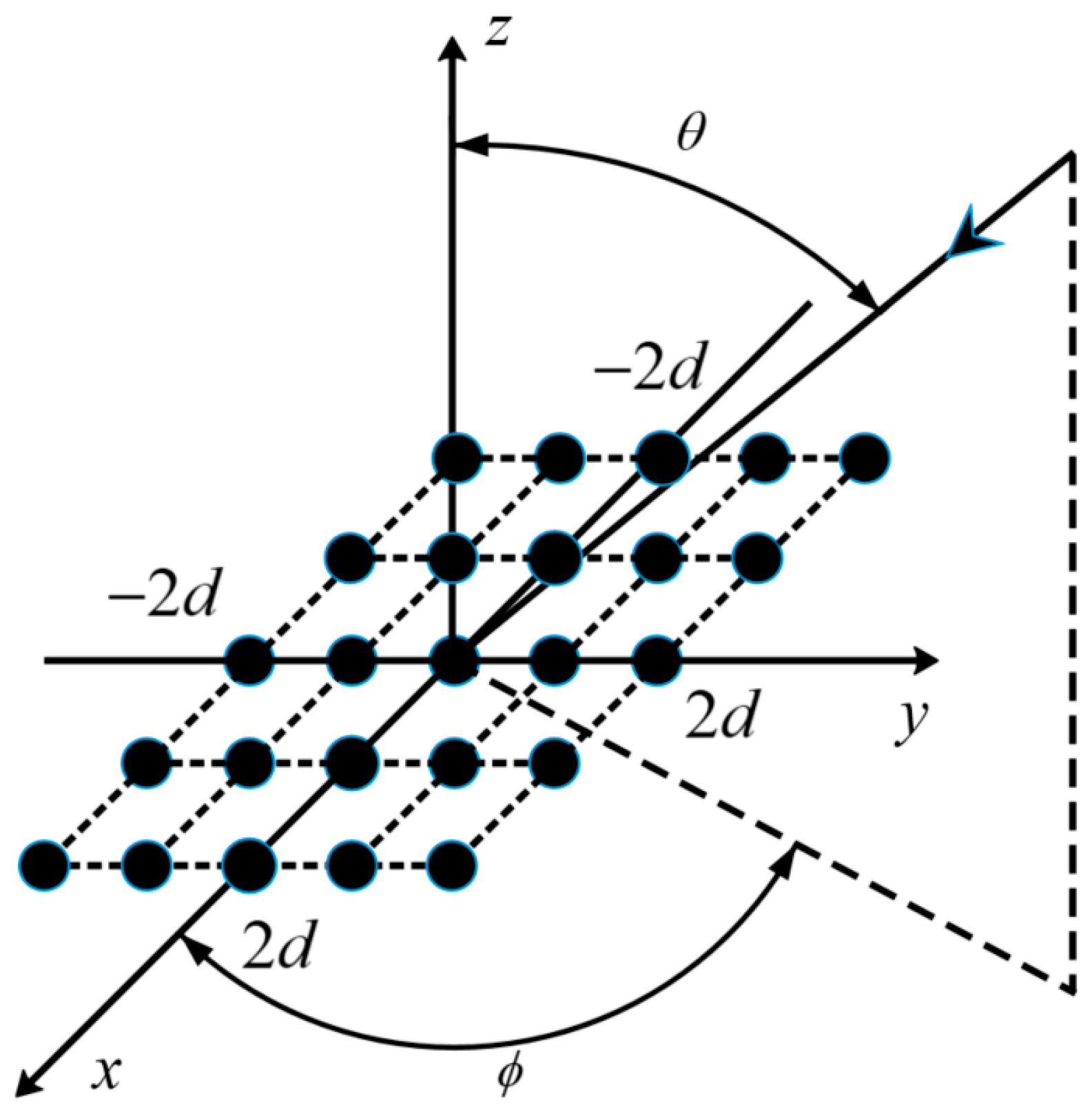
Compared with the rectangular planar array, Mills cross multiplicative array has distinct advantage in reducing elements of acoustic imaging array, without losing imaging resolution. It is an available choice to be used in UAI application.
(2)
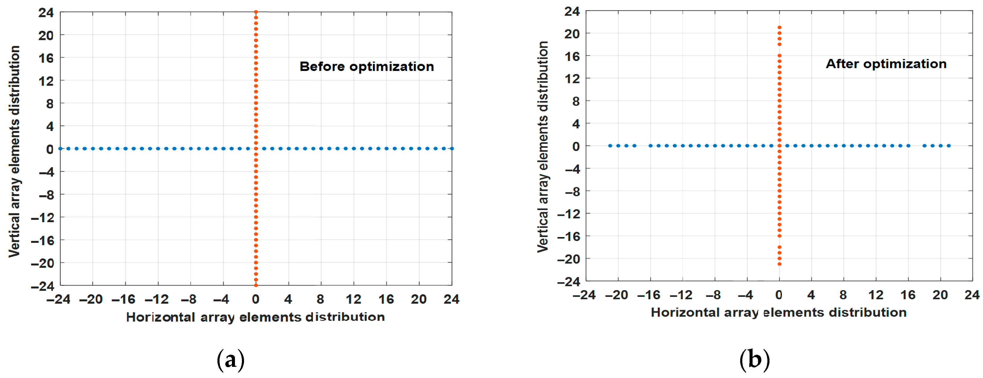
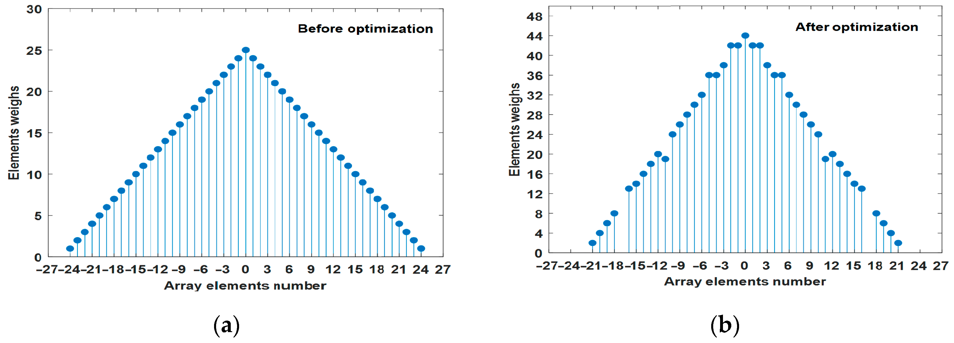
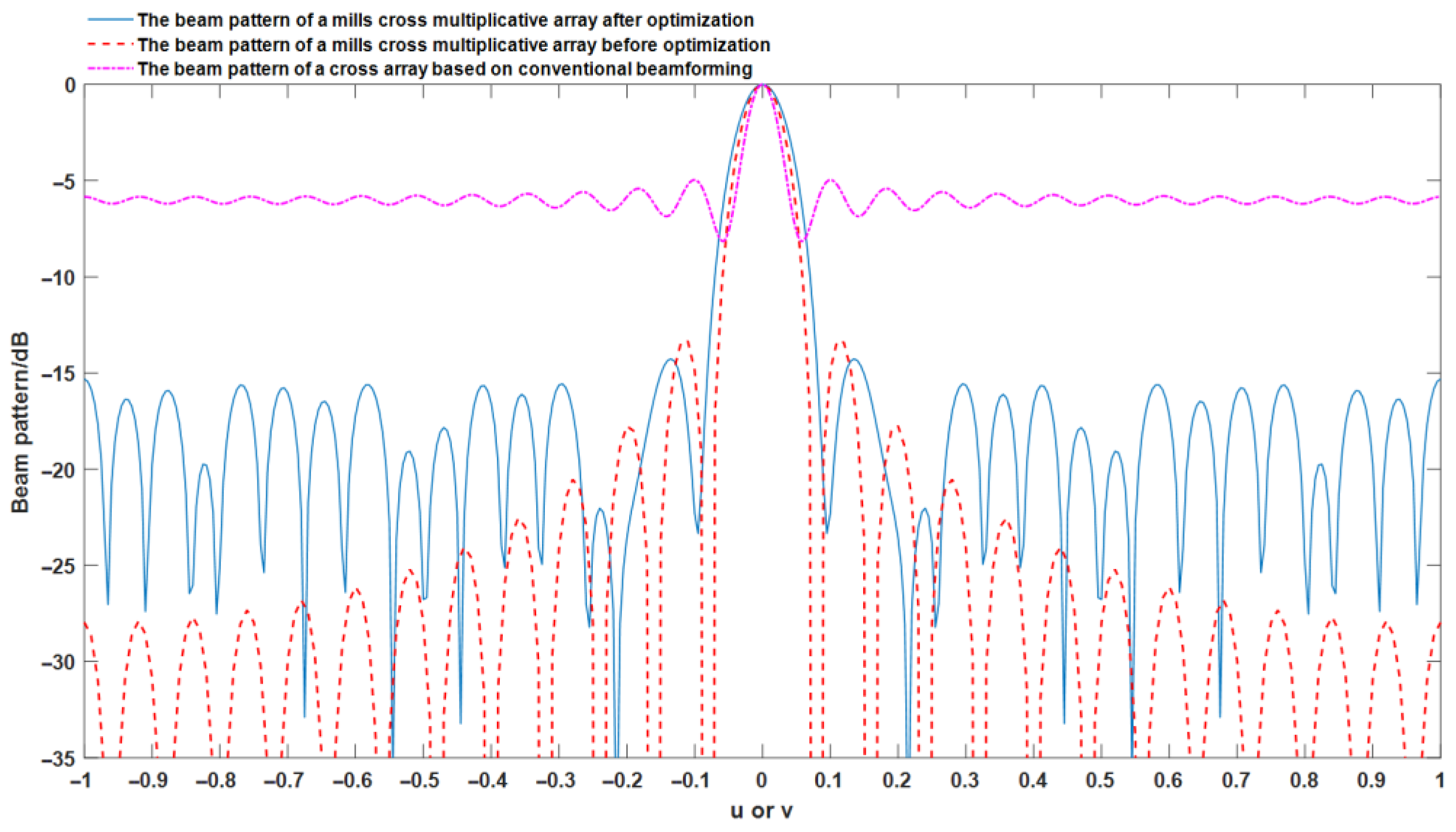
Sparse optimization of Mills cross multiplicative array can be implemented through improved genetic algorithm. The sparse cross array decreases the number of elements by 8.25% compared with MCMA, while it still keeps its advantages of beamwidth and maximum sidelobe level.
(3)
The improved genetic algorithm is effective to obtain a sparse solution of cross array. The fitness function based on pattern indices is applicable. Two-point orthogonal crossover operator can retain elitist individuals with a high probability. The sparse solution is an evolved result of mutual restraint between array elements’ survival and their weights.

Author Contributions

Conceptualization, D.T.; methodology, D.T.; software, D.T.; validation, D.T.; formal analysis, Y.L. (Yatian Li); investigation, H.Y.; resources, D.T.; data curation, Y.L. (Yatian Li); writing—original draft preparation, D.T.; writing—review and editing, Z.W.; visualization, D.T.; supervision, D.T.; project administration, H.Y.; funding acquisition, Y.L. (Yaan Li). All authors have read and agreed to the published version of the manuscript.

Funding

This research was funded by the Key Research of Special Funds for Oceanic Economy Development of Guangdong, Grant No. Guangdong Natural Resources [2021] 31, and the National Natural Science Foundation of China, Grant No. 12074318.

Institutional Review Board Statement

Not applicable.

Informed Consent Statement

Not applicable.

Data Availability Statement

Not applicable.

Acknowledgments

The authors acknowledge Zhong Luo, School of Marine Science and Technology, Northwestern Polytechnical University, for the support in data curation.

Conflicts of Interest

The authors declare no conflict of interest.

References

  1. Grelowska, G.; Kozaczka, E. Underwater acoustic imaging of the sea. Arch. Acoust. 2014, 39, 439–452. [Google Scholar] [CrossRef] [Green Version]
  2. Esmaiel, H.; Qasem, Z.A.H.; Su, H.X.; Wang, J.F.; Junejo, N.U.R. Underwater image transmission using spatial modulation unequal error protection for internet of underwater things. Sensors 2019, 19, 5271. [Google Scholar] [CrossRef] [PubMed] [Green Version]
  3. Cui, J.F.; Han, G.Y.; Su, Y.S.; Fu, X.M. Non-uniform non-orthogonal multicarrier underwater communication for compressed sonar image data transmission. IEEE Trans. Veh. Technol. 2021, 17, 10133–10145. [Google Scholar] [CrossRef]
  4. Ferreira, F.; Machado, D.; Ferri, G.; Dugelay, S.; Potter, J. Underwater optical and acoustic imaging: A time for fusion? A brief overview of the state-of-the-art. In Proceedings of the Ocean 2016 MTS/IEEE Monterey, Monterey, CA, USA, 19–23 September 2016; pp. 1–6. [Google Scholar]
  5. Trucco, A.; Palmese, M.; Fusiello, A.; Murino, V. Three-dimensional underwater acoustical imaging and processing. In Underwater Acoustic Digital Signal Processing and Communication Systems; Istepanian, R.S.H., Stojanovic, M., Eds.; Springer: Boston, MA, USA, 2002; pp. 247–274. [Google Scholar]
  6. Sutton, J.L. Real-time signal processing in underwater acoustic imaging. In Proceedings of the Real-Time Signal Processing I, SPIE Proceedings, Bellingham, WA, USA, 8 December 1978; Volume 154, pp. 38–44. [Google Scholar]
  7. Jones, I.S.F. High resolution underwater acoustic imaging. In Proceedings of the Oceans 99. MTS/IEEE Riding the Crest into the 21st Century Conference and Exhibition, Seattle, WA, USA, 13–16 September 1999; pp. 1093–1097. [Google Scholar]
  8. Konapally, P.; Tiwari, M. Review of array for underwater imaging applications. Turk. J. Physiother. Rehabil. 2021, 32, 349–356. [Google Scholar]
  9. Liu, X.; Zhao, D.; Chen, Y.; Zhou, F.; Jiang, R. A Method to Optimize Three-Dimensional Acoustic Imaging cross Array. Chinese Patent CN 108828603 A, 16 November 2018. [Google Scholar]
  10. Okino, M.; Higashi, Y. Measurement of seabed topography by multibeam sonar using CFFT. IEEE J. Ocean. Eng. 1986, 11, 474–479. [Google Scholar] [CrossRef]
  11. Alais, P.; Cesbron, N.; Challande, P.; Ollivier, F. 3-D underwater imaging system. In Acoustical Imaging; Jones, J.P., Ed.; Springer: Boston, MA, USA, 1995; pp. 723–728. [Google Scholar]
  12. Murino, V.; Trucco, A. Three-dimensional image generation processing in underwater acoustic vision. Proceeding IEEE 2000, 88, 1903–1946. [Google Scholar] [CrossRef]
  13. Yen, J.T. Beamforming of sound from two-dimensional arrays using spatial matched filters. J. Acoust. Soc. Am. 2013, 134, 3697–3704. [Google Scholar] [CrossRef] [PubMed]
  14. Holland, J.H. Adaptation in Natural and Artificial Systems; MIT Press: Cambridge, MA, USA, 1975; pp. 1–12. [Google Scholar]
  15. Kirkpatrick, S.; Gelatt, C.D.; Vecchi, M.P. Optimization by simulated annealing. Science 1983, 220, 671–680. [Google Scholar] [CrossRef] [PubMed]
  16. Kennedy, J.; Eberhart, R. Particle swarm optimization. In Proceedings of the IEEE International Conference on Neural Networks, Perth, Australia, 27 November–1 December 1995; pp. 1942–1948. [Google Scholar]
  17. Fu, Y.; Yuan, N.; Mao, J. Design of unequally spaced thinned arrays based on genetic algorithm and simulated annealing. J. Electron. Inf. Technol. 2001, 7, 700–704. [Google Scholar]
  18. Modiri, A.; Kiasaleh, K. Modification of real-number and binary PSO algorithms for accelerated convergence. IEEE Trans. Antennas Propag. 2011, 59, 214–224. [Google Scholar] [CrossRef]
  19. Li, W. Study on Sparse Optimization Design of Underwater Acoustic Imaging Sensor Array. Master’s Thesis, Nanjing University of Information Engineering, Nanjing, China, 2018; pp. 24–32. [Google Scholar]
  20. Kocak, D.M.; Caimi, F.M. The current art of underwater imaging–with a glimpse of the past and vision of the future. Mar. Technol. Soc. J. 2005, 39, 5–26. [Google Scholar] [CrossRef]
  21. Mills, B.Y.; Little, A.G. A high-resolution aerial system of a new type. Aust. J. Phys. 1953, 6, 272. [Google Scholar] [CrossRef]
  22. MacPhie, R.H. A Mills cross multiplicative array with the power pattern of a conventional planar array. In Proceedings of the 2007 IEEE Antennas and Propagation Society International Symposium, Honolulu, HI, USA, 9–15 June 2007; pp. 5961–5964. [Google Scholar]
  23. Kinsler, L.E.; Frey, A.R.; Coppens, A.B.; Sanders, J.V. Fundamentals of Acoustics, 4th ed.; John Wiley & Sons, Inc.: New York, NY, USA, 2000; pp. 188–210. [Google Scholar]
  24. Mirjalili, S.; Song, D.J.; Sadiq, A.S.; Faris, H. Genetic algorithm: Theory, Literature review and application in image reconstruction. In Nature-Inspired Optimizers; Mirjalili, S., Song, D.J., Lewis, A., Eds.; Springer: Cham, Switzerland, 2020; pp. 69–83. [Google Scholar]
  25. Mirjalili, S. Genetic Algorithm. In Evolutionary Algorithms and Neural Networks; Mirjalili, S., Ed.; Springer: Cham, Switzerland, 2019; pp. 43–53. [Google Scholar]
  26. Lipowski, A.; Lipowska, D. Roulette-wheel selection via stochastic acceptance. Phys. A Stat. Mech. Its Appl. 2012, 391, 2193–2196. [Google Scholar] [CrossRef] [Green Version]
  27. Razali, N.M.; Geraghty, J. Genetic algorithm performance with different selection strategiesin solving TSP. In Proceedings of the World Congress on Engineering 2011, London, UK, 6–8 July 2011; pp. 1134–1139. [Google Scholar]
  28. Umbarkar, A.J.; Sheth, P.D. Crossover operators in genetic algorithms: A review. ICTACT J. Soft Comput. 2015, 6, 1083–1092. [Google Scholar]
  29. Picek, S.; Golub, M.; Jakobovic, D. Evaluation of crossover operator performance in genetic algorithms with binary representation. In Bio-Inspired Computing and Applications; Huang, D.S., Gan, Y., Premaratne, P., Han, K., Eds.; Springer: Berlin/Heidelberg, Germany, 2011; pp. 223–230. [Google Scholar]
  30. Gwiazda, T.D. Genetic Algorithms Reference Volume I Crossover for Single-Objective Numerical Optimization Problems; Tomasz Gwiazda: Lomianki, Poland, 2006; pp. 344–355. [Google Scholar]
  31. Liu, Q.; Liao, Z.; Shen, Z.Y.; Wang, B.L. Genetic algorithm with multi-point orthogonal crossover operation. Comput. Eng. 2005, 31, 151–158. [Google Scholar]
  32. Soni, N.; Kumar, T. Study of various mutation operators in genetic algorithms. Int. J. Comput. Sci. Inf. Technol. 2014, 5, 4519–4521. [Google Scholar]
  33. Guan, B.X.; Zhang, C.S.; Ning, J.X. Genetic algorithm with a crossover elitist preservation mechanism for protein–ligand docking. AMB Express 2017, 7, 174. [Google Scholar] [CrossRef] [PubMed] [Green Version]
  34. Yang, X.S. Genetic algorithms. In Nature-Inspired Optimization Algorithms, 2nd ed.; Academic Press: Cambridge, MA, USA; Elsevier: Amsterdam, The Netherlands, 2020; pp. 77–87. [Google Scholar]
Figure 1. Prototype of Mills cross array used for UAI.
Jmse 10 00155 g001
Figure 2. Schematic configuration of Mills cross array with 8M + 1 elements.
Jmse 10 00155 g002
Figure 3. Schematic configuration of a rectangular planar array with ( 2 M + 1 ) × ( 2 M + 1 ) elements.
Jmse 10 00155 g003
Figure 4. Flow of improved genetic algorithm with two-point orthogonal crossover and the elitism preservation operation.
Jmse 10 00155 g004
Figure 5. Beam patterns (where M = 12). (a) RPA with (25 × 25) elements; (b) MCMA with (49 + 49) elements.
Jmse 10 00155 g005aJmse 10 00155 g005b
Figure 6. Element distribution of Mills cross multiplicative array. (a) before optimization; (b) after optimization.
Jmse 10 00155 g006
Figure 7. Element weights of Mills cross multiplicative array. (a) before optimization; (b) after optimization.
Jmse 10 00155 g007
Figure 8. The comparison of the beam patterns in u or v direction.
Jmse 10 00155 g008
Table 1. Test scheme of two-point orthogonal crossover operator.
Individual Substring Number
Individual after
IIIIII
Crossover Operation
1aaa
2aab
3aba
4abb
5baa
6bab
7bba
8bbb
Table 2. The beam performance based on three different beamforming methods.
Cross Array Beamforming MethodBeamwidthThe Maximum Sidelobe Level
cross array based on
conventional beamforming
3.15°−4.97 dB
Mills cross multiplicative array
before optimization
4.08°−13.5 dB
sparse cross array after optimization4.76°−14.27 dB
Publisher’s Note: MDPI stays neutral with regard to jurisdictional claims in published maps and institutional affiliations.

